1
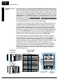
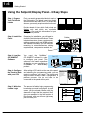
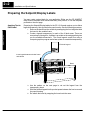
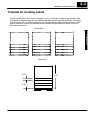
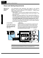
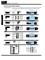
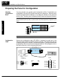
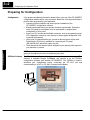
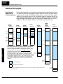
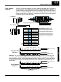
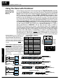
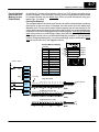
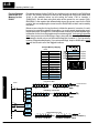
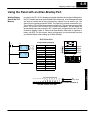
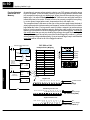
Installation and Specifications
2--11
Preparing the Panel for Communications
Assigning an
Address
How to Set the
Address
You can assign any address between 0 and 30 for valid communications to the
OP--9001 or CPU. The address is set with the DIP switch block located on the
back of the units.
The address block contains six slide switches, switch 1 through 5 are used for
addressing your Operator panel. The figure below shows the binary-weighted value
of each switch. If you are using a single panel configuration, all addresses 0--30 are
valid for communicating to the CPU. Remove power from the panel and change
switches 1 through 5 to set the desired panel address.
In this figure we have selected address No.14, placed switches 2, 3 and 4 to the right
(ON), and switches 1 and 5 to the left (OFF).
Example Address
Block Setting
ON
SW1 Position 1 2 3 4 5 6
123456
Address Value
1 2 4 8 16 T
(2 + 4+ 8 = 14)
Termination
Resistor
TIP: You must cycle power to the OP-panel to activate the new switch settings.
OP--9001 Multi-Panel Configurations
If you are connecting more than one OptiMate panel to a single CPU this is referred
to as Multi-panel configuration. Multi-panel configurations require the OP--9001
Communications Master. The OP--9001 communicates with the CPU as well as the
connected OP--panels. The OP--9001 Communications Master looks for an address
within the range of 0 to 30 for each panel connected. Each panel connected in an
RS-422 link must have a unique address. A more detailed description of multiple
panel configurations and installation is given in the OP--9001--M User Manual.
The Termination
Resistor
The last panel must be terminated when using an RS-422 communications link by
setting switch 6 (ON). Operator panels communicating more than 50 feet distance
must use RS-422 links. Systems which are using the OP--9001, in a multi-panel
application use RS-422 wiring and properly set the terminating switch. Switch 6 is
used for terminating an RS-422 communications link.
NOTE: Only the last panel of each RS-422 link should be terminated (switch 6 ON). All other
panels must have switch 6 in the OFF position. After changing the DIP switch settings,
remember to cycle power on the panel to activate the new switch settings.
Installation and
Specifications
NOTE: Set the panel address between 0--30 for valid communications mode.