1
Getting Started
1--4
Getting Started
How the OP-1312
Works
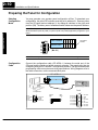
You’ll notice the OP-1312 has three LED windows with four labels beneath each of
them. There are a total of twelve labels. Each of the labels refer to user-defined field
points. These field points are actually memory locations inside your PLC where data
is stored. During configuration with the OPEditor software, you define and link these
field points to your panel. You can make a field point a read only location--in which
case, we refer to it as display data. Or you can designate a field point to store
setpoint data--in which case, the field point is a read/write location. The three LED
windows allow you to either read the display data or read and write the setpoint data.
Each label has an LED beside it. When an LED is lit, it means you have connected
the corresponding field point (in the PLC) to the panel window immediately above
the corresponding label. Let’s look at an illustrated example.
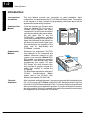
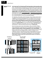
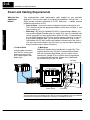
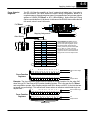
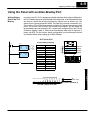
The illustration at the bottom--right of the page, shows a display window with its
four labels. Notice that beneath each bank of four labels are arrow keys and a
<SELECT>key. Pressing any<SELECT> key successively moves you up and
down the labels immediately above the key; and as their corresponding LED
becomes lit, the window displays the data from the field point memory location
that is linked to the label. If you move to a label whose field point has been setup
by you to hold setpoint data, then you can use the UP or DOWN ARROWS to
change the value shown in the window. The UP or DOWN ARROWS have no
effect,however on field points that have been setup for display data.
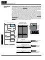
Now look at the memory map in the illustration. We have used the OPEditor
during configuration to map each of the 12 field points and a forcing function to
consecutive memory areas inside the respective PLC. For the PLCDirect
product, it started at V2000. For the Allen-Bradley product it started at N7:0. The
memory map shown is merely an example. Your base address in the PLC for the
mapping can start at any available memory location, as long as you use
consecutive locations. The download precedure (explained later) will consume
224 consecutive bits of memory--devoted entirely to the OP-1312 operations.
Below we show this as 14 consecutive 16-bit registers. If you are using the
DL305 family, it would consume 28 consecutive 8-bit registers. We’ll give you
specific examples later.
CPU Memory
PLCDirect
OP--1312 to CPU
Memory Map
N7:0
--OR-Allen-Bradley
Display Locations
Allen-Bradley PLCDirect
V2000
Location 1 data
N7:1
V2001
Location 2 data
N7:2
V2002
Location 3 data
N7:3
N7:4
V2003
V2004
Location 5 data
N7:5
V2005
Location 6 data
N7:6
V2006
Location 7 data
Location 4 data
N7:7
V2007
Location 8 data
N7:8
V2010
Location 9 data
N7:9
V2011
Location 10 data
N7:10
V2012
Location 11 data
N7:11
V2013
Location 12 data
N7:12
V2014
Force data info
N7:13
V2015
Data to be forced
Target Production
Current Production
Press Temperature
Air Pressure
Press to select location
to change or view
Press arrow
keys to change
setpoints