1
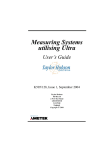
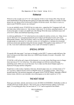
07-02
Scan Rotation Calibration
Part 2. X Axis Calibration
2-1.
By focusing on a spot with a 1 µm field of view for a few seconds, make two reference
marks on the silicon grid 100 µm apart as follows:
a. Start a fast scan using the smallest screen image size.
b. Select a 1 µm field of view (FOV) in the thick boundary area of the silicon grid, as
shown in Figure 4. The spot or mark must be visible once you zoom back out to a
larger FOV.
Silicon Grid
Place Reference
Marks Here
Figure 4. Image Area: Large Intersection of Silicon Grid.
c. Select 100 µm FOV. Using the Stage popup or the joystick, make a relative stage move
of +100 µm in x. Be careful not to move the joystick in the y direction.
d. Zoom in to 1 µm FOV for a few seconds to make the second mark.
e. Zoom out to view the reference marks. Focus the image.
f. Stop imaging in Fast Scan mode.
2-2.
Use the Point Crosshairs to align the x and y axis:
a. Turn on the Point Crosshairs feature by selecting Misc options Point Crosshairs from
the menu bar at the top of the application program screen.
b. To display the cross hairs, click the left mouse button on the “+” sign in the array of XY Stage Motion Control (“stage arrows”).
DO NOT click any mouse buttons while the cross hairs are displayed. Doing so causes
the stage to move.
c. Place the cross hairs on the first reference mark, as shown in Figure 5.
2-3.
Select Fast Scan Start. While imaging, adjust R116 (in the example shown in Fig. 5, turn
counterclockwise) until the second reference mark lines up with the horizontal cross hair.
Figure 6 shows the two reference marks on the x axis.
2-4.
Use the Measure Tool in the FIB application program to verify that the x axis offset angle
of the two reference marks is as close to zero as possible.
Page 4 of 6
Revision B, 3/97