1
Micrion 8000 Series
Focused Ion Beam System
Service Procedures Manual
Including Procedures for the Micrion 9800 FlipChip and the
MicroMill HT Systems.
Part No. 800-000049
Revision B, 3/97
Revision B, 3/97
Page 1 of 2
Notice
This document is protected by copyright. Micrion Corporation hereby conveys to purchasers of the FIB equipment described herein the right to reproduce all or any part of
this document for their own internal use. Otherwise, no part may be reproduced in any
form without the written consent of Micrion Corporation. Micrion Corporation reserves the
right to make changes to the materials contained in this document and shall not be
responsible for any damages caused by reliance upon the materials presented herein.
The following trademarks are mentioned in this document:
Univision is a trademark of Univision Technologies, Inc.
Braycote is a registered trademark of Castrol Specialty Products
Kimwipe is a registered trademark of Kimberly-Clark
VCR is a registered trademark of Cajun Technologies
SNOOP is a registered trademark of NUPRO Co.
“Micrion 8000 Series Focused Ion Beam System Service Procedures Manual”
copyright © 1997
Micrion Corporation
One Corporation Way
Peabody MA 01960-7990
All rights reserved
Printed in U.S.A.
Part number 800-000049
Revision history:
8/96, Rev. A; 3/97, Rev. B
Page 2 of 2
Revision B, 3/97
CONTENTS
PREVENTIVE MAINTENANCE
POWER UP/DOWN
01-01 POWER UP
01-02 POWER DOWN, VENT, AND RESET
CHEMICAL SAFETY
02-01 SECURING CHEMICAL SOURCES IN THE SAFE MODE
STAGE
03-01A CHECKING THE STAGE TRAVEL LIMIT SWITCHES
03-01B ADJUSTING THE STAGE LIMIT SWITCHES
03-02 STAGE LEAD SCREW INSPECTION & LUBRICATION
03-04 MIC_STAGE PROGRAM FOR STAGE ACCURACY
03-05 LASER ALIGNMENT
03-06 STAGE HEIGHT AND CARRIER FLATNESS MEASUREMENT
03-07 CLAMP ACTUATOR INSPECTION
VACUUM SYSTEM
04-01 VACUUM SYSTEM CHECKS
04-02 PROCESS MODULE VACUUM LEAK CHECK
04-03 PUMP DOWN: AUTOMATIC AND MANUAL
04-04 ROUGHING/FORE PUMP INSPECTION AND OIL CHANGE
04-05 TURBO PUMP REPLACEMENT
04-06 FORELINE TRAP ELEMENT REPLACEMENT
04-07A EPROM UPGRADE AND THERMOCOUPLE CALIBRATION
04-07B THERMOCOUPLE CALIBRATION
COLUMN
05-01 COLUMN PARAMETER LOG
05-02-05 CLEANING THE LOWER COLUMN (LENS 2) ELEMENTS: 5 NM COLUMN
05-02-10 CLEANING THE LOWER COLUMN (LENS 2) ELEMENTS: 10 NM COLUMN
05-02-25 CLEANING THE LOWER COLUMN (LENS 2) ELEMENTS: 25 NM COLUMN
05-03-05 MCP REMOVAL AND REPLACEMENT: 5 NM COLUMN
05-03-10 MCP REMOVAL AND REPLACEMENT: 10 NM COLUMN
05-03-25 MCP REMOVAL AND REPLACEMENT: 25 NM COLUMN
05-04-05 FLOOD GUN REMOVAL AND REPLACEMENT: 5 NM COLUMN
05-04-10 FLOOD GUN REMOVAL AND REPLACEMENT: 10 NM COLUMN
05-04-25 FLOOD GUN REMOVAL AND REPLACEMENT: 25 NM COLUMN
05-05 APERTURE MECHANISM LIMIT SWITCH INSPECTION
05-06 EXTERNAL APERTURE INSPECTION/LUBRICATION
05-07 APERTURE REMOVAL AND REPLACEMENT
05-09-05 COLUMN REMOVAL AND REPLACEMENT: 5 NM COLUMN
05-09-10 COLUMN REMOVAL AND REPLACEMENT: 10 NM COLUMN
05-09-25 COLUMN REMOVAL AND REPLACEMENT: 25 NM COLUMN
05-10 ION SOURCE CHANGE
05-11 GALLIUM SOURCE HEATING
05-12-05 COLUMN AND LENS CURING: 5 NM COLUMN
05-12-10 COLUMN AND LENS CURING: 10 NM COLUMN
Revision B, 3/97
Page iii of vi
05-12-25 COLUMN AND LENS CURING: 25 NM COLUMN
05-13 COLUMN ALIGNMENT
05-14 DRIFT TEST
05-15-05 APERTURE SHIELD REMOVAL, INSPECTION, & REPLACEMENT: 5 NM COLUMN
05-15-10 APERTURE SHIELD REMOVAL, INSPECTION, & REPLACEMENT: 10 NM COLUMN
05-15-25 APERTURE SHIELD REMOVAL, INSPECTION, & REPLACEMENT: 25 NM COLUMN
05-16-05 BLANKING APERTURE REPLACEMENT: 5 NM COLUMN
05-16-10 BLANKING APERTURE REPLACEMENT: 10 NM COLUMN
05-16-25 BLANKING APERTURE REPLACEMENT: 25 NM COLUMN
LOADLOCK, WORKCHAMBER
06-01 SAMPLE HOLDER INSPECTION AND CLEANING
06-02 LOADLOCK INSPECTION AND CLEANING
06-03 WORKCHAMBER INSPECTION AND CLEANING
06-04 TRANSPORT CARRIAGE INSPECTION AND ALIGNMENT
06-05 PROCESS MODULE EXTERNAL CLEANING
DEFLECTION SYSTEM
07-02 SCAN ROTATION CALIBRATION
07-03 SCAN GAIN CALIBRATION
07-04 PAN GAIN CALIBRATION
07-05 PAN ROTATION/ORTHO CALIBRATION
07-06 CHECK THE CENTER OF ROTATION
07-07 MUX SHIFT CALIBRATION
07-08 REFERENCE CURVE CALIBRATION AND DATABASE UPDATE
FLUIDS REGULATION
08-01 FLUIDS REGULATOR PRESSURE CHECK
08-02 VIBRATION ISOLATOR BALANCE ADJUSTMENT
COMPUTER, SOFTWARE
09-01 ARCHIVING/RESTORING FILES USING ARCTOOL
09-02 SETTING TIME AND DATE ON IBM RS6000 COMPUTERS
09-03 USING THE VACSERVER PROGRAM
09-04 USING THE MICRION CONSTANTS EDITOR
09-05 UPGRADING TO RS6000 COMPUTER
09-06 CONFIGURING AIX FOR A NETWORK PRINTER
DEPOSITION SYSTEM
10-01 LUBRICATING THE DUAL NOZZLE LEAD SCREWS
10-02 DUAL NOZZLE REPLACEMENT & COARSE ALIGNMENT
10-03 DUAL NOZZLE FINE ALIGNMENT
10-04 FUNNEL REPLACEMENT
10-05 FUNNEL ALIGNMENT
10-06 VERIFYING DEPO LIMIT SWITCH SETTINGS
10-07 MAKING HEATER AND COOLER BOARD SETTINGS
GAS CYLINDER REPLACEMENT
11-01 CHLORINE CYLINDER REPLACEMENT
11-02 XENON DIFLUORIDE CYLINDER REPLACEMENT
11-03 BROMINE (BR2) CYLINDER REPLACEMENT
11-04 CARBON CYLINDER REPLACEMENT
Page iv of vi
Revision B, 3/97
SYSTEM CONTROLLER
12-01 SYSCON OVERVIEW
12-02 SYSCON POWER SUPPLIES, CIRCUIT BREAKERS, & SWITCHES
12-03 ADDING AN EXTENDER BOARD
12-04 BIT3 MICROCHANNEL MULTIBUS ADAPTER: 125B
12-05A KNOB PANEL INTERFACE BOARD: 841
12-05B KNOB PANEL INTERFACE: 1810
12-06 STAGE/APERTURE MOTOR DRIVES: 893
12-07 ANALOG DRIVE BOARD: 1081
12-09 RASTER GENERATOR BOARD: 1110
12-10 SIGNAL ACQUISITION BOARD: 1381
12-11 FLOOD GUN INTERFACE: 1090
12-12 FLOOD GUN SUPPLY: 1130
Revision B, 3/97
Page v of vi
Page vi of vi
Revision B, 3/97
Preventive Maintenance Schedule
Daily/Weekly
Column Parameter Log (Service Procedure 05-01)
Fluids Regulator Pressure Check (S.P. 08-01)
Loadlock Inspection and Cleaning (S.P. 06-02)
Vacuum System Check (S.P. 04-01)
BiWeekly
Mux Shift Calibration (07-07)
Monthly
Archive/Restore Data Files—i486 and RS6000 Systems (S.P. 09-01)
Lens 2 (L2) Curing (S.P. 05-12)
Specimen Holder Inspection and Cleaning (S.P. 06-01)
Workchamber Inspection and Cleaning (S.P. 06-03)
Bimonthly
Aperture Drive Mechanism Inspection and Lubrication (S.P. 05-06)
Deposition Assembly Lubrication (S.P. 10-01)
Rough Pump Oil Change Procedure (Check Oil level ONLY ) (S.P. 04-04)
Stage Accuracy (S.P. 03-04)
Transport Carriage Lubrication (S.P. 06-04)
Turbo Pump Oil Change Procedure (Check Oil ONLY) (S.P. 04-05)
Semiannually
Clamp Actuator Inspection (03-07)
Rough Pump Oil Change (Non-GAE systems non-Fomblin) (S.P. 04-04)
Stage Hardware Inspection and Lubrication (S.P. 03-02)
Stage Travel Limit Switch Inspection (S.P. 03-01)
Turbo Pump Removal/Oil Change Procedure (Oil Change) (S.P. 04-05)
Annually
Aperture Mechanism Limit Switch Inspection and Cleaning (S.P. 05-05)
Deposition Alignment and Adjustment (S.P. 10-03)
Foreline Trap Replacement (S.P. 04-06)
Rough Pump Oil Change Procedure (Chem Series w/Fomblin) (S.P. 04-04)
System Drift Test (S.P. 05-14)
Stage Flatness Calibration (03-06)
Every year and a half
Turbo Pump Removal (Turbos w/Ceramic Bearing) (S.P. 04-05)
Revision B, 3/97
Page vii of viii
As Needed
Aperture Replacement (S.P. 05-07)
Aperture Shield Replacement (S.P. 05-15)
Blanking Aperture Replacement (S.P. 05-16)
Cleaning Column Elements (S.P. 05-02)
Column Alignment (S.P. 05-13)
Configuring AIX for a Network Printer (S.P. 09-06)
Deflection Calibration (S.P. 07-xx)
Deposition Subassembly Removal and Replacement (S.P. 10-02)
Flood Gun Installation and Test (S.P. 05-04)
GAE Cylinder Replacement (S.P. 11-xx)
Gallium Source Heating (S.P. 05-11)
Laser Alignment (S.P. 03-05)
MCP Removal and Replacement (S.P. 05-03)
Power Up (S.P. 01-01)
Power Down, Vent, and Reset (S.P. 01-02)
Pump Down (S.P. 04-03)
Reference Curve Calibration (07-08)
Removal/Installation of the Ion Beam Column (S.P. 05-09)
Securing Chemical Sources in the Safe Mode (S.P. 02-01)
Source Change (S.P. 05-10)
SysCon Board Replacement (S.P. 12-xx)
Thermocouple Calibration (S.P. 04-07)
Upgrading to RS6000 Computer (S.P. 09-05)
Using the Micrion Constants Editor (S.P. 09-04)
Vacuum Leak Check of Process Module (S.P. 04-02)
Vibration Isolator Balance (S.P. 08-02)
Page viii of viii
Revision B, 3/97
Section 1: Power Up/Down
• 01-01 Power Up
• 01-02 Power Down, Vent, and Reset
Revision B, 3/97
Page 1 of 2
Page 2 of 2
Revision B, 3/97
Service Procedure No.:
Service Procedure Title:
Applicable Systems:
Frequency of Service:
01-01
Power Up
All
As needed
Introduction
This procedure begins with the power connections for the system and its subsystems at installation; most field maintenance work begins with Part 2 or Part 3.
Tools and Materials Required
Circuit tester
Part 1. Power Cords
1-1.
This procedure begins with the system AC power disconnected and all circuit breakers in
the Power Distribution Unit (PDU) switched off. See Figure 1.
Revision B, 3/97
Page 1 of 4
01-01
Power Up
EMO
Main
Power
Elex
Mod
Consol
Ion
Pro
Mod
Fore
Line
Rough
Pump
Turbo
Pump
ON
Emergency
OFF
Vacuum
Servo
SysCon
S2 S3
CB1 S1
Computer
High voltage
Laser Computer
Ion
Pump
Contr
Turbo
Pump
Controller
elec_cab2
Figure 1 Circuit Breakers and Power Switches, Front of Electronics Module
1-2.
Plug in the main power line as shown in Figure 2.
1-3.
Switch on all circuit breakers in the PDU.
1-4.
Use a circuit tester to test the power strips that are shown in Figure 2.
Page 2 of 4
Revision B, 3/97
Power Up
Main Power
01-01
PDU
SysCon
VacCon
Servo
Computer
Laser Computer
Turbo pump
Rough pump
Power strips
HV Power Supply
Turbo
Pump
Controller
Ion Pump
(Dedicated outlet)
Figure 2. Power Cords and Power Strips, Rear of Electronics Module
1-5.
Switch off all circuit breakers in the PDU.
1-6.
Plug the VacCon, Servo, and SysCon module power cords and the Ion Pump power cord
into the power strips.
NOTE: The ion pump has its own dedicated outlet on the left power strip, as shown in Figure 2.
Part 2. If the Emergency Stop Switch is Pushed In:
If the emergency stop switch is pushed in, proceed as follows:
2-1.
Release the emergency switch from its detented position.
2-2.
Push the green ON button next to the EMO.
Revision B, 3/97
Page 3 of 4
01-01
Power Up
Part 3. Creating a Vacuum and a Beam
Once the system is connected to a power source, use the following steps to create a beam.
3-1.
Turn on water, air, and nitrogen.
3-2.
Switch on all circuit breakers in the PDU.
3-3.
Switch on the computer.
3-4.
Wait for the bootstrap.
3-5.
Log in as micrion.
3-6.
To create a vacuum, in a vacchat window type the automatic pump-down command:
ap (see Service Procedure 04-03)
3-7.
To cure the column, follow Service Procedure 05-12. The length of the cure depends upon
the length of time the chamber was vented.
3-8.
To heat the source, follow Service Procedure 05-11.
3-9.
From the application program screen, select Powerup. Powerup performs an orderly
restart of the ion beam, including stage movement to the ion faraday and electron faraday
cups.
Page 4 of 4
Revision B, 3/97
Service Procedure No.:
Service Procedure Title:
Applicable Systems:
Frequency of Service:
01-02
Power Down, Vent, and Reset
All
As Needed
Introduction
You should power down when you want to get into some part of the hardware system, such as the
SysCon module or the chamber, or when you want to disconnect cables from the column, etc.
There are automatic as well as manual procedures for powering down, resetting, and venting.
Vent
Using the autovent command or a series of manual vent commands, you can disable the vacuum
pumps and bring the pressure in the chamber to atmosphere. Some systems are equipped with a
single fore/rough pump, and other systems have dual (fore and rough) pumps. The autovent command will automatically vent either type of system. Manual venting procedures are different for
single versus dual pump systems, and are described in Part 3.
Reset
Reset refers to the reset of the computer and the SysCon module. Reset after emergency shutdown
is also included in this procedure.
Requirements
•
•
•
vacchat window open (see Service Procedure 09-03)
FIB application running
Access to the switches shown in Figure 1
NOTICE
Per paragraph 11.1 of Safety Guidelines for Semiconductor Manufacturing
Equipment (S2-93), this procedure is a Type 3 task. Specifically:
“Equipment is energized. Live circuits are exposed and accidental contact
is possible. Potential exposures are less than 30 volts RMS, 42.2 volts
peak, 240 volt-amps, and 20 Joules.”
Revision B, 3/97
Page 1 of 12
01-02
Power Down, Vent, and Reset
Part 1. System Preparation
Configure the Chemical Sources in “Safe” Mode
Before performing the tasks described in this procedure, you must put the chemical sources in a
“safe” mode; see Service Procedure 02-01.
WARNING
Do not proceed until the chemical sources are secure.
The chemical reservoirs in FIB systems contain hazardous materials. Labels affixed to the exterior of a chemical
cabinet identify the chemical(s) contained inside. If a
chemical source is not in its “safest” state, as described in
Service Procedure 02-01, it is possible for a combination
of component failures to release the chemical(s) through
a cabinet’s delivery line, a roughing line, a purging line, or
from a chemical reservoir into the workchamber. Do not
open the workchamber, or disassemble any part of the
vacuum pumping system, or detach any gas line from any
chemical cabinet until you are sure that every chemical
source attached to the FIB system is in its “safest” state.
Part 2. Power Down
This procedure begins with the FIB application program running. The first task is to bring down
the high voltage.
2-1.
Power down the column through the application program.
WARNING
Dangerously high voltages are present in the process
module while the FIB system is powered up. Do not rely
only on the software Power Down function. Disable the
voltages using both manual and automatic procedures.
2-2.
On the SysCon module, switch OFF the Deflection, MCP, and Flood Gun power swtiches
(S1, S2, and S3).
2-3.
Select the task you are going to perform, and switch off the specified switches that are
listed in Table 1 and shown in Figure 1.
Page 2 of 12
Revision B, 3/97
Power Down, Vent, and Reset
01-02
Table 1: Subsystems and Which Circuits to Switch Off
To work on:
Switch OFF:
Ion Beam Column/
High Voltage Power
HV Power Supply(s)/Focus Power Supply
SysCon Boards
S1, S2, S3, CB1
VacCon Boards
Vacuum Control
Servo Boards, Motors
Servo Control
Workchamber
HV Power Supply(s)/Focus P/S, CB1, S1, S2, S3
Turbo Pump
HV Power Supply(s)/Focus P/S, CB1, S1, S2, S3,
Fore, Rough, and Turbo CBs
MCP module
S2
2-4.
To vent the system, go to Part 3.
When all necessary manual switches have been switched off, you can safely perform your task.
Revision B, 3/97
Page 3 of 12
01-02
Power Down, Vent, and Reset
EMO
Main
Power
Elex
Mod
Consol
Ion
Pro
Mod
Fore
Line
Rough
Pump
Turbo
Pump
ON
Emergency
OFF
Vacuum
Servo
SysCon
S2 S3
CB1 S1
Computer
High voltage
Laser Computer
Ion
Pump
Contr
Turbo
Pump
Controller
elec_cab2
Figure 1. Circuit Breakers and Power Switches, Front of Electronics Module
Page 4 of 12
Revision B, 3/97
Power Down, Vent, and Reset
01-02
Table 2 shows the order in which the system may be powered down all the way. You do not have
to power down all the way for most of your repair and maintenance procedures.
Table 2: System Shutdown
system
state
ion
column
status
Application
program
vacuum
status
X Windows
& Process
Watcher
program
AIX
computer
status
electrical
power
status
fluids
status
to go to
next lower
state:
8
powered
up
running
at vacuum
running
running
on
on
enabled
select
Powerdown
function
7
powered
down
running
at vacuum
running
running
on
on
enabled
select Quit
function
6
powered
down
not running
at vacuum
running
running
on
on
enabled
enter av
command
(vacchat)a
5
powered
down
not running
at
atmosphere
running
running
on
on
enabled
click on
Quit & Exit
(Watcher)
4
powered
down
not running
at
atmosphere
not running
running
on
on
enabled
enter
shutdown
command
(AIX)b
3
powered
down
not running
at
atmosphere
not running
not
running
on
on
enabled
switch computer off
2
powered
down
not running
at
atmosphere
not running
not
running
off
on
enabled
switch
main
breaker off
1
powered
down
not running
at
atmosphere
not running
not
running
off
off
enabled
shut off
water, air, &
nitrogen
0
powered
down
not running
at
atmosphere
not running
not
running
off
off
disabled
a. Start the vacchat program through the Process Watcher program’s window. Wait for venting to complete before proceeding.
b. You must log out and log in again as root (password required) to execute the shutdown command.
Part 3. Automatic and Manual Venting
To extend the life of the floodgun, allow 15 to 30 minutes for the flood gun to cool down before
venting the system. There are two ways to vent a system: automatically and manually. Each of
these procedures assumes that the workchamber has been pumped down and that the fore (fore
and rough pumps for systems with dual “wet” pumps) and turbo pumps are running.
3-1.
To automatically vent the system, proceed as follows:
a. Make sure that the loadlock door is shut.
b. Open a vacchat window (see Service Procedure 09-03).
c. At the vacchat prompt, type the autovent command to vent the system:
av
Revision B, 3/97
Page 5 of 12
01-02
3-2.
Power Down, Vent, and Reset
To manually vent a single (fore/rough) pump system, proceed as follows (see Figure 2
for valve locations):
a. Make sure that the loadlock door is shut.
b. Open a vacchat window (see Service Procedure 09-03).
c. At the vacchat prompt, check the status of the valves by typing:
sv
The system will display the status of the valves:
V1C V2C V3C V4C V5C V6C VIO VTIO VTPO
The valves should be in the states shown above; V1 through V6 should be closed, and
VTP and VTI should be open.
If any of the valves V1 through V6 is open, close each valve by typing the vacchat
close command. For example, V1 is closed with the following command:
clv1
d. To begin manual pump down of the loadlock, close VTP and VTI with the following
vacchat commands:
clvtp
clvti
Be sure that VTI is closed before proceeding with the loadlock pumpdown. If VTI
is not closed before loadlock pumpdown begins, the vacuum in the turbo pump line
will suck contaminants from the roughing (and possibly the exhaust) line into the
turbo pump and the workchamber.
e. Open V1 and V3 with the following vacchat commands:
opv1
opv3
Wait approximately 5 seconds, then open V4 by typing:
opv4
Opening V3 begins the evacuation of the loadlock through a small diameter vacuum
line, and at a relatively low flow rate; this reduces the amount of particulate contamination generated by the evacuation of the loadlock. Opening V4 continues the evacuation of the loadlock through a large diameter vacuum line.
f. Close V3 with the following vacchat command:
clv3
g. Check the status of TC2 by typing:
stt2
Page 6 of 12
Revision B, 3/97
Power Down, Vent, and Reset
01-02
h. When TC2 < 0.065 torr, close V1 by typing:
clv1
i. At the vacchat prompt, type the following command:
opv2
j. Shut off the ion pump, the HCIG, the turbo pump, and the fore pump with the following commands:
ipn
hcpd
hpn
fpn
k. Wait a minimum of two minutes for the turbo pump to stop spinning.
l. Open the vent valve with the following command:
opv5
m. It will take up to 20 minutes for the workchamber and loadlock to reach atmospheric
pressure. Check pressure in the loadlock and workchamber by typing the following
vacchat command:
stlp
The system will respond with either:
The loadlock is under vacuum
or
The loadlock is at atmosphere
Because V2 and V4 are open, the workchamber and the loadlock are at the same pressure.
n. When the system reports that the loadlock (and workchamber) is at atmosphere, type
the following commands:
clv2
clv4
clv5
Revision B, 3/97
Page 7 of 12
01-02
Power Down, Vent, and Reset
8000, 9800, MicroMill HT
Vacuum System
Schematic
(Single Pump)
GAE
Cabinet (see note 4)
Ion Pump
(IP)
VI
TC2
V6
Carbon
Cabinet
Workchamber
Loadlock
V4
V3
V2
Ionization
Gauge
(HCIG/CCIG)
CA (see note 3)
TC3
N2
Leak-Check
Valve
Vent Valve
(see note 1)
Turbo
Pump
(HP)
V5
TC4
To Exhaust
V
VTI
TC1
(see
note 2)
Trap
Foreline/Roughing
Pump (FP)
V1
Leak-Check Valve
Notes:
1) Several seconds after the turbo pump is powered down, the vent valve opens automatically to vent the pump with nitrogen.
2) VTI (turbo-isolation valve), normally kept open, is closed to isolate the pump during loadlock cycles.
3) CA clamps the specimen holder to the stage.
4) The MicroMill HT is not equipped with the GAE and Carbon cabinets.
Figure 2. Single Pump Vacuum System
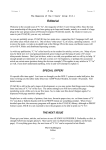
3-3.
To manually vent a dual (fore and rough) pump system, proceed as follows (see Figure
3 for valve locations):
a. Make sure that the loadlock door is shut.
b. Open a vacchat window (see Service Procedure 09-03).
c. At the vacchat prompt, check the status of the valves by typing:
sv
The system will display the status of the valves:
V1C V2C V3C V4C V5C V6C VIO
Page 8 of 12
Revision B, 3/97
Power Down, Vent, and Reset
01-02
The valves should be in the states shown above; V1 through V6 should be closed, and
VI should be open.
If any of the valves V1 through V6 is open, close each valve by typing the vacchat
close command. For example, V1 is closed with the following command:
clv1
d. Turn on the rough pump by typing:
rpy
e. Open V1 and V3 with the following vacchat commands:
opv1
opv3
Wait approximately 5 seconds, then open V4 by typing:
opv4
Opening V3 begins the evacuation of the loadlock through a small diameter vacuum
line, and at a relatively low flow rate; this reduces the amount of particulate contamination generated by the evacuation of the loadlock. Opening V4 continues the evacuation of the loadlock through a large diameter vacuum line.
f. Close V3 with the following vacchat command:
clv3
g. Check the status of TC2 by typing:
stt2
h. When TC2 < 0.065 torr, close V1 by typing:
clv1
i. Turn off the rough pump with the following vacchat command:
rpn
j. At the vacchat prompt, type the following command:
opv2
k. Shut off the ion pump, the HCIG, the turbo pump, and the fore pump with the following commands:
ipn
hcpd
hpn
fpn
l. Wait a minimum of two minutes for the turbo pump to stop spinning.
Revision B, 3/97
Page 9 of 12
01-02
Power Down, Vent, and Reset
m. Open the vent valve with the following command:
opv5
n. It will take up to 20 minutes for the workchamber and loadlock to reach atmospheric
pressure. Check pressure in the loadlock and workchamber by typing the following
vacchat command:
stlp
The system will respond with either:
The loadlock is under vacuum
or
The loadlock is at atmosphere
Because V2 and V4 are open, the workchamber and the loadlock are at the same pressure.
o. When the system reports that the loadlock (and workchamber) is at atmosphere, type
the following commands:
clv2
clv4
clv5
Page 10 of 12
Revision B, 3/97
Power Down, Vent, and Reset
01-02
8000, 9800, MicroMill HT
Vacuum System
Schematic
(Dual Pump System)
GAE
Cabinet
Ion Pump
(IP)
VI
(see note 3)
TC2
V6
Carbon
Cabinet
Workchamber
Loadlock
V4
V3
V2
Ionization
Gauge
(HCIG/CCIG)
CA (see note 2)
TC3
To Exhaust
N2
(see note 4)
Vent Valve
(see note 1)
Turbo
Pump
(HP)
V5
LeakCheck
Valve
TC4
Foreline
Pump (FP)
V
VTI
TC1
(see note 4)
Trap
V1
Roughing
Pump (RP)
Leak-Check
Valve
Notes:
1) Several seconds after the turbo pump is powered down, the vent valve opens automatically to vent the pump with nitrogen.
2) CA clamps the specimen holder to the stage.
3) The MicroMill HT is not equipped with the GAE and Carbon cabinets.
4) Some dual pump systems are not equipped with TC4 and VTI.
Figure 3. Dual Pump Vacuum System
Revision B, 3/97
Page 11 of 12
01-02
Power Down, Vent, and Reset
Part 4. Shutdown
4-1.
Quit the FIB application and click the Quit & Exit button on the Process Watcher.
4-1.
At the shell prompt (not in an xterm window), log out of the system.
4-2.
Log in as root and enter the password.
4-3.
As the root user, enter the command:
shutdown now
This command shuts down the operating system in an orderly and safe manner.
NOTICE: DO NOT PRESS THE RESET BUTTON
If an application hangs (no mouse response), DO NOT use the computer
Reset button to reboot. Use of the Reset button crashes the operating
system. To clear the hang, press the three keys: CTRL-ALT-BACKSPACE;
this will terminate X Windows without crashing the operating system. Then
type xinit at the shell prompt to start the user interface (X Windows).
Part 5. Resetting After an Emergency Shutdown
An emergency shutdown is one in which someone pressed the red EMO button. To recover, proceed as follows:
5-1.
Switch the computer off.
5-1.
Release the Emergency button (above the SysCon section) from its detented position.
5-2.
Press the green ON button next to the Emergency button.
5-3.
Switch the computer on.
5-4.
Log back in to the computer (the application restarts automatically; see Service Procedure
01-01).
Page 12 of 12
Revision B, 3/97
Section 2: Chemical Safety
•
•
•
•
•
•
•
•
•
•
•
02-01 Securing Chemical Sources in Safe Mode
MSDS Apiezon A Oil
MSDS Perfluorinated pPolyethers (Fomblin)
MSDS Gallium Ingot
MSDS Oxygen
MSDS Platinum (II) hexafluoroacetylacetonate
MSDS Styrene
MSDS TEOS (Tetraethoxysiloxane)
MSDS TMCTS (Tetramethylcyclotetrasiloxane)
MSDS Tungsten carbonyl
MSDS Xenon difluoride
Revision B, 3/97
Page 1 of 2
Page 2 of 2
Revision B, 3/97
Service Procedure No.:
Service Procedure Title:
Applicable Systems:
Frequency of Service:
02-01
Securing Chemical Sources in the Safe Mode
All
As needed
Introduction
This procedure describes the process of securing the chemicals in the system so that maintenance
and repair procedures can be carried out safely.
To reduce the risk of accidental exposure to toxic chemicals while working on the FIB system,
place the chemical subsystems in the “safe” mode as specified in this section.
Before venting and opening the FIB process module, let the system run under high vacuum for
12-24 hours after using any chemical.
Materials Required
This procedure requires the use of the following materials:
• Standard field service tools
• Nitrile rubber gloves
• Cylinder shutoff tool
WARNING
The chemical cabinets attached to FIB systems normally
contain hazardous materials. Labels affixed to the exterior
of a chemical cabinet identify the chemical(s) contained
inside. If a chemical cabinet is not in its “safest” state, as
defined below, it is possible for a combination of component failures to release the chemical(s) through the cabinet’s delivery line, its roughing line, or its purging line. Do
not open the workchamber, disassemble any part of the
vacuum pumping system, or detach any gas line from any
chemical cabinet until you are sure that every chemical
cabinet attached to the FIB system is in its “safest” state.
Revision B, 3/97
Page 1 of 6
02-01
Securing Chemical Sources
Part 1. Secure the GAE Cabinet
Configure the GAE cabinet in the “safe” mode as follows.
1-1.
Make sure that the GAE cabinet exhaust system is operating correctly. Note the position of
the exhaust gate valve (so that you can restore it later). Open the exhaust gate valve fully
before opening the GAE cabinet door.[1]
1-2.
Open the GAE cabinet door and by-pass the safety interlock shut-off switch as follows:
By-pass the switch with the cabinet door open by pulling the switch actuator toward you
until it clicks into the extended by-pass position.
(Opening the cabinet door has the same effect as shutting off the Pneu Valve Shutdown
switch. It shuts off the dc power controlling the pneumatic valves. By-passing the switch
restores dc power to the pneumatic valves.)
1-3.
With dc power for controlling the pneumatic valves enabled, make sure that the push-button switch labeled Pneu Valve Shutdown on the GAE cabinet is illuminated (green).
1-4.
Close the manual valve on the Xenon Difluouride (XeF2) cylinder assembly by turning it
1/4 turn clockwise.
1-5.
Use the Gas Control popup (in the Misc menu), to make sure that valves V12 through
V17, and V20 are closed. To close valve V17, click on the valve icon to obtain the setpoint
dialog box, then click on the LeakValve toggle button so that it reads OFF.
WARNING
Do not touch the connectors exposed on the bank of solenoid-operated valves in the upper left-hand corner of the
GAE cabinet. When the Pneu Valve Shutdown switch is
on, there is a 24 volt, 5 ampere, dc potential present on
the connectors. A short-circuit caused by introducing a
conductive metal object such as a tool or a finger ring
could generate enough heat energy to cause burns
before the power supply automatically switches off.
1-6.
Pump out the chemical delivery lines in the GAE cabinet up to V12:
a. Start the roughing pump by clicking on the RP (FP for single pump systems) icon in
the Gas Control Popup.
b. When TC1 reads ≤0.01 torr, open V13, V15, and V16.
c. When BT1 reads base pressure (≅ 0.00 T), record the reading.
d. Close V13, V15, and V16.
[1] If the duct has a high/low flow sensor, increasing the air flow may cause an alarm condition, triggering the
GAE interlock circuit. If necessary, bypass (jumper) the flow sensor. The interlock resets after clearing the
alarm by a push-button on the rear of the vaccon unit or a remote customer provided push-button.
Page 2 of 6
Revision B, 3/97
Securing Chemical Sources
02-01
e. Manually close the Process Gas Shutoff valve on the outside of the GAE cabinet.
f. Turn off the roughing pump.
g. To switch off power to the solenoid valves, press the push-button switch labeled Pneu
Valve Shutdown on the GAE cabinet so that the green light is off. Before continuing,
be certain that the valves listed in the table below are in the specified state.
Table 1:
Valve
State
V12
Closed
V13
Closed
V14
Closed
V15
Closed
V16
Closed
V17
Closed (Off)
V20
Closed
Part 2. Secure the Carbon Cabinet
Configure the Carbon cabinet in the “safe” mode as follows.
2-1.
Open the Carbon cabinet door and bypass the safety interlock shut-off switch on the door
opening of the Carbon cabinet.
Bypass the switch with the cabinet door open by pulling the switch actuator toward you
until it clicks into the extended by-pass position.
(Opening the cabinet door has the same effect as shutting off the Pneu Valve Shutdown
switch: the dc power controlling the pneumatic valves is shut off. Bypassing the switch
restores dc power to the pneumatic valves.)
2-2.
Close the manual valve on the Carbon cylinder assembly by turning it 1/4 turn clockwise.
2-3.
Gain access to the Carbon Gas Control Popup dialogue box.
2-4.
Close valves V31 through V36. To close valve V35, click on the valve icon to obtain the
setpoint dialog box, then click on the LeakValve toggle button so that it reads OFF.
2-5.
Click on the RP (FP for single pump systems) icon to turn on the roughing pump. Wait
until TC1 reads ≤0.01 torr, then open valves V31, V32, and V33.
2-6.
Wait for BT1 to read base pressure (≅ 0.00 T).
2-7.
Close valves V31, V32, and V33, then turn off the roughing pump.
Revision B, 3/97
Page 3 of 6
02-01
2-8.
Securing Chemical Sources
To switch off power to the solenoid valves, press the push-button switch labeled Pneu
Valve Shutdown on the Carbon cabinet so that the green light is off. Before continuing, be
certain that the valves listed in the table below are in the specified state.
Table 2:
Valve
State
V31
Closed
V32
Closed
V33
Closed
V34
Closed
V35
Closed (Off)
V36
Closed
Part 3. Secure the Siloxane Cabinet
Configure the SiO2 cabinet in the “safe” mode as follows.
3-1.
Access the Siloxane popup from the Misc menu, and proceed.
3-2.
Close the manual 1/4-turn valve on the SiO2 bottle assembly.
3-3.
Using the Gas Control popup, close valves V41 through V46.
3-4.
Turn on the rough pump; Wait until TC1 reads ≤0.01 torr, then open V43.
3-5.
Wait for BT1 to read base pressure (≅ 0.00 T).
3-6.
Close V53; turn off the rough pump.
3-7.
To switch off power to the solenoid valves, press the push-button switch labeled Pneu
Valve Shutdown on the SiO2 cabinet so that the green light is off. Before continuing, be
certain that the valves listed in the table below are in the specified state.
Table 3:
Page 4 of 6
Valve
State
V41
Closed
V42
Closed
V43
Closed
V44
Closed
V45
Closed (Off)
V46
Closed
V19
Closed
Revision B, 3/97
Securing Chemical Sources
02-01
Part 4. Secure the Oxygen Cabinet
Configure the O2 cabinet in the “safe” mode as follows.
4-1.
Access the Oxygen popup dialogue box and proceed.
4-2.
Close the manual 1/4 turn valve on the O2 bottle assembly.
4-3.
Close valves V51 through V56.
4-4.
Turn on the rough pump; Wait until TC1 reads ≤0.01 torr, then open V53.
4-5.
Wait for BT1 to read base pressure (≅ 0.00 T).
4-6.
Close V53; turn off the rough pump.
4-7.
To switch off power to the solenoid valves, press the push-button switch labeled Pneu
Valve Shutdown on the O2 cabinet so that the green light is off. Before continuing, be certain that the valves listed in the table below are in the specified state.
Table 4:
Revision B, 3/97
Valve
State
V51
Closed
V52
Closed
V53
Closed (Off)
V54
Closed
V55
Closed
V56
Closed
Page 5 of 6
02-01
Page 6 of 6
Securing Chemical Sources
Revision B, 3/97
Material Safety Data Sheet (MSDS) — Apiezon A Oil (Varian Turbo Pump T.A. Oil)
Emergency contact: N/A
General comments: This oil is used in Varian V-1000 turbo pumps without ceramic bearings
This MSDS is provided for general information only. For information about the manufacturer of a
particular chemical, contact the environmental health and safety coordinator at Micrion Corporation, 508-531-6464.
Manufacturer: Micanite and Insulators Co. LTD
Distributor:
Biddle Instruments
510 Township Line Road
Blue Bell, PA 19422
Telephone:
215-646-9200
Varian Part No: 969-9901,2
Substance Identification
Substance: Apiezon A OilCAS# 64742-65-0
Trade names and synonyms: Varian Turbo T.A. Oil
Physical Data
Boiling point @760 mm Hg: >350° CSpecific gravity @ 20° C: 0.865
Vapor pressure: 3 x 10⁻⁶ mm Hg @30°C Evaporation Rate: Negligible
Solubility in H2O: insolubleAppearance and Odor: pale amber liquid, no odor
Fire and Explosion Data
Flash point: 210°C (IP 34)Extinguishing agents: Use carbon dioxide, dry powder, or dry sand.
Special Fire fighting procedures: NoneUnusual fire and explosion hazards: None
Health Hazard Data
Health Hazards: None knownCarcinogenicity: Not regulated
Signs and Symptoms of Exposure: None likely
Emergency first aid procedures: In case of accidental eye contact, flush with clean water. If
ingested, do not induce vomiting, obtain medical attention.
Reactivity Data
Stable
Hazardous polymerization will not occur.
Revision B, 3/97
Page 1 of 2
Spill or Leak Procedures
Wipe up or absorb with sand, earth, or sawdust. Do not wash directly into any public water or
sewer system.
Waste Disposal Method
Dispose of according to local regulations for mineral oils.
Special Protection Information
Respiratory protection: None required.
Ventilation: Not required
Protective gloves: Not required.
Eye protection: Not required
Other protective clothing or equipment: Coverall recommended.
Washing/hygienic practices: Wash skin after contact and generally observe good standards of
hygiene.
Special Precautions
Handling & storage precautions: None
Page 2 of 2
Revision B, 3/97
Material Safety Data Sheet (MSDS) — Bromine
Emergency contact: Chemtrec 800-424-9300
This MSDS is provided for general information only. For information about the manufacturer of a
particular chemical, contact the environmental health and safety coordinator at Micrion
Corporation, 508-531-6464.
Substance Identification
Chemical name: BromineChemical family: halogen
Formula: Br2
Molecular weight: 159.81
CAS#: 7726-95-6
Physical Data
Dark red liquid
Boiling point: 59.5° CEvaporation rate: not available
Vapor pressure (mmHg): 175mm @ 20° CMelting point: —7.25° C
671mm @ 55° C
Vapor density (air = 1): 7.14Specific gravity: 3.102
Solubility in water: 3.6 gm per 100 ml @ 20° CAppearance: Dark red liquid
Health Hazard Data
Hazardous components:bromine (99 - 100%)
OSHA PEL: 8H
TWA: 0.7 mg/m3
NIOSH REL: bromine-air 10HACGIH TLV: 2.5 mg/m3
TWA: 0.1 PPMSTEL: 0.3 PPM
Routes of entry: inhalation, skin absorption, ingestion
Health hazards—acute and chronic: May be fatal if inhaled, swallowed, or absorbed through skin.
Causes burns. Material is extremely destructive to tissue of the mucous membranes and upper respiratory tract, eyes, and skin. Inhalation may be fatal as a result of spasm, inflammation and
edema of the larynx and bronchi, chemical pneumonitis and pulmonary edema.
Signs and symptoms of exposure: severe burns, coughing, wheezing, laryngitis, shortness of
breath, headache, nausea, and vomiting.
Medical conditions generally aggravated by exposure: no data available
Emergency and first aid procedures:
Revision B, 3/97
Page 1 of 2
Inhalation: remove victim to fresh air; if breathing is difficult, administer oxygen; if not breathing,
give artificial respiration; consult a physician.
Ingestion: wash out mouth with water if victim is conscious; get Immediate medial attention; discard contaminated clothing and shoes. Eye Contact: flush with water for at least 15 minutes while
removing contaminated clothing and shoes; assure adequate flushing by separating eyelids with
fingers; obtain medical attention. Skin Contact: wash with soap; flush with water for 15 minutes.
Fire and Explosion Hazard Data
Flash point: does not flashFlammable limits: not applicable
Extinguishing media: noncombustible
Special fire fighting procedures: A self-contained breathing apparatus and full protective clothing
should be worn when fighting fires. Prevent contact with skin and eyes.
Unusual fire and explosion hazards: strong oxidizing agent! Contact with other material may
cause fire. Container explosion may occur under fire conditions.
Reactivity Data
Stability: unstable
Conditions to avoid: Contact with other material.
Incompatibility (materials to avoid): reducing agents, alkali metals, finely powdered metals, aluminum, corrodes steel, stainless steel, galvanized iron, copper, copper alloys, organic materials.
Hazardous decomposition or by-products: nature of decomposition products not known.
Precautions for Safe Handling and Use
If material is released or spilled: Evacuate area. Wear self-contained breathing apparatus and full
protective equipment, such as a butyl rubber chemical proof air suit, with breathing air supplied.
Cover with dry lime, sand, or soda ash. Place in covered containers. Wash the spill site after completing material pickup.
For handling and storing: Store in a cool, dry place, away from heat and direct sunlight. Keep container closed tightly. Avoid breathing vapors. Do not breathe vapor; do not get in eyes, on skin, or
on clothing Avoid prolonged exposure. Harmful vapor; corrosive; lachrymator; highly toxic.
Other precautions: Do not store near, nor allow contact with, clothing and other combustibles.
Control Measures
Respiratory protection required: NIOSH-MSHA-approved respirator.
Ventilation: should be handled only in a fume hood or glove box.
Protective gloves: chemical resistant rubber or neoprene
Eye protection: 8 inch faceshield—minimum.
Other protective clothing or equipment: as required by your company
Work/hygienic practices: wash thoroughly after handling.
Page 2 of 2
Revision B, 3/97
Material Safety Data Sheet (MSDS)—Perfluorinated Polyethers (Fomblin)
Emergency contact: 201-292-6250
General comments: Fomblin oil is used as pump lubricant in Varian chemical series mechanical
pumps, such as the SD450, used as the fore and roughing pumps on Micrion 9000 and 8000 series
FIB systems.
This MSDS is provided for general information only. For information about the manufacturer of a
particular chemical, contact the environmental health and safety coordinator at Micrion Corporation, 508-531-6464.
Manufacturer: Montefluos S.P.A.
Importer/Distributor: Ausimont
44 Whippany Road
Morristown, NJ 07960
Substance Identification
Substance: Perfluorinated PolyethersCAS#: 69991-67-9
Trade names and synonyms: Fomblin Y 25/6 LVACChemical Family: Fluorocarbons
Molecular formula: CF3 - [(O-CF3-CF2)n - (O-CF2)m] -O-CF3
CF3
Hazardous Ingredients
None
Physical Data
Solubility in H2O: insolubleAppearance and odor: colorless and odorless
Distillation Range: 10-90% @ 0.5 torr: 190-290° CSpecific gravity: 1.9
Vapor Pressure: <5 x 10⁻⁶ mmHg @ 20° C
Fire and Explosion Data
Flash point: none
Fire fighting procedures: Keep containers cool by spraying with water when exposed to fire; if
flames have reached product causing a possible decomposition yielding toxic compounds, use self
contained breathing apparatus.
Unusual fire and explosion hazards: None
Health Hazard Data
Threshold limit value: NoneSymptoms of overexposure: No evidence, chronic or acute
Carcinogenicity: None
Revision B, 3/97
Page 1 of 2
First Aid Procedures: Inhalation-n/a
Eyes: Clean and wash with water
Skin: Clean with water and soap
Ingestion: Induce vomiting
Reactivity Data
Conditions to avoid: avoid heating above 290° C
Incompatibility: Strong or non-aqueous alkali and Lewis acids above 100° C
Hazardous decomposition products: HF and COF2 as the main components from thermal decomposition in air; both are Toxic.
HF - Hydrogen Fluoride has a TLV/TWA=2.5 mg/m3; COF2-Carbonyl Fluoride has TLV/TWA=5
mg/m3
Hazardous Polymerization: None
Special Protection Information
Respiratory protection: None requiredVentilation: None required
Protective gloves: Suggested, not requiredEye protection: none required
Other protective equipment/clothing: Not required, follow internal area requirements
Special Precautions
Handling & storage precautions: For packaging and transport, use either bottles of drums of glass
or polyethylene; do not store near flammable or explosive materials.
Other precautions: Keep away from fire, heat sources or hot surfaces; no smoking is compulsory
in working areas. Avoid contamination of tobacco products.
Spill or Leak Procedures
Eliminate free flames from the area; stop the leak and absorb the liquid with sand and send to disposal.
Waste disposal methods: Landfill according to local, state or federal regulations or neutralize
using high-temperature pyrolysis in special equipment asking producer for advice.
Page 2 of 2
Revision B, 3/97
Material Safety Data Sheet (MSDS) — Gallium Ingot
Emergency contact: Chemtrec 800-424-9300
General comments: The fire, explosion, and reactivity data given herein are derived from sources
that address the hazards incurred in storing and handling large quantities, whereas a relatively
small amount is used in this application.
Substance Identification
Generic name: Gallium ingotCAS Registry Number: 7440-55-3
Chemical Formula: Ga%Active: 100%
Physical Data
Physical description: Odorless grey metal or silvery liquid.
Percent volatiles by weight: 0Boiling point: subl. 2403° C
Melting point: 29.78° C Vapor pressure @ 20° Χ (mmHg): essentially 0
Specific gravity: 5.907 (6.09 liquid)Solubility in water: Insoluble
Fire and Explosion Hazard Data
Flash point: not applicable
Extinguishing agents: material does not burn or burns with difficulty. Do not use water or
halogenated agents to extinguish a surrounding fire.
Fire fighting procedures: Leave area unless fitted with NIOSH/MSHA approved self-contained
breathing apparatus, flame and chemical resistant clothing. hats, boots, and gloves.
Unusual fire & explosion hazards: None
Health Hazard Data
Hazardous exposure levels: no data
Effects of overexposure: no data
Emergency & first aid procedures: Eye contact: Flush eyes including under eyelids with large
amounts of water for at least 15 minutes and seek medical attention. Skin Contact: Flood skin
with large amounts of water; may cause dermatitis; if irritation persists, seek medical attention.
Inhalation: Seek medical attention. Ingestion: Seek medical attention; may cause gastrointestinal
disturbances.
Reactivity Data
Stability: air and moisture stable.
Conditions to avoid: reaction with alkalies (which evolves hydrogen and may ignite in contact
with chlorine or bromine). Contact with aluminum causes embrillement.
Revision B, 3/97
Page 1 of 2
Incompatible materials: strong oxidizing agents, strong acids, strong bases, halogens, and active
metals
Hazardous decomposition products: carbon monoxide, carbon dioxide, hydrogen fluoride,
organic fumes and platinum salts.
Hazardous Polymerization: none
Spill or Leak Procedures
If material is released or spilled: wearing full protective equipment, cover with dry sad or
vermiculite and sweep up.
Waste disposal method: Follow federal, state, and local regulations.
Special Protection Information
Respiratory Protection: NIOSH/MSHA approved mask with organic vapor cartridge; for
emergency use NIOSH/MSHA approved self-contained breathing apparatus.
Ventilation: High efficiency particle respirator; laboratory fume hood; provide adequate local
exhaust and general ventilation.
Protective gloves: Yes.
Eye protection: chemical safety goggles or face shield.
Other protective equipment: none special.
Page 2 of 2
Revision B, 3/97
Material Safety Data Sheet (MSDS)—Oxygen
Emergency contact: Chemtrec 800-424-9300
This MSDS is provided for general information only. For information about the manufacturer of a
particular chemical, contact the environmental health and safety coordinator at Micrion Corporation, 508-531-6464.
Substance Identification
Substance: OxygenChemical Family: Oxidizer
Trade names and synonyms: NoneChemical Formula: 02
DOT Hazard Class: Nonflammable gasDOT Identification Number: UN 1072
CAS Number: 7782-44-7
Health Hazard Data
Time Weighted Average Exposure Limit:
None established. Oxygen is the vital element in the atmosphere in which we live and breathe
(approximately 21 molar% of the atmosphere).
Symptoms Of Exposure:
Breathing high concentrations greater that (75 molar percent) causes symptoms of hyperoxia
which included cramps, nausea, dizziness, hypothermia, ambylopia, respiratory difficulties,
bradycardia, fainting spells and convulsions capable of leading to death. For additional information on hyperoxia, see Compressed Gas Association’s Pamphlet P-14.
Toxicological Properties:
The property is that of hyperoxia which leads to pneumonia. Concentrations between 25 and 75
molar percent present a risk of inflammation of organic matter in the body.
First aid procedures:
PROMPT MEDICAL ATTENTION IS MANDATORY IN ALL CASES OF OVEREXPOSURE
TO OXYGEN.
RESCUE PERSONNEL SHOULD BE COGNIZANT OF FIRE HAZARD ASSOCIATED
WITH OXYGEN-RICH ATMOSPHERES.
Conscious persons should be assisted to an uncontaminated area and breathe fresh air. They
should be kept warm and quiet. The physician should be informed that the victim is experiencing
(has experienced) hyperoxia.
Unconscious persons should be moved to an uncontaminated area and given assisted respiration.
when breathing has been restored, treatment should be as above. Continued treatment should be
symptomatic and supportive.
Revision B, 3/97
Page 1 of 4
Physical Data
Boiling Point: -297.3°F (-182.90°C)
Liquid Density @ Boiling Point: 71.23 lb./ft.3 (1141 kg./m3)
Vapor Pressure @ 700F (21.10C): Above the critical temperature. of -l8l.10F (-118.40C)
Specific Gravity ~ 700F, 1 atm. (air=1): 1.11
Solubility in Water: Slightly soluble
Freezing Point: -361.80F (-218.80C)
Appearance and Odor: Colorless odorless gas.
Fire/Explosion Hazards Data
Flash Point (Method Used): N/A
Auto Ignition Temperature: N/A
LEL: N/A
UEL: N/A
Extinguishing Media: Copious quantities of water for fires with oxygen as the oxidizer.
Electrical Classification: Nonhazardous
Special Fire Fighting Procedures: If possible, stop the flow of oxygen which is supporting the fire.
Unusual Fire and Explosion Hazards: Vigorously accelerates combustion.
Reactivity Data
Hazardous Mixtures of Other Liquids, Solids, or Gases:
Oxygen vigorously accelerates combustion. Contact with all flammable materials should be
avoided. Some materials which are not flammable in air will burn in pure oxygen or oxygen—
enriched atmospheres.
Stability: Stable
Incompatibility (Materials to Avoid): All flammable materials
Hazardous Decomposition Products: None
Hazardous Polymerization: Will not occur
Conditions to Avoid:
Page 2 of 4
Revision B, 3/97
Spill or Leak Procedures
Steps to Be Taken in Case Material Is Released or Spilled:
Evacuate all personnel from affected area. Use appropriate protective equipment. If leak is in
user’s equipment, be certain to purge piping with an inert gas prior to attempting repairs. If leak is
in container or container valve, contact CHEMTREC for emergency assistance or your closest
Airco location.
Waste Disposal Method:
Do not attempt to dispose of waste or unused quantities. Return in the shipping container properly
labeled~ with any valve outlet plugs or caps secured and valve protection cap in place to Airco for
proper disposal.
Special Protection Information
Respiratory Protection: N/A
Ventilation: To prevent accumulation above 25 molar percent.
Local Exhaust: To prevent accumulation of high concentrations so as to reduce the oxygen level
in the air to less than 18 molar percent.
Special:
Mechanical (Gen.):
Other:
Protective Gloves: Any material.
Eye Protection: Safety goggles or glasses.
Other Protective Equipment: Safety shoes, safety shower.
Special Precautions
Special Labeling Information:
DOT Shipping Name: Oxygen or Oxygen compressed
DOT Shipping Label: Oxidizer
DOT Hazard Class: Nonflammable Gas I.D. No.: UN 1072
Special Handling Recommendations:
Use only in well-ventilated areas. Valve protection caps must remain in place unless container is
secured with valve outlet piped to use point. Do not drag, slide or roll cylinders. Use a suitable
band truck for cylinder movement. Use a pressure reducing regulator when connecting cylinder to
lower pressure (3000 psig) piping or systems. Do not heat cylinder by any means to increase the
discharge rate of product from the cylinder. Use a check valve or trap in the discharge line to prevent hazardous back flow into the cylinder.
For additional handling recommendations, consult Compressed Gas Association Pamphlets P-l,
P-14, and G-4. NFPA #51-1984, OSHA 1910-Subparts H & Q
Revision B, 3/97
Page 3 of 4
Special Storage Recommendations:
Protect cylinders from physical damage. Store in cool, dry, well—ventilated area away from
heavily trafficked areas and emergency exits. Do not allow the temperature where cylinders are
stored to exceed l3OF (54C). Cylinders should be stored upright and firmly secured to prevent
falling or being knocked over. Full and empty cylinders should be segregated. Use a “first in—
first out” inventory system to prevent full cylinders being stored for excessive periods of time.
Post “No Smoking or Open Flames” signs in the storage or use area. There should be no sources
of ignition in the storage or use area.
For additional recommendations, consult Compressed Gas Association Pamphlets P-l, P-14, and
G-4. NFPA #51-1984, OSHA 1910 - Subparts H & Q
Special Packaging Recommendations:
Carbon steels and low alloy steels are acceptable for use at lower pressures. For high pressure
applications use stainless steels, copper and its alloys, nickel and its alloys, brass, bronze, silicon
alloys, MonelR, InconeR or beryllium. lead and silver or lead and tin alloys are good gasketing
materials. TeflonR and Kel-FR are the preferred nonmetal gaskets.
Special Note: It should be recognized that the ignition temperature of metals and nonmetals in
pure oxygen service decreases with increasing oxygen pressure.
Other Recommendations or Precautions:
Oxygen should not be used as a substitute for compressed air in pneumatic equipment since this
type generally contains flammable lubricants. Equipment to contain oxygen must be “cleaned for
oxygen service”. See Compressed Gas Association Pamphlet G-4.l. Compressed gas cylinders
should not be refilled except by qualified producers of compressed gases. Shipments of a compressed gas cylinder, which has not been filled by the owner or with his (written) consent, is a violation of Federal Law (49CFR).
Page 4 of 4
Revision B, 3/97
Material Safety Data Sheet (MSDS) — Platinum (II) hexafluoroacetylacetonate
Emergency contact: Chemtrec 800-424-9300
General comments: The fire, explosion, and reactivity data given herein are derived from sources
that address the hazards incurred in storing and handling large quantities, whereas a relatively
small amount is used in this application.
Substance Identification
Generic name: platinum (II) hexafluoroacetylacetonateCAS Registry Number: 65353-51-7
Chemical formula: Pt(CF3COCHCOCF 3)2Molecular Wt: 609.22
Physical Data
Physical description: orange xtl.
Percent volatiles by weight: no dataBoiling point: subl. 65°/0.1mm
Melting point: (143-145° dec)Vapor pressure @ 20° Χ (mmHg): no data
Specific gravity: no dataSolubility in water: Insoluble
Fire and Explosion Hazard Data
Flash point: no data
Extinguishing agents: carbon dioxide or dry powder
Fire fighting procedures: Leave area unless fitted with NIOSH/MSHA approved self-contained
breathing apparatus, flame and chemical resistant clothing. hats, boots, and gloves.
Unusual fire & explosion hazards: None
Health Hazard Data
Hazardous exposure levels: no data
Effects of overexposure: no data
Emergency & first aid procedures: Eye contact: Flush with running water for 15 minutes, get
medical attention immediately. Skin Contact: Remove any contaminated clothing; wash exposed
areas thoroughly with soap and water for at least five minutes. Inhalation: Remove the victim to
fresh air and seek medical attention if coughing, shortness of breath or irritation persists.
Ingestion: Give the victim plenty of water and seek medical assistance.
Reactivity Data
Stability: air and moisture stable.
Conditions to avoid: none.
Incompatible materials: oxidizing agents and active metals
Hazardous decomposition products: carbon monoxide, carbon dioxide, hydrogen fluoride,
Revision B, 3/97
Page 1 of 2
organic fumes and platinum salts.
Hazardous Polymerization: none
Spill or Leak Procedures
If material is released or spilled: sweep up.
Waste disposal method: Follow federal, state, and local regulations.
Special Protection Information
Respiratory Protection: NIOSH/MSHA approved mask with organic vapor cartridge; for
emergency use NIOSH/MSHA approved self-contained breathing apparatus.
Ventilation: Provide adequate local exhaust and general ventilation.
Protective gloves: Yes.
Eye protection: chemical safety goggles or face shield.
Other protective equipment: none special.
Page 2 of 2
Revision B, 3/97
Material Safety Data Sheet (MSDS) for Styrene
Emergency contact: Chemtrec 800-424-9300
General comments: The fire, explosion, and reactivity data given herein are derived from sources
that address the hazards incurred in storing and handling large quantities of styrene, whereas a
relatively small amount (30 ml) is used in this application.
Substance Identification
Generic name: styreneChemical class: hydrocarbon
Trade names & synonyms: vinylbenzene; styrene monomer; phenylethylene; HC1
Chemical formula: C6H5CH=CH2 %Activity: 100%
Physical Data
Physical description: Colorless to light yellow oily liquid. Detectable at low concentrations by a
sweet, possibly pleasant odor. Odor may be pungent and unpleasant at high concentrations. Odor
is detectable at 0.15 ppm in air; fatigue may raise this threshold in some individuals.
Percent volatiles by weight: 100%Boiling point: 293° F (145° C)
Melting point: -23° F (-31° C)Vapor pressure @ 20° Χ (mmHg): 5.6 torr
Specific gravity: 0.909 @ 20° CSolubility in water: Insoluble
Fire and Explosion Hazard Data
Flash point: 88° F (31° C)Autoignition point: 914° F (490° C)
Flammability limits in air: 1.1% - 6.1% by volume.
Extinguishing agents: Use carbon dioxide, foam, chemical extinguishing agents, sand, or
dolomite. Water may be ineffective.
Fire fighting procedures: Wear NIOSH/MSHA approved self-contained breathing apparatus,
flame and chemical resistant clothing. hats, boots, and gloves. If without risk, remove material
from fire area. Cool container with water from maximum distance.
Unusual fire & explosion hazards: Gives off acrid fumes when heated. Reacts violently with
oxidizers, catalysts for vinyl polymers, peroxides, strong acids, aluminum chloride.
Health Hazard Data
Threshold limit value: 50 ppm
Hazardous exposure levels: Breathing the vapor in a concentration of 10,000 ppm for 30 minutes
has resulted in human fatality. A dose of 5,000 mg per kg of body weight given orally has been
fatal to 50% of laboratory rats tested. A dose of 90 mg per kg of body weight given by intravenous
injection has been fatal to 50% of laboratory mice tested. (ref: NIOSH/RTECS 1981-82) Has been
determined to be carcinogenic in experimental mice.
Effects of overexposure: Can cause irritation, violent itching and watering of the eyes and severe
Revision B, 3/97
Page 1 of 2
human eye injury. Acute overexposure results in possible drowsiness or narcosis.
Emergency & first aid procedures: Eye contact: Flush with running water for 15 minutes, get
medical attention immediately. Skin Contact: Remove any contaminated clothing; wash exposed
areas thoroughly with soap and water, get medical attention if irritation persists or if exposure is
extensive. Ingestion: Do not induce vomiting! Get medical help immediately. Inhalation: Remove
to fresh air; keep warm and at rest; if not breathing, administer artificial respiration; if breathing
difficult, administer oxygen; get medical help.
Reactivity Data
Stability: Stable in storage below 90° F. Polymerization may occur if heated above 150° F.
Conditions to avoid: Avoid exposure to heat, spark, flames, and incompatible materials.
Incompatible materials: Reacts readily with oxidizing agents, peroxides, strong acids, aluminum
chloride, catalysts for vinyl polymers.
Hazardous decomposition products: Toxic gases and vapors given off when partially oxidized.
Hazardous Polymerization: May polymerize if heated above 150° F or exposed to metal salts,
peroxides, or strong acids. Polymerization not considered hazardous in this application due to
small quantity involved.
Spill or Leak Procedures
If material is released or spilled: Wearing full protective clothing and respiratory protection,
eliminate all sources of ignition. Cover spill with dry sand or dry vermiculite, mix well, and
carefully transfer to a well-marked container. Close container tightly. Submit or retain for
disposal.
Waste disposal method: Follow federal, state, and local regulations.
Special Protection Information
Respiratory Protection: NIOSH/MSHA approved mask with organic vapor cartridge; for
emergency use NIOSH/MSHA approved self-contained breathing apparatus.
Ventilation: Provide adequate local exhaust and general ventilation to meet the 50 ppm TLV
requirements.
Protective gloves: Impervious rubber.
Eye protection: chemical safety goggles or face shield.
Other protective equipment: Lab coat & apron, flame & chemical resistant coveralls, eyewash
capable of sustained flushing, safety drench shower & hygienic washing facility.
Page 2 of 2
Revision B, 3/97
Material Safety Data Sheet (MSDS) — Tetraethoxysiloxane
Emergency contact: Chemtrec 800-424-9300
This MSDS is provided for general information only. For information about the manufacturer of a
particular chemical, contact the environmental health and safety coordinator at Micrion
Corporation, 508-531-6464.
Substance Identification
Chemical name: Tetraethoxysiloxane Chemical family: Organosilane
Formula: (CH3 CH2O)4SiMolecular weight: 208.331
CAS#: 75-10-4
Physical Data
Clear, colorless liquid; alcohol-like odor% volatile by volume: 100%
Boiling point: 169° CEvaporation rate: >1
Vapor pressure @ 20° C: n/aMelting point: -85° C
Vapor density (air = 1): 1Specific gravity: 0.9335
Solubility in water: insoluble, reacts slowly
Health Hazard Data
Routes of entry: inhalation, skin absorption, ingestion
Emergency and first aid procedures: Inhalation: remove victim to fresh air; if breathing is difficult
get immediate medical attention. Ingestion: get Immediate medial attention. Eye Contact: flush
with plenty of water for at least 15 minutes; get medical attention. Skin Contact: remove contaminated clothing; immediately flush with water for at least 15 minutes; get medical attention.
Fire and Explosion Hazard Data
Flash point: 116° FFlammable limits: not established
Extinguishing media: dry chemical, carbon dioxide, foam or sand.
Special fire fighting procedures: A self-contained breathing apparatus and full protective clothing
should be worn when fighting fires.
Reactivity Data
Stability: stable
Conditions to avoid: exposure to moisture
Incompatibility (materials to avoid): water, acids, bases, oxidizers.
Hazardous decomposition or by-products: carbon monoxide, carbon dioxide, silicon dioxide.
Revision B, 3/97
Page 1 of 2
Hazardous polymerization: will not occur
Precautions for Safe Handling and Use
If material is released or spilled:Evacuate the area; eiliminate ignition sources; keep unprotected
personnel out of area; use self-contained breathing apparatus and appropriate PPE; cover spill
with sand, vermiculite or other dry absorbent; place in disposable containers; ventilate area before
re-entering.
Disposal: Incinerate in accordance with regulations.
For handling and storing: Store in cool, dry, well-ventilated area; keep container sealed; use
appropriate PPE; avoid skin contact and avoid breathing vapors.
Control Measures
Respiratory protection required: NIOSH/OSHA-approved organic vapor respirator.
Ventilation: use process enclosures, local exhaust ventilation or other engineering controls to
reduce airborne concentrations.
Protective gloves: rubber or neoprene
Eye protection: safety glasses or chemical splash goggles
Other protective clothing or equipment: as required by your company
Work/hygienic practices: handle in a fume hood; wash after handling; keep exposures below
TLV/PEL.
Page 2 of 2
Revision B, 3/97
Material Safety Data Sheet (MSDS) — Tetramethylcyclotetrasiloxane
Emergency contact: Chemtrec 800-424-9300
This MSDS is provided for general information only. For information about the manufacturer of a
particular chemical, contact the environmental health and safety coordinator at Micrion
Corporation, 508-531-6464.
Substance Identification
Chemical name: 2, 4, 6, 8 Tetramethylcyclotetrasiloxane Chemical family: Silicones
Formula: C4H16O4Si4Molecular weight: 240.51
CAS#: 2370-88-9
Physical Data
Clear, colorless liquid; ether-like odor% volatile by volume: 100%
Boiling point: 135° CEvaporation rate: <1
Vapor pressure @ 20° C: 7 torrFreezing point: -65° C
Vapor density (air = 1): >8Specific gravity: 0.991
Solubility in water: insoluble
Health Hazard Data
Routes of entry: inhalation, skin absorption, ingestion
Health hazards (acute and chronic): irritated skin, lungs, and eyes.
Medical conditions generally aggravated by exposure:
Emergency and first aid procedures:
Inhalation: remove victim to fresh air; if breathing is difficult administer oxygen; administer artificial repsiration if not breathing; get immediate medical attention.
Ingestion: If conscious, rinse mouth with water, induce vomiting; get immediate medial attention.
Eye Contact: flush with plenty of water for at least 15 minutes; get medical attention.
Skin Contact: remove contaminated clothing; immediately flush with water for at least 15 minutes; get medical attention.
Revision B, 3/97
Page 1 of 2
Fire and Explosion Hazard Data
Flash point: 24° CFlammable limits: not established
Extinguishing media: dry chemical, carbon dioxide, foam or sand; for large fires, flood area with
water.
Special fire fighting procedures: A self-contained breathing apparatus and full protective clothing
should be worn when fighting fires.
Unusual fire and explosion hazards: flammable liquid; contained vapors may create a hazard for
fire or explosion; may emit toxic or irritating gases upon combustion.
Reactivity Data
Stability: stable
Conditions to avoid: exposure to moisture
Incompatibility (materials to avoid): water, alcohols, silanols, or other hydroxyl-containing compounds in the presence of a catalyst (e.g., acids, bases, polar salts, heavy metals).
Hazardous decomposition or by-products: Silica, carbon monoxide, carbon dioxide, organic
pyrolysis products, hydrogen gas.
Hazardous polymerization: will not occur
Precautions for Safe Handling and Use
If material is released or spilled: Isolate hazardous area; eiliminate moisture and ignition sources;
keep unprotected personnel out of area; use self-contained breathing apparatus and appropriate
PPE; cover spill with sand, vermiculite or other dry absorbent.
For handling and storing: Store in cool, dry, well-ventilated area; keep container sealed; use
appropriate PPE; avoid skin contact and avoid breathing vapors.
Control Measures
Respiratory protection required: NIOSH/OSHA-approved respirator.
Ventilation: use process enclosures, local exhaust ventilation or other engineering controls to
reduce airborne concentrations.
Protective gloves: rubber or neoprene
Skin protection: when chemical contact is possible, wear impervious gloves, splash apron, work
uniform and shoes or coverlets.
Eye protection: safety glasses or chemical splash goggles
Other protective clothing or equipment: as required by your company
Work/hygienic practices: wash after handling.
Page 2 of 2
Revision B, 3/97
Material Safety Data Sheet (MSDS) — Tungsten Carbonyl
Emergency contact: Chemtrec 800-424-9300
General comments: The fire, explosion, and reactivity data given herein are derived from sources
that address the hazards incurred in storing and handling large quantities, whereas a relatively
small amount is used in this application.
Substance Identification
Generic name: tungsten carbonylCAS Registry Number: 14040-11-0
Chemical formula: W(CO)6Molecular Wt: 351.92
Physical Data
Physical description: white xtl.
Percent volatiles by weight: no dataBoiling point: no data
Melting point: (169-170° dec)Vapor pressure @ 20° Χ (mmHg): no data
Specific gravity: no dataSolubility in water: Insoluble
Fire and Explosion Hazard Data
Flash point: no data
Extinguishing agents: carbon dioxide or dry powder
Fire fighting procedures: Leave area unless wearing NIOSH/MSHA approved self-contained
breathing apparatus, flame and chemical resistant clothing. hats, boots, and gloves.
Unusual fire & explosion hazards: None
Health Hazard Data
Hazardous exposure levels: no data
Effects of overexposure: no data
Emergency & first aid procedures:
Eye contact: Flush with running water for 15 minutes, get medical attention immediately.
Skin Contact: Remove any contaminated clothing; wash exposed areas thoroughly with soap and
water for at least five minutes.
Inhalation: Remove the victim to fresh air and seek medical attention if coughing, shortness of
breath or irritation persists.
Ingestion: Give the victim plenty of water and seek medical assistance.
Revision B, 3/97
Page 1 of 2
Reactivity Data
Stability: air and moisture stable.
Conditions to avoid: none.
Incompatible materials: oxidizing agents and halogens
Hazardous decomposition products: carbon monoxide.
Hazardous Polymerization: none
Spill or Leak Procedures
If material is released or spilled: sweep up.
Waste disposal method: Follow federal, state, and local regulations.
Special Protection Information
Respiratory Protection: NIOSH/MSHA approved mask with organic vapor cartridge; for
emergency use NIOSH/MSHA approved self-contained breathing apparatus.
Ventilation: Provide adequate local exhaust and general ventilation.
Protective gloves: Yes.
Eye protection: chemical safety goggles or face shield.
Other protective equipment: none special.
Page 2 of 2
Revision B, 3/97
Material Safety Data Sheet (MSDS) — Xenon Difluoride
Emergency contact: Chemtrec 800-424-9300
This MSDS is provided for general information only. For information about the manufacturer of a
particular chemical, contact the environmental health and safety coordinator at Micrion
Corporation, 508-531-6464.
Substance Identification
Chemical name: xenon difluorideChemical family: inorganic fluoride
Formula: XeF2Molecular weight: 169.3
CAS#: 13709-36-9
Physical Data
White solid, bleach smell
Boiling point: not availableEvaporation rate: not available
Vapor pressure (mmHg): 3.8Melting point: 140° C
Vapor density (air = 1): >1Specific gravity: not available
Solubility in water: decomposes
Health Hazard Data
Hazardous components: xenon difluoride (99 - 100%), xenon tetrafluoride (0 - 1%)
OSHA PEL: 2.5 mg/m3ACGIH TLV: 2.5 mg/m3
Regulated under SARA 313?: No
Routes of entry: inhalation, skin absorption, ingestion
Health hazards (acute and chronic): To the best of our knowledge, the toxicity of this material has
not been determined. May be harmful if inhaled, ingested, or absorbed by skin. Will cause severe
irritation to skin, eyes and mucous membranes of the upper respiratory system. Not known to be
carcinogenic.
Signs and symptoms of exposure: coughing, difficulty breathing, burning eyes and nose.
Medical conditions generally aggravated by exposure: no data available
Emergency and first aid procedures:
Inhalation: remove victim to fresh air; if breathing is difficult, administer oxygen; consult a physician.
Ingestion: Give milk; get Immediate medial attention.
Eye Contact: flush with water for at least 15 minutes; obtain medical attention.
Skin Contact: wash with soap; flush with water for at least 15 minutes.
Revision B, 3/97
Page 1 of 2
Fire and Explosion Hazard Data
Flash point: does not flashFlammable limits: not applicable
Extinguishing media: not applicable
Special fire fighting procedures: A self-contained breathing apparatus and full protective clothing
should be worn when fighting fires.
Unusual fire and explosion hazards: potent oxidizing agent!
Warning: Raman spectroscopy of this material indicates that races of xenon tetrafluoride
are present. When exposed to moisture, xenon tetrafluoride may form xenon trioxide, a
potentially dangerous explosive.
Reactivity Data
Stability: unstable
Conditions to avoid: exposure to air
Incompatibility (materials to avoid): air, moisture, most organics
Hazardous decomposition or by-products: fluorine, fluoride
Hazardous polymerization: will not occur
Precautions for Safe Handling and Use
If material is released or spilled: Evacuate area. Wear self-contained breathing apparatus and full
protective equipment. Cautiously neutralize with caustic and water. Cover with lime. Add absorbent material and put into a disposal container.
For handling and storing: Store under an inert atmosphere. Keep container closed tightly. Avoid
breathing vapors. Avoid all skin contact.
Other precautions: Keep away from moisture. Do not store with organics or reducing agents.
Control Measures
Respiratory protection required: OSHA-approved respirator.
Ventilation: should be handled only in a fume hood or glove box.
Protective gloves: rubber or neoprene
Eye protection: safety glasses or chemical splash goggles
Other protective clothing or equipment: as required by your company
Work/hygienic practices: wash after handling.
Page 2 of 2
Revision B, 3/97
Section 3: Stage
•
•
•
•
•
•
•
•
03-01A Checking the Stage Travel-Limit Switches
03-01B Adjusting the Stage Travel-Limit Switches
03-02 Stage Lead Screw Inspection and Lubrication
03-03 Stage Mapping (Not included)
03-04 Mic_Stage Program Stage Accuracy
03-05 Laser Beam Alignment
03-06 Stage Height and Carrier Flatness Measurement
03-07 Clamp Actuator Inspection
Revision B, 3/97
Page 1 of 2
Page 2 of 2
Revision B, 3/97
Service Procedure No.:
Service Procedure Title:
Applicable Systems:
Frequency of Service:
03-01A
Checking the Stage Travel Limit Switches
8000, Micrion 9800 FlipChip, MicroMill HT
Annually
Introduction
This procedure describes how to check the travel limit switches associated with the stage. These
switches include:
• X and Y axis
This checking procedure may be performed while the system is under vacuum, and while the
beam is powered up.
In the event that you need to adjust or replace any limit switch, see Service Procedure 03-01B.
This procedure refers to Service Procedure 09-03, Using vacchat.
Revision B, 3/97
Page 1 of 4
03-01A
Stage Travel Limit Switch Inspection
Part 1. Zeroing the Stage to Test the Negative Limit Switches
Zero the stage to test the negative limit (nlimit) switches in the x and y axes, and to verify the
encoder readback. See Fig. 1 for the location of the x and y axes limit switches, and the load limit
switch.
1-1.
To make sure the Readback function is turned on, toggle the Readback button on the Tasks
pulldown.
1-2.
To access the Stage Control popup, click on the Stage icon.
1-3.
Click on the Zero Stage button to zero the stage.
1-4.
Check the screen interface to see if the encoder verifies the stage is at 0, 0.
Switch breaker
for xplim+
Switch breaker
for xnlim-
Switch breaker
screws
xnlim-
S3
S1
xplim+
S6
ynlim-
Switch breaker
for ynlim-
Switch breaker
screws
Switch breaker
for yplim+
Stage
Front
S9
S11
yplim+
Limit switches: J1401 Pins
S1 Xplim+ to J1401 pin V
S3 Xnlim- to J1401 pin U
S6 Ynlim- to J1401 pin B
S9 Yplim+ to J1401 pin H
S11 YLoad to J1401 pin D
Figure 1. Stage Travel Limit Switches
1-5.
In an xterm window, begin the motorshell program.
Page 2 of 4
Revision B, 3/97
Stage Travel Limit Switch Inspection
1-6.
03-01A
In the motorshell program, type:
>xstage
1-7.
At the xstage prompt, type:
>read_nlimit
The following message indicates that the plimit switch has been actuated:
hex: 1 dec: 1
If not 1, this may indicate a problem with the limit switch.
1-8.
Repeat steps 1-6 and 1-7 by typing the name of another axis, and reading the nlimit switch
status.
Part 2. Checking Any Limit Switch
To check the x and y limit switches, you can exercise the stage motors. The following numbered
procedure is to be used along with Table 1.
2-1.
In an xterm window, begin the motorshell program.
2-2.
Type the name of the axis whose limit switches you want to check.
2-3.
Type the move command to move the stage in the positive direction.
2-4.
When the stage stops moving, check the Stage popup.
2-5.
In motorshell, type the read_plimit command
The following message indicates that the plimit switch has been actuated:
hex: 1 dec: 1
Table 1: Checking the Limit Switch Readbacks with Motorshell
Axis
xstage
ystage
Revision B, 3/97
Command
Sequence
Stage Position
(on Microsurgery
screen)
move
stop
move stop
150000 +/- 2000 µm
move
stop
move stop
150000 +/- 2000 µm
0 µm
0 µm
Read_nlimit
Read_plimit
1
1
1
1
Page 3 of 4
03-01A
Page 4 of 4
Stage Travel Limit Switch Inspection
Revision B, 3/97
Service Procedure No.:
Service Procedure Title:
Applicable Systems:
Frequency of Service:
03-01B
Adjusting the Stage Limit Switches
8000, Micrion 9800 FlipChip, MicroMill HT
As necessary
Introduction
This procedure explains how to adjust or replace a limit switch that proved faulty during Service
Procedure 03-01A. These switches include:
• X and Y
Materials Required
These procedures require the use of the following materials and equipment:
• Standard field service engineer’s tool set
• Clean-room gloves
This procedure refers to Service Procedure 09-03, Using Vacchat.
Notice
Per paragraph 11.1 of Safety Guidelines for Semiconductor Manufacturing
Equipment (S2-93), this procedure is a Type 3 task. Specifically:
“Equipment is energized. Live circuits are exposed and accidental contact
is possible. Potential exposures are less than 30 volts RMS, 42.2 volts
peak, 240 volt-amps, and 20 Joules.”
Revision B, 3/97
Page 1 of 4
03-01B
Adjusting the Stage Limit Switches
Part 1. System Preparation
Configure the Chemical Sources in “Safe” Mode
Before performing the tasks described in this procedure, you must put the chemical sources in a
“safe” mode; see Service Procedure 02-01.
WARNING
Do not proceed until the chemical sources are secure.
The chemical reservoirs in FIB systems contain hazardous materials. Labels affixed to the exterior of a chemical
cabinet identify the chemical(s) contained inside. If a
chemical source is not in its “safest” state, as described in
Service Procedure 02-01, it is possible for a combination
of component failures to release the chemical(s) through
a cabinet’s delivery line, a roughing line, a purging line, or
from the tungsten reservoir into the workchamber. Do not
open the workchamber, or disassemble any part of the
vacuum pumping system, or detach any gas line from any
chemical cabinet until you are sure that every chemical
source attached to the FIB system is in its “safest” state.
Power Down and Vent the System
Before performing the tasks described in this procedure, you must power down and vent the system; see Service Procedure 01-02.
WARNING
Dangerously high voltages are present in the process
module while the FIB system is powered up. Do not rely
only on the software Power Down function. Disable the
voltages using both manual and auto procedures, as
described in Service Procedure 01-02. Do not proceed
until you have switched off the applicable power supplies.
Open the Workchamber
Remove the front panels to access the workchamber door.
Once the system is completely vented, open the workchamber door by removing the socket-head
cap screws and releasing the KF clamp connecting the roughing line to the loadlock.
Page 2 of 4
Revision B, 3/97
Adjusting the Stage Limit Switches
03-01B
FRAGILE
With the workchamber door open, several pieces of delicate equipment are exposed. Take great care not to disturb the gas delivery systems and deposition nozzles, the
electron flood gun, and the microchannel plate (MCP), all
of which are located at or near the bottom of the ion beam
column.
Switch breaker
for xplim+
Switch breaker
for xnlim-
Switch breaker
screws
xnlim-
S3
S1
xplim+
S6
ynlim-
Switch breaker
for ynlim-
Switch breaker
screws
Switch breaker
for yplim+
Stage
Front
S9
S11
yplim+
Limit switches: J1401 Pins
S1 Xplim+ to J1401 pin V
S3 Xnlim- to J1401 pin U
S6 Ynlim- to J1401 pin B
S9 Yplim+ to J1401 pin H
S11 YLoad to J1401 pin D
Figure 1. Stage Travel Limit Switches
Revision B, 3/97
Page 3 of 4
03-01B
Adjusting the Stage Limit Switches
Part 2. Adjusting X and Y Limit Switches
If in comparison with Table 1 in Service Procedure 3-1A, the x or y limit positions change more
than 2000 µm, adjust the appropriate limit switch. See Fig. 1. Directions given in Table 1 are as
shown in Fig. 1.
Table 1: Adjusting X and Y Limit Switches
IF
THEN loosen the closest
switch breaker screws and :
Xplim+ greater than 150000 +2000 µm
Move the switch breaker to the left
Xplim+ less than 150000 -2000 µm
Move the switch breaker to the right
Xnlim- greater than 0 +2000 µm
Move the switch breaker to the left
Xnlim- less than 0 -2000 µm
Move the switch breaker to the right
Yplim+ greater than 150000 +2000 µm
Move the switch breaker down
Yplim+ less than 150000 +2000 µm
Move the switch breaker up
Ynlim- greater than 0 +2000 µm
Move the switch breaker down
Ynlim- less than 0 -2000 µm
Move the switch breaker up
Page 4 of 4
Revision B, 3/97
Service Procedure No.:
Service Procedure Title:
Applicable Systems:
Frequency of Service:
03-02
Stage Lead Screw Inspection & Lubrication
8000, Micrion 9800 FlipChip, MicroMill HT
Every Six Months
Introduction
The stage assembly consists of plates that move at right angles to each other by means of lead
screws. Proper lubrication of the lead screws ensures reliable operation of the stage. This procedure should be done only as needed. Too much lubricant can interfere with proper performance of
the stage.
This procedure provides details on:
• The components of the stage that require lubrication
• The type of lubrication required
• Where and how to apply the lubrication
Materials Required
This procedure requires the use of the following materials and equipment:
•
•
•
•
•
Standard field service engineer’s tool set
Clean-room gloves
Lint-free wipes
Braycote 602 black vacuum grease
Braycote 803 white vacuum grease
NOTICE
Per paragraph 11.1 of Safety Guidelines for Semiconductor Manufacturing
Equipment (S2-93), this procedure is a Type 3 task. Specifically:
“Equipment is energized. Live circuits are exposed and accidental contact
is possible. Potential exposures are less than 30 volts RMS, 42.2 volts
peak, 240 volt-amps, and 20 Joules.”
Revision B, 3/97
Page 1 of 6
03-02
Stage Lead Screw Lube
Part 1. System Preparation
Configure the Chemical Sources in “Safe” Mode
Before performing the tasks described in this procedure, you must put the chemical sources in a
“safe” mode; see Service Procedure 02-01.
WARNING
Do not proceed until the chemical sources are secure.
The chemical reservoirs in FIB systems contain hazardous materials. Labels affixed to the exterior of a chemical
cabinet identify the chemical(s) contained inside. If a
chemical source is not in its “safest” state, as described in
Service Procedure 02-01, it is possible for a combination
of component failures to release the chemical(s) through
a cabinet’s delivery line, a roughing line, a purging line, or
from a chemical reservoir into the workchamber. Do not
open the workchamber, or disassemble any part of the
vacuum pumping system, or detach any gas line from any
chemical cabinet until you are sure that every chemical
source attached to the FIB system is in its “safest” state.
Power Down and Vent the System
Before performing the tasks described in this procedure, you must power down the high voltages
and vent the system; see Service Procedure 01-02.
WARNING
Dangerously high voltages are present in the process
module while the FIB system is powered up. Do not rely
only on the software Power Down function. Disable the
voltages using both manual and automatic procedures, as
described in Service Procedure 01-02. Do not proceed
until you have switched off the applicable power supplies.
Open the Workchamber
Remove the front panels to gain access to the workchamber cover. When the system is completely
vented, remove the 1/2" socket-head cap screws and open the workchamber.
Page 2 of 6
Revision B, 3/97
Stage Lead Screw Lube
03-02
WEAR GLOVES, DO NOT HANDLE SOLVENTS
When working inside the chamber or when handling any
components that will be exposed to vacuum, wear gloves
rated for Class 100 environments or better. Due to disintegration of such gloves by solvents, do not handle solvents
or parts that are wet with solvent.
Part 2. Lubricate the X-Axis Lead Screw
Whenever possible, move the stage by means of the Motorshell program or by using the stage
icons in the application program. It is also possible to move the stage manually by rotating the xaxis lead screw from outside the workchamber with a 3/8" box wrench. Be sure to wear cleanroom gloves, and to rotate the lead screw as close to the stage housing as possible.
2-1.
In an xterm window, start the Motorshell program by typing:
motorshell
2-2.
Prepare to move the stage in the x-axis by typing the command:
xstage
2-3.
To move the stage to the right (as shown in Figures 1 and 2) type:
moveSee Figures 1 and 2 for the location of the x-axis lead screw in relation to the stage.
x-axis lead screw
FRONT
Figure 1. Top View of the Stage for the 8000 or the 9800 FlipChip
Revision B, 3/97
Page 3 of 6
03-02
Stage Lead Screw Lube
2-4.
If there are deposits of old lubricant on the x-axis drive shaft, use lint-free wipes to remove
the old lubricant.
2-5.
Lubricate the x-axis lead screw with a small amount of Braycote 602 black vacuum
grease. DO SO VERY GENTLY.
2-6.
Make sure that stage movement is not impeded by any hardware or maintenance materials.
Work the lubricant in by moving the stage back and forth in the x direction with the following motorshell commands:
move
moveApply additional lubricant (a bead at a time) and work it in as necessary.
2-7.
Remove the excess lubricant in the area where the lead screw meets the housing beneath
the stage.
x-axis lead screw
y-axis motor
FRONT
Figure 2. Top View of the MicroMill HTStage
Page 4 of 6
Revision B, 3/97
Stage Lead Screw Lube
03-02
Part 3. Lubricate the Y-Axis Lead Screw
Whenever possible, move the stage by means of the Motorshell program or by using the stage
icons in the application program. However, it is also possible to move the stage manually by rotating the x-axis lead screw from outside the workchamber with a 3/8" box wrench. Be sure to wear
clean-room gloves, and to rotate the lead screw as close to the stage housing as possible.
NOTICE: Lead Screws are easily damaged.
Manually rotate the lead screws as close to the stage housing as possible.
3-1.
With the motorshell program running in an xterm window (see step 2-1), prepare to move
the stage in the y-axis with the motorshell command:
ystage
3-2.
To move the stage to the front (as shown in Figures 1 and 2) type:
move
3-3.
If there are deposits of old lubricant on the y-axis drive lead screws, use lint-free wipes to
remove the old lubricant. DO SO VERY GENTLY.
3-4.
Lubricate the y-axis drive shaft with a small amount of Braycote 602 black vacuum
grease.
3-5.
Make sure that stage movement is not impeded by any hardware or maintenance materials.
Work the lubricant in by moving the stage back and forth in the y direction with the following motorshell commands:
movemove
Apply additional lubricant (a bead at a time) and work it in as necessary.
3-6.
Remove the excess lubricant in the area where the lead screw meets the housing beneath
the stage.
Revision B, 3/97
Page 5 of 6
03-02
Stage Lead Screw Lube
Part 4. Lubricate the Clamp Actuator Gears
The clamp actuator gears, described in Service Procedure 03-07, are underneath the workchamber, just behind the vibration isolator in the front of the process module (see Figure 3). One of the
gears is at the end of the horizontal air cylinder, and the other gear is at the end of the vertical cam
shaft.
Figure 3. Clamp Actuator Gears Beneath Workchamber
4-1.
Remove any old grease from the gears with a lint-free wipe dabbed with alcohol.
4-2.
Apply fresh Braycote 803 white vacuum grease all the way around each gear.
NOTE: All automated programs no longer work in vacserver. This includes autovent, autopumpdown, and calabrate functions. This is a temporary situation and will be changed back in the next
release of software.
4-3.
To distribute the grease over the gears, turn the gears with the vacserver commands cac
and cau, to clamp and unclamp the work sample on the stage.
Page 6 of 6
Revision B, 3/97
Service Procedure No.:
Service Procedure Title:
Applicable Systems:
Frequency of Service:
03-04
Mic_Stage Program for Stage Accuracy
8000, Micrion 9800 FlipChip
Once before shipment; again if necessary
Introduction
Mic_stage is a Micrion program for testing stage accuracy. This test should be run once before
shipment of the product, and again if there is a question about the accuracy of the stage. The
testing procedure involves locating die points on a known grid, and saving their X and Y offsets
to a file.
If you observe a large X/Y offset (> 5 µm) for most of the the points, check the following :
• Die Size
• Rotation Value
The most critical element is the rotation value of the mask or wafer. To calculate rotation value,
see Part 2.
Materials Required
This procedure requires the following items:
• Reticle (a die grid on the mask or wafer) with known specifications
• Mic_stage program (in the /tmp directory; configuration file: mic_stage_config)
• System calibrated for deflection (see Pan Rotation/Ortho Calibration in Service Procedure 07-05)
Revision B, 3/97
Page 1 of 4
03-04
Mic_Stage Program
Part 1. Loading and Specifying a Known Reticle (Mask or Wafer)
Using the Mask Repair or Microsurgery program, load a reticle into system.
1-1.
Open a new xterm window and type: mic_stage.
A small popup window with two buttons will appear at the top left corner of the screen.
1-2.
Click on the top button, StageTest.
The main window Micrion Stage Accuracy appears. This window contains four subwindows:
a. Reticle
b. CurrentPoint
c. Others
d. The die grid
1-3.
In the Mask Repair or Microsurgery window, move the stage until the lower left corner of
the patterned die reticle appears in the field of view. This corner is the test origin.
1-4.
In the Micrion Stage Accuracy window, fill in the fields in the Reticle subwindow:
DieSize X/Y (mm) (As specified for the reticle)
DieArray Col/Row (As specified for the reticle)
DieOrigin X/Y (mm) (Click the Read button.)
MaskRotation (deg) (See Part 2.)
1-5.
Carefully adjust the stage so that the lower left corner is located exactly in the center of the
field of view. (Use the Center function.)
1-6.
Click the Apply button.
Part 2. Calculating Mask/Wafer Rotation
There are three ways to measure the rotation value of the mask or wafer.
1. Use the 'Lock Window' feature to lock the reticle origin point and a second point on the same
horizontal line. The 'Lock Window' feature will show you the rotation value. (See the Operator’s manual for Coordinate Lock Popup details.)
2. Move the reticle origin point to the screen center. Use a relative move to move the stage to a
point that has coordinates (X', Y'), where (X'=10 times the die size in µm) and (Y' = 0.00).
Measure the value of the y-offset, which is the distance between the reticle edge to the screen
center. Use the arctan function to calculate the rotation value:
MaskRotation:(deg) = arctan(y-offset/X')
3. Use the MTMR button in the Reticle subwindow. 'MTMR' means Measure The Mask Rotation. Follow directions in 'Help' for proper use of this section.
Page 2 of 4
Revision B, 3/97
Mic_Stage Program
03-04
Part 4. Generating an Offset for Each Selected Point
If the die patterned reticle is a 10-row by 10-column mask or wafer, for the best calibration you
need to test 10 x 10 = 100 separate points. (You can always test fewer points to get a general
idea of the stage accuracy.) For each selected point, do as follows:
4-1.
In the Die Grid subwindow, click on the lower left corner of the reticle. This is the origin
of the test. Each die cell origin is at the lower left corner of its die cell.
In the CurrentPoint subwindow, the following data about the point is displayed:
Col/Row:
X/Y Location:
(The current point you have selected above)
(The theoretical stage address of current point)
You can edit the mic_stage_config file to correct any of these specifications.
4-2.
In the lower part of the Mask Repair window, click the button that raises the funnel.
4-3.
In the CurrentPoint subwindow, click the GoTo button. The stage will move to the theoretical location of the current point.
4-4.
In the lower part of the Mask Repair window, click the button to lower the funnel.
4-5.
In Mask Repair or Microsurgery, image the current point after stage has moved into position. There may be a X/Y offset between image (real position) of the current point and the
screen center (theoretical position of the current point).
4-6.
Move stage until the current point image is located in the screen center.
4-7.
In the Micrion Stage Accuracy window, click the Read button. At this point the 'X/Y Offset' between theoretical and real current point values is displayed.
4-8.
When you click the Set button, the system calculates the X/Y offset; a yellow circle is displayed at that point in the Die Grid if the offset is < 5.0 µm, or a red circle is displayed if
the offset is > 5.0 µm.
Part 5. Generating a Report of All Offsets
5-1.
After testing all points, click the Report button in the Others[1] subwindow. This saves all
offset data to the test_results.dat file.
[1] In the Others subwindow, the LoadData button reads the data stored in the test_results.data file. The 3DReport button generates a 3D graphic in the Die Grid subwindow, in which the tested points are displayed.
Revision B, 3/97
Page 3 of 4
03-04
Mic_Stage Program
Part 6. Loading Data from the mic_stage_config File
You can load data from the mic_stage_config file. Contents of mic_stage_config are as follows:
Table 1:
Field
Format
Description
DIESIZE
Floating point: xsize
(µm) and ysize (µm)
Real size of the die on the test reticle
DIECOLROW
Col_integer and
Row_integer
Number of columns and rows on the test
reticle
DIEPIXEL
DiePix_integer
Size of the die in the graphics Die Grid
subwindow
ERRORPIXEL
ErrPix_integer
Controls conversion for error radius
displayed. units are pixel/ µm
ERRORLIMIT
ErrLim_integer
Controls the size vs. color of error circle
drawn; units are µm
DUMPFILE
test_results.dat
Controls the name of the file in which the
test results are saved
Page 4 of 4
Revision B, 3/97
Service Procedure No.:
Service Procedure Title:
Applicable Systems:
Frequency of Service:
03-05
Laser Alignment
8000, Micrion 9800 FlipChip, MicroMill HT
As Needed
Introduction
Some FIB systems are equipped with Laser IF stage location systems. This procedure describes
how to align the laser system so that it indicates stage motion accurately.
Materials Required
This procedure requires the use of the following materials and equipment:
• Standard field service engineer’s tool set
• Clean-room gloves
• Lint-free wipes
• Laboratory-grade isopropyl alcohol
• Dial indicator, Federal Corp. LT-150 or equivalent, accurate to 0.00005” (1.28 µm)
• Adjustable dial indicator stand
• A second person to help with the alignment
• HP laser target(s)
• HP laser alignment aid tool
This procedure refers to Service Procedure 06-03, Workchamber Inspection and Cleaning, 03-01,
Stage Travel Limit Switch Inspection, and 01-02, Power Down, Vent, and Reset.
NOTICE
Per paragraph 11.1 of Safety Guidelines for Semiconductor Manufacturing
Equipment (S2-93), this procedure is a Type 3 task. Specifically:
“Equipment is energized. Live circuits are exposed and accidental contact
is possible. Potential exposures are less than 30 volts RMS, 42.2 volts
peak, 240 volt-amps, and 20 Joules.”
Revision B, 3/97
Page 1 of 12
03-05
Laser Alignment
Part 1. System Preparation
Configure the Chemical Sources in “Safe” Mode
Before performing the tasks described in this procedure, you must put the chemical sources in a
“safe” mode; see Service Procedure 02-01.
WARNING
Do not proceed until the chemical sources are secure.
The chemical reservoirs in FIB systems contain hazardous materials. Labels affixed to the exterior of a chemical
cabinet identify the chemical(s) contained inside. If a
chemical source is not in its “safest” state, as described in
Service Procedure 02-01, it is possible for a combination
of component failures to release the chemical(s) through
a cabinet’s delivery line, a roughing line, a purging line, or
from a chemical reservoir into the workchamber. Do not
open the workchamber, or disassemble any part of the
vacuum pumping system, or detach any gas line from any
chemical cabinet until you are sure that every chemical
source attached to the FIB system is in its “safest” state.
Power Down and Vent the System
Before performing the tasks described in this procedure, you must power down and vent the system; see Service Procedure 01-02.
WARNING
Dangerously high voltages are present in the process
module while the FIB system is powered up. Do not rely
only on the software Power Down function. Disable the
voltages using both manual and automatic procedures, as
described in Service Procedure 01-02. Do not proceed
until you have switched off the applicable power supplies.
Open the Workchamber
Remove the front panels to gain access to the workchamber door.
When the system is completely vented, open the workchamber lid by removing the 1/2” socket
head cap screws.
Page 2 of 12
Revision B, 3/97
Laser Alignment
03-05
WEAR GLOVES, DO NOT HANDLE SOLVENTS
When working inside the chamber or when handling any
components that will be exposed to vacuum, wear gloves
rated for Class 100 environments or better. Due to disintegration of such gloves by solvents, do not handle solvents
or parts that are wet with solvent.
CAUTION
The laser incorporated in the FIB System is a Class 2 (low
power) laser. Eye damage can result if you look directly
into the beam or into a specular (mirror-like) reflection of
it. Do not stare into the beam or into a specular reflection
of it.
Remove the Column
You must remove the column in order to gain access to the reference mirror adjustment screws[1];
see service procedure 05-09-05 (for a 5 nm column), 05-09-10 (for a 10 nm column), or 05-09-25
(for a 25 nm column).
[1] If you are reasonably certain that the positions of the reference mirrors have not been altered, it may not be
necessary to remove the column and adjust the reference mirrors in order to perform a successful alignment.
Revision B, 3/97
Page 3 of 12
03-05
Laser Alignment
Part 2. Stage Mirror Alignment
Note: An indication of stage mirror alignment can be obtained by using a multimeter to check the
voltage at the pins on the back of the receiver(s) while moving the stage to its positive and negative limits (in x and y). A lack of change in output voltage indicates that the stage mirrors are
fairly well aligned.
2-1.
Using the motorshell program, move the stage to its positive x limit. Service Procedure
03-01, Stage Travel Limit Switch Inspection, describes how to use the motorshell program
to move the stage. It is also possible to move the stage by turning the ends of the x and y
drive motor shafts (outside of the workchamber) by hand or with a 3/8” box wrench, but it
is recommended that you use the motorshell program to move the stage.
2-2.
Figure 1 shows the position of the x-axis stage mirror within the workchamber. Figure 2
shows the side view of the x-axis stage mirror. Note that there is a scribe line near the bottom of the mirror. The laser beams make contact with the area of the mirror above the
scribe line; this surface must not be scratched or damaged in any way. The area below
the scribe line is not contacted by the laser beams; this is the area of the mirror that will be
used (with the dial indicator) to check the stage mirror alignment.
2-3.
Use the adjustable dial indicator stand to position the dial indicator near the side of the xaxis stage mirror (see Figure 1). Adjust the height of the dial indicator stand so that the
dial indicator will make contact with the area of the x-axis stage mirror below the scribe
line. See Figure 2.
NOTICE: KEEP THE DIAL INDICATOR BELOW THE SCRIBE LINE
The area of the stage mirror above the scribe line must not be
scratched or damaged in any way. Avoid contacting this area; keep
the dial indicator below the scribe line.
2-4.
Carefully move the dial indicator against the x-axis stage mirror until its dial begins to
move. “Zero” the dial indicator by moving it so that its dial is aligned with one of the divisions (lines) on the dial indicator’s gauge.
2-5.
Move the stage back and forth in the y direction (using the motorshell program, or by turning the end of the y-axis drive motor shaft) while observing the dial indicator’s gauge. The
dial indicator reading should not vary by more than 0.00005” (1.28 µm) over the entire
length (at the level of the scribe line) of the x-axis stage mirror.
2-6.
If the dial indicator reading varies by more than 0.00005”, use the stage mirror adjustment
screws (shown in Figure 2) to adjust the position of the x-axis stage mirror. Begin with
minimal rotation (less than one turn) of the stage mirror adjustment screws; even a small
adjustment may result in a significant change in stage mirror alignment. Repeat step 2-5.
Repeat the x-axis stage adjustment until the dial indicator reading is within specification.
2-7.
Repeat the alignment procedure for the y-axis stage mirror.
Page 4 of 12
Revision B, 3/97
Laser Alignment
03-05
y-axis drive motor
x-axis
drive
motor
FRONT
Dial indicator
and stand
x-axis
stage
mirror
y-axis
stage
mirror
Figure 1. Top View of the Workchamber and Stage Mirrors (Lid Open)
AVOID CONTACT WITH THE AREA OF THE MIRROR ABOVE THE SCRIBE LINE
Scribe line
Dial Indicator Contact Area
Stage Mirror
Adjustment
Screws
Figure 2. Side View of Stage Mirror
Revision B, 3/97
Page 5 of 12
03-05
Laser Alignment
Part 3. Interferometer Alignment
Each interferometer should be flush against the workchamber and centered within its mounting
slot (see Figure 3).
3-1.
Inspect each interferometer (see Figure 4 for the location of the x and y interferometers).
3-2.
If an interferometer is not properly aligned, loosen its mounting screws, adjust the position
of the interferometer so that it is flush against the workchamber and centered within its
mounting slot, then retighten the screws (see Figure 3).
Workchamber
Side View of Interferometer
Mounting Bracket:
Interferometer
Interferometer
Mounting Slot
Beam
Bender
Countersunk holes (4)
(screws are recessed)
Photo-collector
Mounting screws (4)
Interferometer Assembly
Top View of Interferometer Alignment:
Interferometer
aligned correctly
Interferometer
Misaligned to the left
Interferometer
Misaligned to the right
Interferometer
Interferometer
mounting slot
Note: beam bender and photocollector not shown
Figure 3. Top and Side Views of Interferometer
Page 6 of 12
Revision B, 3/97
Laser Alignment
03-05
Part 4. Laser Alignment
Close the Workchamber
The workchamber must be closed in order to perform the laser alignment procedure; close the
workchamber lid and tighten the “T” screw on the front of the lid (so that the switch block on the
lid actuates the switch on the top right of the workchamber).
4-1.
Using the motorshell program, move the stage to the left front corner of the workchamber
(as viewed from the front of the workchamber). Service Procedure 03-01, Stage Travel
Limit Switch Inspection, describes how to use the motorshell program to move the stage.
It is also possible to move the stage by turning the ends of the x and y drive motor shafts
(outside of the workchamber) by hand or with a 3/8” box wrench, but it is recommended
that you use the motorshell program to move the stage. See Figure 4 for the location of the
laser system components.
y-axis drive motor
FRONT
Receivers
Bender #3
Stage
Mirrors
x-axis
interferometer
x-axis
drive
motor
Photocollector
Laser
y-axis
interferometer
Photocollector
Dashed lines
represent laser
beam path
Bender #2
Splitter
Laser
aperture
knob
Bender #1
Figure 4. Top View of the Workchamber and Laser IF System (Lid Open)
4-2.
Turn on the laser system power.
Revision B, 3/97
Page 7 of 12
03-05
4-3.
Laser Alignment
Remove the laser tube shrouds and interferometer covers.
FRONT
Receivers
Bender #3
x-axis
reference
mirror
Reference
Mirror
Adjustment
Screws
x-axis
interferometer
Photocollector
y-axis
reference
mirror
Laser
y-axis
interferometer
Photocollector
Dashed lines
represent laser
beam path
Bender #2
Splitter
Laser
aperture
knob
Bender #1
Figure 5. Top View of the Workchamber and Laser IF System (Lid Closed)
4-4.
Use a small slotted screwdriver to rotate the potentiometers on the sides of the receivers
fully clockwise (to maximize gain).
4-5.
Use a multimeter to check the voltage at the pins on the back of the receiver. An output
voltage of 1.5 V (minimum) is an indication that the laser system is fairly well aligned, but
the system may still require alignment.
4-6.
Rotate the aperture knob on the laser to the small aperture position. Hold a piece of plastic
or paper in front of the beam. Rotate the aperture knob (slightly) until the spot on the paper
or plastic is as bright and as round as possible. Do not rely on the line(s) on the aperture
knob for output alignment; they should only be used as a rough indication of aperture
position.
4-7.
Hold an HP laser target over the input to beam bender #1. Loosen the laser mounting bolts
Page 8 of 12
Revision B, 3/97
Laser Alignment
03-05
and adjust the laser position until the beam is centered on the laser target (and therefore the
input to beam bender #1). If necessary, loosen the two socket head screws on bender #1’s
mounting plate to adjust the lateral position of bender #1 (so that the beam is centered on
the input to bender #1), then tighten them again. Figure 6 provides detail on the location of
the beam bender lateral and rotational adjustment screws. Tighten the laser mounting
bolts. Check the beam alignment again to make sure that nothing has moved.
4-8.
Adjust beam bender #1 (using a laser target) so that the beam output from bender #1 is
centered on the input to bender #2 (Figure 4 shows the location of the beam benders). It
may be necessary to adjust the rotational and lateral position of bender #1 in order to center the beam on the input to bender #2. If this is the case, check the beam alignment at the
input to bender #1, and adjust if necessary.
Note: the goal is to get the beam centered on each bender without changing the alignment
of previously aligned benders. Previous alignments are less likely to be affected if you
only have to adjust the beam bender’s rotational position.
4-9.
Adjust beam bender #2 (using a laser target) so that the beam output from bender #2 is
centered on the input to bender #3. It may be necessary to adjust the rotational and lateral
position of bender #2 in order to center the beam on the input to bender #3. If this is the
case, check the beam alignment at the input to bender #2, and adjust if necessary.
4-10. Adjust beam bender #3 so that the output of bender #3 is centered on the reference port of
the x-axis interferometer (see Figure 6).
4-11. Use a small Phillips-head screwdriver to loosen the x-axis photo-collector mounting
screw. Remove the photo-collector from the measurement port of the x-axis interferometer.
4-12. Place a piece of white paper or Scotch tape over the x-axis interferometer measurement
port (see Figure 6). Adjust beam bender #3 so that the beam reflected off the stage mirror
is centered on the measurement port and is as bright as possible. If no red glow is visible at
the measurement port, it may be necessary to adjust the x-axis reference mirror (see Figure
5).
4-13. Adjust beam bender #3 and the x-axis reference mirror so that the beam is reflected back
into the measurement port, them do a more precise adjustment by maximizing the brightness of the red glow at the measurement port. Another technique is to slide a strip of
glossy thermal printer paper into the slit in the side of the interferometer so that it covers
the reference beam: this will diffuse the beam. Scotch tape must be used at the measurement port to detect the reflected glow (paper will obscure it). Then adjust the position of
bender #3 and the x-axis reference mirror to maximize the brightness of the red glow at the
measurement port.
Revision B, 3/97
Page 9 of 12
03-05
Laser Alignment
Workchamber
Interferometer
Reference
Port
Beam
Bender
Measurement
Port
Photo-collector
Top View of Beam Bender:
Lateral Adjustment Screws
Fiber-optic Cable
Rotational
Adjustment
Screws
Figure 6. Interferometer, Photo-collector, and Beam Bender
4-14. When the measurement output (glow) has been optimally adjusted, put the photo-collector
back in place at the measurement port. Check the green LED on the side of the x-axis
receiver; it should be illuminated. If the LED is not on, try to align bender #3 and the xaxis reference mirror again (repeat steps 3-9 through 3-12). If the LED is on, use a multimeter to check the voltage at the pins on the back of the receiver; the output voltage
should be 1.5 V (minimum). If the output voltage is not 1.5 V (minimum), try to align
bender #3 and the x-axis reference mirror again.
Page 10 of 12
Revision B, 3/97
Laser Alignment
03-05
Note: wires, cables, fingers, etc. can block the beam pathway. If you lose the signal completely, check for beam path obstructions before starting realignment. It is also possible to
lose the signal if the interferometer fiber-optic cable is pinched (by a cable tie, etc.)
4-15. When bender #3 is aligned so that the green LED on the side of the x-axis receiver is on
and the receiver output voltage is 1.5 V (minimum), check to see that the beam is reflecting back to the laser. Insert an alignment aid tool (HP 10706-60202) into the slit in the side
of the x-axis interferometer so that the clear plastic end of the tool covers the (output) of
the reference beam. This should produce an “autoreflection” of the beam.
CAUTION
The laser incorporated in the FIB System is a Class 2 (low
power) laser. Eye damage can result if you look directly
into the beam or into a specular (mirror-like) reflection of
it. Do not stare into the beam or into a specular reflection
of it.
4-16. Look indirectly into the output of the laser. A very faint (almost transparent) disk should
be visible within the laser output port. If the disk isn’t visible, move the (plastic end of the)
alignment aid tool so that it alternately covers and uncovers the reference beam output: the
disappearance and reappearance of the autoreflection disk can aid in its detection.
4-17. Repeat the alignment procedure for the y-axis.
4-18. After the x-axis and y-axis beams have been aligned, rotate the laser output aperture to the
large aperture. Ensure that the beam output is centered within the large aperture (the sides
of the aperture opening should not interfere with the beam).
4-19. Connect a multimeter to the pin on the back of the x-axis receiver. Use a small slotted
screwdriver to rotate the potentiometer on the side of the receiver counterclockwise until
the output voltage is approximately 1.0 V. Repeat for the y-axis receiver.
4-20. Install the laser tube shrouds and interferometer covers.
Revision B, 3/97
Page 11 of 12
03-05
Page 12 of 12
Laser Alignment
Revision B, 3/97
Service Procedure No.:
Service Procedure Title:
Applicable Systems:
Frequency of Service:
03-06
Stage Height and Carrier Flatness Measurement
8000, Micrion 9800 FlipChip, MicroMill HT
Annually and as needed
Introduction
This procedure sets the registration height for the carrier (sometimes referred to as a holder or a
cassette), and checks carrier flatness. The checking and adjusting of the quartz flatness plate
requires about 1 hour.
Differences Among the Three Models
The MicroMill HT requires three spacers to bring the quartz flatness plate to the same height as
the silicon grid; on the 8000 and the 9800, the quartz flatness plate is already at the same height
the silicon grid. The illustrations in this procedure show the three spacers.
Materials Required
This procedure requires the use of the following materials and equipment:
•
•
•
•
•
•
•
•
•
Clean-room gloves
Allen wrenches: 3/8", 5/64", and 1/16"
Quartz flatness plate (180-00540)
Three 0.391" spacers (MicroMill HT only)
Height transfer gauge, Starrett 232 or equivalent
Height transfer gauge adapter stand (180-00430)
Dial indicator, resolution to 0.0001" (2.5 µm) or better
3/8" box wrench to drive X-axis lead screw
Locktite 222
NOTICE
Per paragraph 11.1 of Safety Guidelines for Semiconductor Manufacturing Equipment
(S2-93), this procedure is a Type 3 task. Specifically: “Equipment is energized. Live
circuits are exposed and accidental contact is possible. Potential exposures are less than
30 volts RMS, 42.2 volts peak, 240 volt-amps, and 20 Joules.”
Revision B, 3/97
Page 1 of 10
03-06
Stage Height & Carrier Flatness
Configure the Chemical Sources in “Safe” Mode
Before performing the tasks described in this procedure, you must put the chemical sources in a
“safe” mode; see Service Procedure 02-01.
WARNING
Do not proceed until the chemical sources are secure.
The chemical reservoirs in FIB systems contain hazardous materials. Labels affixed to the exterior of a chemical
cabinet identify the chemical(s) contained inside. If a
chemical source is not in its “safest” state, as described in
Service Procedure 02-01, it is possible for a combination
of component failures to release the chemical(s) through
a cabinet’s delivery line, a roughing line, a purging line, or
from a chemical reservoir into the workchamber. Do not
open the workchamber, or disassemble any part of the
vacuum pumping system, or detach any gas line from any
chemical cabinet until you are sure that every chemical
source attached to the FIB system is in its “safest” state.
Power Down and Vent the System
Before performing the tasks described in this procedure, you must power down the high voltages
and vent the system; see Service Procedure 01-02.
WARNING
Dangerously high voltages are present in the process
module while the FIB system is powered up. Do not rely
only on the software Power Down function. Disable the
voltages using both manual and automatic procedures, as
described in Service Procedure 01-02. Do not proceed
until you have switched off the applicable power supplies.
Open the Workchamber
Remove the front panels to gain access to the workchamber cover. When the system is completely
vented, open the workchamber cover by removing the socket-head cap screws and lifting the
cover all the way back.
Page 2 of 10
Revision B, 3/97
Stage Height & Carrier Flatness
03-06
WEAR GLOVES, DO NOT HANDLE SOLVENTS
When working inside the chamber or when handling any
components that will be exposed to vacuum, wear gloves
rated for Class 100 environments or better. Due to disintegration of such gloves by solvents, do not handle solvents
or parts that are wet with solvent.
Part 1. Install the Quartz Flatness Plate, Spacers, & Height Transfer
Gauge
Install the quartz flatness plate, three spacers (MicroMill HT only), and the height transfer gauge:
1-1.
Load the quartz flatness plate onto the stage:
a. Inspect the dull-finish side of the quartz flatness plate for worn spots. Avoid using any
old spots on the quartz flatness plate where the plungers have worn the surface.
b. Move the stage (manually or via the Stage icon in the Microsurgery program) to the
back of the workchamber.
c. With open end of a 3/8" wrench, push in the lift rod. See Figure 1. While pushing the
lift rod in, slide the quartz flatness plate, smooth-finish side up, to the rear of the stage.
s
Lift Rod
Figure 1. Lift Rod at Stage Front
Revision B, 3/97
Page 3 of 10
03-06
Stage Height & Carrier Flatness
d. Release the lift rod, allowing the quartz flatness plate to be clamped into position.
1-2.
MicroMill HT only: Place spacers as close to the set screws as possible. See Figure 2.
One set screw
Spacers
Quartz flatness plate
Figure 2. Quartz Plate and Spacers (Spacers used on MicroMill HT only)
1-3.
Attach the adapter block to the height transfer gauge.
1-4.
With one socket-head cap screw, install the height transfer gauge on the edge of the workchamber as shown in Figure 3.
Figure 3. Height Transfer Gauge on the Edge of the Workchamber
Once in place, the height transfer gauging head should not be moved. If you bump or otherwise
move the gauging head during the flatness procedure, you must start over from step 2-1.
Page 4 of 10
Revision B, 3/97
Stage Height & Carrier Flatness
03-06
Manually Rotating the Lead Screws
The X-axis lead screw can be rotated by means of a 3/8" box-end wrench on the motor shaft; the
motor is outside the workchamber, to the right of the workchamber as you face it. Clockwise rotation moves the stage in the positive X direction (to the right of the chamber).
To move the stage on the Y axis, manually rotate the lead screw by hand inside the workchamber.
Clockwise rotation moves the stage in the negative Y direction (toward the front of the chamber).
NOTICE: Y-AXIS LEAD SCREW IS EASILY DAMAGED
To rotate the y-axis lead screw, use the coupling (see Figure 4) in the front of the
stage or else rotate the lead screw as close to the stage housing as possible in the
rear of the stage.
When manually rotating the Y-axis lead screw, try to rotate the coupling on the front of the lead
screw (see Figure 4). Any rough movement can warp the lead screw, especially if moved from the
rear. If rotating from the rear of the stage, grip the lead screw as close to the stage housing as possible.
Y-axis Lead Screw
Coupling
Coupling
Figure 4. Y-axis Lead Screw (MicroMill HT Shown)
Revision B, 3/97
Page 5 of 10
03-06
Stage Height & Carrier Flatness
Part 2. Verify Silicon Grid Flatness
With the height transfer gauge in place, check the silicon grid wafer for coplanarity with the silicon grid block; the silicon grid block is used as the reference point for all other measurements in
this procedure.
2-1.
Move the stage, bringing the edge of the grid block under the gauging head. See Figure 5.
Figure 5. Silicon Grid Wafer and Grid Block
2-2.
Turn the indicator dial to set the dial reading to 1 (or to any value, as long as it remains
constant throughout the procedure).
2-3.
By rotating the y motor shaft, move the gauging head across the grid block and across the
wafer. The height of the block and wafer should be the same within 0.0002" total deviation. If it is not, adjust the socket-head screws with a 1/16" Allen wrench.
2-4.
Adjacent to the silicon grid is the focusing target. It must be coplanar to (even with; at the
same height as) the reference block.
2-5.
Move the gauging head back to the silicon grid block. The next part of the procedure is
rough alignment. Rough alignment begins with the gauging head at the value determined
in step 2-2. The setting that you use for the height of the silicon grid block becomes the
constant value (i.e., the reference point) for the five other checkpoints.
Part 3. Check for Stage Flatness and Adjust
In this part, you move the stage checkpoints one at a time under the gauging head. The five checkpoints are shown in Figure 6.
•
•
•
•
Silicon grid reference block
MicroMill HT: Each of the three spacers; 8000 and 9800: quartz flatness plate at three points
Ion Faraday cup
Electron Faraday cup
Each of the checkpoints can be raised or lowered.
Page 6 of 10
Revision B, 3/97
Stage Height & Carrier Flatness
03-06
The first iteration is for rough alignment of all checkpoints; the next three iterations are for
increasingly fine adjustment of the quartz flatness plate in relation to the silicon grid; the final
iteration checks the height of all checkpoints again.
Si grid block
Plate location #1
Plate location #2
Ion faraday cup
Electron
faraday
cup
Plate location #3
Figure 6. Checkpoints for Stage Flatness (Spacers used on MicroMill HT only)
Rough Adjustment
Using the set screws, adjust each plate location to within 0.0002" of the constant value. It is a
rough adjustment because, due to mechanical shifting, the adjustments made at the beginning of
the procedure will be affected by the adjustments made at the end of the procedure.
In the following procedure, the spacers are required for the MicroMill HT only. For 8000 and
9800 systems, the quartz flatness plate is checked near each of the three set screws.
3-1.
Move the stage in -Y to place the gauging head on any point at plate location #1 shown in
Figure 6. Adjust the set screw with the 5/64" Allen wrench to be within 0.0002" of the reference point.
3-2.
Move the stage in -Y to place the gauging head on any point at plate location #2 shown in
Figure 6. Adjust the set screw with the 5/64" Allen wrench to be within 0.0002" of the reference point.
3-3.
Move the stage in +Y and +X to place the gauging head on any point at plate location #3
shown in Figure 6. With the 5/64" Allen wrench, adjust the set screw to place the ion faraday cup within 0.0002" of the reference point.
3-4.
Move the stage in +Y to place the gauging head on the center of the ion faraday grid
shown in Figure 6. With the 1/16" Allen wrench, adjust the two horizontal set screws to
bring the ion faraday cup below the reference point.
Revision B, 3/97
Page 7 of 10
03-06
3-5.
Stage Height & Carrier Flatness
Move the stage in -X to place the gauging head on the center of the electron faraday grid
shown in Figure 6. On the electron faraday cup, one set screw is a horizontal set screw and
one is a vertical set screw on the bottom on the electron faraday block. To adjust the electron faraday cup, you must remove it completely from the stage. Do not do this unless the
electron faraday cup is not within 0.001"-0.002" below the gauging head.
Fine Adjustment
3-6.
Move the stage to place the grid block under the gauging head. Check that the setting on
the dial indicator is unchanged from the rough alignment.
3-7.
If the setting on the dial indicator has changed, start over from the rough adjustment.
3-8.
Move the stage to place the gauging head on the three plate locations, stopping at each
location to adjust the respective set screw. The resulting height reading on the dial indicator should be the same as that for the reference point.
3-9.
Repeat steps 3-6 through 3-8 twice more.
Final Check
3-10. Move the stage to place the grid block under the gauging head, and check that the dial
indicator shows the same value for the reference point as it had during fine adjustment.
3-11. Move the stage to bring plate location #1 under the gauging head, and check that the dial
indicator shows the same value as for the reference point, within 0.0001".
3-12. Move the stage to bring plate location #2 under the gauging head, and check that the dial
indicator shows the same value as for the reference point, within 0.0001".
3-13. Move the stage to bring plate location #3 under the gauging head, and check that the dial
indicator shows the same value as for the reference point, within 0.0001".
3-14. Move the stage to bring the ion faraday cup under the gauging head, and check that it is
below the reference point.
3-15. Move the stage to bring the electron faraday cup under the gauging head, and check that it
is below the reference point.
3-16. Apply one drop of Locktite 222 to each of the three stage set screws shown in Figure 6.
Page 8 of 10
Revision B, 3/97
Stage Height & Carrier Flatness
03-06
Part 4. Carrier Flatness
This procedure assumes a height transfer gauge is in place as described in step 1-4. Check any
carrier for flatness after the stage has been verified as flat. The reference pads shown in Figure 7
serve as checkpoints. If all three reference pads are within 0.0001" on the dial indicator, the stage
is within tolerance for flatness. If not, return the carrier to Micrion Product Support.
Note: in measuring the height of the reference pads, if the second reference pad is within
+0.0001" of the first reference pad, then the third reference pad must also be within +0.0001" of
the first reference pad. Or, if the second reference pad is within -0.0001" of the first reference pad,
then the third reference pad must also be within -0.0001" of the first reference pad.
4-1.
Install a carrier onto the stage.
4-2.
Move the stage to bring one of the reference pads under the gauging head. Set the dial
indicator to 0 or to any chosen value; this will be the value that must be matched by the
other two reference pads.
4-3.
Move the stage to bring a second reference pad beneath the gauging head (See Figure 7 for
the three reference pads). Check the dial indicator. Is it within +/- 0.0001" (1.28 µm) of the
first reference pad? If so, proceed to check the third reference pad. If not, return the carrier
to Micrion Product Support for recalibration.
Reference pads
Figure 7. Reference Pads on the MicroMill HT Carrier
4-4.
Move the stage to bring the third reference pad beneath the gauging head. Check the dial
indicator. Is it within 0.0001" of the reference point? If so, the carrier is flat. If not, return
the carrier to Micrion Product Support for recalibration.
Revision B, 3/97
Page 9 of 10
03-06
Page 10 of 10
Stage Height & Carrier Flatness
Revision B, 3/97
Service Procedure No.:
Service Procedure Title:
Applicable Systems:
Frequency of Service:
03-07
Clamp Actuator Inspection
8000, Micrion 9800 FlipChip, MicroMill HT
Semiannually
Introduction
On the worktable inside the workchamber there are three spring-loaded tapered dowel pins, called
plungers. When lowered, the plungers allow a carrier to be positioned on the worktable; when
raised again, the plungers clamp the carrier in place.
The chain of events starts with the VacCon telling the fluids regulator to send a 5V “forward” signal to the air cylinder underneath the workchamber. This brings 24V to the air cylinder piston that
moves a rack and pinion. Inside the workchamber, beneath the loadlock backing plate, is a cam
shaft and cam. When the rack and pinion are activated, the cam shaft turns 270 degrees.
The rotation of the cam shaft causes its cam to push the lift rod, which is on the bottom of the
worktable. The inward movement of the rod lowers the plungers.
After the cassette closes the limit switch, the air cylinder receives the 5V “back” signal from the
fluids regulator. As a result, the piston pulls back, rotating the cam shaft back to its original position. The actuator springs forward again, lifting the plungers into the the bottom of the carrier and
clamping it into position.
The clamped and unclamped state of the clamp actuator are sensed by the position sensors on the
piston itself.
Materials Required
This procedure requires the use of the following materials and equipment:
•
•
•
Clean-room gloves
Vacchat program
Clean straight-edge ruler
NOTICE
Per paragraph 11.1 of Safety Guidelines for Semiconductor Manufacturing
Equipment (S2-93), this procedure is a Type 3 task. Specifically:
“Equipment is energized. Live circuits are exposed and accidental contact
is possible. Potential exposures are less than 30 volts RMS, 42.2 volts
peak, 240 volt-amps, and 20 Joules.”
Revision B, 3/97
Page 1 of 6
03-07
Clamp Actuator Inspection
Part 1. Checking the Air Cylinder
Using the vacchat program, check that the air cylinder is turning the cam shaft gear. This procedure begins with no cassette in the chamber.
Throughout the procedure, check the ion gauge status. If the vacuum decreases during any action,
it is likely that you will have to go to Service Procedure 04-09, Cleaning the Rotary Shaft Vacuum
Feedthroughs. A decrease in vacuum level means an increase of two in the most significant digit;
for instance, if the base pressure is 3 x 10⁻⁷, but after a command it falls to 7 x 10⁻⁷ , the rotary
shaft vacuum feedthrough(s) should be cleaned. See Service Procedure 04-09 for details.
1-1.
Check the vacuum level by querying the status of the ion gauge:
sthc or stcc
1-2.
Give the command to unclamp the clamp actuator:
cau
1-3.
Check the vacuum level by querying the status of the ion gauge:
sthc or stcc
1-4.
Give the command to read the status of the clamp actuator:
stca
The message should read: unclamped, not banked
1-5.
Type the command to extend the transport carriage into the chamber:
ex
1-6.
Check the vacuum level by querying the status of the ion gauge:
sthc or stcc
1-7.
Give the command to read the status of the clamp actuator:
stca
The message should read: unclamped and banked
1-8.
Give the command to clamp the clamp actuator:
cac
1-9.
Check the vacuum level by querying the status of the ion gauge:
sthc or stcc
1-10. Give the command to read the status of the clamp actuator:
stca
The message should read: clamped and banked
1-11. Type the vacchat command that retracts the transport carrier:
re
Page 2 of 6
Revision B, 3/97
Clamp Actuator Inspection
03-07
1-12. Check the vacuum level by querying the status of the ion gauge:
sthc or stcc
1-13. To remove the transport carrier and check the status of the clamping actuator, type:
ex
cau
re
cac
Part 2. Securing the Chemicals, Venting, and Opening the Chamber
Configuring the Chemical Sources in “Safe” Mode
Before performing the tasks described in this procedure, you must put the chemical sources in a
“safe” mode; see Service Procedure 02-01.
WARNING
Do not proceed until the chemical sources are secure. The
chemical reservoirs in FIB systems contain hazardous materials. Labels affixed to the exterior of a chemical cabinet identify
the chemical(s) contained inside. If a chemical source is not in
its “safest” state, as described in Service Procedure 02-01, it
is possible for a combination of component failures to release
the chemical(s) through a cabinet’s delivery line, a roughing
line, a purging line, or from a chemical reservoir into the workchamber. Do not open the workchamber, or disassemble any
part of the vacuum pumping system, or detach any gas line
from any chemical cabinet until you are sure that every chemical source attached to the FIB system is in its “safest” state.
Powering Down and Venting the System
Before performing the tasks described in Part 3 of this procedure, you must power down and vent
the system; see Service Procedure 01-02.
WARNING
Dangerously high voltages are present in the process module
while the FIB system is powered up. Do not rely only on the
software Power Down function. Disable the voltages using both
manual and automatic procedures, as described in Service
Procedure 01-02. Do not proceed until you have switched off
the applicable power supplies.
Revision B, 3/97
Page 3 of 6
03-07
Clamp Actuator Inspection
Opening the Workchamber
Remove the front panels to gain access to the workchamber cover. When the system is completely
vented, remove the socket-head cap screws and lift the cover.
WEAR GLOVES, DO NOT HANDLE SOLVENTS
When working inside the chamber or when handling any
components that will be exposed to vacuum, wear gloves
rated for Class 100 environments or better. Due to disintegration of such gloves by solvents, do not handle solvents
or parts that are wet with solvent.
Part 3. Checking the Height of the Plungers
Long scratches on the bottom of the transport carrier indicate that the plungers are too high. In this
procedure, you check that the plungers, shown in Figure 1, are below the level of the white rails.
The cam position is a function of the stage position
3-1.
In the Stage popup, send the stage to the Stage Load position.
3-2.
To lower the plungers, give the command to unclamp the actuator:
cau
You should see the lift rod moving and the plungers moving down.
3-3.
Use a clean straight-edge ruler to determine if the plungers are below the level of the white
rails.
If the plungers are too high, follow steps 3-4 through 3-7.
3-4.
Give the cac command to clamp the actuator.
3-5.
In the motorshell ystage program, move the stage forward with the move command.
3-6.
In the Stage popup, change the label for Stage Load to the current position.
3-7.
Unclamp the actuator and check the height again as in steps 3-2 and 3-3.
Page 4 of 6
Revision B, 3/97
Clamp Actuator Inspection
03-07
Plunger
Plungers
Lift Rod
Figure 1. Stage showing Lift Rod and Plungers
Revision B, 3/97
Page 5 of 6
03-07
Page 6 of 6
Clamp Actuator Inspection
Revision B, 3/97
Section 4: Vacuum System
•
•
•
•
•
•
•
04-01 Vacuum System Checks
04-02 Process Module Vacuum Leak Checks
04-03 Pump Down: Automatic and Manual
04-04 Roughing/Fore Pump Oil Change
04-05 Turbo Pump Replacement
04-06 Foreline Trap: Element Replacement
04-07 Thermocouple Calibration
Revision B, 3/97
Page 1 of 2
Page 2 of 2
Revision B, 3/97
Service Procedure No.:
Service Procedure Title:
Applicable Systems:
Frequency of Service:
04-01
Vacuum System Checks
8000, Micrion 9800 FlipChip, MicroMill HT
Daily
Introduction
During normal operation (no unusual outgassing from the sample), the workchamber turbo pump
and the column ion pump should maintain a gas pressure between 1.5 x 10⁻⁷ torr and 6.0 x 10⁻⁷ torr
in their respective chambers. This is referred to as the base pressure. This procedure describes how
to obtain base pressure readings and suggests what to do if they are too high. These readings should
be recorded daily in the system log.
Material and Tools Required
NOTE: All automated programs no longer work in vacserver. This includes autovent, autopumpdown, and calabrate functions. This is a temporary situation and will be changed back in the next
release of software.
•vacserver program
•Circuit tester
Part 1. Checking Workchamber Pressure
NOTE: All automated programs no longer work in vacserver. This includes autovent, autopumpdown, and calabrate functions. This is a temporary situation and will be changed back in the next
release of software.
Wait at least 10-30 minutes after loading or unloading a sample, or after finishing a deposition, for
the vacuum to stabilize before you read the base pressure. Use the vacserver program for this procedure.
1-1.
If vacserver is not currently running, bring any unused xterm window to the front, or display a new xterm window, and enter the following command:
vacserver↵
1-2.
Take a hot or cold cathode ionization gauge reading of the workchamber pressure in vacserver by entering one of the following two commands:
sthc↵ or stcc↵
The workchamber pressure should be between 1.5 and 6 x 10 -7 torr. Record the reading in
the system's logbook.
Revision B, 3/97
Page 1 of 6
04-01
1-3.
Vacuum System Checks
Take an ion pump reading of the column pressure by entering the command:
spip↵
The ion pump pressure should be approximately 6 x 10 -7 torr. Record the result in the system’s logbook.
Part 2. Degassing the HCIG
Note: this is not applicable to systems with CCIGs.
NOTE: All automated programs no longer work in vacserver. This includes autovent, autopumpdown, and calabrate functions. This is a temporary situation and will be changed back in the next
release of software.
One cause of high workchamber pressure readings is a contaminated HCIG tube. The “degassing”
function in vacserver removes contamination from the HCIG. Use this function as follows:
NOTE: All automated programs no longer work in vacserver. This includes autovent, autopumpdown, and calabrate functions. This is a temporary situation and will be changed back in the next
release of software.
2-1.
Degass the HCIG by entering the following vacserver command:
hcdg↵
2-2.
Wait 5 minutes, and then stop the degassing by typing:
hcnd↵
2-3.
Take another HCIG reading as described in step 1-2.
If the pressure readings show improvement to acceptable levels, then a dirty HCIG probably
caused the high readings. If there is no improvement in the pressure readings, there could be several causes of a higher pressure reading, such as a contaminated workchamber. If you have ruled
out a contaminated HCIG, excessive sample outgassing, and a dirty workchamber as the source of
the high pressure readings, refer to Service procedure 04-02, Leak-checking the Vacuum System.
Part 3.
Checking Roughing/Fore Pump Power: Single “Wet” Pump Systems
Note: this test is to be performed at installation or as needed; it need not be done on a regular
basis.
Power Down the System
Before performing the tasks described in this procedure, you must power down the system; see
Service Procedure 01-02.
Page 2 of 6
Revision B, 3/97
Vacuum System Checks
04-01
WARNING
Dangerously high voltages are present in the process
module while the FIB system is powered up. Do not rely
only on the software Power Down function. Disable the
voltages using both manual and automatic procedures, as
described in Service Procedure 01-02. Do not proceed
until you have switched off the applicable power supplies.
NOTICE
Per paragraph 11.1 of Safety Guidelines for Semiconductor Manufacturing Equipment (S2-93), this procedure is a Type 5 task. Specifically: “Equipment is
energized. Measurements and adjustments require
physical entry into the equipment.”
NOTE: All automated programs no longer work in vacserver. This includes autovent, autopumpdown, and calabrate functions. This is a temporary situation and will be changed back in the next
release of software.
3-1.
In an xterm window, start the vacserver program by typing:
vacserver
3-2.
Turn off the turbo pump with the command:
hpn
3-3.
Turn off the roughing/fore pump by typing:
fpn
3-4.
Unplug the roughing/fore pump from its outlet in the power strip in the electronics module. Plug the circuit tester into the outlet (the circuit tester is yellow, slightly larger than a
standard AC plug, and has indicator lights on the end opposite its AC plug).
3-5.
Turn on the roughing/fore pump with the vacserver command:
fpy
The two yellow lights on the circuit tester should turn on.
3-6.
Turn off the roughing/fore pump with the vacserver command:
fpn
The two yellow lights on the circuit tester should turn off.
3-7.
Unplug the circuit tester from the roughing/fore pump outlet in the electronics module
power strip, and plug the roughing/fore pump back into the power strip.
3-8.
Power up the system as described in Service Procedure 01-01.
Revision B, 3/97
Page 3 of 6
04-01
3-9.
Vacuum System Checks
Pump down the system as described in Service Procedure 04-03.
Part 4.
Checking Roughing/Fore Pump Power: Dual “Wet” Pump Systems
NOTE: this test is to be performed at installation or as needed; it need not be done on a regular
basis.
NOTE: All automated programs no longer work in vacserver. This includes autovent, autopumpdown, and calabrate functions. This is a temporary situation and will be changed back in the next
release of software.
Power Down the System
Before performing the tasks described in this procedure, you must power down the system; see
Service Procedure 01-02.
4-1.
In an xterm window, start the vacserver program by typing:
vacserver
4-2.
Turn off the turbo pump with the command:
hpn
4-3.
Turn off the roughing and fore pumps with the commands:
rpn
fpn
4-4.
Unplug the roughing pump from its outlet in the power strip in the electronics module.
Plug the circuit tester into the outlet (the circuit tester is yellow, slightly larger than a standard AC plug, and has indicator lights on the end opposite its AC plug).
4-5.
Turn on the roughing pump with the vacserver command:
rpy
The two yellow lights on the circuit tester should turn on.
4-6.
Turn off the roughing pump with the vacserver command:
rpn
The two yellow lights on the circuit tester should turn off.
4-7.
Unplug the circuit tester from the roughing pump outlet in the electronics module power
strip, and plug the roughing pump back into the power strip.
4-8.
Unplug the fore pump from its outlet in the power strip in the electronics module. Plug the
circuit tester into the outlet (the circuit tester is yellow, slightly larger than a standard AC
plug, and has indicator lights on the end opposite its AC plug).
4-9.
Turn on the fore pump with the vacserver command:
fpy
The two yellow lights on the circuit tester should turn on.
Page 4 of 6
Revision B, 3/97
Vacuum System Checks
04-01
4-10. Turn off the fore pump with the vacserver command:
fpn
The two yellow lights on the circuit tester should turn off.
4-11. Unplug the circuit tester from the fore pump outlet in the electronics module power strip,
and plug the fore pump back into the power strip.
4-12. Power up the system as described in Service Procedure 01-01.
4-13. Pump down the system as described in Service Procedure 04-03.
Revision B, 3/97
Page 5 of 6
04-01
Page 6 of 6
Vacuum System Checks
Revision B, 3/97
Service Procedure No.:
Service Procedure Title:
Applicable Systems:
Frequency of Service:
04-02
Process Module Vacuum Leak Check
8000, Micrion 9800 FlipChip, MicroMill HT
As needed
Introduction
This procedure describes checking the process module for a vacuum leak.
This procedure does not provide specific operating procedures for using a helium (He) leak detector. It assumes that you are able to use the leak detector (and its documentation) available at the
facility, or that site personnel can provide you with that service.
Materials Required
The following materials are required to perform the vacuum leak check:
• Varian 959-50 or 938-41 leak detector or equivalent
• Pressurized He source with length of hose equipped with a directional nozzle
• Standard field service engineer’s tool kit
NOTICE
Per paragraph 11.1 of Safety Guidelines for Semiconductor Manufacturing
Equipment (S2-93), this procedure is a Type 3 task. Specifically:
“Equipment is energized. Live circuits are exposed and accidental contact
is possible. Potential exposures are less than 30 volts RMS, 42.2 volts
peak, 240 volt-amps, and 20 Joules.”
WARNING
Dangerously high voltage is present in the process module while the FIB system is powered up. All high voltage
wiring is heavily insulated and connections are interlocked. However, any such safeguards can fail. Therefore, do not touch any of the wiring in the process module
while the FIB system is powered-up.
Revision B, 3/97
Page 1 of 4
04-02
Vacuum Leak Checks
Part 1. System Preparation
1-1.
Make sure that the fore and turbo pumps are running and the entire system (including the
loadlock) is under vacuum.
1-2.
From the Process Watcher, start the vacchat program.
1-3.
Check the operation and service records for clues as to the cause of the vacuum problem.
For example, if the process module workchamber was recently serviced it would be reasonable to suspect that the workchamber door gasket may be damaged or incorrectly
seated.
The loadlock door is sometimes a source of vacuum leaks. Before using the leak detector,
check the loadlock as follows:
a. Using vacchat, close V6 and V2 to isolate the loadlock. See Figures 1 and 2.
b. Read the vacuum level.
c. Open V6 and read the vacuum level again (contaminants such as grease in the loadlock will eventually finish outgassing like a “virtual leak”).
d. If the reading with V6 closed is higher than when V6 is open, the loadlock door would
be a likely source of the leak.
1-4.
Locate the turbo pump leak check port on the turbo pump foreline.
1-5.
Connect the leak check port on the turbo pump foreline[1] to the leak detector test port. Do
not open the manual valve for the leak check port at this time.
1-6.
Open all of the valves except V1, V5, and CA.
1-7.
Turn off the ion pump (using vacchat) to maximize the chances of detecting a leak in the
area of the column.
1-8.
After you set up the leak detector, open the manual valve for the leak check port. See the
instructions inside the door to the leak detector.
Part 2. Leak Checking from the Top Down
Since He is lighter than air, always begin leak testing a system from the top down. If you do not, a
vacuum leak above the area you are testing may activate the leak detector.
2-1.
Begin with the leak detector at moderate sensitivity. If no leaks are discovered, recheck
the system with the leak detector at the most sensitive scale. At a sensitivity of 1 x 10⁻⁹ cc/
sec., the He detector can detect vacuum leaks caused by a fiber caught between an o-ring
gasket and mating surface.
2-2.
Starting at top of the column, slowly expose the entire system to the He flow. Expose
potential leak areas such as flanges, surfaces with gaskets, and electrical and mechanical
connectors.
[1] Another leak check port is located near TC1 on the roughing line; this port allows you to isolate (by closing
V6 and V2) and leak test the loadlock (and roughing line) separately. Most leak testing is done via the port at
the turbo pump foreline.
Page 2 of 4
Revision B, 3/97
Vacuum Leak Checks
04-02
8000, 9800, MicroMill HT
Vacuum System
Schematic
(Single Pump)
Ion Pump
(IP)
VI
GAE
Cabinet (see note 4)
TC2
V6
Carbon
Cabinet
Workchamber
Loadlock
V4
V3
V2
Ionization
Gauge
(HCIG/CCIG)
CA (see note 3)
TC3
N2
Leak-Check
Valve
Vent Valve
(see note 1)
Turbo
Pump
(HP)
V5
TC4
To Exhaust
V
VTI
TC1
(see
note 2)
Trap
Foreline/Roughing
Pump (FP)
V1
Leak-Check Valve
Notes:
1) Several seconds after the turbo pump is powered down, the vent valve opens automatically to vent the pump with nitrogen.
2) VTI (turbo-isolation valve), normally kept open, is closed to isolate the pump during loadlock cycles.
3) CA clamps the specimen holder to the stage.
4) The MicroMill HT is not equipped with the GAE and Carbon cabinets.
Figure 1. Single Pump Vacuum System
2-3.
Be sure to check all vacuum lines and plumbing in a top to bottom sequence.
2-4.
When the leak detector emits a whining sound to indicate a leak, proceed as follows:
•
•
•
•
•
2-5.
Take note of the area you are testing.
Remove the He nozzle from area and allow the leak detector to return to normal.
Reduce the flow of the He slightly (to better pinpoint the leak).
Recheck the area in greater detail and further pinpoint the area of the leak.
You may have to repeat this process several times before identifying the exact area of
the leak.
To end a leak test, shut the valve and bring down the leak detector. Allow it to spin for 30
seconds before switching it off.
Revision B, 3/97
Page 3 of 4
04-02
Vacuum Leak Checks
8000, 9800, MicroMill HT
Vacuum System
Schematic
(Dual Pump System)
GAE
Cabinet
Ion Pump
(IP)
VI
(see note 3)
TC2
V6
Carbon
Cabinet
Workchamber
Loadlock
V4
V3
V2
Ionization
Gauge
(HCIG/CCIG)
CA (see note 2)
TC3
To Exhaust
N2
(see note 4)
Vent Valve
(see note 1)
Turbo
Pump
(HP)
V5
LeakCheck
Valve
TC4
Foreline
Pump (FP)
V
VTI
TC1
(see note 4)
Trap
V1
Roughing
Pump (RP)
Leak-Check
Valve
Notes:
1) Several seconds after the turbo pump is powered down, the vent valve opens automatically to vent the pump with nitrogen.
2) CA clamps the specimen holder to the stage.
3) The MicroMill HT is not equipped with the GAE and Carbon cabinets.
4) Some dual pump systems are not equipped with TC4 and VTI.
Figure 2. Dual Pump Vacuum System
Page 4 of 4
Revision B, 3/97
Service Procedure No.:
Service Procedure Title:
Applicable Systems:
Frequency of Service:
04-03
Pump Down: Automatic and Manual
8000, Micrion 9800 FlipChip, MicroMill HT
As Needed
Introduction
Pump down is the process of creating a vacuum of between 1.0 x 10 -6 torr and 9.0 x 10⁻⁷ torr in
the workchamber. Several hours after pump down, the workchamber vacuum is typically between
9.0 x 10⁻⁷ torr and 3.0 x 10⁻⁷ torr.
Automatic Pumpdown is the procedure to use if you want to include nitrogen purging of the
workchamber and loadlock.
Manual Pumpdown is the procedure to use if you do not need to purge with nitrogen.
As often as possible, use a vacuum cleaner to clean the chamber before pumping down.
Tools and Materials Required
• vacchat software
Revision B, 3/97
Page 1 of 10
04-03
Pump Down
Part 1. Automatic Pumpdown
1-1.
Shut the workchamber lid and tighten the “T” screw on the front of the lid (so that the
switch block on the lid actuates the switch on the top right of the workchamber).
1-2.
Make sure that the turbo pump controller is on and correctly configured. If the controller
has not been configured, perform the configuration procedure described in section 4 of
Service Procedure 04-05, Turbo Pump Replacement.
1-3.
Make sure that the loadlock door is shut.
1-4.
In an xterm window, start the vacchat program by typing:
vacchat
1-5.
To pump down the system automatically, type the autopump command:
ap
1-6.
Allow the vacuum to draw the door tight, then install and tighten the workchamber lid
bolts.
Part 2. Manual Pump Down: Single (fore/rough) Pump Systems
2-1.
Shut the workchamber lid and tighten the “T” screw on the front of the lid (so that the
switch block on the lid actuates the switch on the top right of the workchamber).
2-2.
Make sure that the turbo pump controller is on and correctly configured. If the controller
has not been configured, perform the configuration procedure described in section 4 of
Service Procedure 04-05, Turbo Pump Replacement.
2-3.
In an xterm window, start the vacchat program by typing:
vacchat
2-4.
At the vacchat prompt, check the status of the valves by typing:
sv
The system will display the status of the valves:
V1C V2C V3C V4C V5C V6C VIO VTIO VTPC
The valves should be in the states shown above; V1 through V6 and VTP should be
closed, and VI and VTI should be open (see Figure 1 for valve locations).
If any of the valves V1 through V6 or VTP is open, close each valve by typing the vacchat close command. For example, V1 is closed with the following command:
clv1
If VI or VTI is closed, open each valve by typing:
opvi or opvti
Page 2 of 10
Revision B, 3/97
Pump Down
2-5.
04-03
Start the fore pump by typing:
fpy
2-6.
Start the turbo pump by typing:
hpy
2-7.
Wait until the turbo pump reaches its operating speed (42 krpm) before proceeding; this
will take approximately 5 minutes. Check the status of the turbo pump by typing:
sphp
The system will display the status of the turbo pump. If the turbo pump has not reached its
operating speed, the system will report:
Turbo pump is not ready
When the turbo pump has reached its operating speed, the system will report:
Turbo pump is ready
2-8.
When the turbo pump is ready, bring up the hot cathode ionization gauge (HCIG) power
by typing[1]:
hcpu
2-9.
After minimal exposure to atmosphere, such as a source change, it should take an hour for
the pressure in the workchamber to get below 5.00 x 10 -6 torr. If the workchamber has
been exposed to atmosphere for a prolonged period, it will probably take several hours for
the pressure to get below 5.00 x 10 -6 torr. To check the workchamber pressure, type:
sthc
2-10. When the workchamber pressure has reached 5.00 x 10 -6 torr, start the ion pump with the
following command:
ipy
The ion pump housing should be cool to the touch. If the housing is hot, turn off the ion
pump and check for problems in the vacuum system.
2-11. To check the ion pump pressure, type:
spip
The ion pump pressure sensor will not read pressures above 5.00 x 10 -6 torr; it will display a reading of 5.00 x 10 -6 torr until the ion pump pressure is below 5.00 x 10 -6 torr.
2-12. When the workchamber pressure has reached 3.00 x 10 -6 torr, close VI with the following
command:
clvi
The system will not enable high voltage until the ion pump pressure is below 3.75 x 10 -6
torr. The amount of time it takes to pump down (to pressures of 3.75 x 10 -6 torr and
below) is dependent upon the cleanliness of the column.
[1] Some FIB systems have CCIGs rather than HCIGs; the commands ccpu or hcpu will work on either type.
Revision B, 3/97
Page 3 of 10
04-03
Pump Down
2-13. Tighten the workchamber lid bolts.
Note: this concludes the manual pump down of the workchamber. The remainder of this
section describes the manual pump down of the loadlock, and assumes that the workchamber has been pumped down, the fore and turbo pumps are running, and that the high voltage is enabled.
2-14. Close the loadlock door.
2-15. To begin manual pump down of the loadlock, close VTP with the following vacchat command:
clvtp
2-16. Type the following vacchat command to close VTI:
clvti
Be sure that VTI is closed before proceeding with the loadlock pumpdown. If VTI is
not closed before loadlock pumpdown begins, the vacuum in the turbo pump line will suck
contaminants from the roughing (and possibly the exhaust) line into the turbo pump and
the workchamber.
2-17. Open V1 with the following vacchat command:
opv1
2-18. Open V3 by typing:
opv3
Opening V3 begins the evacuation of the loadlock through a small diameter vacuum line,
and at a relatively low flow rate; this reduces the amount of particulate contamination generated by the evacuation of the loadlock.
2-19. Open V4 by typing the following vacchat command:
opv4
Opening V4 continues the evacuation of the loadlock through a large diameter vacuum
line.
2-20. Close V3 with the following vacchat command:
clv3
2-21. Check the status of TC2 by typing:
stt2
Wait until TC2 < 0.250 torr.
2-22. Open VTI with the command:
opvti
Note: when TC2 < 0.250 torr, it is safe to open VTI. It is recommended that VTI remain
closed for as short a time as possible.
Page 4 of 10
Revision B, 3/97
Pump Down
04-03
2-23. Check the status of TC2 by typing:
stt2
Wait until TC2 < 0.065 torr.
2-24. Close V1 by typing:
clv1
2-25. Open VTP with the command:
opvtp
2-26. Open V2 with the command:
opv2
When V2 is opened, there is a burst of rough vacuum from the loadlock into the workchamber (because the workchamber is at a lower pressure than the loadlock). This burst
will raise the pressure in the workchamber. In some cases, the system will (as a safety feature) shut down the high voltage (beam), the ion pump, and the HCIG when this burst
occurs. To avoid this problem, use the automatic pump down described in Part 1 of this
procedure. Shut down is avoided during an automatic pump down because safety checking
is temporarily (and automatically) suspended when V2 is opened.
2-27. Check the workchamber pressure by typing:
sthc
2-28. When the workchamber pressure has reached 3.00 x 10⁻⁶ torr, type the following vacchat
commands:
clv2
opv6
Revision B, 3/97
Page 5 of 10
04-03
Pump Down
8000, 9800, MicroMill HT
Vacuum System
Schematic
(Single Pump)
Ion Pump
(IP)
VI
GAE
Cabinet (see note 4)
TC2
V6
Carbon
Cabinet
Workchamber
Loadlock
V4
V3
V2
Ionization
Gauge
(HCIG/CCIG)
CA (see note 3)
TC3
N2
Leak-Check
Valve
Vent Valve
(see note 1)
Turbo
Pump
(HP)
V5
TC4
To Exhaust
V
VTI
TC1
(see
note 2)
Trap
Foreline/Roughing
Pump (FP)
V1
Leak-Check Valve
Notes:
1) Several seconds after the turbo pump is powered down, the vent valve opens automatically to vent the pump with nitrogen.
2) VTI (turbo-isolation valve), normally kept open, is closed to isolate the pump during loadlock cycles.
3) CA clamps the specimen holder to the stage.
4) The MicroMill HT is not equipped with the GAE and Carbon cabinets.
Figure 1. Single Pump Vacuum System
Page 6 of 10
Revision B, 3/97
Pump Down
04-03
Part 3. Manual Pump Down: Dual (fore and rough) Pump Systems
3-1.
Shut the workchamber lid and tighten the “T” screw on the front of the lid (so that the
switch block on the lid actuates the switch on the top right of the workchamber).
3-2.
Make sure that the turbo pump controller is on and correctly configured. If the controller
has not been configured, perform the configuration procedure described in section 4 of
Service Procedure 04-05, Turbo Pump Replacement.
3-3.
In an xterm window, start the vacchat program by typing:
vacchat
3-4.
At the vacchat prompt, check the status of the valves by typing:
sv
The system will display the status of the valves:
V1C V2C V3C V4C V5C V6C VIO
The valves should be in the states shown above; V1 through V6 and should be closed,
and VI should be open (see Figure 2 for valve locations).
If any of the valves V1 through V6 is open, close each valve by typing the vacchat
close command. For example, V1 is closed with the following command:
clv1
If VI is closed, open it by typing the following vacchat command:
opvi
3-5.
Start the fore pump by typing:
fpy
3-6.
Start the turbo pump by typing:
hpy
3-7.
Wait until the turbo pump reaches its operating speed (42 krpm) before proceeding; this
will take approximately 5 minutes. Check the status of the turbo pump by typing the following vacchat command:
sphp
The system will display the status of the turbo pump. If the turbo pump has not reached its
operating speed, the system will report:
Turbo pump is not ready
When the turbo pump has reached its operating speed, the system will report:
Turbo pump is ready
Revision B, 3/97
Page 7 of 10
04-03
3-8.
Pump Down
When the turbo pump is ready, bring up the hot cathode ionization gauge (HCIG) power
by typing[2]:
hcpu
3-9.
After minimal exposure to atmosphere, such as a source change, it should take an hour for
the pressure in the workchamber to get below 5.00 x 10 -6 torr. If the workchamber has
been exposed to atmosphere for a prolonged period, it will probably take several hours for
the pressure to get below 5.00 x 10 -6 torr. To check the workchamber pressure, type:
sthc
3-10. When the workchamber pressure has reached 5.00 x 10 -6 torr, start the ion pump with the
following command:
ipy
The ion pump housing should be cool to the touch. If the housing is hot, turn off the ion
pump and check for problems in the vacuum system.
3-11. To check the ion pump pressure, type:
spip
The ion pump pressure sensor will not read pressures above 5.00 x 10 -6 torr; it will display a reading of 5.00 x 10 -6 torr until the ion pump pressure is below 5.00 x 10 -6 torr.
3-12. When the workchamber pressure has reached 3.00 x 10 -6 torr, close VI with the following
command:
clvi
The system will not enable high voltage until the ion pump pressure is below 3.75 x 10 -6
torr. The amount of time it takes to pump down (to pressures of 3.75 x 10 -6 torr and
below) is dependent upon the cleanliness of the column.
3-13. Tighten the workchamber lid bolts.
Note: this concludes the manual pump down of the workchamber. The remainder of this
section describes the manual pump down of the loadlock, and assumes that the workchamber has been pumped down, the fore and turbo pumps are running, and that the high voltage is enabled.
3-14. Close the loadlock door.
3-15. Start the rough pump by typing:
rpy
3-16. Open V1 with the following vacchat command:
opv1
3-17. Open V3 by typing:
opv3
[2] Some FIB systems have CCIGs rather than HCIGs; the commands ccpu or hcpu will work on either type.
Page 8 of 10
Revision B, 3/97
Pump Down
04-03
Opening V3 begins the evacuation of the loadlock through a small diameter vacuum line,
and at a relatively low flow rate; this reduces the amount of particulate contamination generated by the evacuation of the loadlock.
3-18. Open V4 by typing the following vacchat command:
opv4
Opening V4 continues the evacuation of the loadlock through a large diameter vacuum
line.
3-19. Close V3 with the following vacchat command:
clv3
3-20. Check the status of TC2 by typing:
stt2
Wait until TC2 < 0.065 torr.
3-21. Close V1 by typing:
clv1
3-22. Turn off the rough pump by typing:
rpn
3-23. Open VTP with the command:
opvtp
3-24. Open V2 with the command:
opv2
When V2 is opened, there is a burst of rough vacuum from the loadlock into the workchamber (because the workchamber is at a lower pressure than the loadlock). This burst
will raise the pressure in the workchamber. In some cases, the system will (as a safety feature) shut down the high voltage (beam), the ion pump, and the HCIG when this burst
occurs. To avoid this problem, use the automatic pump down described in Part 1 of this
procedure. Shut down is avoided during an automatic pump down because safety checking
is temporarily (and automatically) suspended when V2 is opened.
3-25. Check the workchamber pressure by typing:
sthc
3-26. When the workchamber pressure has reached 3.00 x 10⁻⁶ torr, type the following vacchat
commands:
clv2
opv6
Revision B, 3/97
Page 9 of 10
04-03
Pump Down
8000, 9800, MicroMill HT
Vacuum System
Schematic
(Dual Pump System)
GAE
Cabinet
Ion Pump
(IP)
VI
(see note 3)
TC2
V6
Carbon
Cabinet
Workchamber
Loadlock
V4
V3
V2
Ionization
Gauge
(HCIG/CCIG)
CA (see note 2)
TC3
To Exhaust
N2
(see note 4)
Vent Valve
(see note 1)
Turbo
Pump
(HP)
V5
LeakCheck
Valve
TC4
Foreline
Pump (FP)
V
VTI
TC1
(see note 4)
Trap
V1
Roughing
Pump (RP)
Leak-Check
Valve
Notes:
1) Several seconds after the turbo pump is powered down, the vent valve opens automatically to vent the pump with nitrogen.
2) CA clamps the specimen holder to the stage.
3) The MicroMill HT is not equipped with the GAE and Carbon cabinets.
4) Some dual pump systems are not equipped with TC4 and VTI.
Figure 2. Dual Pump Vacuum System
Page 10 of 10
Revision B, 3/97
Service Procedure No.:
Service Procedure Title:
Applicable Systems:
Frequency of Service:
04-04
Roughing/Fore Pump Inspection and Oil Change
8000, Micrion 9800 FlipChip, MicroMill HT
Inspect Oil Level and Condition Weekly, Change Oil
Every 6 Months
Introduction
Two types of foreline/roughing pump systems are installed on FIB systems:
• A single (foreline/roughing) pump system that does not require periodic maintenance.
• A dual pump system with separate foreline and roughing pumps. The roughing pump
in this system (a Varian chemical series mechanical vacuum pump, Micrion part no.
310-040) requires an inspection every week and an oil change every 6 months.
Materials Required
This procedure requires the use of the following materials:
•
•
•
•
•
•
•
Standard field service engineer’s tool kit
Flashlight
Lint free wipes
Nitrile rubber gloves (chemical resistant)
Splash-resistant safety goggles
Container for waste oil (funnel and sealable vessel for disposal)
1 liter of Fomblin (perfluoride polyether), Micrion part no. 320-00104 (for chemical
series mechanical pumps only)
Revision B, 3/97
Page 1 of 8
04-04
Roughing Pump Oil Change
Part 1. System Preparation
Configure the Chemical Sources in “Safe” Mode
Before performing the tasks described in this procedure, you must put the chemical sources in a
“safe” mode; see Service Procedure 02-01.
WARNING
Do not proceed until the chemical sources are secure.
The chemical reservoirs in FIB systems contain hazardous materials. Labels affixed to the exterior of a chemical
cabinet identify the chemical(s) contained inside. If a
chemical source is not in its “safest” state, as described in
Service Procedure 02-01, it is possible for a combination
of component failures to release the chemical(s) through
a cabinet’s delivery line, a roughing line, a purging line, or
from a chemical reservoir into the workchamber. Do not
open the workchamber, or disassemble any part of the
vacuum pumping system, or detach any gas line from any
chemical cabinet until you are sure that every chemical
source attached to the FIB system is in its “safest” state.
WARNING
Per paragraph 11.1 of Safety Guidelines for Semiconductor Manufacturing
Equipment (S2-93), this procedure is a Type 3 task. Specifically:
“Equipment is energized. Live circuits are exposed and accidental contact
is possible. Potential exposures are greater than 30 volts RMS, 42.2 volts
peak, 240 volt-amps, and 20 Joules.”
Power Down the System
Before performing the tasks described in this procedure, you must power down the system; see
Part 2 of Service Procedure 01-02.
WARNING
Dangerously high voltages are present in the process
module while the FIB system is powered up. Do not rely
only on the software Power Down function. Disable the
voltages using both manual and automatic procedures, as
described in Service Procedure 01-02. Do not proceed
until you have switched off the applicable power supplies.
Page 2 of 8
Revision B, 3/97
Roughing Pump Oil Change
04-04
Part 2. Prepare the Pumps
2-1.
Locate the roughing/fore pump module (typically located behind the process module).
2-2.
Remove the pump module enclosure.
a. Remove two screws from each side of the enclosure (see Figure 1).
b. Carefully lift the enclosure to expose the rough pump and the fore pump.
The rough pump has a tan rubberized canvas hose connected to its input. A metallic mesh
hose connects the fore pump to the output of the turbo pump.
Top view
Remove two
screws on each
side
Right side
Figure 1. Pump Enclosure.
Part 3. Making a Visual Inspection
The condition and level of the rough pump synthetic oil (Fomblin) must be inspected weekly. To
obtain an accurate reading, check the oil level while the pump is hot and turned off. Oil consumption depends upon frequency of pump shutdown and operating pressure.
Oil Color
For chemical series mechanical pumps with Fomblin, a visual inspection of the oil helps determine the degree of oil contamination.
3-1.
With the pump off, use a flashlight to examine the oil through the sight glass.
• The level should be in the center of the glass, and the oil should be a clear amber color.
• If the oil is cloudy or brown in color, it is contaminated with condensable vapors and
should be changed. See Figure 2 for location of pump reference points.
• Fomblin (perfluoride polyether) does not discolor due to contamination or age as
readily as the oil in standard series mechanical pumps.
• Because the sight window becomes coated with the Fomblin after a period of time, the
oil may appear to be discolored or opaque when it is not.
Revision B, 3/97
Page 3 of 8
04-04
Roughing Pump Oil Change
• If the pump oil is amber in color but is below the center of the sight glass, add synthetic oil (Fomblin) through the pump fill plug. Use Fomblin (perfluoride polyether), Micrion part no. 320-00104.
Pump Motor
Intake Port
Exhaust Port
Nitrogen Purge Fitting
Fill Plug
Sight Glass
Drain Plug
08-007
Figure 2. Mechanical Rough Pump, Top and Front Views.
Page 4 of 8
Revision B, 3/97
Roughing Pump Oil Change
04-04
Figure 3 shows the dual pump vacuum system (and the rough pump):
8000, 9800, MicroMill HT
Vacuum System
Schematic
(Dual Pump System)
GAE
Cabinet
Ion Pump
(IP)
VI
(see note 3)
TC2
V6
Carbon
Cabinet
Workchamber
Loadlock
V4
V3
V2
Ionization
Gauge
(HCIG/CCIG)
CA (see note 2)
TC3
To Exhaust
N2
(see note 4)
Vent Valve
(see note 1)
Turbo
Pump
(HP)
V5
LeakCheck
Valve
TC4
Foreline
Pump (FP)
V
VTI
TC1
(see note 4)
Trap
V1
Roughing
Pump (RP)
Leak-Check
Valve
Notes:
1) Several seconds after the turbo pump is powered down, the vent valve opens automatically to vent the pump with nitrogen.
2) CA clamps the specimen holder to the stage.
3) The MicroMill HT is not equipped with the GAE and Carbon cabinets.
4) Some dual pump systems are not equipped with TC4 and VTI.
Figure 3. Dual Pump Vacuum System
Part 4. Changing Oil: Chemical Series Mechanical Pumps
CAUTION
Wear chemical resistant nitrile gloves and splash resistant safety goggles
while performing these steps. Minimize direct exposure to the chemicals
trapped in the pump oil.
Revision B, 3/97
Page 5 of 8
04-04
Roughing Pump Oil Change
CAUTION
Perform this procedure in a well ventilated area. The contaminated waste oil is hot, and may contain toxic materials,
including xenon difluoride, styrene, siloxane, chlorine, and
bromine. Do not breath in the oil vapors directly. Abide by
all safety regulations set forth by the facility for handling
and disposing of contaminated waste oil.
4-1.
The following instructions provide a step by step procedure for changing the oil in Varian
chemical series mechanical pumps.You do not have to vent the system to change the rough
pump oil.
4-2.
Use the vacchat program to close V1 (also close V2, V3, V4, and V6 as a precaution).
Allow the pump to run for one hour to bring the oil to the proper temperature.
4-3.
Turn off the rough pump through vacchat (rpn) after the oil is at temperature. Remove
the clamp and seal assembly from the intake port. Remove any bolts securing the pump to
the base.
CAUTION
Use care when lifting and moving the pump. The rough
pump weighs approximately 60 pounds (28 kg). To avoid
personal injury, secure the help of another person.
4-4.
Remove and place the pump on an elevated stand.
4-5.
Place a bottle and a funnel beneath the drain plug, remove the plug, and allow the oil to
drain. Remove the fill plug to allow the oil to drain more quickly. See Figure 4.
4-6.
With the oil still draining, run the pump for 10 to 15 seconds to expel any oil remaining
inside the pump stages.
4-7.
Replace the drain plug.
NOTICE: OIL DISPOSAL
Dispose of the old oil in accordance with the customer’s specified
procedure. If there is no procedure in effect, ask the chemical safety officer
or facility manager. If these options are not available, contact Micrion
Product Support for further instructions.
Page 6 of 8
Revision B, 3/97
Roughing Pump Oil Change
04-04
Nitrogen Purge Fitting
08-008
Figure 4. Draining Rough Pump Oil.
4-8.
Refill the pump by pouring approximately 0.8 liter (0.85 quart) of new oil through the fill
hole on the top of the pump.
• Use Fomblin (perfluoride polyether), Micrion part no. 320-00104.
• For a proper fill, the oil level should reach the center of the sight glass.
4-9.
Replace the filler cap; return the pump to the pump enclosure.
4-10. Check the clamp and seal assembly to make sure it is clean; reattach it to the intake port.
4-11. Return the system to operation. After determining that there are no vacuum or oil leaks,
replace the pump enclosure.
Revision B, 3/97
Page 7 of 8
04-04
Page 8 of 8
Roughing Pump Oil Change
Revision B, 3/97
Service Procedure No.:
Service Procedure Title:
Applicable Systems:
Frequency of Service:
04-05
Turbo Pump Replacement
8000, Micrion 9800 FlipChip, MicroMill HT
Every 18 months
Introduction
This procedure describes how to remove and replace the Varian Turbo-V550 pump.
Materials Required
This procedure requires the use of the following materials:
• Standard field service engineer’s tool kit
• V550 Turbo Pump Replacement Kit, Micrion part number 100-012720
• V550 adapter flange, Micrion part number 340-00330
NOTICE
Per paragraph 11.1 of Safety Guidelines for Semiconductor Manufacturing
Equipment (S2-93), this procedure is a Type 3 task. Specifically:
“Equipment is energized. Live circuits are exposed and accidental contact
is possible. Potential exposures are less than 30 volts RMS, 42.2 volts
peak, 240 volt-amps, and 20 Joules.”
Revision B, 3/97
Page 1 of 8
04-05
Turbo Pump V550
Power Down and Vent the System
Before performing the tasks described in this procedure, you must power down and vent the system; see Service Procedure 01-02.
WARNING
Dangerously high voltages are present in the process
module while the FIB system is powered up. Do not rely
only on the software Power Down function. Disable the
voltages using both manual and automatic procedures, as
described in Service Procedure 01-02. Do not proceed
until you have switched off the applicable power supplies.
Part 1. Prepare for Pump Removal
1-1.
Switch off the circuit breakers shown in Figure 1, and switch off the power at the turbo
pump controller on the bottom right of the electronics console.
EMO
Main
Power
Elex Consol Ion
Mod
ON
Pro
Fore Rough Turbo
Mod
OFF
Circuit Breakers
For the Rough, Fore,
and Turbo Pumps
04-012A
Figure 1. Power Distribution Panel, Top Right of Electronics Module
1-2.
While the turbo pump is spinning down, perform the following tasks:
a. Turn off the water supply to the turbo pump.
b. Remove the enclosure panels from the system.
c. Remove the front bottom kick plate.
1-3.
Disconnect the circular power connector from the turbo pump (see Figure 2).
1-4.
Disconnect the turbo pump exhaust line (the line between the turbo pump and the roughing/fore pump) at the turbo pump exhaust port, leaving the roughing bellows attached to
the bulkhead plate (see Figure 2).
Page 2 of 8
Revision B, 3/97
Turbo Pump V550
04-05
Isolation Bellows (Hard bellows)
Bellows Clamp (4)
Adapter
flange
Bearing and Vent
N2 Connections
Fittings
for H2O Lines
Turbo Pump Power
and Ground
Connections
Exhaust to
Fore Pump
08-002B
Figure 2. Turbo-V550 Pump
Revision B, 3/97
Page 3 of 8
04-05
Turbo Pump V550
1-5.
Remove the double claw clamps from the turbo pump inlet (8" ISO flange) and the turbo
pump isolation bellows.
1-6.
Switch off the N2 supply. Remove the N2 venting device.
1-7.
Disconnect the water lines from the inside of the systems bulkhead by removing the hose
clamps. It may be necessary to loosen the bulkhead plate to gain access to the connectors.
See Figure 3.
Disconnect the water lines from the barb fittings on the turbo pump by cutting the water
line tubing as close to the barb fittings as possible.
DN2
Air
In
H2O
Out
08-004B
Figure 3. Turbo Pump Bulkhead
The pump is now disconnected from the system.
Part 2. Pump Removal
2-1.
Depending on system configuration, there may be some cable harnesses that need to be
lifted over the pump.
2-2.
Remove the cross piece that is horizontal to the floor connecting the front two legs.
CAUTION
Use care when lifting and moving the pump, which weighs
approximately 85 lbs (38.5 kg). To avoid personal injury,
secure the help of another person.
2-3.
Loosen and remove the hose clamp securing the red vibration-damping collar.
2-4.
Loosen the four bellows clamps (see Figure 2).
Page 4 of 8
Revision B, 3/97
Turbo Pump V550
04-05
2-5.
Remove the pump from the adapter flange.
2-6.
Slide the pump along the base plate towards the front of the system. Be careful to clear the
pump inlet screen. You may have to adjust (increase) the air pressure to the isolators (see
Service Procedure 08-02) to gain an extra 0.5" (maximum) clearance.
2-7.
Package the replaced pump for shipping as specified by the manufacturer or Micrion
Product Support. Return the pump to Micrion.
Part 3. Turbo Pump Replacement
3-1.
Install the inlet screen on the replacement pump.
3-2.
Install the turbo pump bellows on the bottom of the workchamber.
3-3.
Use a double-claw clamp to secure the adapter flange to the turbo pump bellows. (See Fig.
2.)
3-4.
Slide the replacement pump along the base plate until it is positioned below the adapter
flange and bellows.
3-5.
Use a double-claw clamp to secure the replacement turbo pump to the adapter flange.
3-6.
Connect the water lines using hose clamps.
3-7.
Connect the circular power connector to the turbo pump.
3-8.
Switch on the N2 supply.
3-9.
Connect the roughing line to the turbo pump roughing port.
3-10. Switch on the circuit breakers shown in Figure 1, and turn on the power at the turbo pump
controller on the bottom right of the electronics console.
3-11. Replace the enclosure panels.
3-12. Turn on the turbo pump water supply.
Part 4. Controller Configuration
The following steps describe how to configure the V550 turbo pump through the control box.
4-1.
Ensure that the system is totally vented.
4-2.
Remove the 9-pin D-connector P1 from the rear of the turbo pump controller. P1 is the top
connector to the left of the fan. P1 pins 1-6 and 3-8 are jumpered to create the interlock
needed to physically run the pump.
4-3.
Switch off the foreline pump circuit breaker (see Figure 1) to cut power to the pump.
4-4.
Remove the VTI pneumatic line connection and pinch the end closed with a tie-wrap.
4-5.
In vacchat, switch on the pump in software with the following two commands:
fpy
hpy
Revision B, 3/97
Page 5 of 8
04-05
Turbo Pump V550
4-6.
Put the turbo pump controller in edit mode by pressing the two top buttons on the turbo
pump panel simultaneously. See Figure 4 (Also see Varian’s Turbo-V550 Controller
Instruction Manual).
4-7.
Press the top right button (Pump Current) to scroll through the edit menu selections.
4-8.
Use the top left button (Cycle Number) to change (toggle) each setting to match the specifications in Table 1.
Table 1: V550 Operating Specifications
Menu Selection
Response
Soft start
NO
Water cooling
YES
Front/Remote/232
Front
RS232 Baud Rate
9600
RS232 Host/Print
Host
Speed Thresholda
42 krpm
Run-Up Time
00h 08m 00s
Delay even after threshold
YES
Pump life reset
YES
a. Select “4” by pressing Cycle Number and pressing Pump Current until the number 4 appears. Do the same for the second number, “2”. Speed threshold must be equal to or less than the speed
adjustment setting for normal operation. Adjust the speed by
pressing the two buttons for at least five seconds; you may need to
reset the controller first by initiating hpn and fpn in vacchat.
4-9.
With P1 still disconnected, give the commands:
hpn
fpn
4-10. Now reconnect D-connector P1.
4-11. Reconnect the VTI pneumatic line.
4-12. Turn on the foreline circuit breaker at the top right front of the electronics module.
4-13. In vacchat, enter the following command to check that the motor speed is equal to or
greater than the speed threshold (42 krpm):
sphp
Page 6 of 8
Revision B, 3/97
Turbo Pump V550
04-05
Press simultaneously to reach edit mode
High Load
Ion pump panel
Cycle Number
Cycle Time
Pump Life
Pump Current
Temperature
Power
Low Speed
Start
Stop Reset
Turbo pump panel
Figure 4. Turbo-V550 Controller Interface
Part 5. Vibration Damping
It may be necessary to tune or adjust the turbo pump bellows clamp once the system is back in
operation. Perform this operation using a beam image at high magnification as a diagnostic tool.
The system must be at the “beam up” operating level to perform the following steps.
5-1.
Zoom in on a recognizable stage feature such as the silicon grid. Make note of any vibration present in the image.
5-2.
To eliminate or minimize any vibration due to the turbo pump, you must adjust the damping material, a lead and foam collar that surrounds the turbo pump bellows. Adjust the bellows as follows to eliminate or minimize any vibration in the image. It may be necessary
to repeat these steps several times:
a. Adjust the location of the collar on the bellows.
b. Adjust the tightness of the hose clamp securing the collar.
Revision B, 3/97
Page 7 of 8
04-05
Page 8 of 8
Turbo Pump V550
Revision B, 3/97
Service Procedure No.:
Service Procedure Title:
Applicable Systems:
Frequency of Service:
04-06
Foreline Trap Element Replacement
8000, Micrion 9800 FlipChip, MicroMill HT
Annually or as Needed
Introduction
Two types of foreline/roughing pump systems are installed on FIB systems:
• A single (foreline/roughing) pump system that does not include a foreline trap.
• A dual pump system with separate foreline and roughing pumps. A foreline trap is
connected to the roughing pump in this system; the trap helps prevent rough pump oil
from streaming back into the loadlock. The element in the trap must be replaced on an
annual basis. Although the trap is connected in line with the rough pump, it is called
the “foreline” trap for historical reasons.
Tools and Materials Required
This procedure requires the use of the following materials:
• Standard field service engineer’s tool kit
• Flashlight
• Lint-free cloths
• Chemical-resistant nitrile gloves
• Splash-resistant safety goggles
• Sargent-Welch trap replacement element (Micrion part no. 300-000036)
• Container for disposal of used element
NOTE: All automated programs no longer work in vacserver. This includes autovent, autopumpdown, and calabrate functions. This is a temporary situation and will be changed back in the next
release of software.
• vacserver program
NOTICE
Per paragraph 11.1 of Safety Guidelines for Semiconductor Manufacturing
Equipment (S2-93), this procedure is a Type 3 task. Specifically:
“Equipment is energized. Live circuits are exposed and accidental contact
is possible. Potential exposures are less than 30 volts RMS, 42.2 volts
Revision B, 3/97
Page 1 of 6
04-06
Foreline Trap Element Replacement
peak, 240 volt-amps, and 20 Joules.”
Part 1. System Preparation
Configure the Chemical Sources in “Safe” Mode
Before performing the tasks described in this procedure, you must put the chemical sources in a
“safe” mode; see Service Procedure 02-01.
WARNING
Do not proceed until the chemical sources are secure.
The chemical reservoirs in FIB systems contain hazardous materials. Labels affixed to the exterior of a chemical
cabinet identify the chemical(s) contained inside. If a
chemical source is not in its “safest” state, as described in
Service Procedure 02-01, it is possible for a combination
of component failures to release the chemical(s) through
a cabinet’s delivery line, a roughing line, a purging line, or
from a chemical reservoir into the workchamber. Do not
open the workchamber, or disassemble any part of the
vacuum pumping system, or detach any gas line from any
chemical cabinet until you are sure that every chemical
source attached to the FIB system is in its “safest” state.
Power Down the System
Before performing the tasks described in this procedure, you must power down the system; see
Part 2 of Service Procedure 01-02.
WARNING
Dangerously high voltages are present in the process
module while the FIB system is powered up. Do not rely
only on the software Power Down function. Disable the
voltages using both manual and automatic procedures, as
described in Service Procedure 01-02. Do not proceed
until you have switched off the applicable power supplies.
Part 2. Locate the Trap
When looking at the module from the front, the foreline trap is located underneath the process
module, slightly to the left and rear. It is connected in series between the loadlock and the rough
pump.
Page 2 of 6
Revision B, 3/97
Foreline Trap Element Replacement
04-06
Part 3. Isolate the Loadlock
NOTE: All automated programs no longer work in vacserver. This includes autovent, autopumpdown, and calabrate functions. This is a temporary situation and will be changed back in the next
release of software.
3-1.
Use the vacserver program to close V1 (also close V2, V3, V4, and V6 as a precaution).
See Figure 1.
3-2.
Turn off the rough pump using vacserver command rpn.
8000, 9800, MicroMill HT
Vacuum System
Schematic
(Dual Pump System)
GAE
Cabinet
Ion Pump
(IP)
VI
(see note 3)
TC2
V6
Carbon
Cabinet
Workchamber
Loadlock
V4
V3
V2
Ionization
Gauge
(HCIG/CCIG)
CA (see note 2)
TC3
To Exhaust
N2
(see note 4)
Vent Valve
(see note 1)
Turbo
Pump
(HP)
V5
LeakCheck
Valve
TC4
Foreline
Pump (FP)
V
VTI
TC1
(see note 4)
Trap
V1
Roughing
Pump (RP)
Leak-Check
Valve
Notes:
1) Several seconds after the turbo pump is powered down, the vent valve opens automatically to vent the pump with nitrogen.
2) CA clamps the specimen holder to the stage.
3) The MicroMill HT is not equipped with the GAE and Carbon cabinets.
4) Some dual pump systems are not equipped with TC4 and VTI.
Figure 1. Dual Pump Vacuum System
Revision B, 3/97
Page 3 of 6
04-06
Foreline Trap Element Replacement
Part 4. Remove and Replace the Old Trap
4-1.
Remove the enclosure panels from the system. You may only have to remove the front,
rear, and left side panels (as viewed from the front of the process module) or some combination of these to gain access to the foreline trap.
WARNING
Wear nitrile, chemical resistant gloves and protective,
splash-resistant safety goggles while performing the following tasks. Exercise extreme caution and perform this
procedure in a well ventilated area. Do not breath in the oil
vapors directly. Abide by all safety regulations for handling
contaminated waste oil.
4-2.
To provide free access to the trap, be sure that the area around the foreline trap is clean and
uncluttered. Gain access to the trap either from the front or the rear of the process module,
whichever is easier.
If necessary, vacuum underneath the system to prevent contamination of the vacuum system while the lines are disconnected.
4-3.
With the rough pump off, disconnect the trap cover. The trap cover is connected to the
loadlock vacuum line.
Use Figure 2 to locate the assemblies referenced in the following steps.
a. Unfasten the KF clamp at the bottom of the bellows assembly.
b. Unfasten the latch on the clamp that secures the trap cover.
c. Carefully remove the trap cover and place it on a clean, lint free cloth.
d. Reach into the trap and remove the oily, copper mesh element. Place the element in a
plastic bag immediately. Do not contaminate any other surfaces with the oily residue.
e. Insert the new element (Micrion part no. 300-000036) into the trap.
f. Inspect the cover to make sure the gasket and mating surface are clean and properly
seated.
g. Replace the trap cover and close the clamp that secures it.
h. Inspect the gasket and mating surface at the KF clamp on the bellows assembly for
nicks and scratches.
i. Reconnect the bellows assembly to the cover and secure the KF clamp.
4-4.
After all the vacuum lines are reconnected, make sure that there are no leaks, and return
the system to its normal state.
Page 4 of 6
Revision B, 3/97
Foreline Trap Element Replacement
04-06
To the
Load Lock
Bellows
KF Clamps
Trap Cover
Clamp and Latch
To the
Rough Pump
08-009
Figure 2. The Foreline Trap.
Revision B, 3/97
Page 5 of 6
04-06
Page 6 of 6
Foreline Trap Element Replacement
Revision B, 3/97
Service Procedure No.:
Service Procedure Title:
Applicable Systems:
Frequency of Service:
04-07A
EPROM Upgrade and Thermocouple Calibration
All
As needed
Introduction
This procedure concerns the swapping of EPROMs on the VacCon Computer board, and the setting of thermocouple defaults in the Vacuum.M file. Also included are details on preparing for the
thermocouple calibration.
Tools and Materials Required
• Vacchat Software
• VacCon Computer board (Micrion part no. 100-009290)
• Upgrade EPROM
Part 1. Swapping EPROMs from the VacCon Computer Board
The VacCon Computer board is normally in the second or third slot from the left end of the VacCon module. You can identify it by the part number, 100-009290, on the white sticker on the ejector tab. Be sure to power down the VacCon before handling the board.
1-1.
Switch off the VacCon module. (See Service Procedure 01-02.)
1-2.
Disconnect the two connectors from the VacCon Computer board.
1-3.
Remove the VacCon Computer board from the VacCon module.
1-4.
Remove the EPROM, U11; it is a 32-pin IC located on the upper left quadrant of the
board.
1-5.
Insert the new EPROM in the socket at U11.
1-6.
Replace the VacCon Computer board and reconnect the two connectors.
1-7.
Switch on the VacCon Module.
Revision A, 2/97
Page 1 of 2
04-07A
EPROM Upgrade and TC Calibration
Part 2. Setting the TC Defaults in the Vacuum.M File
You must now specify the default values for the thermocouple calibration constant, to be read by
the new EPROM.
2-1.
2-2.
In the Vacuum.M file, set the default value FF for each of the four thermocouples:
tc1_cc
0
“FF”
tc2_cc
0
“FF”
tc3_cc
0
“FF”
tc4_cc
0
“FF”
Save the file.
Part 3. Preparing for Thermocouple Calibration
To prepare for the calibration of the thermocouples, pump down the system and start Microsurgery.
3-1.
Pump Down to an operating vacuum level. (See Service Procedure 04-03).
3-2.
Start Microsurgery.
Refer to Service Procedure 04-07B.
Page 2 of 2
Revision A, 3/97
Service Procedure No.:
Service Procedure Title:
Applicable Systems:
Frequency of Service:
04-07B
Thermocouple Calibration
All
Semiannually; and at the installation of a new system
or a new TC
Introduction
The readout from a thermocouple (TC) may vary due to manufacturing tolerances or to chemical
contamination. As a result, for example, a pressure of 0.001 torr may be reported by a TC as 0.020
torr.
This procedure describes the manual method for calibrating a thermocouple.
The way to calibrate a thermocouple is to measure its error and then enter it in the Vacuum.M file.
The computer then calculates the ratio of the error to the “base” pressure (i.e., the lowest possible
pressure from that portion of the vacuum system), and uses this ratio to determine the correct
readout.
The steps in the procedure are as follows:
•
•
•
•
Determining the number of thermocouples installed
Pumping down the system to an assumed base pressure (e.g., for TC3, 0.001 torr)
Reading the value of each thermocouple
Editing the Vacuum.M file with the new value
Tools and Materials Required
• Vacchat Software
Part 1. Determining the Number of Thermocouples
1-1.
In an xterm window running the vacchat program, type the thermocouple status command:
st
The screen displays all thermocouples. Each of them must be calibrated separately.
Part 2. Pumping Down to the Base Pressure
One at a time for each thermocouple, pump down its specific area until you are sure from experience that the base pressure has been reached. For example, for TC3, run the turbo pump until you
are sure that the pressure is 0.001 torr or below. Then you can confidently assume that the reading
from TC3 should be 0.001 torr.
Revision B, 3/97
Page 1 of 2
04-07B
Thermocouple Calibration
Part 3. Reading the Value of a Thermocouple
3-1.
In a vacchat window, type the follow commands:
su (and password)
idy
wrb0=01
rdb# (where # is the number of the thermocouple)
idn
3-2.
Record the hexadecimal value of the readout from the rdb# command.
3-3.
With the following command, send this hexadecimal value, known as the calibration constant, to the computer:
cct#nn (where nn is the calibration constant from step 3-2)
Part 4. Editing the Vacuum.M File
4-1.
In the Vacuum.M file, change the calibration constant on the following line:
tc#_cc
4-2.
“nn” (where nn is the calibration constant)
0
Save the file and restart vacchat.
The computer calculates the correct ratio from this point until the next calibration; the TC
readout will then be accurate. Shown in Fig. 1 is a graph comparing readout and pressure
for an ideal TC (solid line) with the readout and pressure for a typical TC (dashed line).
On the horizontal scale the readout of the thermocouples is seen as an eight-bit A/D converter; on the vertical scale is a range of torr from 2.50 torr to 0.001 torr. The hypothetical
ratio shown in the figure can be used by the computer to adjust the readout.
0.001 torr
At 230, a typical TC may say
that the pressure is 0.001.
In that case, the ratio of
255/230 (1.11) is calculated,
and can be used anywhere
along the slope of the
dashed line to find the
accurate reading by
multiplying the Typical TC
readout by 1.11.
Pressure
Typical TC
Ideal TC
2.50 torr
0
Readout
230
255
Figure 1. Example of the ratio of an ideal TC reading and a typical reading
Page 2 of 2
Revision B, 3/97
Section 5: Column
•
•
•
•
•
•
•
•
•
•
•
•
•
•
•
•
•
•
•
•
•
•
•
•
•
•
•
•
•
•
Revision B, 3/97
05-01 Column Parameter Log
05-02-05 Cleaning Column (Lens 2) Elements: 5 nm Column
05-02-10 Cleaning Column (Lens 2) Elements: 10 nm Column
05-02-25 Cleaning Column (Lens 2) Elements: 25 nm Column
05-03-05 MCP Removal and Replacement: 5 nm Column
05-03-10 MCP Removal and Replacement: 10 nm Column
05-03-25 MCP Removal and Replacement: 25 nm Column
05-04-05 Flood Gun Removal and Replacement: 5 nm Column
05-04-10 Flood Gun Removal and Replacement: 10 nm Column
05-04-25 Flood Gun Removal and Replacement: 25 nm Column
05-05 Aperture Limit Switch Inspection
05-06 External Aperture Inspection and Lubrication
05-07 Aperture Replacement
05-08 Aperture Milling Table Test (N/A; not included)
05-09-05 Column Removal and Replacement: 5 nm Column
05-09-10 Column Removal and Replacement: 10 nm Column
05-09-25 Column Removal and Replacement: 25 nm Column
05-10 Ion Source Change
05-11 Gallium Source Heating
05-12-05 Column and Lens Curing
05-12-10 Column and Lens Curing
05-12-25 Column and Lens Curing
05-13 Column Alignment
05-14 Drift Test
05-15-05 Aperture Shield Removal, Inspection, and Replacement: 5 nm Column
05-15-10 Aperture Shield Removal, Inspection, and Replacement: 10 nm Column
05-15-25 Aperture Shield Removal, Inspection, and Replacement: 25 nm Column
05-16-05 Blanking Aperture Replacement: 5 nm Column
05-16-10 Blanking Aperture Replacement: 10 nm Column
05-16-25 Blanking Aperture Replacement: 25 nm Column
Page 1 of 2
Page 2 of 2
Revision B, 3/97
Service Procedure No.:
Service Procedure Title:
Applicable Systems:
Frequency of Service:
05-01
Column Parameter Log
All
Daily
Introduction
To increase your ability to plan maintenance procedures and diagnose system failures, record the
column parameters daily in Table 1, “Column and System Parameters,” on page 2. This record
reveals performance trends that help you to maintain and service the machine. The procedure
begins with the beam up.
Part 1. Procedure
1-1.
On the Microsurgery screen[1] (Mask Repair screen for 8000), select the Beam Control
screen from the Tasks menu.
1-2.
In the Beam Control screen, turn on Readback Update.
1-3.
From the screen display, record the following parameters in Table 1, “Column and System
Parameters,” on page 2:
1-4.
• acceleration voltage
• extractor voltage
• extractor current (in the blue box beside the extractor voltage)
• suppressor voltage
Open the Stage Control dialog box by clicking the blue box in the Control window (to the
right of the Image window).
1-5.
In the Control window, set the (imaging) Mode to Ion.
1-6.
Open the Electron Flood Gun Control popup by clicking the flood gun graphic (outside
the upper right corner of the image window, shaped like an L-bracket).
1-7.
To see the column diagram, drag the dialog box to the right.
1-8.
On the column diagram, click on the beam-limiting aperture graphic to open the Beam
Limiting Aperture Control popup; drag it so that you can view all the open popups. You
will need to use the Size button to change apertures as you continue.
[1] The Microsurgery program is provided for access to certain maintenance functions. To start it, type surgery in an xterm window.
Revision B, 3/97
Page 1 of 2
05-01
1-9.
Daily Parameter Log
Record the following parameters for all apertures in Table 1.
•
•
•
•
blanking aperture current reading
MCP (detector) gain voltage
Ion Faraday and Electron Faraday current
Electron Flood Gun filament and cathode current
Table 1: Column and System Parameters
Date:
By:
Parameter
Value
Unit
Acceleration Voltage
keV
Extractor Voltage
V
Extractor Current
(The blue box next to the Extraction Voltage readout.)
µA
Suppressor Voltage
V
Blanking Aperture Current
(On the column diagram, click the Blanking Aperture readback numbers.)
µA
MCP Gain Voltage
(Refer to the column diagram.)
V
Ion Faraday Current
(Click the Ion Faraday push-button below the image window)
µA
Electron Faraday Current
(Click the Elec Faraday push-button below the image window)
µA
Flood Gun Filament Current
(See the Electron Flood Gun Control popup.)
µA
Flood Gun Cathode Current
(See the Electron Flood Gun Control popup.)
µA
Beam Current (Brightness, for EX systems)
nA
Fluid: Valve Air
psi
Fluid: Isolator Air
psi
Fluid: DN2
psi
Page 2 of 2
Revision B, 3/97
Service Procedure No.:
Service Procedure Title:
Applicable Systems:
Frequency of Service:
05-02-05
Cleaning the Lower Column (Lens 2) Elements:
5 nm Column
8000, Micrion 9800 FlipChip, MicroMill HT Systems
As Needed
Introduction
When the workchamber is vented the column elements may become contaminated. For the system
to maintain optimal performance, the column elements must be free of contaminants. Be careful
not to damage any part of the column during the cleaning procedure: any scratches will ruin the
lower column (Lens 2) elements, and any metal tracks left on ceramic surfaces cause serious
problems with the column operation. Clean the column elements only if you are reasonably certain that they have become contaminated.
Required Materials
This procedure requires the following materials:
• Clean room, preferably with a class 100 airflow hood; however, a properly cleaned
and prepared work area will be sufficient
• Clean, standard field service tools (completely free of oil and grease)
• Lint-free wipes
• Clean-room gloves
• High intensity light source
• Aluminum foil
• Clean lens brush
• Clean, filtered dry nitrogen (an ionizing N2 gun with at least 20 psi is preferred)
• Cotton-tipped applicators
NOTICE
Per paragraph 11.1 of Safety Guidelines for Semiconductor Manufacturing
Equipment (S2-93), this procedure is a Type 3 task: “Equipment is
energized. Live circuits are exposed and accidental contact is possible.
Potential exposures are less than 30 volts RMS, 42.2 volts peak, 240 voltamps, and 20 Joules.”
Revision B, 3/97
Page 1 of 6
05-02-05
Cleaning Column Elements
NOTICE: TRAINING IS REQUIRED FOR THIS PROCEDURE
Do not attempt to perform this procedure unless you have been
properly trained. Only qualified personnel should perform this
procedure.
Part1.
System Preparation
Configure the Chemical Sources in “Safe” Mode
Before performing the tasks described in this procedure, you must put the chemical sources in a
“safe” mode; see Service Procedure 02-01.
WARNING
Do not proceed until the chemical sources are secure.
The chemical reservoirs in FIB systems contain hazardous materials. Labels affixed to the exterior of a chemical
cabinet identify the chemical(s) contained inside. If a
chemical source is not in its “safest” state, as described in
Service Procedure 02-01, it is possible for a combination
of component failures to release the chemical(s) through
a cabinet’s delivery line, a roughing line, a purging line, or
from a chemical reservoir into the workchamber. Do not
open the workchamber, or disassemble any part of the
vacuum pumping system, or detach any gas line from any
chemical cabinet until you are sure that every chemical
source attached to the FIB system is in its “safest” state.
NOTICE: CLEAN THE SURROUNDING AREA
Before you vent the system, clean the exterior of the process module and
surrounding area. The column is very sensitive to contamination.
Power Down and Vent the System
Before performing the tasks described in this procedure, you must power down and vent the system; see Service Procedure 01-02.
Page 2 of 6
Revision B, 3/97
Cleaning Column Elements
05-02-05
WARNING
Dangerously high voltages are present in the process
module while the FIB system is powered up. Do not rely
only on the software Power Down function. Disable the
voltages using both manual and automatic procedures, as
described in Service Procedure 01-02. Do not proceed
until you have switched off the applicable power supplies.
Part 2. Remove the Column
2-1.
Remove the column as described in Parts 1, 2, 3, and 4 of Service Procedure 05-09-05,
Column Removal and Replacement: 5 nm Column. Bring the column to the work area
immediately. Cover any openings in the workchamber with aluminum foil.
CAUTION
Use care when lifting and moving the column cap and column housing assemblies. The column gun assembly
weighs approximately 25 pounds (11 kg). The column
housing weighs approximately 50 pounds (28 kg). If necessary to avoid personal injury, get help.
2-2.
Place the column assembly upside down on the work surface.
2-3.
Note the rotational position of the lower shield. The lower shield must be reinstalled in
its original position for proper MCP alignment. Remove the lower shield by loosening
the three Phillips-head screws (see Figure 1).
Remove 3 Phillips-head
screws to remove shield
(2 shown)
Figure 1. Side and Bottom Views of Lower Shield with Mounting Screws
Revision B, 3/97
Page 3 of 6
05-02-05
Cleaning Column Elements
WEAR GLOVES, DO NOT HANDLE SOLVENTS
When working inside the chamber or when handling any
components that will be exposed to vacuum, wear gloves
rated for Class 100 environments or better. Due to disintegration of such gloves by solvents and the possibility of
contaminating parts, do not handle solvents or parts that
are wet with solvent.
NOTICE: LOWER COLUMN ELEMENTS ARE FRAGILE
Handle the lower column and its elements with great care. Any
scratches will ruin the lower column (Lens 2) elements. Also, any
metal tracks left on ceramic surfaces cause serious problems with the
column operation.
Part 3. Column Cleaning
3-1.
Under high intensity light, examine the column for contaminants.
NOTE: The high-intensity light must shine across the surface of interest at a shallow
angle. Otherwise you will illuminate everything evenly, making particle detection difficult.
The exposed lower column (Lens 2) will be upside down on the workbench. Figure 2
shows the lower column elements.
3-2.
Use the lens brush, cotton tipped applicators, and nitrogen to gently clean off any contaminants you find. Clean the rest of the column throughly, including the ion gun.
3-3.
Clean the interior of the lower shield.
Page 4 of 6
Revision B, 3/97
Cleaning Column Elements
05-02-05
GROUND CONE
ELECTRODE (1)
HV2 CONE
ELECTRODE (1)
DO NOT LOOSEN
OR REMOVE THESE
FOUR SCREWS
HV SPACER (1)
INSULATING ROD,
30 ALUM (3)
DO NOT ALLOW ANY
METAL TO TOUCH
GROUND
ELECTRODE
SPACER (4)
GROUND
CUP
ELECTRODE (1)
UPPER COLUMN
Figure 2. Lower Column (Lens 2) Without Shield
3-4.
Reinstall the lower shield in its original rotational position. The center bores of the lower
shield and the Lens 2 assembly should be concentric (centrally aligned).
3-5.
Clean the workchamber (as described in Service Procedure 06-03) and the ion pump connector tube.
3-6.
Reinstall the column as described in Part 5 of Service Procedure 05-09-05, Column
Removal and Replacement: 5 nm Column.
Revision B, 3/97
Page 5 of 6
05-02-05
Page 6 of 6
Cleaning Column Elements
Revision B, 3/97
Service Procedure No.:
Service Procedure Title:
Applicable Systems:
Frequency of Service:
05-02-10
Cleaning the Lower Column (Lens 2) Elements:
10 nm Column
8000, Micrion 9800 FlipChip, MicroMill HT Systems
As Needed
Introduction
When the workchamber is vented the column elements may become contaminated. For the system
to maintain optimal performance, the column elements must be free of contaminants. Be careful
not to damage any part of the column during the cleaning procedure: any scratches will ruin the
lower column (Lens 2) elements, and any metal tracks left on ceramic surfaces cause serious
problems with the column operation. Clean the column elements only if you are reasonably certain that they have become contaminated.
Required Materials
This procedure requires the following materials:
• Clean room, preferably with a class 100 airflow hood; however, a properly cleaned
and prepared work area will be sufficient
• Clean, standard field service tools (completely free of oil and grease)
• Lint-free wipes
• Clean-room gloves
• High intensity light source
• Aluminum foil
• Clean lens brush
• Clean, filtered dry nitrogen (an ionizing N2 gun with at least 20 psi is preferred)
• Cotton-tipped applicators
NOTICE
Per paragraph 11.1 of Safety Guidelines for Semiconductor Manufacturing
Equipment (S2-93), this procedure is a Type 3 task: “Equipment is
energized. Live circuits are exposed and accidental contact is possible.
Potential exposures are less than 30 volts RMS, 42.2 volts peak, 240 voltamps, and 20 Joules.”
Revision B, 3/97
Page 1 of 6
05-02-10
Cleaning Column Elements
NOTICE: TRAINING IS REQUIRED FOR THIS PROCEDURE
Do not attempt to perform this procedure unless you have been
properly trained. Only qualified personnel should perform this
procedure.
Part1.
System Preparation
Configure the Chemical Sources in “Safe” Mode
Before performing the tasks described in this procedure, you must put the chemical sources in a
“safe” mode; see Service Procedure 02-01.
WARNING
Do not proceed until the chemical sources are secure.
The chemical reservoirs in FIB systems contain hazardous materials. Labels affixed to the exterior of a chemical
cabinet identify the chemical(s) contained inside. If a
chemical source is not in its “safest” state, as described in
Service Procedure 02-01, it is possible for a combination
of component failures to release the chemical(s) through
a cabinet’s delivery line, a roughing line, a purging line, or
from a chemical reservoir into the workchamber. Do not
open the workchamber, or disassemble any part of the
vacuum pumping system, or detach any gas line from any
chemical cabinet until you are sure that every chemical
source attached to the FIB system is in its “safest” state.
NOTICE: CLEAN THE SURROUNDING AREA
Before you vent the system, clean the exterior of the process module and
surrounding area. The column is very sensitive to contamination.
Power Down and Vent the System
Before performing the tasks described in this procedure, you must power down and vent the system; see Service Procedure 01-02.
Page 2 of 6
Revision B, 3/97
Cleaning Column Elements
05-02-10
WARNING
Dangerously high voltages are present in the process
module while the FIB system is powered up. Do not rely
only on the software Power Down function. Disable the
voltages using both manual and automatic procedures, as
described in Service Procedure 01-02. Do not proceed
until you have switched off the applicable power supplies.
Part 2. Remove the Column
2-1.
Remove the column as described in Parts 1, 2, 3, and 4 of Service Procedure 05-09-10,
Column Removal and Replacement: 10 nm Column. Bring the column to the work area
immediately. Cover any openings in the workchamber with aluminum foil.
CAUTION
Use care when lifting and moving the column cap and column housing assemblies. The column gun assembly
weighs approximately 25 pounds (11 kg). The column
housing weighs approximately 50 pounds (28 kg). If necessary to avoid personal injury, secure the help of another
person.
2-2.
Place the column assembly upside down on the work surface.
2-3.
Note the rotational position of the lower shield. The lower shield must be reinstalled in
its original position for proper MCP alignment. Remove the lower shield by loosening
the three Phillips-head screws (see Figure 1).
Remove 3 Phillips-head
screws to remove shield
(2 shown)
Figure 1. Side and Bottom Views of Lower Shield with Mounting Screws
Revision B, 3/97
Page 3 of 6
05-02-10
Cleaning Column Elements
WEAR GLOVES, DO NOT HANDLE SOLVENTS
When working inside the chamber or when handling any
components that will be exposed to vacuum, wear gloves
rated for Class 100 environments or better. Due to disintegration of such gloves by solvents and the possibility of
contaminating parts, do not handle solvents or parts that
are wet with solvent.
NOTICE: LOWER COLUMN ELEMENTS ARE FRAGILE
Handle the lower column and its elements with great care. Any
scratches will ruin the lower column (Lens 2) elements. Also, any
metal tracks left on ceramic surfaces cause serious problems with the
column operation.
Part 3. Column Cleaning
3-1.
Under high intensity light, examine the column for contaminants.
NOTE: The high-intensity light must shine across the surface of interest at a shallow
angle. Otherwise you will illuminate everything evenly, making particle detection difficult.
The exposed lower column (Lens 2) will be upside down on the workbench. Figure 2
shows the lower column elements.
3-2.
Use the lens brush, cotton tipped applicators, and nitrogen to gently clean off any contaminants you find. Clean the rest of the column throughly, including the ion gun.
3-3.
Clean the interior of the lower shield.
Page 4 of 6
Revision B, 3/97
Cleaning Column Elements
05-02-10
GROUND CONE
ELECTRODE (1)
HV2 CONE
ELECTRODE (1)
DO NOT LOOSEN
OR REMOVE THESE
FOUR SCREWS
HV SPACER (1)
INSULATING ROD,
30 ALUM (3)
DO NOT ALLOW ANY
METAL TO TOUCH
GROUND
ELECTRODE
SPACER (4)
GROUND
CUP
ELECTRODE (1)
LOWER COLUMN
Figure 2. Lower Column (Lens 2) Without Shield
3-4.
Reinstall the lower shield in its original rotational position. The center bores of the lower
shield and the Lens 2 assembly should be concentric (centrally aligned).
3-5.
Clean the workchamber (as described in Service Procedure 06-03) and the ion pump connector tube.
3-6.
Reinstall the column as described in Part 5 of Service Procedure 05-09-10, Column
Removal and Replacement: 10 nm Column.
Revision B, 3/97
Page 5 of 6
05-02-10
Page 6 of 6
Cleaning Column Elements
Revision B, 3/97
Service Procedure No.:
Service Procedure Title:
Applicable Systems:
Frequency of Service:
05-02-25
Cleaning the Lower Column (Lens 2) Elements:
25 nm Column
8000, Micrion 9800 FlipChip, MicroMill HT Systems
As Needed
Introduction
When the workchamber is vented the column elements may become contaminated. For the system
to maintain optimal performance, the column elements must be free of contaminants. Be careful
not to damage any part of the column during the cleaning procedure: any scratches will ruin the
lower column (Lens 2) elements, and any metal tracks left on ceramic surfaces cause serious
problems with the column operation. Clean the column elements only if you are reasonably certain that they have become contaminated.
Required Materials
This procedure requires the following materials:
• Clean room, preferably with a class 100 airflow hood; however, a properly cleaned
and prepared work area will be sufficient
• Clean, standard field service tools (completely free of oil and grease)
• Lint-free wipes
• Clean-room gloves
• High intensity light source
• Aluminum foil
• Clean lens brush
• Clean, filtered dry nitrogen (an ionizing N2 gun with at least 20 psi is preferred)
• Cotton-tipped applicators
NOTICE
Per paragraph 11.1 of Safety Guidelines for Semiconductor Manufacturing
Equipment (S2-93), this procedure is a Type 3 task: “Equipment is
energized. Live circuits are exposed and accidental contact is possible.
Potential exposures are less than 30 volts RMS, 42.2 volts peak, 240 voltamps, and 20 Joules.”
Revision B, 3/97
Page 1 of 6
05-02-25
Cleaning Column Elements
NOTICE: TRAINING IS REQUIRED FOR THIS PROCEDURE
Do not attempt to perform this procedure unless you have been
properly trained. Only qualified personnel should perform this
procedure.
Part1.
System Preparation
Configure the Chemical Sources in “Safe” Mode
Before performing the tasks described in this procedure, you must put the chemical sources in a
“safe” mode; see Service Procedure 02-01.
WARNING
Do not proceed until the chemical sources are secure.
The chemical reservoirs in FIB systems contain hazardous materials. Labels affixed to the exterior of a chemical
cabinet identify the chemical(s) contained inside. If a
chemical source is not in its “safest” state, as described in
Service Procedure 02-01, it is possible for a combination
of component failures to release the chemical(s) through
a cabinet’s delivery line, a roughing line, a purging line, or
from a chemical reservoir into the workchamber. Do not
open the workchamber, or disassemble any part of the
vacuum pumping system, or detach any gas line from any
chemical cabinet until you are sure that every chemical
source attached to the FIB system is in its “safest” state.
NOTICE: CLEAN THE SURROUNDING AREA
Before you vent the system, clean the exterior of the process module and
surrounding area. The column is very sensitive to contamination.
Power Down and Vent the System
Before performing the tasks described in this procedure, you must power down and vent the system; see Service Procedure 01-02.
Page 2 of 6
Revision B, 3/97
Cleaning Column Elements
05-02-25
WARNING
Dangerously high voltages are present in the process
module while the FIB system is powered up. Do not rely
only on the software Power Down function. Disable the
voltages using both manual and automatic procedures, as
described in Service Procedure 01-02. Do not proceed
until you have switched off the applicable power supplies.
Part 2. Remove the Column
2-1.
Remove the column as described in Parts 1, 2, 3, and 4 of Service Procedure 05-09-25,
Column Removal and Replacement: 25 nm Column. Bring the column to the work area
immediately. Cover any openings in the workchamber with aluminum foil.
CAUTION
Use care when lifting and moving the column cap and column housing assemblies. The column cap assembly
weighs approximately 25 pounds (11 kg). The column
housing weighs approximately 50 pounds (28 kg). If necessary to avoid personal injury, secure the help of another
person.
2-2.
Place the column assembly upside down on the work surface.
2-3.
Note the rotational position of the lower shield. The lower shield must be reinstalled in
its original position for proper MCP alignment. Remove the lower shield by loosening
the three Phillips-head screws (see Figure 1).
Remove 3 Phillips-head
screws to remove shield
(2 shown)
Figure 1. Side and Bottom Views of Lower Shield with Mounting Screws
Revision B, 3/97
Page 3 of 6
05-02-25
Cleaning Column Elements
WEAR GLOVES, DO NOT HANDLE SOLVENTS
When working inside the chamber or when handling any
components that will be exposed to vacuum, wear gloves
rated for Class 100 environments or better. Due to disintegration of such gloves by solvents, do not handle solvents
or parts that are wet with solvent.
NOTICE: LOWER COLUMN ELEMENTS ARE FRAGILE
Handle the lower column and its elements with great care. Any
scratches will ruin the lower column (Lens 2) elements. Also, any
metal tracks left on ceramic surfaces cause serious problems with the
column operation.
Part 3. Column Cleaning
3-1.
Under high intensity light, examine the column for contaminants.
NOTE: The high-intensity light must shine across the surface of interest at a shallow
angle. Otherwise you will illuminate everything evenly, making particle detection difficult.
The exposed lower column (Lens 2) will be upside down on the workbench. Figure 2
shows the lower column elements.
3-2.
Use the lens brush, cotton tipped applicators, and nitrogen to gently clean off any contaminants you find. Negative element surfaces are especially susceptible to particulate contamination. Clean the rest of the column throughly, including the ion gun.
3-3.
Clean the interior of the lower shield.
Page 4 of 6
Revision B, 3/97
Cleaning Column Elements
L2 Assembly
HV Electrode
05-02-25
Inspect these surfaces
under high-intensity
light
Ground Electrode
Contamination or damage to tube
or ball is the likeliest problem:
HV Tube
HV Ball
Beam
Blanking
Assembly
(outline)
L2 HV
Cap
L2 HV
Cap Screws (5)
(2 shown)
Figure 2. Lower Column (Lens 2) Without Shield
3-4.
Reinstall the lower shield in its original rotational position. The center bores of the
lower shield and the Lens 2 assembly should be concentric (centrally aligned).
3-5.
Clean the workchamber (as described in Service Procedure 06-03) and the ion pump connector tube.
3-6.
Reinstall the column as described in Part 5 of Service Procedure 05-09-25, Column
Removal and Replacement: 25 nm Column.
Revision B, 3/97
Page 5 of 6
05-02-25
Page 6 of 6
Cleaning Column Elements
Revision B, 3/97
Service Procedure No.:
Service Procedure Title:
Applicable Systems:
Frequency of Service:
05-03-05
MCP Removal and Replacement: 5 nm Column
8000, Micrion 9800 FlipChip, MicroMill HT
As needed.
Introduction
This procedure describes the removal of the microchannel plate (MCP) from the column of the
FIB system, and the installation of a replacement MCP.
Materials Required
This procedure requires the use of the following materials:
•
•
•
•
Clean, standard field service kit
Lint-free wipes
Clean-room gloves
Laboratory-grade isopropyl alcohol
NOTICE
Per paragraph 11.1 of Safety Guidelines for Semiconductor Manufacturing
Equipment (S2-93), this procedure is a Type 5 task. Specifically:
“Equipment is energized and measurements and adjustments require
physical entry into the equipment, or equipment configuration will not allow
the use of clamp-on probes.”
Revision B, 3/97
Page 1 of 10
05-03-05
Remove/Install MCP
Part 1. System Preparation
Configure the Chemical Sources in “Safe” Mode
Before performing the tasks described in this procedure, you must put the chemical sources in a
“safe” mode; see Service Procedure 02-01.
WARNING
Do not proceed until the chemical sources are secure.
The chemical reservoirs in FIB systems contain hazardous materials. Labels affixed to the exterior of a chemical
cabinet identify the chemical(s) contained inside. If a
chemical source is not in its “safest” state, as described in
Service Procedure 02-01, it is possible for a combination
of component failures to release the chemical(s) through
a cabinet’s delivery line, a roughing line, a purging line, or
from a chemical reservoir into the workchamber. Do not
open the workchamber, or disassemble any part of the
vacuum pumping system, or detach any gas line from any
chemical cabinet until you are sure that every chemical
source attached to the FIB system is in its “safest” state.
Power Down and Vent the System
Before performing the tasks described in this procedure, you must power down and vent the system; see Service Procedure 01-02.
WARNING
Dangerously high voltages are present in the process
module while the FIB system is powered up. Do not rely
only on the software Power Down function. Disable the
voltages using both manual and automatic procedures, as
described in Service Procedure 01-02. Do not proceed
until you have switched off the applicable power supplies.
Clean off the exterior of the system as well as the floor; see Service Procedure 06-05.
Open the Workchamber
Remove the front panels to gain access to the workchamber door.
Once the system is completely vented, open the workchamber door by removing the 1/2” socket
head cap screws.
Page 2 of 10
Revision B, 3/97
Remove/Install MCP
05-03-05
WEAR GLOVES, DO NOT HANDLE SOLVENTS
When working inside the chamber or when handling any
components that will be exposed to vacuum, wear gloves
rated for Class 100 environments or better. Due to disintegration of such gloves by solvents, do not handle solvents
or parts that are wet with solvent.
Part 2. Removing the MCP
2-1.
After the system has vented, open the workchamber. Two types of flood gun/MCP configurations are installed in FIB systems with 5 nm columns: a flood gun without a snout combined with a small MCP[1] (as shown in Figures 1 and 2), and a flood gun with a snout
paired with a large MCP[2] (as shown in Figures 3, 4, and 5).
2-2.
Wearing clean room gloves, loosen the flood gun height positioning screw (see Figures 6
and 7) and slide the flood gun assembly down to provide access to the MCP.
2-3.
Remove the MCP electrical connectors (see Figures 6 and 7).
NOTICE: DO NOT DROP MOUNTING SCREWS OR SPACERS
Before removing and replacing the MCP, place a clean lint-free wipe below
the MCP to prevent the mounting screws (and spacers, if applicable) from
falling into the turbo pump or the stage hardware. If a screw or spacer is
dropped into the workchamber, be sure to retrieve it before
proceeding.
2-4.
Remove the MCP from the bottom of the column by removing the mounting screws (and
spacers, if applicable). See Figures 6 and 7. Be careful not to damage the MCP screen.
Note: to eliminate the risk of dropped hardware, remove the column (as described in Service Procedure 05-09-05), replace the MCP, and then reinstall the column.
[1] There are two styles of small MCP: flat and angled (see Figure 2). Both styles have the same fasteners and
electrical connectors.
[2] There are two configurations of the flood gun with a snout and large MCP combination (see Figures 3 and 4).
In a 9800 series system (as shown in Figure 4), the flood gun is rotated 90° to accommodate the installation
of an optical microscope.
Revision B, 3/97
Page 3 of 10
05-03-05
Remove/Install MCP
Flood Gun
MCP
Lower Column
Front
Figure 1. Flood Gun Without Snout and Small MCP: Interior View
Page 4 of 10
Revision B, 3/97
Remove/Install MCP
05-03-05
Lower Column
Workchamber Lid
Flood Gun Height
Positioning Screw
(Behind the
Connector)
Flood Gun
Lateral
Positioning
Screws (2)
MCP
MCP
Mounting
Screws (2)
Flood Gun
Side View of Flat Version of MCP
Figure 2. Side View of Flood Gun Without Snout and Small MCP(s)
Revision B, 3/97
Page 5 of 10
05-03-05
Remove/Install MCP
Lower Column
MCP
MCP mounting
screws (3)
(one hidden)
Flood Gun
Front
Figure 3. Flood Gun With Snout and Large MCP: Interior View
Page 6 of 10
Revision B, 3/97
Remove/Install MCP
05-03-05
Lower column
MCP
Flood
Gun
MCP mounting
screws (3)
(one hidden)
Front
Figure 4. Flood Gun With Snout and Large MCP in 9800 System: Interior View
Revision B, 3/97
Page 7 of 10
05-03-05
Remove/Install MCP
Workchamber
Lid
Flood Gun Height
Positioning Screw
Lower Column
MCP
Mounting
Screws (4)
MCP
Flood Gun
Figure 5. Side View of Flood Gun With Snout and Large MCP
Page 8 of 10
Revision B, 3/97
Remove/Install MCP
05-03-05
Flood Gun Height
Positioning Screw
(Behind the
Connector)
Spacer (2)
MCP
Mounting
Screw (2)
Figure 6. Side View of Flood Gun Without Snout and Small MCP: Flood Gun Lowered
and MCP Disconnected.
Revision B, 3/97
Page 9 of 10
05-03-05
Remove/Install MCP
Workchamber
Lid
Flood Gun Height
Positioning Screw
Lower Column
Flood Gun
MCP
MCP
Mounting
Screws (4)
Figure 7. Side View of Flood Gun With Snout and Large MCP: Flood Gun Lowered and
MCP Disconnected.
Part 3. Replacing the MCP
3-1.
Fasten the replacement MCP to the bottom of the column with the MCP mounting screws
(see Figures 6 and 7).
3-2.
Reattach the MCP electrical connectors.
3-3.
Slide the flood gun subassembly up until it contacts the lower column. Make sure that the
flood gun is aligned with (points directly at) the center bore of the MCP (see Figures 1, 2,
3, 4, and 5). Tighten the flood gun height positioning screw (see Figures 2 and 5).
3-4.
Clean the workchamber (see Service Procedure 06-03), then close the workchamber door.
3-5.
Power up the system as described in Service Procedure 01-01, and pump down the system
as described in Service Procedure 04-03.
Page 10 of 10
Revision B, 3/97
Service Procedure No.:
Service Procedure Title:
Applicable Systems:
Frequency of Service:
05-03-10
MCP Removal and Replacement: 10 nm Column
8000, Micrion 9800 FlipChip, MicroMill HT
As needed.
Introduction
This procedure describes the removal of the microchannel plate (MCP) from the column of the
FIB system, and the installation of a replacement MCP.
Materials Required
This procedure requires the use of the following materials:
•
•
•
•
Clean, standard field service kit
Lint-free wipes
Clean-room gloves
Laboratory-grade isopropyl alcohol
NOTICE
Per paragraph 11.1 of Safety Guidelines for Semiconductor Manufacturing
Equipment (S2-93), this procedure is a Type 5 task. Specifically:
“Equipment is energized and measurements and adjustments require
physical entry into the equipment, or equipment configuration will not allow
the use of clamp-on probes.”
Revision B, 3/97
Page 1 of 10
05-03-10
Remove/Install MCP
Part 1. System Preparation
Configure the Chemical Sources in “Safe” Mode
Before performing the tasks described in this procedure, you must put the chemical sources in a
“safe” mode; see Service Procedure 02-01.
WARNING
Do not proceed until the chemical sources are secure.
The chemical reservoirs in FIB systems contain hazardous materials. Labels affixed to the exterior of a chemical
cabinet identify the chemical(s) contained inside. If a
chemical source is not in its “safest” state, as described in
Service Procedure 02-01, it is possible for a combination
of component failures to release the chemical(s) through
a cabinet’s delivery line, a roughing line, a purging line, or
from a chemical reservoir into the workchamber. Do not
open the workchamber, or disassemble any part of the
vacuum pumping system, or detach any gas line from any
chemical cabinet until you are sure that every chemical
source attached to the FIB system is in its “safest” state.
Power Down and Vent the System
Before performing the tasks described in this procedure, you must power down and vent the system; see Service Procedure 01-02.
WARNING
Dangerously high voltages are present in the process
module while the FIB system is powered up. Do not rely
only on the software Power Down function. Disable the
voltages using both manual and automatic procedures, as
described in Service Procedure 01-02. Do not proceed
until you have switched off the applicable power supplies.
Clean off the exterior of the system as well as the floor; see Service Procedure 06-05.
Open the Workchamber
Remove the front panels to gain access to the workchamber door.
Once the system is completely vented, open the workchamber door by removing the 1/2” socket
head cap screws.
Page 2 of 10
Revision B, 3/97
Remove/Install MCP
05-03-10
WEAR GLOVES, DO NOT HANDLE SOLVENTS
When working inside the chamber or when handling any
components that will be exposed to vacuum, wear gloves
rated for Class 100 environments or better. Due to disintegration of such gloves by solvents, do not handle solvents
or parts that are wet with solvent.
Part 2. Removing the MCP
2-1.
After the system has vented, open the workchamber. Two types of flood gun/MCP configurations are installed in FIB systems with 10 nm columns: a flood gun without a snout
combined with a small MCP[1] (as shown in Figures 1 and 2), and a flood gun with a snout
paired with a large MCP[2] (as shown in Figures 3, 4, and 5).
2-2.
Wearing clean room gloves, loosen the flood gun height positioning screw (see Figures 6
and 7) and slide the flood gun assembly down to provide access to the MCP.
2-3.
Remove the MCP electrical connectors (see Figures 6 and 7).
NOTICE: DO NOT DROP MOUNTING SCREWS OR SPACERS
Before removing and replacing the MCP, place a clean lint-free wipe below
the MCP to prevent the mounting screws (and spacers, if applicable) from
falling into the turbo pump or the stage hardware. If a screw or spacer is
dropped into the workchamber, be sure to retrieve it before
proceeding.
2-4.
Remove the MCP from the bottom of the column by removing the mounting screws (and
spacers, if applicable). See Figures 6 and 7. Be careful not to damage the MCP screen.
Note: to eliminate the risk of dropped hardware, remove the column (as described in Service Procedure 05-09-10), replace the MCP, and then reinstall the column.
[1] There are two styles of small MCP: flat and angled (see Figure 2). Both styles have the same fasteners and
electrical connectors.
[2] There are two configurations of the flood gun with a snout and large MCP combination (see Figures 3 and 4).
In a 9800 series system (as shown in Figure 4), the flood gun is rotated 90° to accommodate the installation
of an optical microscope.
Revision B, 3/97
Page 3 of 10
05-03-10
Remove/Install MCP
Flood Gun
MCP
Lower Column
Front
Figure 1. Flood Gun Without Snout and Small MCP: Interior View
Page 4 of 10
Revision B, 3/97
Remove/Install MCP
05-03-10
Lower Column
Workchamber Lid
Flood Gun Height
Positioning Screw
(Behind the
Connector)
Flood Gun
Lateral
Positioning
Screws (2)
MCP
MCP
Mounting
Screws (2)
Flood Gun
Side View of Flat Version of MCP
Figure 2. Side View of Flood Gun Without Snout and Small MCP(s)
Revision B, 3/97
Page 5 of 10
05-03-10
Remove/Install MCP
Lower Column
MCP
MCP mounting
screws (3)
(one hidden)
Flood Gun
Front
Figure 3. Flood Gun With Snout and Large MCP: Interior View
Page 6 of 10
Revision B, 3/97
Remove/Install MCP
05-03-10
Lower column
MCP
Flood
Gun
MCP mounting
screws (3)
(one hidden)
Front
Figure 4. Flood Gun With Snout and Large MCP in 9800 System: Interior View
Revision B, 3/97
Page 7 of 10
05-03-10
Remove/Install MCP
Workchamber
Lid
Flood Gun Height
Positioning Screw
Lower Column
MCP
Mounting
Screws (4)
MCP
Flood Gun
Figure 5. Side View of Flood Gun With Snout and Large MCP
Page 8 of 10
Revision B, 3/97
Remove/Install MCP
05-03-10
Flood Gun Height
Positioning Screw
(Behind the
Connector)
Spacer (2)
MCP
Mounting
Screw (2)
Figure 6. Side View of Flood Gun Without Snout and Small MCP: Flood Gun Lowered
and MCP Disconnected.
Revision B, 3/97
Page 9 of 10
05-03-10
Remove/Install MCP
Workchamber
Lid
Flood Gun Height
Positioning Screw
Lower Column
Flood Gun
MCP
MCP
Mounting
Screws (4)
Figure 7. Side View of Flood Gun With Snout and Large MCP: Flood Gun Lowered and
MCP Disconnected.
Part 3. Replacing the MCP
3-1.
Fasten the replacement MCP to the bottom of the column with the MCP mounting screws
(see Figures 6 and 7).
3-2.
Reattach the MCP electrical connectors.
3-3.
Slide the flood gun subassembly up until it contacts the lower column. Make sure that the
flood gun is aligned with (points directly at) the center bore of the MCP (see Figures 1, 2,
3, 4, and 5). Tighten the flood gun height positioning screw (see Figures 2 and 5).
3-4.
Clean the workchamber (see Service Procedure 06-03), then close the workchamber door.
3-5.
Power up the system as described in Service Procedure 01-01, and pump down the system
as described in Service Procedure 04-03.
Page 10 of 10
Revision B, 3/97
Service Procedure No.:
Service Procedure Title:
Applicable Systems:
Frequency of Service:
05-03-25
MCP Removal and Replacement: 25 nm Column
8000, Micrion 9800 FlipChip
As needed.
Introduction
This procedure describes the removal of the microchannel plate (MCP) from the column of the
FIB system, and the installation of a replacement MCP.
Materials Required
This procedure requires the use of the following materials:
•
•
•
•
Clean, standard field service kit
Lint-free wipes
Clean-room gloves
Laboratory-grade isopropyl alcohol
NOTICE
Per paragraph 11.1 of Safety Guidelines for Semiconductor Manufacturing
Equipment (S2-93), this procedure is a Type 5 task. Specifically:
“Equipment is energized and measurements and adjustments require
physical entry into the equipment, or equipment configuration will not allow
the use of clamp-on probes.”
Revision B, 3/97
Page 1 of 8
05-03-25
Remove/Install MCP
Part 1. System Preparation
Configure the Chemical Sources in “Safe” Mode
Before performing the tasks described in this procedure, you must put the chemical sources in a
“safe” mode; see Service Procedure 02-01.
WARNING
Do not proceed until the chemical sources are secure.
The chemical reservoirs in FIB systems contain hazardous materials. Labels affixed to the exterior of a chemical
cabinet identify the chemical(s) contained inside. If a
chemical source is not in its “safest” state, as described in
Service Procedure 02-01, it is possible for a combination
of component failures to release the chemical(s) through
a cabinet’s delivery line, a roughing line, a purging line, or
from a chemical reservoir into the workchamber. Do not
open the workchamber, or disassemble any part of the
vacuum pumping system, or detach any gas line from any
chemical cabinet until you are sure that every chemical
source attached to the FIB system is in its “safest” state.
Power Down and Vent the System
Before performing the tasks described in this procedure, you must power down and vent the system; see Service Procedure 01-02.
WARNING
Dangerously high voltages are present in the process
module while the FIB system is powered up. Do not rely
only on the software Power Down function. Disable the
voltages using both manual and automatic procedures, as
described in Service Procedure 01-02. Do not proceed
until you have switched off the applicable power supplies.
Clean off the exterior of the system as well as the floor; see Service Procedure 06-05.
Open the Workchamber
Remove the front panels to gain access to the workchamber door.
Once the system is completely vented, open the workchamber door by removing the 1/2” socket
head cap screws.
Page 2 of 8
Revision B, 3/97
Remove/Install MCP
05-03-25
WEAR GLOVES, DO NOT HANDLE SOLVENTS
When working inside the chamber or when handling any
components that will be exposed to vacuum, wear gloves
rated for Class 100 environments or better. Due to disintegration of such gloves by solvents, do not handle solvents
or parts that are wet with solvent.
Part 2. Removing the MCP
2-1.
After the system has vented, open the workchamber. Figures 1, 2, and 3 show the location
of the flood gun and the MCP. Note that the position of the flood gun is different in a 9800
series system (as shown in Figure 2); the flood gun is rotated 90° to accommodate the
installation of an optical microscope.
2-2.
Wearing clean room gloves, loosen the flood gun height positioning screw (see Figures 3
and 4) and slide the flood gun assembly down to provide access to the MCP.
2-3.
Remove the MCP electrical connector (see Figures 3 and 4).
NOTICE: DO NOT DROP MOUNTING SCREWS
Before removing and replacing the MCP, place a clean lint-free wipe below
the MCP to prevent the mounting screws from falling into the turbo pump or
the stage hardware. If a screw or spacer is dropped into the
workchamber, be sure to retrieve it before proceeding.
2-4.
Remove the MCP from the bottom of the column by removing the four socket head
mounting screws (see Figures 1, 2, 3, and 4). Be careful not to damage the MCP screen.
Close the workchamber door.
Note: to eliminate the risk of dropped hardware, remove the column (as described in Service Procedure 05-09-25), replace the MCP, and then reinstall the column.
Revision B, 3/97
Page 3 of 8
05-03-25
Remove/Install MCP
MCP mounting screws (4)
MCP
Lower Column
Flood Gun
Front
Figure 1. Interior View of Flood Gun and MCP: 25 nm Column in 8000 System
Page 4 of 8
Revision B, 3/97
Remove/Install MCP
05-03-25
MCP mounting screws (4)
MCP
Lower column
Flood Gun
Front
Figure 2. Interior View of Flood Gun and MCP: 25 nm Column in 9800 System
Revision B, 3/97
Page 5 of 8
05-03-25
Remove/Install MCP
Workchamber
Lid
Lower Column
Flood Gun Height
Positioning Screw
Flood Gun
Lateral
Positioning
Screws (2)
MCP connector
MCP
Mounting
Screws (4)
MCP
Flood Gun
Figure 3. Side View of Flood Gun and MCP
Page 6 of 8
Revision B, 3/97
Remove/Install MCP
Workchamber
Lid
05-03-25
Flood Gun Height
Positioning Screw
Lower Column
Flood Gun
MCP
MCP
Mounting
Screws (4)
Figure 4. Flood Gun Lowered and MCP Disconnected: Side View
Part 3. Replacing the MCP
3-1.
Fasten the replacement MCP to the bottom of the column with the four MCP mounting
screws (see Figure 4).
3-2.
Reattach the MCP electrical connector (see Figures 1, 2, and 3).
3-3.
Slide the flood gun subassembly up until it contacts the MCP as shown in Figures 1, 2, and
3. Make sure that the flood gun is aligned with (points directly at) the center bore of the
MCP. Tighten the flood gun height positioning screw.
3-4.
Clean the workchamber (see Service Procedure 06-03), then close the workchamber door.
3-5.
Power up the system as described in Service Procedure 01-01, and pump down the system
as described in Service Procedure 04-03.
Revision B, 3/97
Page 7 of 8
05-03-25
Page 8 of 8
Remove/Install MCP
Revision B, 3/97
Service Procedure No.:
Service Procedure Title:
Applicable Systems:
Frequency of Service:
05-04-05
Flood Gun Removal and Replacement: 5 nm Column
8000, Micrion 9800 FlipChip, MicroMill HT
As needed
Introduction
The electron flood gun (also called the E-Gun) provides charge neutralization of the sample. The
flood gun voltage is supplied by the flood gun supply board (150-001130) and is controlled by the
flood gun interface board (150-001090).
Materials and Tools Required
• Tie-wrap
• Voltmeter with at least 10 Megohm input impedance
• Picoammeter (Optional)
• BNC - Dual Banana Adapter
• Clip leads
• Coax cable (6 feet)
• E-Gun Board Test Circuit
• Schematic 163-00342X (E-Gun Harness)
• Clean, standard field service tool kit
This procedure uses diagnostic methods published in Tech Note 002, “Flood Gun Diagnostics.”
NOTICE
Per paragraph 11.1 of Safety Guidelines for Semiconductor Manufacturing
Equipment (S2-93), this procedure is a Type 5 task. Specifically:
“Equipment is energized and measurements and adjustments require
physical entry into the equipment, or equipment configuration will not allow
the use of clamp-on probes.”
Installation Pre-Check
Prior to the installation, visually check that the flood gun and the snout bore are free from contamination. Also perform the continuity checks to ensure that the filament is not open and none of the
snout elements are shorted.
Revision B, 3/97
Page 1 of 24
Flood Gun Installation and Test
05-04-05
Part 1. System Preparation
Configure the Chemical Sources in “Safe” Mode
Before performing the tasks described in this procedure, you must put the chemical sources in a
“safe” mode; see Service Procedure 02-01.
WARNING
Do not proceed until the chemical sources are secure.
The chemical reservoirs in FIB systems contain hazardous materials. Labels affixed to the exterior of a chemical
cabinet identify the chemical(s) contained inside. If a
chemical source is not in its “safest” state, as described in
Service Procedure 02-01, it is possible for a combination
of component failures to release the chemical(s) through
a cabinet’s delivery line, a roughing line, a purging line, or
from a chemical reservoir into the workchamber. Do not
open the workchamber, or disassemble any part of the
vacuum pumping system, or detach any gas line from any
chemical cabinet until you are sure that every chemical
source attached to the FIB system is in its “safest” state.
Power Down and Vent the System
Before performing the tasks described in this procedure, you must power down and vent the system; see Service Procedure 01-02.
WARNING
Dangerously high voltages are present in the process
module while the FIB system is powered up. Do not rely
only on the software Power Down function. Disable the
voltages using both manual and automatic procedures, as
described in Service Procedure 01-02. Do not proceed
until you have switched off the applicable power supplies.
Clean off the exterior of the system as well as the floor; see Service Procedure 06-05.
Open the Workchamber
Remove the front panels to gain access to the workchamber door.
Once the system is completely vented, open the workchamber door by removing the 1/2” socket
head cap screws.
Page 2 of 24
Revision B, 3/97
05-04-05
Flood Gun Installation and Test
Part 2. Remove the Flood Gun
2-1.
After the system has vented, open the workchamber. Three types of flood gun/MCP configurations are installed in FIB systems with 5 nm columns:
• a flood gun without a snout combined with a small MCP (as shown in Figures 1 and 2)
• a flood gun with a snout paired with a large MCP[1] (as shown in Figures 3, 4, and 5)
• a low-profile flood gun without a snout, used on MicroMill HT models (as shown in
Figure 6), which has its own procedure for removal included in Figure 6.
2-2.
Remove the flood gun electrical connectors: disconnect the grid lead, the two filament
leads, and the 4-pin keyed connector (see Figures 1, 3, and 4).
NOTICE: DO NOT DROP MOUNTING SCREWS
Before removing and replacing the flood gun, place a clean lint-free wipe
below the flood gun to prevent the mounting screws from falling into the
turbo pump or the stage hardware. If a screw is dropped into the
workchamber, be sure to retrieve it before proceeding.
2-3.
Remove the flood gun from the workchamber lid by removing the two mounting screws as
shown in Figures 3 and 4. Be careful not to damage the MCP screen.
[1] There are two configurations of the flood gun with a snout and large MCP combination (see Figures 3 and 4).
In a 9800 series system (as shown in Figure 4), the flood gun is rotated 90° to accommodate the installation
of an optical microscope.
Revision B, 3/97
Page 3 of 24
Flood Gun Installation and Test
05-04-05
Workchamber Lid
Filament
Leads (pins)
Grid Lead
(socket)
4-Pin Keyed
Connector
Front of
Workchamber
Flood Gun
MCP
Lower Column
Figure 1. Flood Gun Without Snout and Small MCP: Interior View
Page 4 of 24
Revision B, 3/97
05-04-05
Flood Gun Installation and Test
Lower Column
Flood Gun
Mounting Screws (2)
Workchamber Lid
Flood Gun Height
Adjustment Screw
(Behind the
Connector)
Flood Gun
Lateral
Positioning
Screws (2)
MCP
Flood Gun
Figure 2. Flood Gun Without Snout and Small MCP(s): Side View
Revision B, 3/97
Page 5 of 24
Flood Gun Installation and Test
05-04-05
Lower Column
MCP
Flood Gun
Snout
Flood Gun
4-Pin Keyed
Connector
Filament
Leads (pins)
Grid Lead
(socket)
Front
Figure 3. Flood Gun With Snout and Large MCP: Interior View
Page 6 of 24
Revision B, 3/97
05-04-05
Flood Gun Installation and Test
Lower column
MCP
Flood Gun
Snout
4-Pin Keyed
Connector
Flood Gun
Grid Lead
(socket)
Filament
Leads (pins)
Front
Figure 4. Flood Gun With Snout and Large MCP in 9800 System: Interior View
Revision B, 3/97
Page 7 of 24
Flood Gun Installation and Test
Workchamber
Lid
05-04-05
Flood Gun Height
Positioning Screw
Lower Column
MCP
Mounting
Screws (4)
MCP
Flood Gun
Figure 5. Flood Gun With Snout and Large MCP: Side View
Page 8 of 24
Revision B, 3/97
05-04-05
Flood Gun Installation and Test
Lower Column
Workchamber Lid
1) Loosen flood gun height
adjustment screw
(behind the connector)
2) Loosen gun-mounting
bracket screw.
3) Unplug
connector
and remove
flood gun
Figure 6. Low-Profile Flood Gun with Removal Procedure: Side View
Part 3. Inspect and Test the Replacement Flood Gun
NOTICE: THE FLOOD GUN AND ITS COMPONENTS ARE FRAGILE
Handle the flood gun with care. The flood gun leads are somewhat
brittle and will break if they are bent back and forth excessively.
3-1.
Remove the shipping screw.
3-2.
Loosen the height adjustment screw. Slide the upper bracket as far away from the lower
flood gun as the height adjustment screw allows, then tighten the height adjustment screw.
Revision B, 3/97
Page 9 of 24
Flood Gun Installation and Test
Remove flood gun
shipping screw
(behind the connector)
Flood Gun Height
Adjustment Screw
(Behind the Connector)
05-04-05
Loosen height adjustment
screw and slide upper
bracket in this direction
Side View
Flood Gun
Lateral Position
Screws (2)
Top View
Figure 7. Replacement Flood Gun Without Snout: Side and Top Views
Page 10 of 24
Revision B, 3/97
05-04-05
Flood Gun Installation and Test
Loosen height adjustment
screw and slide upper
bracket in this direction
Remove flood gun
shipping screw
Flood Gun Height
Adjustment Screw
(behind the connector)
Side View
Flood Gun
Lateral Position
Screws (2)
Top View
Figure 8. Replacement Flood Gun With Snout: Side and Top Views
3-3.
Continuity Tests:
a. To test a flood gun without a snout, use an ohmmeter to perform the continuity tests
listed in Table 1. The test measurement points are shown in Figure 8. If the measurements do not match those in Table 1, contact Micrion Customer Support.
b. To test a flood gun with a snout, use an ohmmeter to perform the continuity tests listed
in Table 2. The test measurement points are shown in Figure 9. If the measurements do
not match those in Table 2, contact Micrion Customer Support.
Revision B, 3/97
Page 11 of 24
Flood Gun Installation and Test
05-04-05
Grid Lead
(socket)
Terminal 1 (Deflection Plates)
Test
Points
A&B
A
B
Filament
Leads (pins)
Case
Bracket (Ground)
Terminal 2 (Deflection Plates)
Figure 9. Flood Gun Without Snout: Continuity Test Points
Table 1: Flood Gun Without Snout: Continuity Tests
From
To
Continuity
Point A
Point B
Not Continuous
Filament Lead 1
Filament Lead 2
Continuous
Filament Lead (either)
Ground
Not Continuous
Filament Lead (either)
Grid Lead
Not Continuous
Terminal 1
Ground
Not Continuous
Terminal 2
Ground
Not Continuous
Case
Ground
Not Continuous
Page 12 of 24
Revision B, 3/97
05-04-05
Flood Gun Installation and Test
Side View
Terminal 3
(Focus Lens)
Grid Lead
(socket)
Top View
Bracket
(Ground)
Terminal 1
(Deflection
Plates)
Filament
Leads (pins)
Case
Terminal 2
(Deflection
Plates)
Figure 10. Flood Gun With Snout: Continuity Test Points
Table 2: Flood Gun With Snout: Continuity Tests
From
To
Continuity
Filament Lead 1
Filament Lead 2
Continuous
Filament Lead (either)
Ground
Not Continuous
Filament Lead (either)
Grid Lead
Not Continuous
Terminal 1
Ground
Not Continuous
Terminal 2
Ground
Not Continuous
Terminal 3
Terminals 1 & 2
Not Continuous
Case
Ground
Not Continuous
Revision B, 3/97
Page 13 of 24
Flood Gun Installation and Test
05-04-05
Part 4. Install the Replacement Flood Gun
4-1.
Fasten the flood gun assembly to the Workchamber Lid with the mounting screws (see
Figures 10 and 11).
4-2.
Flood gun adjustment (be careful not to damage the MCP screen during the adjustment):
a. To adjust a flood gun without a snout, loosen the height adjustment screw and slide the
flood gun up until the lower portion of the flood gun assembly contacts (is flush
against) the lower column cover (see Figures 1, 2 and 10). Make sure that the flood
gun is aligned with (points directly at) the center bore of the MCP (see Figure 1). If
necessary, loosen the lateral positioning screws and adjust the lateral position of the
flood gun to obtain a good fit against the lower column cover.
b. To adjust a flood gun with a snout, loosen the height adjustment screw and slide the
flood gun up until the end of the flood gun snout contacts the MCP as shown in Figures 3, 4, 5, and 11. Be careful not to damage the MCP screen. Make sure that the
flood gun snout is aligned with (points directly at) the center bore of the MCP (see
Figures 1 and 2). If necessary, loosen the lateral positioning screws and adjust the lateral position of the flood gun to obtain the proper orientation against the MCP (see
Figure 6).
4-3.
Tighten the height (and, if used, the lateral) adjustment screw(s).
4-4.
Reattach the flood gun electrical connections as shown in Figures 1, 3, and 4.
4-5.
Clean the interior of the system as described in Service Procedure 06-03.
Page 14 of 24
Revision B, 3/97
05-04-05
Flood Gun Installation and Test
Lower Column
Fasten flood gun to
workchamber lid
with mounting screws (2)
Workchamber Lid
Loosen height
adjustment screw
and slide flood
gun up against
lower column
Flood Gun
Lateral
Positioning
Screws (2)
MCP
Flood Gun
Figure 11. Installation of Replacement Flood Gun Without Snout
Revision B, 3/97
Page 15 of 24
Flood Gun Installation and Test
05-04-05
Fasten flood gun to
workchamber lid
with mounting screws (2)
Workchamber
Lid
Lower Column
Loosen height
adjustment screw
and slide flood gun
up until end of snout
contacts MCP
Flood Gun
Lateral
Positioning
Screws (2)
MCP
Flood Gun Snout
Flood Gun
Figure 12. Installation of Replacement Flood Gun With Snout
Part 5. Power Up and Beam Up
Follow Service Procedure 01-01 to power up and bring the beam up.
Page 16 of 24
Revision B, 3/97
05-04-05
Flood Gun Installation and Test
Part 6. Flood Gun Control/Calibration
The Electron Flood Gun popup provides access to an automated calibration function and allows
manual control of the potentials applied to the flood gun elements. This popup is accessible either
through the Microsurgery program’s Misc menu (select E-Gun Control), or through the Beam
Screen (click on the flood gun graphic located to the immediate right of the image area).
An automatic calibration function is available through the Electron Flood Gun popup. To use it,
make sure that the system is in ion imaging mode, and then click on the Calibrate button in the
popup. The calibration function brings the electron faraday under the column, sweeps the various
flood gun control potentials to obtain optimum current in the faraday, and then returns the stage to
its former position.
To obtain popups for manually changing the potentials applied to the flood gun elements, click on
the graphical representations of the elements in the Electron Flood Gun popup. For manual intervention, you must disable the flood gun maintenance software function (with the Maintenance
button in the Electron Flood Gun popup), which monitors and adjusts the filament current to
maintain constant emission (cathode current).
Part 7. Checking the Flood Gun Boards (150-001130/150-001090).
7-1.
If the system is currently up, perform an Auto power down and switch off the System
Controller Chassis, as explained in Service Procedure 01-02.
7-2.
Remove all external connections from the 150-001130 board. (See Service Procedure 1211, Flood Gun Supply Board, for connectors.)
7-3.
Remove the 150-001130 board from its slot, place it on an extender card, and put the
extender in the slot.
7-4.
Switch on the System Controller Chassis. (See Service Procedure 01-01.)
7-5.
Referring to Service Procedure 12-12, verify that all the proper supply voltages are present
on the board.
7-6.
Switch off the System Controller Chassis and return the 150-001130 board to its slot.
7-7.
Repeat steps 7-2 through 7-6 for the 150-001090 board. (See Service Procedure 12-11,
Flood Gun Interface Board.)
7-8.
Reconnect all external connections to the 150-001130 and 150-001090 boards.
7-9.
Switch on the System Controller Chassis.
7-10. Switch on the Computer and wait for the bootstrap to complete.
7-11. When prompted, log in as micrion.
Revision B, 3/97
Page 17 of 24
Flood Gun Installation and Test
05-04-05
Part 8. E-Gun Resistance Checks
8-1.
In the flood gun control popup:
a. Click on the filament graphic to obtain the filament control popup, and manually slide
the filament control to any value and then back to ZERO.
b. Set the remaining sliders to the following values:
Grid - 0, Focus - 0, Cathode - 0, Deflection - 0, Screen - 0.
8-2.
Remove the cable from connector J1801 on the E-Gun feedthrough port. Connector J1801
and the E-Gun feedthrough port are located on the right side (looking from the front of the
system) of the workchamber lid. The harness number on the label should be 160-003422.
8-3.
Check the connector pins on the feedthrough port (the wire harness between the
feedthrough and the flood gun; not the harness between the System Controller and the
feedthrough) as follows:
a. Check between pins E, F (filament), you should have continuity. If not, the E-gun filament or internal harness is open.
b. Check between pins U, G, and H (Focus lens to Deflection plates). They should be
open.
c. Check between pins T and E or F (Filament and Grid elements). They should be open.
d. Check E, F, G, H, T and U to ground. They should all be open.
Part 9. E-Gun Assembly Voltage Checks
For the following steps, use the control sliders in the popups for the focus and deflection elements. Change the slider settings and watch how both the measured (metered) and system readback voltages vary. Make sure that changes are smooth and linear over the entire slider range. If
there are large jumps or other erratic behavior, a DAC, ADC or power supply may be failing.
Please note the following hazard warning and take the safety precautions prescribed.
WARNING
Electrical potentials as high as 500 volts may be present
at the J1801 connector when the flood gun power switch
(S3) on the System Controller is in the ON position. When
taking the voltage measurements described below, be
sure to switch the flood gun power switch OFF before
connecting or disconnecting the voltmeter probes.
9-1.
Check the positive deflection voltage control as follows:
Page 18 of 24
Revision B, 3/97
05-04-05
Flood Gun Installation and Test
a. Switch the flood gun power switch (S3) on the System Controller OFF.
b. Connect the voltmeter between pins G (Ydef+) and P (Ground).
c. Switch the flood gun power switch (S3) on the System Controller ON.
d. Sweep the deflection slider slowly through its range and verify that the positive voltage is the same magnitude as the negative voltage (0 V to +/- 10 V), and that the readbacks track the voltmeter.
9-2.
Check the negative deflection voltage control as follows:
a. Switch the flood gun power switch (S3) on the System Controller OFF.
b. Connect the voltmeter between pins H (Ydef-) and P (Ground). NOTE: This will be
opposite in polarity to pin G above.
c. Switch the flood gun power switch (S3) on the System Controller ON.
d. Sweep the deflection slider slowly through its range and verify that the negative voltage is the same magnitude as the positive voltage (0 V to +/- 10 V), and that the readbacks track the voltmeter.
9-3.
Check the filament voltage control as follows:
a. Make sure that the system is in ion imaging mode and that the flood gun is unblanked.
a. Switch the flood gun power switch (S3) on the System Controller OFF.
b. Connect the “Flood Gun Board Test Circuit” to pins E and F (Filament supply) of the
cable connector and connect point 3 to chassis ground with a clip lead (see Fig. 6).
c. Switch the flood gun power switch (S3) on the System Controller ON.
d. Sweep the filament slider slowly through its range. Verify that the proper voltages are
present and that the system readbacks track the voltmeter.
e. Disconnect the “Flood Gun Board Test Circuit”.
Revision B, 3/97
Page 19 of 24
Flood Gun Installation and Test
05-04-05
3
Load
resistor
1
1
oh
M
m
2
Chassis
Ground
1 ohm 10 W
EGun Cable Pins
E
F
Point 1 to Point 2: Filament Current (I=E/R), which calculates to what is on the slider.
Point 2 to Ground: Cathode Voltage (CATV)
CATC readback on the beam control screen should equal CATV/ 1 Mohm
(If no 10W resistor is available, you can use a 1W resistor if current is brief)
Figure 13. Flood Gun Board Test Circuit
9-4.
Check the grid voltage control as follows:
a. Switch the flood gun power switch (S3) on the System Controller OFF.
b. Connect the voltmeter between pins T (Grid) and P (Ground).
c. Switch the flood gun power switch (S3) on the System Controller ON.
d. Sweep the grid slider slowly through its range and verify that the voltages are from 0
V to 100 V, and that the system readbacks track the voltmeter. (If the readback differs
from the voltmeter by more than 0.5 V, the readback should be corrected as described
in part 10.)
9-5.
Check the cathode voltage control as follows:
a. Switch the flood gun power switch (S3) on the System Controller OFF.
b. Connect the voltmeter to pins E or F (Cathode Voltage) and P (Ground).
c. Switch the flood gun power switch (S3) on the System Controller ON.
d. Sweep the cathode voltage slider slowly through its range and verify that the voltages
are 0 V to 100 V, and that the system readbacks track the voltmeter. (If the readback
differs from the voltmeter by more than 0.5 V, the readback should be corrected as
described in part 10.)
Page 20 of 24
Revision B, 3/97
05-04-05
Flood Gun Installation and Test
Part 10. Grid and Cathode Voltage Readback Calibration
NOTE: If you replace the 1090 or 1130 board, recheck the calibrations as described below.
This procedure is a means of compensating the grid and cathode readback process so that the
readbacks accurately reflect the potentials being applied to the flood gun. The technique is to
introduce a numerical offset to the conversion of the 8-bit digital values that are read from the
hardware registers on the flood gun controller. The conversion is normally based upon the
assumption that the full range of values for each of these particular registers represents a voltage
range of -100 to +100. This assumption is dictated by the values for the parameters Rlowvalue
and Rhighvalue in the Immersion / grid voltage and Cathode voltage sections of the Registers.M file. These parameter values are normally -100 to +100, as is shown by the following
segment from a Registers.M file:
*Immersion / grid voltage
Wnumbits 0x00030500 12
Wlowvalue 0x00030500
0.0
Whighvalue 0x00030500
100.0
Wsoftlow 0x00030500
0.0
Wsofthigh 0x00030500
100.0
Rnumbits 0x00030500
8
Rlowvalue 0x00030500
-100.0
Rhighvalue 0x00030500
100.0
To introduce the offset, edit the Registers.M file (using the vi editor) to change the range specified by these parameter values. If you make the range specification smaller, for example, -99 to
99, the effective value of the LSB in the hardware register decreases, which translates to a numerically lower readback for a given voltage.
With the Electron Flood Gun control popup displayed, the system in ion imaging mode, and the
flood gun unblanked, proceed as follows.
WARNING
Electrical potentials as high as 500 volts may be present
at the J1801 connector when the flood gun power switch
(S3) on the System Controller is in the ON position. When
making the voltage measurements described below, be
sure to switch the flood gun power switch OFF before
connecting or disconnecting the voltmeter probes.
10-1. Calibrate the grid voltage readback as follows:
a. Switch the flood gun power switch (S3) on the System Controller OFF.
b. With J1801 unplugged from the feedthrough connector (as in part 9 above), connect
the voltmeter between pins T (Grid) and P (Ground).
c. Switch the SysCon flood gun power switch (S3) ON, and note the voltmeter reading.
Revision B, 3/97
Page 21 of 24
Flood Gun Installation and Test
05-04-05
d. Use vi to adjust the values for Rlowvalue and Rhighvalue in the grid voltage section
of the Registers.M file by one volt. For example, if the readback reads high (which is
often the case with the grid voltage readback), reduce the values to −99.0 and 99
respectively.
e. Restart the Microsurgery program to cause the change to be recognized.
f. Compare the readback with the voltmeter reading and repeat substeps d and e as necessary until the readback is within 0.5V of the meter.
10-2. Calibrate the cathode voltage readback as follows:
a. Switch the flood gun power switch (S3) on the System Controller OFF.
b. Connect the voltmeter between pins E or F (Cathode Voltage) and P (Ground).
c. Switch the flood gun power switch (S3) on the System Controller ON, and note the
voltmeter reading.
d. Use vi to adjust the values for Rlowvalue and Rhighvalue in the cathode voltage section of the Registers.M file by one volt. For example, if the readback reads low
(which is often the case with the cathode readback), increase the values to −101.0 and
101 respectively.
e. Restart the Microsurgery program to cause the change to be recognized.
f. Compare the readback with the voltmeter reading and repeat substeps d and e as necessary until the readback is within 0.5V of the meter.
Part 11. Problem Diagnosis
General
The following section may help with diagnosing some of the more common flood gun problems.
Listed below are typical operating parameters.
Cathode V: −85
Grid V: −83
Deflection V: 1 to 5 (5 would be worst case)
Filament I: 1.3 to 1.6 A (depending on gun type, age, and gas exposure).
With the system up and imaging, go to the electron faraday and center it in the field of view. Open
the Electron Flood Gun Control popup (Misc menu). Try optimizing the flood gun by using the
automatic calibration function (click on the Calibrate button in the Electron Flood Gun Control
popup). Note any anomalies so you know where to proceed next.
If you have a picoammeter, connect it to the EFAR BNC on the work chamber. If you only have a
voltmeter, hook it up to the EFAR BNC on the work chamber using the dual banana-to-BNC and a
coax cable. Set the voltmeter to the mV scale. With a 10 Mohm input impedance you will see 10
mV/nA in the cup. Use this as a real-time current monitor.
Page 22 of 24
Revision B, 3/97
05-04-05
Flood Gun Installation and Test
Symptom: Unstable Output
Manually sweep the deflection voltage slowly using the small arrows in the popup. (A 0.1 V
change on the deflection can have a big effect). Watch the meter to see if the electron faraday cup
current changes significantly.
If you see that the faraday cup current gets larger, but then decreases steadily over a period of
minutes or oscillates slowly, something may be charging and either deflecting or suppressing the
E-gun output.
If the decrease is steady and does not return to the original value, try varying the screen or deflection voltages. If changing these potentials brings the beam back, the beam is being deflected. Possible causes of this are:
• Deposits on the electron faraday aperture (which should be cleaned about every month
or whenever the gun is changed), MCP, E-Gun aperture, or deflectors
• Contamination in the gun
Symptom: Decreased Output (E-Gun aging)
Sometimes the gun life can be extended by increasing the grid voltage and readjusting the deflection.
Increase or decrease the grid voltage if the gun seems to be running out of electrons. If you find a
non-standard setting that works well, change Egun.M to include this setting.
Revision B, 3/97
Page 23 of 24
Flood Gun Installation and Test
Page 24 of 24
05-04-05
Revision B, 3/97
Service Procedure No.:
Service Procedure Title:
Applicable Systems:
Frequency of Service:
05-04-10
Flood Gun Removal and Replacement: 10 nm Column
8000, Micrion 9800 FlipChip, MicroMill HT
As needed
Introduction
The electron flood gun (also called the E-Gun) provides charge neutralization of the sample. The
flood gun voltage is supplied by the flood gun supply board (150-001130) and is controlled by the
flood gun interface board (150-001090).
Materials and Tools Required
• Tie-wrap (a.k.a. Spot-tie)
• Voltmeter with at least 10 Megohm input impedance.
• Picoammeter (Optional).
• BNC - Dual Banana Adapter.
• Clip leads.
• 6 foot coax cable.
• E-Gun Board Test Circuit
• Schematic 163-00342X (E-Gun Harness)
• Clean, standard field service tool kit
This procedure uses diagnostic methods published in Tech Note 002, “Flood Gun Diagnostics.”
NOTICE
Per paragraph 11.1 of Safety Guidelines for Semiconductor Manufacturing
Equipment (S2-93), this procedure is a Type 5 task. Specifically:
“Equipment is energized and measurements and adjustments require
physical entry into the equipment, or equipment configuration will not allow
the use of clamp-on probes.”
Installation Pre-Check
Prior to the installation, visually check that the flood gun and the snout bore are free from contamination. Also perform the continuity checks to ensure that the filament is not open and none of the
snout elements are shorted.
Revision B, 3/97
Page 1 of 22
Flood Gun Installation and Test
05-04-10
Part 1. System Preparation
Configure the Chemical Sources in “Safe” Mode
Before performing the tasks described in this procedure, you must put the chemical sources in a
“safe” mode; see Service Procedure 02-01.
WARNING
Do not proceed until the chemical sources are secure.
The chemical reservoirs in FIB systems contain hazardous materials. Labels affixed to the exterior of a chemical
cabinet identify the chemical(s) contained inside. If a
chemical source is not in its “safest” state, as described in
Service Procedure 02-01, it is possible for a combination
of component failures to release the chemical(s) through
a cabinet’s delivery line, a roughing line, a purging line, or
from a chemical reservoir into the workchamber. Do not
open the workchamber, or disassemble any part of the
vacuum pumping system, or detach any gas line from any
chemical cabinet until you are sure that every chemical
source attached to the FIB system is in its “safest” state.
Power Down and Vent the System
Before performing the tasks described in this procedure, you must power down and vent the system; see Service Procedure 01-02.
WARNING
Dangerously high voltages are present in the process
module while the FIB system is powered up. Do not rely
only on the software Power Down function. Disable the
voltages using both manual and automatic procedures, as
described in Service Procedure 01-02. Do not proceed
until you have switched off the applicable power supplies.
Clean off the exterior of the system as well as the floor; see Service Procedure 06-05.
Open the Workchamber
Remove the front panels to gain access to the workchamber door.
Once the system is completely vented, open the workchamber door by removing the 1/2” socket
head cap screws.
Page 2 of 22
Revision B, 3/97
05-04-10
Flood Gun Installation and Test
Part 2. Remove the Flood Gun
2-1.
After the system has vented, open the workchamber. Two types of flood gun/MCP configurations are installed in FIB systems with 10 nm columns: a flood gun without a snout
combined with a small MCP (as shown in Figures 1 and 2), and a flood gun with a snout
paired with a large MCP[1] (as shown in Figures 3, 4, and 5).
2-2.
Remove the flood gun electrical connectors: disconnect the grid lead, the two filament
leads, and the 4-pin keyed connector (see Figures 1, 3, and 4).
NOTICE: DO NOT DROP MOUNTING SCREWS
Before removing and replacing the flood gun, place a clean lint-free wipe
below the flood gun to prevent the mounting screws from falling into the
turbo pump or the stage hardware. If a screw is dropped into the
workchamber, be sure to retrieve it before proceeding.
2-3.
Remove the flood gun from the workchamber lid by removing the two mounting screws as
shown in Figures 3 and 4. Be careful not to damage the MCP screen.
[1] There are two configurations of the flood gun with a snout and large MCP combination (see Figures 3 and 4).
In a 9800 series system (as shown in Figure 4), the flood gun is rotated 90° to accommodate the installation
of an optical microscope.
Revision B, 3/97
Page 3 of 22
Flood Gun Installation and Test
05-04-10
Workchamber Lid
Filament
Leads (pins)
Grid Lead
(socket)
4-Pin Keyed
Connector
Front of
Workchamber
Flood Gun
MCP
Lower Column
Figure 1. Flood Gun Without Snout and Small MCP: Interior View
Page 4 of 22
Revision B, 3/97
05-04-10
Flood Gun Installation and Test
Lower Column
Flood Gun
Mounting Screws (2)
Workchamber Lid
Flood Gun Height
Adjustment Screw
(Behind the
Connector)
Flood Gun
Lateral
Positioning
Screws (2)
MCP
Flood Gun
Figure 2. Side View of Flood Gun Without Snout and Small MCP(s)
Revision B, 3/97
Page 5 of 22
Flood Gun Installation and Test
05-04-10
Lower Column
MCP
Flood Gun
Snout
Flood Gun
4-Pin Keyed
Connector
Filament
Leads (pins)
Grid Lead
(socket)
Front
Figure 3. Flood Gun With Snout and Large MCP: Interior View
Page 6 of 22
Revision B, 3/97
05-04-10
Flood Gun Installation and Test
Lower column
MCP
Flood Gun
Snout
4-Pin Keyed
Connector
Flood Gun
Grid Lead
(socket)
Filament
Leads (pins)
Front
Figure 4. Flood Gun With Snout and Large MCP in 9800 System: Interior View
Revision B, 3/97
Page 7 of 22
Flood Gun Installation and Test
Workchamber
Lid
05-04-10
Flood Gun Height
Positioning Screw
Lower Column
MCP
Mounting
Screws (4)
MCP
Flood Gun
Figure 5. Side View of Flood Gun With Snout and Large MCP
Page 8 of 22
Revision B, 3/97
05-04-10
Flood Gun Installation and Test
Part 3. Inspect and Test the Replacement Flood Gun
NOTICE: THE FLOOD GUN AND ITS COMPONENTS ARE FRAGILE
Handle the flood gun with care. The flood gun leads are somewhat
brittle and will break if they are bent back and forth excessively.
3-1.
Remove the shipping screw (see Figures 6 and 7).
3-2.
Loosen the height adjustment screw. Slide the upper bracket as far away from the lower
flood gun as the height adjustment screw allows, then tighten the height adjustment screw
(see Figures 6 and 7).
Remove flood gun
shipping screw
(behind the connector)
Flood Gun Height
Adjustment Screw
(Behind the Connector)
Loosen height adjustment
screw and slide upper
bracket in this direction
Side View
Flood Gun
Lateral Position
Screws (2)
Top View
Figure 6. Replacement Flood Gun Without Snout: Side and Top Views
Revision B, 3/97
Page 9 of 22
Flood Gun Installation and Test
05-04-10
Loosen height adjustment
screw and slide upper
bracket in this direction
Remove flood gun
shipping screw
Flood Gun Height
Adjustment Screw
(behind the connector)
Side View
Flood Gun
Lateral Position
Screws (2)
Top View
Figure 7. Replacement Flood Gun With Snout: Side and Top Views
3-3.
Continuity Tests:
a. To test a flood gun without a snout, use an ohmmeter to perform the continuity tests
listed in Table 1. The test measurement points are shown in Figure 8. If the measurements do not match those in Table 1, contact Micrion Customer Support.
b. To test a flood gun with a snout, use an ohmmeter to perform the continuity tests listed
in Table 2. The test measurement points are shown in Figure 9. If the measurements do
not match those in Table 2, contact Micrion Customer Support.
Page 10 of 22
Revision B, 3/97
05-04-10
Flood Gun Installation and Test
Grid Lead
(socket)
Terminal 1 (Deflection Plates)
Test
Points
A&B
A
B
Filament
Leads (pins)
Case
Bracket (Ground)
Terminal 2 (Deflection Plates)
Figure 8. Flood Gun Without Snout: Continuity Test Points
Table 1: Flood Gun Without Snout: Continuity Tests
From
To
Continuity
Point A
Point B
Not Continuous
Filament Lead 1
Filament Lead 2
Continuous
Filament Lead (either)
Ground
Not Continuous
Filament Lead (either)
Grid Lead
Not Continuous
Terminal 1
Ground
Not Continuous
Terminal 2
Ground
Not Continuous
Case
Ground
Not Continuous
Revision B, 3/97
Page 11 of 22
Flood Gun Installation and Test
05-04-10
Side View
Terminal 3
(Focus Lens)
Grid Lead
(socket)
Top View
Bracket
(Ground)
Terminal 1
(Deflection
Plates)
Filament
Leads (pins)
Case
Terminal 2
(Deflection
Plates)
Figure 9. Flood Gun With Snout: Continuity Test Points
Table 2: Flood Gun With Snout: Continuity Tests
From
To
Continuity
Filament Lead 1
Filament Lead 2
Continuous
Filament Lead (either)
Ground
Not Continuous
Filament Lead (either)
Grid Lead
Not Continuous
Terminal 1
Ground
Not Continuous
Terminal 2
Ground
Not Continuous
Terminal 3
Terminals 1 & 2
Not Continuous
Case
Ground
Not Continuous
Page 12 of 22
Revision B, 3/97
05-04-10
Flood Gun Installation and Test
Part 4. Install the Replacement Flood Gun
4-1.
Fasten the flood gun assembly to the Workchamber Lid with the mounting screws (see
Figures 10 and 11).
4-2.
Flood gun adjustment (be careful not to damage the MCP screen during the adjustment):
a. To adjust a flood gun without a snout, loosen the height adjustment screw and slide the
flood gun up until the lower portion of the flood gun assembly contacts (is flush
against) the lower column cover (see Figures 1, 2 and 10). Make sure that the flood
gun is aligned with (points directly at) the center bore of the MCP (see Figure 1). If
necessary, loosen the lateral positioning screws and adjust the lateral position of the
flood gun to obtain a good fit against the lower column cover.
b. To adjust a flood gun with a snout, loosen the height adjustment screw and slide the
flood gun up until the end of the flood gun snout contacts the MCP as shown in Figures 3, 4, 5, and 11. Be careful not to damage the MCP screen. Make sure that the
flood gun snout is aligned with (points directly at) the center bore of the MCP (see
Figures 1 and 2). If necessary, loosen the lateral positioning screws and adjust the lateral position of the flood gun to obtain the proper orientation against the MCP (see
Figure 6).
4-3.
Tighten the height (and, if used, the lateral) adjustment screw(s).
4-4.
Reattach the flood gun electrical connections as shown in Figures 1, 3, and 4.
4-5.
Clean the interior of the system as described in Service Procedure 06-03.
Revision B, 3/97
Page 13 of 22
Flood Gun Installation and Test
05-04-10
Lower Column
Fasten flood gun to
workchamber lid
with mounting screws (2)
Workchamber Lid
Loosen height
adjustment screw
and slide flood
gun up against
lower column
Flood Gun
Lateral
Positioning
Screws (2)
MCP
Flood Gun
Figure 10. Installation of Replacement Flood Gun Without Snout
Page 14 of 22
Revision B, 3/97
05-04-10
Flood Gun Installation and Test
Workchamber
Lid
Fasten flood gun to
workchamber lid
with mounting screws (2)
Lower Column
Loosen height
adjustment screw
and slide flood gun
up until end of snout
contacts MCP
Flood Gun
Lateral
Positioning
Screws (2)
MCP
Flood Gun Snout
Flood Gun
Figure 11. Installation of Replacement Flood Gun With Snout
Revision B, 3/97
Page 15 of 22
Flood Gun Installation and Test
05-04-10
Part 5. Power Up and Beam Up
Follow Service Procedure 01-01 to power up and bring the beam up.
Part 6. Flood Gun Control/Calibration
The Electron Flood Gun popup provides access to an automated calibration function and allows
manual control of the potentials applied to the flood gun elements. This popup is accessible either
through the Microsurgery program’s Misc menu (select E-Gun Control), or through the Beam
Screen (click on the flood gun graphic located to the immediate right of the image area).
An automatic calibration function is available through the Electron Flood Gun popup. To use it,
make sure that the system is in ion imaging mode, and then click on the Calibrate button in the
popup. The calibration function brings the electron faraday under the column, sweeps the various
flood gun control potentials to obtain optimum current in the faraday, and then returns the stage to
its former position.
To obtain popups for manually changing the potentials applied to the flood gun elements, click on
the graphical representations of the elements in the Electron Flood Gun popup. For manual intervention, you must disable the flood gun maintenance software function (with the Maintenance
button in the Electron Flood Gun popup), which monitors and adjusts the filament current to
maintain constant emission (cathode current).
Part 7. Checking the Flood Gun Boards (150-001130/150-001090).
7-1.
If the system is currently up, perform an Auto power down and switch off the System
Controller Chassis, as explained in Service Procedure 01-02.
7-2.
Remove all external connections from the 150-001130 board. (See Service Procedure 1211, Flood Gun Supply Board, for connectors.)
7-3.
Remove the 150-001130 board from its slot, place it on an extender card, and put the
extender in the slot.
7-4.
Switch on the System Controller Chassis. (See Service Procedure 01-01.)
7-5.
Referring to Service Procedure 12-12, verify that all the proper supply voltages are present
on the board.
7-6.
Switch off the System Controller Chassis and return the 150-001130 board to its slot.
7-7.
Repeat steps 7-2 through 7-6 for the 150-001090 board. (See Service Procedure 12-11,
Flood Gun Interface Board.)
7-8.
Reconnect all external connections to the 150-001130 and 150-001090 boards.
7-9.
Switch on the System Controller Chassis.
7-10. Switch on the Computer and wait for the bootstrap to complete.
7-11. When prompted, log in as micrion.
Page 16 of 22
Revision B, 3/97
05-04-10
Flood Gun Installation and Test
Part 8. E-Gun Resistance Checks
8-1.
In the flood gun control popup:
a. Click on the filament graphic to obtain the filament control popup, and manually slide
the filament control to any value and then back to ZERO.
b. Set the remaining sliders to the following values:
Grid - 0, Focus - 0, Cathode - 0, Deflection - 0, Screen - 0.
8-2.
Remove the cable from connector J1801 on the E-Gun feedthrough port. Connector J1801
and the E-Gun feedthrough port are located on the right side (looking from the front of the
system) of the workchamber lid. The harness number on the label should be 160-003422.
8-3.
Check the connector pins on the feedthrough port (the wire harness between the
feedthrough and the flood gun; not the harness between the System Controller and the
feedthrough) as follows:
a. Check between pins E, F (filament), you should have continuity. If not, the E-gun filament or internal harness is open.
b. Check between pins U, G, and H (Focus lens to Deflection plates). They should be
open.
c. Check between pins T and E or F (Filament and Grid elements). They should be open.
d. Check E, F, G, H, T and U to ground. They should all be open.
Part 9. E-Gun Assembly Voltage Checks
For the following steps, use the control sliders in the popups for the focus and deflection elements. Change the slider settings and watch how both the measured (metered) and system readback voltages vary. Make sure that changes are smooth and linear over the entire slider range. If
there are large jumps or other erratic behavior, a DAC, ADC or power supply may be failing.
Please note the following hazard warning and take the safety precautions prescribed.
WARNING
Electrical potentials as high as 500 volts may be present
at the J1801 connector when the flood gun power switch
(S3) on the System Controller is in the ON position. When
taking the voltage measurements described below, be
sure to switch the flood gun power switch OFF before
connecting or disconnecting the voltmeter probes.
9-1.
Check the positive deflection voltage control as follows:
Revision B, 3/97
Page 17 of 22
Flood Gun Installation and Test
05-04-10
a. Switch the flood gun power switch (S3) on the System Controller OFF.
b. Connect the voltmeter between pins G (Ydef+) and P (Ground).
c. Switch the flood gun power switch (S3) on the System Controller ON.
d. Sweep the deflection slider slowly through its range and verify that the positive voltage is the same magnitude as the negative voltage (0 V to +/- 10 V), and that the readbacks track the voltmeter.
9-2.
Check the negative deflection voltage control as follows:
a. Switch the flood gun power switch (S3) on the System Controller OFF.
b. Connect the voltmeter between pins H (Ydef-) and P (Ground). NOTE: This will be
opposite in polarity to pin G above.
c. Switch the flood gun power switch (S3) on the System Controller ON.
d. Sweep the deflection slider slowly through its range and verify that the negative voltage is the same magnitude as the positive voltage (0 V to +/- 10 V), and that the readbacks track the voltmeter.
9-3.
Check the filament voltage control as follows:
a. Make sure that the system is in ion imaging mode and that the flood gun is unblanked.
a. Switch the flood gun power switch (S3) on the System Controller OFF.
b. Connect the “Flood Gun Board Test Circuit” to pins E and F (Filament supply) of the
cable connector and connect point 3 to chassis ground with a clip lead (see Fig. 6).
c. Switch the flood gun power switch (S3) on the System Controller ON.
d. Sweep the filament slider slowly through its range. Verify that the proper voltages are
present and that the system readbacks track the voltmeter.
e. Disconnect the “Flood Gun Board Test Circuit”.
Page 18 of 22
Revision B, 3/97
05-04-10
Flood Gun Installation and Test
3
Load
resistor
1
1
oh
M
m
2
Chassis
Ground
1 ohm 10 W
EGun Cable Pins
E
F
Point 1 to Point 2: Filament Current (I=E/R), which calculates to what is on the slider.
Point 2 to Ground: Cathode Voltage (CATV)
CATC readback on the beam control screen should equal CATV/ 1 Mohm
(If no 10W resistor is available, you can use a 1W resistor if current is brief)
Figure 12. Flood Gun Board Test Circuit
9-4.
Check the grid voltage control as follows:
a. Switch the flood gun power switch (S3) on the System Controller OFF.
b. Connect the voltmeter between pins T (Grid) and P (Ground).
c. Switch the flood gun power switch (S3) on the System Controller ON.
d. Sweep the grid slider slowly through its range and verify that the voltages are from 0
V to 100 V, and that the system readbacks track the voltmeter. (If the readback differs
from the voltmeter by more than 0.5 V, the readback should be corrected as described
in part 10.)
9-5.
Check the cathode voltage control as follows:
a. Switch the flood gun power switch (S3) on the System Controller OFF.
b. Connect the voltmeter to pins E or F (Cathode Voltage) and P (Ground).
c. Switch the flood gun power switch (S3) on the System Controller ON.
d. Sweep the cathode voltage slider slowly through its range and verify that the voltages
are 0 V to 100 V, and that the system readbacks track the voltmeter. (If the readback
differs from the voltmeter by more than 0.5 V, the readback should be corrected as
described in part 10.)
Revision B, 3/97
Page 19 of 22
Flood Gun Installation and Test
05-04-10
Part 10. Grid and Cathode Voltage Readback Calibration
NOTE: If you replace the 1090 or 1130 board, recheck the calibrations as described below.
This procedure is a means of compensating the grid and cathode readback process so that the
readbacks accurately reflect the potentials being applied to the flood gun. The technique is to
introduce a numerical offset to the conversion of the 8-bit digital values that are read from the
hardware registers on the flood gun controller. The conversion is normally based upon the
assumption that the full range of values for each of these particular registers represents a voltage
range of -100 to +100. This assumption is dictated by the values for the parameters Rlowvalue
and Rhighvalue in the Immersion / grid voltage and Cathode voltage sections of the Registers.M file. These parameter values are normally -100 to +100, as is shown by the following
segment from a Registers.M file:
*Immersion / grid voltage
Wnumbits 0x00030500 12
Wlowvalue 0x00030500
0.0
Whighvalue 0x00030500
100.0
Wsoftlow 0x00030500
0.0
Wsofthigh 0x00030500
100.0
Rnumbits 0x00030500
8
Rlowvalue 0x00030500
-100.0
Rhighvalue 0x00030500
100.0
To introduce the offset, edit the Registers.M file (using the vi editor) to change the range specified by these parameter values. If you make the range specification smaller, for example, -99 to
99, the effective value of the LSB in the hardware register decreases, which translates to a numerically lower readback for a given voltage.
With the Electron Flood Gun control popup displayed, the system in ion imaging mode, and the
flood gun unblanked, proceed as follows.
WARNING
Electrical potentials as high as 500 volts may be present
at the J1801 connector when the flood gun power switch
(S3) on the System Controller is in the ON position. When
making the voltage measurements described below, be
sure to switch the flood gun power switch OFF before
connecting or disconnecting the voltmeter probes.
10-1. Calibrate the grid voltage readback as follows:
a. Switch the flood gun power switch (S3) on the System Controller OFF.
b. With J1801 unplugged from the feedthrough connector (as in part 9 above), connect
the voltmeter between pins T (Grid) and P (Ground).
c. Switch the SysCon flood gun power switch (S3) ON, and note the voltmeter reading.
Page 20 of 22
Revision B, 3/97
05-04-10
Flood Gun Installation and Test
d. Use vi to adjust the values for Rlowvalue and Rhighvalue in the grid voltage section
of the Registers.M file by one volt. For example, if the readback reads high (which is
often the case with the grid voltage readback), reduce the values to −99.0 and 99
respectively.
e. Restart the Microsurgery program to cause the change to be recognized.
f. Compare the readback with the voltmeter reading and repeat substeps d and e as necessary until the readback is within 0.5V of the meter.
10-2. Calibrate the cathode voltage readback as follows:
a. Switch the flood gun power switch (S3) on the System Controller OFF.
b. Connect the voltmeter between pins E or F (Cathode Voltage) and P (Ground).
c. Switch the flood gun power switch (S3) on the System Controller ON, and note the
voltmeter reading.
d. Use vi to adjust the values for Rlowvalue and Rhighvalue in the cathode voltage section of the Registers.M file by one volt. For example, if the readback reads low
(which is often the case with the cathode readback), increase the values to −101.0 and
101 respectively.
e. Restart the Microsurgery program to cause the change to be recognized.
f. Compare the readback with the voltmeter reading and repeat substeps d and e as necessary until the readback is within 0.5V of the meter.
Part 11. Problem Diagnosis
General
The following section may help with diagnosing some of the more common flood gun problems.
Listed below are typical operating parameters.
Cathode V: −85
Grid V: −83
Deflection V: 1 to 5 (5 would be worst case)
Filament I: 1.3 to 1.6 A (depending on gun type, age, and gas exposure).
With the system up and imaging, go to the electron faraday and center it in the field of view. Open
the Electron Flood Gun Control popup (Misc menu). Try optimizing the flood gun by using the
automatic calibration function (click on the Calibrate button in the Electron Flood Gun Control
popup). Note any anomalies so you know where to proceed next.
If you have a picoammeter, connect it to the EFAR BNC on the work chamber. If you only have a
voltmeter, hook it up to the EFAR BNC on the work chamber using the dual banana-to-BNC and a
coax cable. Set the voltmeter to the mV scale. With a 10 Mohm input impedance you will see 10
mV/nA in the cup. Use this as a real-time current monitor.
Revision B, 3/97
Page 21 of 22
Flood Gun Installation and Test
05-04-10
Symptom: Unstable Output
Manually sweep the deflection voltage slowly using the small arrows in the popup. (A 0.1 V
change on the deflection can have a big effect). Watch the meter to see if the electron faraday cup
current changes significantly.
If you see that the faraday cup current gets larger, but then decreases steadily over a period of
minutes or oscillates slowly, something may be charging and either deflecting or suppressing the
E-gun output.
If the decrease is steady and does not return to the original value, try varying the screen or deflection voltages. If changing these potentials brings the beam back, the beam is being deflected. Possible causes of this are:
• Deposits on the electron faraday aperture (which should be cleaned about every month
or whenever the gun is changed), MCP, E-Gun aperture, or deflectors
• Contamination in the gun
Symptom: Decreased Output (E-Gun aging)
Sometimes the gun life can be extended by increasing the grid voltage and readjusting the deflection.
Increase or decrease the grid voltage if the gun seems to be running out of electrons. If you find a
non-standard setting that works well, change Egun.M to include this setting.
Page 22 of 22
Revision B, 3/97
Service Procedure No.:
Service Procedure Title:
Applicable Systems:
Frequency of Service:
05-04-25
Flood Gun Removal and Replacement: 25 nm Column
8000, Micrion 9800 FlipChip
As needed
Introduction
The electron flood gun (also called the E-Gun) provides charge neutralization of the sample. The
flood gun voltage is supplied by the flood gun supply board (150-001130) and is controlled by the
flood gun interface board (150-001090).
Materials and Tools Required
• Tie-wrap (a.k.a. Spot-tie)
• Voltmeter with at least 10 Megohm input impedance.
• Picoammeter (Optional).
• BNC - Dual Banana Adapter.
• Clip leads.
• 6 foot coax cable.
• E-Gun Board Test Circuit
• Schematic 163-00342X (E-Gun Harness)
• Clean, standard field service tool kit
This procedure uses diagnostic methods published in Tech Note 002, “Flood Gun Diagnostics.”
NOTICE
Per paragraph 11.1 of Safety Guidelines for Semiconductor Manufacturing
Equipment (S2-93), this procedure is a Type 5 task. Specifically:
“Equipment is energized and measurements and adjustments require
physical entry into the equipment, or equipment configuration will not allow
the use of clamp-on probes.”
Installation Pre-Check
Prior to the installation, visually check that the flood gun and the snout bore are free from contamination. Also perform the continuity checks to ensure that the filament is not open and none of the
snout elements are shorted.
Revision B, 3/97
Page 1 of 16
Flood Gun Installation and Test
05-04-25
Part 1. System Preparation
Configure the Chemical Sources in “Safe” Mode
Before performing the tasks described in this procedure, you must put the chemical sources in a
“safe” mode; see Service Procedure 02-01.
WARNING
Do not proceed until the chemical sources are secure.
The chemical reservoirs in FIB systems contain hazardous materials. Labels affixed to the exterior of a chemical
cabinet identify the chemical(s) contained inside. If a
chemical source is not in its “safest” state, as described in
Service Procedure 02-01, it is possible for a combination
of component failures to release the chemical(s) through
a cabinet’s delivery line, a roughing line, a purging line, or
from a chemical reservoir into the workchamber. Do not
open the workchamber, or disassemble any part of the
vacuum pumping system, or detach any gas line from any
chemical cabinet until you are sure that every chemical
source attached to the FIB system is in its “safest” state.
Power Down and Vent the System
Before performing the tasks described in this procedure, you must power down and vent the system; see Service Procedure 01-02.
WARNING
Dangerously high voltages are present in the process
module while the FIB system is powered up. Do not rely
only on the software Power Down function. Disable the
voltages using both manual and automatic procedures, as
described in Service Procedure 01-02. Do not proceed
until you have switched off the applicable power supplies.
Clean off the exterior of the system as well as the floor; see Service Procedure 06-05.
Open the Workchamber
Remove the front panels to gain access to the workchamber door.
Once the system is completely vented, open the workchamber door by removing the 1/2” socket
head cap screws.
Page 2 of 16
Revision B, 3/97
05-04-25
Flood Gun Installation and Test
Part 2. Remove the Flood Gun
2-1.
Remove the flood gun electrical connectors: disconnect the grid lead, the two filament
leads, and the 4-pin keyed connector (see Figures 1 and 2).
Lower Column
MCP
Flood Gun
Snout
Flood Gun
4-Pin Keyed
Connector
Filament
Leads (pins)
Grid Lead
(socket)
Front
Figure 1. Interior View of Flood Gun Connections: 25 nm Column in 8000 System
Revision B, 3/97
Page 3 of 16
Flood Gun Installation and Test
05-04-25
Note that the position of the flood gun is different in a 9800 series system (as shown in
Figure 2); the flood gun is rotated 90° to accommodate the installation of an optical microscope.
Lower column
MCP
Flood Gun
Snout
4-Pin Keyed
Connector
Flood Gun
Grid Lead
(socket)
Filament
Leads (pins)
Front
Figure 2. Interior View of Flood Gun Connections: 25 nm Column in 9800 System
Page 4 of 16
Revision B, 3/97
05-04-25
Flood Gun Installation and Test
NOTICE: DO NOT DROP MOUNTING SCREWS
Before removing and replacing the flood gun, place a clean lint-free wipe
below the flood gun to prevent the mounting screws from falling into the
turbo pump or the stage hardware. If a screw is dropped into the
workchamber, be sure to retrieve it before proceeding.
2-2.
Remove the flood gun from the workchamber lid by removing the two mounting screws as
shown in Figure 3. Be careful not to damage the MCP screen.
Workchamber
Lid
Lower Column
Flood Gun
Mounting Screws (2)
Flood Gun Height
Adjustment Screw
Flood Gun
Lateral
Positioning
Screws (2)
MCP
Flood Gun
Figure 3. Side View of Flood Gun and MCP
Part 3. Inspect and Test the Replacement Flood Gun
NOTICE: THE FLOOD GUN AND ITS COMPONENTS ARE FRAGILE
Handle the flood gun with care. The flood gun leads are somewhat
brittle and will break if they are bent back and forth excessively.
3-1.
Remove the shipping screw (see Figure 4).
Revision B, 3/97
Page 5 of 16
Flood Gun Installation and Test
3-2.
05-04-25
Loosen the height adjustment screw. Slide the upper bracket as far away from the lower
flood gun as the height adjustment screw allows, then tighten the height adjustment screw
(see Figure 4).
Loosen height adjustment
screw and slide upper
bracket in this direction
Remove flood gun
shipping screw
Flood Gun Height
Adjustment Screw
(behind the connector)
Side View
Flood Gun
Lateral Position
Screws (2)
Top View
Figure 4. Side and Top Views of (Replacement) Flood Gun
3-3.
Use an ohmmeter to perform the continuity tests listed in Table 1. The test measurement
points are shown in Figure 5. If the measurements do not match those in Table 1, contact
Micrion Customer Support.
Page 6 of 16
Revision B, 3/97
05-04-25
Flood Gun Installation and Test
Side View
Terminal 3
(Focus Lens)
Grid Lead
(socket)
Top View
Bracket
(Ground)
Terminal 1
(Deflection
Plates)
Filament
Leads (pins)
Case
Terminal 2
(Deflection
Plates)
Figure 5. Flood Gun Continuity Test Points
Table 1: Flood Gun Continuity Tests
From
To
Continuity
Filament Lead 1
Filament Lead 2
Continuous
Filament Lead (either)
Ground
Not Continuous
Filament Lead (either)
Grid Lead
Not Continuous
Terminal 1
Ground
Not Continuous
Terminal 2
Ground
Not Continuous
Terminal 3
Terminals 1 & 2
Not Continuous
Case
Ground
Not Continuous
Revision B, 3/97
Page 7 of 16
Flood Gun Installation and Test
05-04-25
Part 4. Install the Replacement Flood Gun
4-1.
Fasten the flood gun assembly to the Workchamber Lid with the mounting screws (see
Figure 6).
4-2.
Loosen the height adjustment screw and slide the flood gun up until the end of the flood
gun snout contacts the MCP as shown in Figures 1, 2, and 3. Be careful not to damage the
MCP screen. Make sure that the flood gun snout is aligned with (points directly at) the
center bore of the MCP (see Figures 1 and 2). If necessary, loosen the lateral positioning
screws and adjust the lateral position of the flood gun to obtain the proper orientation
against the MCP (see Figure 6).
4-3.
Tighten the height (and, if used, the lateral) adjustment screw(s).
4-4.
Reattach the flood gun electrical connections as shown in Figures 1 and 2.
4-5.
Clean the interior of the system as described in Service Procedure 06-03.
Workchamber
Lid
Fasten flood gun to
workchamber lid
with mounting screws (2)
Lower Column
Loosen height
adjustment screw
and slide flood gun
up until end of snout
contacts MCP
Flood Gun
Lateral
Positioning
Screws (2)
MCP
Flood Gun Snout
Flood Gun
Figure 6. Replacement Flood Gun Installation
Page 8 of 16
Revision B, 3/97
05-04-25
Flood Gun Installation and Test
Part 5. Power Up and Beam Up
Follow Service Procedure 01-01 to power up and bring the beam up.
Part 6. Flood Gun Control/Calibration
The Electron Flood Gun popup provides access to an automated calibration function and allows
manual control of the potentials applied to the flood gun elements. This popup is accessible either
through the Microsurgery program’s Misc menu (select E-Gun Control), or through the Beam
Screen (click on the flood gun graphic located to the immediate right of the image area).
An automatic calibration function is available through the Electron Flood Gun popup. To use it,
make sure that the system is in ion imaging mode, and then click on the Calibrate button in the
popup. The calibration function brings the electron faraday under the column, sweeps the various
flood gun control potentials to obtain optimum current in the faraday, and then returns the stage to
its former position.
To obtain popups for manually changing the potentials applied to the flood gun elements, click on
the graphical representations of the elements in the Electron Flood Gun popup. For manual intervention, you must disable the flood gun maintenance software function (with the Maintenance
button in the Electron Flood Gun popup), which monitors and adjusts the filament current to
maintain constant emission (cathode current).
Part 7. Checking the Flood Gun Boards (150-001130/150-001090).
7-1.
If the system is currently up, perform an Auto power down and switch off the System
Controller Chassis, as explained in Service Procedure 01-02.
7-2.
Remove all external connections from the 150-001130 board. (See Service Procedure 1211, Flood Gun Supply Board, for connectors.)
7-3.
Remove the 150-001130 board from its slot, place it on an extender card, and put the
extender in the slot.
7-4.
Switch on the System Controller Chassis. (See Service Procedure 01-01.)
7-5.
Referring to Service Procedure 12-12, verify that all the proper supply voltages are present
on the board.
7-6.
Switch off the System Controller Chassis and return the 150-001130 board to its slot.
7-7.
Repeat steps 7-2 through 7-6 for the 150-001090 board. (See Service Procedure 12-11,
Flood Gun Interface Board.)
7-8.
Reconnect all external connections to the 150-001130 and 150-001090 boards.
7-9.
Switch on the System Controller Chassis.
7-10. Switch on the Computer and wait for the bootstrap to complete.
7-11. When prompted, log in as micrion.
Revision B, 3/97
Page 9 of 16
Flood Gun Installation and Test
05-04-25
Part 8. E-Gun Resistance Checks
8-1.
In the Flood Gun Control popup:
a. Click on the filament graphic to obtain the filament control popup, and manually slide
the filament control to any value and then back to ZERO.
b. Set the remaining sliders to the following values:
Grid - 0, Focus - 0, Cathode - 0, Deflection - 0, Screen - 0.
8-2.
Remove the cable from connector J1801 on the E-Gun feedthrough port. Connector J1801
and the E-Gun feedthrough port are located on the right side (looking from the front of the
system) of the workchamber lid. The harness number on the label should be 160-003422.
8-3.
Check the connector pins on the feedthrough port (the wire harness between the
feedthrough and the flood gun; not the harness between the System Controller and the
feedthrough) as follows:
a. Check between pins E, F (filament), you should have continuity. If not, the E-gun filament or internal harness is open.
b. Check between pins U, G, and H (Focus lens to Deflection plates). They should be
open.
c. Check between pins T and E or F (Filament and Grid elements). They should be open.
d. Check E, F, G, H, T and U to ground. They should all be open.
Part 9. E-Gun Assembly Voltage Checks
For the following steps, use the control sliders in the popups for the focus and deflection elements. Change the slider settings and watch how both the measured (metered) and system readback voltages vary. Make sure that changes are smooth and linear over the entire slider range. If
there are large jumps or other erratic behavior, a DAC, ADC or power supply may be failing.
Please note the following hazard warning and take the safety precautions prescribed.
WARNING
Electrical potentials as high as 500 volts may be present
at the J1801 connector when the flood gun power switch
(S3) on the System Controller is in the ON position. When
taking the voltage measurements described below, be
sure to switch the flood gun power switch OFF before
connecting or disconnecting the voltmeter probes.
9-1.
Check the positive deflection voltage control as follows:
Page 10 of 16
Revision B, 3/97
05-04-25
Flood Gun Installation and Test
a. Switch the flood gun power switch (S3) on the System Controller OFF.
b. Connect the voltmeter between pins G (Ydef+) and P (Ground).
c. Switch the flood gun power switch (S3) on the System Controller ON.
d. Sweep the deflection slider slowly through its range and verify that the positive voltage is the same magnitude as the negative voltage (0 V to +/- 10 V), and that the readbacks track the voltmeter.
9-2.
Check the negative deflection voltage control as follows:
a. Switch the flood gun power switch (S3) on the System Controller OFF.
b. Connect the voltmeter between pins H (Ydef-) and P (Ground). NOTE: This will be
opposite in polarity to pin G above.
c. Switch the flood gun power switch (S3) on the System Controller ON.
d. Sweep the deflection slider slowly through its range and verify that the negative voltage is the same magnitude as the positive voltage (0 V to +/- 10 V), and that the readbacks track the voltmeter.
9-3.
Check the filament voltage control as follows:
a. Make sure that the system is in ion imaging mode and that the flood gun is unblanked.
a. Switch the flood gun power switch (S3) on the System Controller OFF.
b. Connect the “Flood Gun Board Test Circuit” to pins E and F (Filament supply) of the
cable connector and connect point 3 to chassis ground with a clip lead (see Fig. 6).
c. Switch the flood gun power switch (S3) on the System Controller ON.
d. Sweep the filament slider slowly through its range. Verify that the proper voltages are
present and that the system readbacks track the voltmeter.
e. Disconnect the “Flood Gun Board Test Circuit”.
Revision B, 3/97
Page 11 of 16
Flood Gun Installation and Test
05-04-25
3
Load
resistor
1
1
oh
M
m
2
Chassis
Ground
1 ohm 10 W
EGun Cable Pins
E
F
Point 1 to Point 2: Filament Current (I=E/R), which calculates to what is on the slider.
Point 2 to Ground: Cathode Voltage (CATV)
CATC readback on the beam control screen should equal CATV/ 1 Mohm
(If no 10W resistor is available, you can use a 1W resistor if current is brief)
Figure 7. Flood Gun Board Test Circuit
9-4.
Check the grid voltage control as follows:
a. Switch the flood gun power switch (S3) on the System Controller OFF.
b. Connect the voltmeter between pins T (Grid) and P (Ground).
c. Switch the flood gun power switch (S3) on the System Controller ON.
d. Sweep the grid slider slowly through its range and verify that the voltages are from 0
V to 100 V, and that the system readbacks track the voltmeter. (If the readback differs
from the voltmeter by more than 0.5 V, the readback should be corrected as described
in part 10.)
9-5.
Check the cathode voltage control as follows:
a. Switch the flood gun power switch (S3) on the System Controller OFF.
b. Connect the voltmeter to pins E or F (Cathode Voltage) and P (Ground).
c. Switch the flood gun power switch (S3) on the System Controller ON.
d. Sweep the cathode voltage slider slowly through its range and verify that the voltages
are 0 V to 100 V, and that the system readbacks track the voltmeter. (If the readback
differs from the voltmeter by more than 0.5 V, the readback should be corrected as
described in part 10.)
Page 12 of 16
Revision B, 3/97
05-04-25
Flood Gun Installation and Test
Part 10. Grid and Cathode Voltage Readback Calibration
NOTE: If you replace the 1090 or 1130 board, recheck the calibrations as described below.
This procedure is a means of compensating the grid and cathode readback process so that the
readbacks accurately reflect the potentials being applied to the flood gun. The technique is to
introduce a numerical offset to the conversion of the 8-bit digital values that are read from the
hardware registers on the flood gun controller. The conversion is normally based upon the
assumption that the full range of values for each of these particular registers represents a voltage
range of -100 to +100. This assumption is dictated by the values for the parameters Rlowvalue
and Rhighvalue in the Immersion / grid voltage and Cathode voltage sections of the Registers.M file. These parameter values are normally -100 to +100, as is shown by the following
segment from a Registers.M file:
*Immersion / grid voltage
Wnumbits 0x00030500 12
Wlowvalue 0x00030500
0.0
Whighvalue 0x00030500
100.0
Wsoftlow 0x00030500
0.0
Wsofthigh 0x00030500
100.0
Rnumbits 0x00030500
8
Rlowvalue 0x00030500
-100.0
Rhighvalue 0x00030500
100.0
To introduce the offset, edit the Registers.M file (using the vi editor) to change the range specified by these parameter values. If you make the range specification smaller, for example, -99 to
99, the effective value of the LSB in the hardware register decreases, which translates to a numerically lower readback for a given voltage.
With the Electron Flood Gun control popup displayed, the system in ion imaging mode, and the
flood gun unblanked, proceed as follows.
WARNING
Electrical potentials as high as 500 volts may be present
at the J1801 connector when the flood gun power switch
(S3) on the System Controller is in the ON position. When
making the voltage measurements described below, be
sure to switch the flood gun power switch OFF before
connecting or disconnecting the voltmeter probes.
10-1. Calibrate the grid voltage readback as follows:
a. Switch the flood gun power switch (S3) on the System Controller OFF.
b. With J1801 unplugged from the feedthrough connector (as in part 9 above), connect
the voltmeter between pins T (Grid) and P (Ground).
c. Switch the SysCon flood gun power switch (S3) ON, and note the voltmeter reading.
Revision B, 3/97
Page 13 of 16
Flood Gun Installation and Test
05-04-25
d. Use vi to adjust the values for Rlowvalue and Rhighvalue in the grid voltage section
of the Registers.M file by one volt. For example, if the readback reads high (which is
often the case with the grid voltage readback), reduce the values to −99.0 and 99
respectively.
e. Restart the Microsurgery program to cause the change to be recognized.
f. Compare the readback with the voltmeter reading and repeat substeps d and e as necessary until the readback is within 0.5V of the meter.
10-2. Calibrate the cathode voltage readback as follows:
a. Switch the flood gun power switch (S3) on the System Controller OFF.
b. Connect the voltmeter between pins E or F (Cathode Voltage) and P (Ground).
c. Switch the flood gun power switch (S3) on the System Controller ON, and note the
voltmeter reading.
d. Use vi to adjust the values for Rlowvalue and Rhighvalue in the cathode voltage section of the Registers.M file by one volt. For example, if the readback reads low
(which is often the case with the cathode readback), increase the values to −101.0 and
101 respectively.
e. Restart the Microsurgery program to cause the change to be recognized.
f. Compare the readback with the voltmeter reading and repeat substeps d and e as necessary until the readback is within 0.5V of the meter.
Part 11. Problem Diagnosis
General
The following section may help with diagnosing some of the more common flood gun problems.
Listed below are typical operating parameters.
Cathode V: −85
Grid V: −83
Deflection V: 1 to 5 (5 would be worst case)
Filament I: 1.3 to 1.6 A (depending on gun type, age, and gas exposure).
With the system up and imaging, go to the electron faraday and center it in the field of view. Open
the Electron Flood Gun Control popup (Misc menu). Try optimizing the flood gun by using the
automatic calibration function (click on the Calibrate button in the Electron Flood Gun Control
popup). Note any anomalies so you know where to proceed next.
If you have a picoammeter, connect it to the EFAR BNC on the work chamber. If you only have a
voltmeter, hook it up to the EFAR BNC on the work chamber using the dual banana-to-BNC and a
coax cable. Set the voltmeter to the mV scale. With a 10 Mohm input impedance you will see 10
mV/nA in the cup. Use this as a real-time current monitor.
Page 14 of 16
Revision B, 3/97
05-04-25
Flood Gun Installation and Test
Symptom: Unstable Output
Manually sweep the deflection voltage slowly using the small arrows in the popup. (A 0.1 V
change on the deflection can have a big effect). Watch the meter to see if the electron faraday cup
current changes significantly.
If you see that the faraday cup current gets larger, but then decreases steadily over a period of
minutes or oscillates slowly, something may be charging and either deflecting or suppressing the
E-gun output.
If the decrease is steady and does not return to the original value, try varying the screen or deflection voltages. If changing these potentials brings the beam back, the beam is being deflected. Possible causes of this are:
• Deposits on the electron faraday aperture (which should be cleaned about every month
or whenever the gun is changed), MCP, E-Gun aperture, or deflectors
• Contamination in the gun
Symptom: Decreased Output (E-Gun aging)
Sometimes the gun life can be extended by increasing the grid voltage and readjusting the deflection.
Increase or decrease the grid voltage if the gun seems to be running out of electrons. If you find a
non-standard setting that works well, change Egun.M to include this setting.
Revision B, 3/97
Page 15 of 16
Flood Gun Installation and Test
Page 16 of 16
05-04-25
Revision B, 3/97
Service Procedure No.:
Service Procedure Title:
Applicable Systems:
Frequency of Service:
05-05
Aperture Mechanism Limit Switch Inspection
8000, Micrion 9800 FlipChip, MicroMill HT
As needed.
Introduction
This procedure describes how to inspect the travel limit switches in the aperture mechanism,
Micrion part no. 105-006700.
Materials Required
This procedure requires the use of the following materials and equipment:
•
•
•
•
Standard, clean field service engineer’s tool set
Clean-room gloves
Lint free wipes
Laboratory-grade isopropyl alcohol
NOTICE
To operate properly, the aperture motor limit switches must be electrically connected; otherwise
the mechanism may be damaged.
Before powering down and venting the system, clean the exterior as described in Service Procedure 06-05.
Revision B, 3/97
Page 1 of 6
05-05
Aperture Limit Switch Inspection
Part 1. System Preparation
Power Down and Vent the System
Before performing the tasks described in this procedure, you must power down and vent the system; see Service Procedure 01-02.
WARNING
Dangerously high voltages are present in the process
module while the FIB system is powered up. Do not rely
only on the software Power Down function. Disable the
voltages using both manual and automatic procedures, as
described in Service Procedure 01-02. Do not proceed
until you have switched off the applicable power supplies.
1-1.
Remove the external aperture drive mechanism as described in Parts 1, 2, and 3 of Service
Procedure 05-07.
Page 2 of 6
Revision B, 3/97
Aperture Limit Switch Inspection
05-05
Part 2. Limit Switch Inspection
There are 3 limit travel switches in the aperture drive mechanism, as shown in Figure 1:
• y axis positive limit switch (left pivot limit)
• y axis negative limit switch (right pivot limit/home)
• x axis switch (home)
Brown Wire for
Y nlimit Switch
Y nlimit Switch (the
home switch)
Y Travel
X Travel
Y plimit Switch
Gray Wire for
Y plimit Switch
X limit Switch (white
& orange wires)
Figure 1. Aperture Mechanism and Travel Limit Switches.
The y travel limit switches (2) are composed of three parts, as shown in Figure 2:
• Contact (at ground potential)—mounts to the aperture chassis, does not move
• Pivot contact and insulator—metal strip, insulated on one side with Kapton, moves
with the aperture block
• Mounting screw—mounts the pivot contact onto the nylon block
Movement of the aperture mechanism to its limit in the positive or negative y-axis causes the y
travel limit switch circuits to close. Once the switch closes, power to the y aperture motor is cut
off.
Revision B, 3/97
Page 3 of 6
05-05
Aperture Limit Switch Inspection
Pivot Contact and Insulator;
travels w/Aperture Blade
Signal Wire, soldered to
Shorting Leaf
Contact (at Gnd Potential)
Mounting Screw;
mounts to Nylon
block, electrically isolated until switch is
made
Figure 2. Y Limit Switch Expanded Top View.
The x travel limit switch is made up of two components, as shown in Figure 3:
• x rear contact leaf
• x forward contact leaf
Aperture Arm,
actuates Switch
X Forward Contact Leaf
X Rear Contact Leaf
White Wire
Orange Wire
Figure 3. X Limit Switch Expanded Top View.
2-1.
Make sure that the wires to the switch shorting leaf elements are securely soldered, making good electrical contact. Make sure the wires are not snagged, frayed, or otherwise in
disrepair.
Do not move wires unnecessarily. Make sure the connector is plugged in.
Page 4 of 6
Revision B, 3/97
Aperture Limit Switch Inspection
05-05
Table 1 lists the signal names matching wire colors with the switch wiring:
Table 1: Wire Colors per Switch
2-2.
Pin Number
Color
Signal Name
8
Orange
7
Blue
Jumper to pin 3
4
Gray
Y axis + limit (left pivot limit)
3
Blue
Jumper to pin 7
2
Brown
Y home (right pivot limit)
1
White
X home switch (forward aperture home)
X home switch (rear aperture home)
Inspect the limit switch shorting leafs. Make sure they are not bent, caught up, or broken.
Part 3. Software Interface
The motorshell program provides an interface to the drive motors and travel limit switches in the
FIB system.
Use motorshell to get readback information about the aperture motors and travel limit switches.
Do not operate the aperture motors without the limit switches electrically connected; otherwise
the mechanism may be damaged.
In an xterm window, enter the motorshell program by typing:
motorshell ↵
For help at any time while in the motorshell program, type a question mark (?) followed by a
return.
Revision B, 3/97
Page 5 of 6
05-05
Page 6 of 6
Aperture Limit Switch Inspection
Revision B, 3/97
Service Procedure No.:
Service Procedure Title:
Applicable Systems:
Frequency of Service:
05-06
External Aperture Inspection/Lubrication
8000, Micrion 9800 FlipChip, MicroMill HT
Every 6 Months
Introduction
The aperture drive gears located on the external drive plate require periodic inspection and, if necessary, lubrication.
Materials Required
This procedure requires the use of the following materials and equipment:
•
•
•
•
•
Standard field service engineer’s tool set
Clean-room gloves
Lint-free wipes
Fluorinated solvent
Braycote 803 white vacuum grease
WARNING
Per paragraph 11.1 of Safety Guidelines for Semiconductor Manufacturing
Equipment (S2-93), this procedure is a Type 3 task. Specifically:
“Equipment is energized. Live circuits are exposed and accidental contact
is possible. Potential exposures are less than 30 volts RMS, 42.2 volts
peak, 240 volt-amps, and 20 Joules.”
Before powering down the system, clean the exterior as described in Service Procedure 06-05.
Revision B, 3/97
Page 1 of 4
05-06
Aperture Mechanism Inspection/Lubrica-
Part 1. System Preparation
Power Down the System
Before performing the tasks described in this procedure, you must power down the system; see
Part 1 of Service Procedure 01-02.
WARNING
Dangerously high voltages are present in the process
module while the FIB system is powered up. Do not rely
only on the software Power Down function. Disable the
voltages using both manual and automatic procedures, as
described in Service Procedure 01-02. Do not proceed
until you have switched off the applicable power supplies.
Part 2. Inspect and Lubricate the Aperture Drives
The aperture external drive plate is located on the left side of the column as viewed from the top
(see Fig. 1). The x and y drive motors are accessible from the exterior of the system. You do not
have to vent the system or remove the column to gain access to the external aperture drive plate.
Aperture
Drive Plate
Ion Pump Port
Front
Figure 1. Location of Aperture Drive Plate on Column (Top View).
2-1.
Visually inspect the worm gears for the x and y drive mechanisms. They are located on the
drive plate as shown in Fig. 2.
Look for excessive wear, evidenced by metallic deposits in the lubricant residue. If there is
excessive wear, call Micrion Product Support.
2-2.
Determine if the lubricant residue is excessively dirty and needs cleaning. If the worm
gear needs cleaning, clean it with a lint-free wipe dipped in a fluorinated solvent.
Page 2 of 4
Revision B, 3/97
Aperture Mechanism Inspection/Lubrication
05-06
WEAR GLOVES, DO NOT HANDLE SOLVENTS
When working inside the chamber or when handling any
components that will be exposed to vacuum, wear gloves
rated for Class 100 environments or better. Due to disintegration of such gloves by solvents, do not handle solvents
or parts that are wet with solvent.
2-3.
Clean the lubricant from the gear and surrounding area using lint free wipes. Use a small
amount of solvent to clean left-over residue. Avoid getting solvent on gloves.
Reapply a small amount of lubricant onto the gear teeth and work it in by driving the
appropriate axis.
Apply more lubricant if necessary. Do not over-lubricate the mechanism. A minimal
amount of lubricant is required to adequately lubricate the worm gears.
X Aperture Drive
Apply Lubricant
(Braycote 803) to
worm gears if necessary
Y Aperture Drive
Figure 2. External Drive Plate for Aperture Mechanism with Lubrication Points.
Revision B, 3/97
Page 3 of 4
05-06
Page 4 of 4
Aperture Mechanism Inspection/Lubrica-
Revision B, 3/97
Service Procedure No.:
Service Procedure Title:
Applicable Systems:
Frequency of Service:
05-07
Aperture Removal and Replacement
8000, Micrion 9800 FlipChip, MicroMill HT
As Needed
Introduction
Normal system operation causes apertures to wear. When the wear is excessive, replace the aperture. Apertures may be changed individually or as a set. You may choose to replace the whole
mechanism.
Column and workchamber preventive maintenance procedures, including aperture replacement,
are significant sources of column contamination. While performing this procedure, take the time
to thoroughly clean the column, workchamber and the area surrounding the machine.
Required Materials
This procedure requires the following materials:
•
•
•
•
•
•
•
•
•
•
•
Cleanroom, preferably with a class 100 airflow hood
Dental pick or similar tool
Sharp wooden pick (e.g., a toothpick)
Stereo microscope—an adjustable 10x to 70x, or a fixed 30x
Silver paint to adhere the new apertures to the aperture blade
Clean, standard field service tool kit
Laboratory-grade isopropyl alcohol
Lint-free wipes
Clean-room gloves
Aperture drive port blanking plate for column
Clean-room vacuum cleaner
WARNING
Per paragraph 11.1 of Safety Guidelines for Semiconductor Manufacturing
Equipment (S2-93), this procedure is a Type 3 task. Specifically:
“Equipment is energized. Live circuits are exposed and accidental contact
is possible. Potential exposures are less than 30 volts RMS, 42.2 volts
peak, 240 volt-amps, and 20 Joules.”
Revision B, 3/97
Page 1 of 8
05-07
Aperture Replacement
Part 1. System Preparation
Power Down and Vent the System
Before powering down and venting the system, clean the exterior as described in Service Procedure 06-05. Then power down and vent the system; see Service Procedure 01-02.
WARNING
Dangerously high voltages are present in the process module
while the FIB system is powered up. Do not rely only on the
software Power Down function. Disable the voltages using both
manual and automatic procedures, as described in Service
Procedure 01-02. Do not proceed until you have switched off
the applicable power supplies.
Part 2. Remove or Loosen the Column
The aperture drive mechanism containing the beam limiting apertures is located on the column.
You might choose to remove the column to gain access to the aperture mechanism.
2-1.
Using the Aperture popup, home the apertures.
2-1.
If you choose to remove the column, remove the column as described in Service Procedure 05-09-05 (for 5 nm), 05-09-10 (for 10 nm), or 05-09-25 (for 25 nm). If you leave the
column on the process module, remove the column cap (ion source) assembly from the
column as described in the column removal service procedure.
CAUTION
The column assembly weighs approximately 50 lbs. Use
proper care when lifting it to avoid injuring yourself or
damaging the column. Remove the ion gun assembly
from the column and then move the column. Obtain the
help of another person.
Part 3. Remove Aperture Drive Plate and Mechanism
You must wear clean-room gloves while performing these steps.
3-1.
Remove the three socket-head screws holding the aperture drive motor plate to the column
housing (see Figure 1).
a. Carefully pull the aperture drive motor plate away from the column housing until the
internal wire harness is visible.
b. Note the color sequence of the wires: use Table 1 for wiring color sequence.
3-2.
Disconnect the wires and place the motor plate in a clean area.
Page 2 of 8
Revision B, 3/97
Aperture Replacement
05-07
Table 1: Aperture Drive Wire Colors
Pin
Color
Signal
8
Orange
X Home Switch
7
Blue
Jumper to pin 3
4
Gray
Y+ Limit (left pivot)
3
Blue
Jumper to pin 7
2
Brown
Y Home (right pivot)
1
White
Forward Aperture Home
Remove three (3) screws.
Feedthru connector
Figure 1. Aperture Plate Held by Three Screws
NOTICE: BE CAREFUL WITH HEX DRIVER
Be careful, when inserting the hex driver, not to damage the wires or
scratch the lens elements and not to mar any of the ceramic insulators.
Revision B, 3/97
Page 3 of 8
05-07
3-3.
Aperture Replacement
Clean tools before using them to be sure they are free of oils, greases, or other contaminants. Refer to Fig. 2 while performing the following steps.
a. Use a long 3/32" ball hex driver to remove the two 4-40 screws that hold the aperture
mechanism to the mounting block on the column drift tube. These screws are retained
in the assembly. Do not remove the screws from the assembly.
b. Carefully remove the aperture mechanism and place it in the prepared clean area.
c. Place the blanking plate on the column to minimize particulate contamination.
Unhook spring,
Step 4-1, 4-7
Aperture Blade,
Step 4-6, 5-4
Dowel Pin
Dowel Pin
4-40 Mounting Screws,
Step 3-3a
A
Screw block,
Step 4-5
4-40 Mounting Screws,
Step 3-3a
B
Flathead screw,
Step 4-8
Upgrade version:
Alignment pin, hidden,
Step 4-5
Two screws,
Step 4-4
Collar (coupling),
Step 4-3
Two screws,
Step 4-2
1/8" Set Screws,
Step 8-1c
Figure 2. Top View of Aperture Mechanism.
Page 4 of 8
Revision B, 3/97
Aperture Replacement
05-07
Part 4. Removing a Standard Aperture Blade
In the following procedure, a standard aperture blade means one that is held in place with two
flathead countersunk screws; an upgrade aperture blade means one that is held in place with one
flathead countersunk screw and one alignment pin.
If you are replacing a standard aperture blade with an upgrade aperture blade, proceed as follows:
4-1.
Unhook the spring from the aperture blade (see Fig. 2).
4-2.
Remove two 5/16" socket head cap screws. Alignment is critical when reassembling.
4-3.
Rotate the collar (coupling) counterclockwise until the slide screw unthreads from the
screw block.
4-4.
Remove two screws holding the screw block in place. Alignment is critical when reassembling.
4-5.
Lift the screw block out of the way and screw in an alignment pin where shown (B in Figs
2 and 3.
4-6.
Remove the two 4 mm scoket-head cap screws and lift the aperture blade free.
A
C
B
Figure 3. Upgrade Aperture Blade, detail
Part 5. Removing an Upgrade Aperture Blade
If you are replacing an upgrade aperture blade with another upgrade version, proceed as follows.
The upgrade version of the aperture blade is shown in Fig. 2 (A and B) and in detail in Fig. 3; it is
mounted by one removable screw A), and by one alignment pin B) that engages the slot C) at the
end of the aperture blade.
5-1.
Inspect the end of the aperture blade for an alignment pin and slot; the alignment. pin and
slot indicate that this aperture blade can be removed in three steps:
5-2.
Unhook the spring from the aperture blade (see Fig. 2).
5-3.
Loosen and remove the flathead countersunk screw (A in Figs. 2 and 3).
5-4.
Pull the aperture blade out.
Revision B, 3/97
Page 5 of 8
05-07
Aperture Replacement
Part 6. Replacing or Cleaning Individual Apertures
If you are replacing the entire aperture blade, go to Part 5. If you are replacing the entire aperture
mechanism, go to Part 8.
6-1.
Place the aperture mechanism under a microscope. Locate the aperture(s) you want to
replace.
6-2.
Remove the aperture(s) by carefully scraping away the silver paint with a dental pick.
6-3.
With the aperture(s) removed, clean the counterbores on the aperture blade by scraping
away any remaining silver paint with a sharp wooden pick. Do not scratch the aperture
counter bores. Also, while removing the silver paint, be careful not to contaminate any
other portions of the aperture blade with paint residue. Blow away loose particles with dry
nitrogen.
6-4.
Shake the silver paint to mix it thoroughly.
6-5.
Under the microscope, insert the new aperture(s) in the correct position(s) on the aperture
blade, and bond it (them) in place with silver paint.
Do not get any paint inside the new aperture bore.
Make sure that any counter-bores in the aperture face away from the source.
Part 7. Installing an Upgrade Aperture Blade
The installation of an upgrade aperture blade takes three steps:
7-1.
Wearing clean room gloves, insert the aperture blade until the slot meets the alignment
pin.
7-2.
Align the travel of the apertures bores to be parallel with the travel of the blade.
7-3.
Insert and tighten the flathead countersunk screw (A in Fig. 3).
Part 8. Install the Aperture Mechanism and Drive Plate
8-1.
Return the aperture mechanism to the column housing.
a. Insert the two alignment pins on the aperture mechanism into the mounting block
holes inside the column.
b. If the set screws are not touching, snug-tighten the two 4-40 screws that hold the aperture mechanism to the mounting block on the column drift tube.
c. Very lightly, tighten the two 1/8" set screws until they just start to bear against the
inside of the column housing. The set screws stabilize the slide mechanism when apertures are selected or adjusted. Do not overtighten these screws.
Page 6 of 8
Revision B, 3/97
Aperture Replacement
8-2.
05-07
Replace the aperture drive motor plate.
a. Inspect the o-ring and adjacent seal surfaces on the motor plate for lint or hair. Clean if
necessary.
b. Line up the drive couplings. You may have to align the drive couplings so they engage
when reinstalling the drive on the column.
c. Reconnect the wires removed in step 3-1.
d. Fasten the motor plate to the column housing using the three 8-32 socket head screws
(see Fig. 1).
8-3.
If you have removed the column to perform this procedure, clean the column elements.
8-4.
If you have removed the column to perform this procedure, install it as described in Part 4
of Service Procedure 05-09.
8-5.
Clean the workchamber, the ion pump tube, and the loadlock.
8-6.
Close up the system and pump down in the normal manner. Allow the system to reach
working vacuum levels and then power up in the normal manner.
Part 9. Cure and Calibrate the Apertures
9-1.
Cure the column and lenses (see Service Procedure 05-12).
9-2.
Align the column apertures (see Service Procedure 05-13).
9-3.
Perform the deflection system calibrations as described in Section 7 of this manual.
Revision B, 3/97
Page 7 of 8
05-07
Page 8 of 8
Aperture Replacement
Revision B, 3/97
Service Procedure No.:
Service Procedure Title:
Applicable Systems:
Frequency of Service:
05-09-05
Column Removal and Replacement: 5 nm Column
8000, Micrion 9800 FlipChip, MicroMill HT
As needed.
Introduction
This procedure describes the process of removing and replacing the ion beam column in the FIB
system.
Materials Required
This procedure requires the use of the following materials:
•
•
•
•
•
Clean, standard field service tool kit
Lint-free wipes
Clean-room gloves
Laboratory-grade isopropyl alcohol
Port blanking plates for the ion pump-column port and process module column port
NOTICE
Per paragraph 11.1 of Safety Guidelines for Semiconductor Manufacturing
Equipment (S2-93), this procedure is a Type 3 task. Specifically:
“Equipment is energized. Live circuits are exposed and accidental contact
is possible. Potential exposures are less than 30 volts RMS, 42.2 volts
peak, 240 volt-amps, and 20 Joules.”
Revision B, 3/97
Page 1 of 14
05-09-05
Part1.
Remove/Replace Ion Beam Column
System Preparation
Configure the Chemical Sources in “Safe” Mode
Before performing the tasks described in this procedure, you must put the chemical sources in a
“safe” mode; see Service Procedure 02-01.
WARNING
Do not proceed until the chemical sources are secure.
The chemical reservoirs in FIB systems contain hazardous materials. Labels affixed to the exterior of a chemical
cabinet identify the chemical(s) contained inside. If a
chemical source is not in its “safest” state, as described in
Service Procedure 02-01, it is possible for a combination
of component failures to release the chemical(s) through
a cabinet’s delivery line, a roughing line, a purging line, or
from a chemical reservoir into the workchamber. Do not
open the workchamber, or disassemble any part of the
vacuum pumping system, or detach any gas line from any
chemical cabinet until you are sure that every chemical
source attached to the FIB system is in its “safest” state.
Power Down and Vent the System
Before performing the tasks described in this procedure, you must power down and vent the system; see Service Procedure 01-02.
WARNING
Dangerously high voltages are present in the process
module while the FIB system is powered up. Do not rely
only on the software Power Down function. Disable the
voltages using both manual and automatic procedures, as
described in Service Procedure 01-02. Do not proceed
until you have switched off the applicable power supplies.
Open the Workchamber
Before opening the workchamber, clean the exterior panels.
Remove the front panels to gain access to the workchamber door.
Clean the workchamber and the loadlock exterior as described in Service Procedure 06-05.
Once the system is completely vented, open the workchamber door by removing the 1/2” socket
head cap screws.
Page 2 of 14
Revision B, 3/97
Remove/Replace Ion Beam Column
05-09-05
Part 2. Lower the Flood Gun, Remove the MCP Connectors
WEAR GLOVES, DO NOT HANDLE SOLVENTS
When working inside the chamber or when handling any
components that will be exposed to vacuum, wear gloves
rated for Class 100 environments or better. Due to disintegration of such gloves by solvents, do not handle solvents
or parts that are wet with solvent.
2-1.
After the system has vented, open the workchamber. Two types of flood gun/MCP configurations are installed in FIB systems with 5 nm columns: a flood gun without a snout combined with a small MCP[1] (as shown in Figures 1 and 2), and a flood gun with a snout
paired with a large MCP[2] (as shown in Figures 3, 4, and 5).
2-2.
Wearing clean room gloves, loosen the flood gun height positioning screw (see Figures 6
and 7) and slide the flood gun assembly down to provide access to the MCP.
2-3.
Remove the MCP electrical connectors (see Figures 6 and 7).
[1] There are two styles of small MCP: flat and angled (see Figure 2). Both styles have the same fasteners and
electrical connectors.
[2] There are two configurations of the flood gun with a snout and large MCP combination (see Figures 3 and 4).
In a 9800 series system (as shown in Figure 4), the flood gun is rotated 90° to accommodate the installation
of an optical microscope.
Revision B, 3/97
Page 3 of 14
05-09-05
Remove/Replace Ion Beam Column
Flood Gun
MCP
Lower Column
Front
Figure 1. Flood Gun Without Snout and Small MCP: Interior View
Page 4 of 14
Revision B, 3/97
Remove/Replace Ion Beam Column
05-09-05
Lower Column
Workchamber Lid
Flood Gun Height
Positioning Screw
(Behind the
Connector)
Flood Gun
Lateral
Positioning
Screws (2)
MCP
Flood Gun
Side View of Flat Version of MCP
Figure 2. Side View of Flood Gun Without Snout and Small MCP(s)
Revision B, 3/97
Page 5 of 14
05-09-05
Remove/Replace Ion Beam Column
Lower Column
MCP
MCP mounting
screws (3)
(one hidden)
Flood Gun
Front
Figure 3. Flood Gun With Snout and Large MCP: Interior View
Page 6 of 14
Revision B, 3/97
Remove/Replace Ion Beam Column
05-09-05
Lower column
MCP
Flood
Gun
MCP mounting
screws (3)
(one hidden)
Front
Figure 4. Flood Gun With Snout and Large MCP in 9800 System: Interior View
Revision B, 3/97
Page 7 of 14
05-09-05
Remove/Replace Ion Beam Column
Workchamber
Lid
Flood Gun Height
Positioning Screw
Lower Column
MCP
Mounting
Screws (4)
MCP
Flood Gun
Figure 5. Side View of Flood Gun With Snout and Large MCP
Page 8 of 14
Revision B, 3/97
Remove/Replace Ion Beam Column
05-09-05
Figure 6. Side View of Flood Gun Without Snout and Small MCP: Flood Gun Lowered
and MCP Disconnected.
Workchamber
Lid
Flood Gun Height
Positioning Screw
Lower Column
MCP
Mounting
Screws (4)
MCP
Flood Gun
Figure 7. Side View of Flood Gun Without Snout and Small MCP: Flood Gun Lowered
and MCP Disconnected.
Revision B, 3/97
Page 9 of 14
05-09-05
Remove/Replace Ion Beam Column
3
6
4
Aperture
Drive Plate
Ion Pump Port
5
7
8
2
Front
1
Table 1:
Column Connections
Signal Name
1
(High Voltage)
L1 (Lens 1)
2
(High Voltage)
L2 (Lens 2)
3
(High Voltage)
S (Suppressor)
4
(High Voltage)
E (Extractor)
5
(High Voltage)
F1 (Filament)
6
(Low Voltage)
J1901 (Bbaper, octopoles)
7
(High Voltage)
F2 (Filament)
8
(Low Voltage)
Blanking Signals
Figure 8. Top View: Ion Beam Column with Power Connections
Page 10 of 14
Revision B, 3/97
Remove/Replace Ion Beam Column
05-09-05
Part 3. Remove the Column Cap (Ion Gun)
3-1.
Disconnect the ion pump vacuum bellows from the column.
3-2.
To minimize contamination, cover the input port of the ion pump with clean aluminum
foil.
3-3.
Cover the ion pump port on the column with clean aluminum foil.
Double check to see that the high voltage power supply is off, then remove all high and low voltage cables (see Figure 8).
Alignment Screws (4).
Loosen only two adjacent screws.
Figure 9. Location of Alignment Screws for the Column Cap Assembly.
3-4.
Loosen only two adjacent alignment screws on the column cap (ion gun) assembly; this is
done so that the ion gun alignment is minimally affected (see Figure 9).
CAUTION
Use care when lifting and moving the column cap and column housing assemblies. The column cap assembly
weighs approximately 25 pounds (11 kg). The column
housing weighs approximately 50 pounds (28 kg). If necessary to avoid personal injury, secure the help of another
person.
3-5.
For the best leverage in removing the column cap assembly, stand behind the process
module. Lift the column cap assembly straight up off the column and gently place it (top
side up) on a clean work surface. Immediately cover the exposed column with a clean
plastic bag. Note: The bottom surface of the column cap assembly serves as both a registration and an O-ring surface, and is susceptible to damage from nicks and scratches.
Revision B, 3/97
Page 11 of 14
05-09-05
Remove/Replace Ion Beam Column
Part 4. Remove the Column Housing
4-1.
Remove the four bolts securing the column housing to the chamber. Note which holes you
are removing the bolts from so that you may use the same holes when reinstalling the column (not all the holes have bolts).
NOTICE: DO NOT DAMAGE THE MCP WHEN REMOVING THE
COLUMN
To avoid damage to the MCP, the column must be lifted straight out of the
workchamber; this is especially important if the flat (rather than angled)
style of MCP is installed on the column. Ideally, someone should guide the
lower column (and MCP) out of the workchamber while the column is being
lifted (assuming that the workchamber lid is propped open slightly).
4-2.
Remove the column housing by lifting it straight out of the chamber, and place it upside
down on a clean working surface. Note: The top surface of the column housing serves as a
registration and a sealing surface, and is susceptible to nicks and scratches.
4-3.
Cover the open column port on the process module with the appropriate cover.
4-4.
Using a high-intensity light, vacuum and clean the interior of the workchamber, the ion
pump tube, and the loadlock.
Part 5. Column Installation
5-1.
Move all cable assemblies and vacuum bellows clear of the column port on the process
module, allowing free access to the port.
CAUTION
Use care when lifting and moving the column cap and column housing assemblies. The column cap assembly
weighs approximately 25 pounds (11 kg). The column
housing weighs approximately 50 pounds (28 kg). If necessary to avoid personal injury, secure the help of another
person.
NOTICE: DO NOT DAMAGE THE MCP DURING COLUMN INSTALLATION
To avoid damage to the MCP, the column must be lowered straight down
into the workchamber port; this is especially important if the flat (rather than
angled) style of MCP is installed on the column. Ideally, someone should
guide the lower column (and MCP) down into the workchamber port while
the column is being lowered.
Page 12 of 14
Revision B, 3/97
Remove/Replace Ion Beam Column
05-09-05
5-2.
Place the column housing over the port on the workchamber in the correct orientation.
5-3.
Gently lower the column housing straight down into the port.
5-4.
Rotate the column housing as necessary for proper alignment of the bolt holes on the column housing and the process module.
5-5.
Replace the four mounting bolts in their original holes on the mounting flange.
5-6.
Check the O-ring and adjacent surfaces on the top of the column housing and the bottom
of the ion gun assembly for cleanliness.
5-7.
Position the column cap assembly over the column and gently place it on the column
housing. Rotate it as needed for proper alignment.
5-8.
Tighten the two alignment screws that were initially loosened.
5-9.
Making sure that the pin is centered, connect the circular connector to the Deflection
input.
5-10. Connect all high voltage cables and signal cables to the column (see Figure 8).
NOTICE: AVOID BENDING PINS
Be careful when reconnecting the 3-pin and 20-pin connectors. The pins
are easily bent.
5-11. Connect the vacuum bellows from the ion pump to the column.
5-12. Reattach the MCP connectors inside the chamber (see Figures 6 and 7).
5-13. Loosen the flood gun height positioning screw and slide the flood gun up until the lower
portion of the flood gun assembly contacts (is flush against) the lower column (see Figure
2). If necessary, loosen the lateral positioning screws and adjust the lateral position of the
flood gun to obtain a good fit against the lower column. Make sure that the flood gun is
aligned with (points directly at) the center bore of the MCP (see Figures 1, 2, 3, 4, and 5).
5-14. Tighten the height (and, if used, the lateral) positioning screw(s).
5-15. Close the workchamber and pump down the system (see Service Procedure 04-03).
5-16. Enable the high voltage power supplies.
5-17. Cure the column (see Service Procedure 05-12-05).
5-18. Heat the ion source (see Service Procedure 05-11).
5-19. Calibrate the deflection control system as described in Section 7 of this manual.
Revision B, 3/97
Page 13 of 14
05-09-05
Page 14 of 14
Remove/Replace Ion Beam Column
Revision B, 3/97
Service Procedure No.:
Service Procedure Title:
Applicable Systems:
Frequency of Service:
05-09-10
Column Removal and Replacement: 10 nm Column
8000, Micrion 9800 FlipChip, MicroMill HT
As needed
Introduction
This procedure describes the process of removing and replacing the ion beam column in the FIB
system.
Materials Required
This procedure requires the use of the following materials:
•
•
•
•
•
Clean, standard field service tool kit
Lint-free wipes
Clean-room gloves
Laboratory-grade isopropyl alcohol
Port blanking plates for the ion pump-column port and process module column port
NOTICE
Per paragraph 11.1 of Safety Guidelines for Semiconductor Manufacturing
Equipment (S2-93), this procedure is a Type 3 task. Specifically:
“Equipment is energized. Live circuits are exposed and accidental contact
is possible. Potential exposures are less than 30 volts RMS, 42.2 volts
peak, 240 volt-amps, and 20 Joules.”
Revision B, 3/97
Page 1 of 14
05-09-10
Part1.
Remove/Replace Ion Beam Column
System Preparation
Configure the Chemical Sources in “Safe” Mode
Before performing the tasks described in this procedure, you must put the chemical sources in a
“safe” mode; see Service Procedure 02-01.
WARNING
Do not proceed until the chemical sources are secure.
The chemical reservoirs in FIB systems contain hazardous materials. Labels affixed to the exterior of a chemical
cabinet identify the chemical(s) contained inside. If a
chemical source is not in its “safest” state, as described in
Service Procedure 02-01, it is possible for a combination
of component failures to release the chemical(s) through
a cabinet’s delivery line, a roughing line, a purging line, or
from a chemical reservoir into the workchamber. Do not
open the workchamber, or disassemble any part of the
vacuum pumping system, or detach any gas line from any
chemical cabinet until you are sure that every chemical
source attached to the FIB system is in its “safest” state.
Power Down and Vent the System
Before performing the tasks described in this procedure, you must power down and vent the system; see Service Procedure 01-02.
WARNING
Dangerously high voltages are present in the process
module while the FIB system is powered up. Do not rely
only on the software Power Down function. Disable the
voltages using both manual and automatic procedures, as
described in Service Procedure 01-02. Do not proceed
until you have switched off the applicable power supplies.
Open the Workchamber
Before opening the workchamber, clean the exterior panels.
Remove the front panels to gain access to the workchamber door.
Clean the workchamber and the loadlock exterior as described in Service Procedure 06-05.
Once the system is completely vented, open the workchamber door by removing the 1/2” socket
head cap screws.
Page 2 of 14
Revision B, 3/97
Remove/Replace Ion Beam Column
05-09-10
Part 2. 10 nm: Lower the Flood Gun, Remove the MCP Connectors
WEAR GLOVES, DO NOT HANDLE SOLVENTS
When working inside the chamber or when handling any
components that will be exposed to vacuum, wear gloves
rated for Class 100 environments or better. Due to disintegration of such gloves by solvents, do not handle solvents
or parts that are wet with solvent.
2-1.
After the system has vented, open the workchamber. Two types of flood gun/MCP configurations are installed in FIB systems with 10 nm columns: a flood gun without a snout
combined with a small MCP[1] (as shown in Figures 1 and 2), and a flood gun with a snout
paired with a large MCP[2] (as shown in Figures 3, 4, and 5).
2-2.
Wearing clean room gloves, loosen the flood gun height positioning screw (see Figures 6
and 7) and slide the flood gun assembly down to provide access to the MCP.
2-3.
Remove the MCP electrical connectors (see Figures 6 and 7).
[1] There are two styles of small MCP: flat and angled (see Figure 2). Both styles have the same fasteners and
electrical connectors.
[2] There are two configurations of the flood gun with a snout and large MCP combination (see Figures 3 and 4).
In a 9800 series system (as shown in Figure 4), the flood gun is rotated 90° to accommodate the installation
of an optical microscope.
Revision B, 3/97
Page 3 of 14
05-09-10
Remove/Replace Ion Beam Column
Flood Gun
MCP
Lower Column
Front
Figure 1. Flood Gun Without Snout and Small MCP: Interior View
Page 4 of 14
Revision B, 3/97
Remove/Replace Ion Beam Column
05-09-10
Lower Column
Workchamber Lid
Flood Gun Height
Positioning Screw
(Behind the
Connector)
Flood Gun
Lateral
Positioning
Screws (2)
MCP
Flood Gun
Side View of Flat Version of MCP
Figure 2. Side View of Flood Gun Without Snout and Small MCP(s)
Revision B, 3/97
Page 5 of 14
05-09-10
Remove/Replace Ion Beam Column
Lower Column
MCP
MCP mounting
screws (3)
(one hidden)
Flood Gun
Front
Figure 3. Flood Gun With Snout and Large MCP: Interior View
Page 6 of 14
Revision B, 3/97
Remove/Replace Ion Beam Column
05-09-10
Lower column
MCP
Flood
Gun
MCP mounting
screws (3)
(one hidden)
Front
Figure 4. Flood Gun With Snout and Large MCP in 9800 System: Interior View
Revision B, 3/97
Page 7 of 14
05-09-10
Remove/Replace Ion Beam Column
Workchamber
Lid
Flood Gun Height
Positioning Screw
Lower Column
MCP
Mounting
Screws (4)
MCP
Flood Gun
Figure 5. Side View of Flood Gun With Snout and Large MCP
Page 8 of 14
Revision B, 3/97
Remove/Replace Ion Beam Column
05-09-10
Figure 6. Side View of Flood Gun Without Snout and Small MCP: Flood Gun Lowered
and MCP Disconnected.
Workchamber
Lid
Flood Gun Height
Positioning Screw
Lower Column
MCP
Mounting
Screws (4)
MCP
Flood Gun
Figure 7. Side View of Flood Gun Without Snout and Small MCP: Flood Gun Lowered
and MCP Disconnected.
Revision B, 3/97
Page 9 of 14
05-09-10
Remove/Replace Ion Beam Column
3
6
4
Aperture
Drive Plate
Ion Pump Port
5
7
8
2
Front
1
Table 1:
Column Connections
Signal Name
1
(High Voltage)
L1 (Lens 1)
2
(High Voltage)
L2 (Lens 2)
3
(High Voltage)
F2 (Filament)
4
(High Voltage)
E (Extractor)
5
(High Voltage)
S (Suppressor)
6
(Low Voltage)
J1901 (Bbaper, octopoles)
7
(High Voltage)
F1 (Filament)
8
(Low Voltage)
Blanking Signals
Figure 8. Top View: Ion Beam Column with Power Connections
Page 10 of 14
Revision B, 3/97
Remove/Replace Ion Beam Column
05-09-10
Part 3. Remove the Column Cap (Ion Gun)
3-1.
Disconnect the ion pump vacuum bellows from the column.
3-2.
To minimize contamination, cover the input port of the ion pump with clean aluminum
foil.
3-3.
Cover the ion pump port on the column with clean aluminum foil.
Double check to see that the high voltage power supply is off, then remove all high and low voltage cables (see Figure 8).
Alignment Screws (4).
Loosen only two adjacent screws.
Figure 9. Location of Alignment Screws for the Column Cap Assembly.
3-4.
Loosen only two adjacent alignment screws on the column cap (ion gun) assembly; this is
done so that the ion gun alignment is minimally affected (see Figure 9).
CAUTION
Use care when lifting and moving the column cap and column housing assemblies. The column cap assembly
weighs approximately 25 pounds (11 kg). The column
housing weighs approximately 50 pounds (28 kg). If necessary to avoid personal injury, secure the help of another
person.
3-5.
For the best leverage in removing the column cap assembly, stand behind the process
module. Lift the column cap assembly straight up off the column and gently place it (top
side up) on a clean work surface. Immediately cover the exposed column with a clean
plastic bag. Note: The bottom surface of the column cap assembly serves as both a registration and an O-ring surface, and is susceptible to damage from nicks and scratches.
Revision B, 3/97
Page 11 of 14
05-09-10
Remove/Replace Ion Beam Column
Part 4. Remove the Column Housing
4-1.
Remove the four bolts securing the column housing to the chamber. Note which holes you
are removing the bolts from so that you may use the same holes when reinstalling the column (not all the holes have bolts).
NOTICE: DO NOT DAMAGE THE MCP WHEN REMOVING THE
COLUMN
To avoid damage to the MCP, the column must be lifted straight out of the
workchamber; this is especially important if the flat (rather than angled)
style of MCP is installed on the column. Ideally, someone should guide the
lower column (and MCP) out of the workchamber while the column is being
lifted (assuming that the workchamber lid is propped open slightly).
4-2.
Remove the column housing by lifting it straight out of the chamber, and place it upside
down on a clean working surface. Note: The top surface of the column housing serves as a
registration and a sealing surface, and is susceptible to nicks and scratches.
4-3.
Cover the open column port on the process module with the appropriate cover.
4-4.
Using a high-intensity light, vacuum and clean the interior of the workchamber, the ion
pump tube, and the loadlock.
Part 5. Column Installation
5-1.
Move all cable assemblies and vacuum bellows clear of the column port on the process
module, allowing free access to the port.
CAUTION
Use care when lifting and moving the column cap and column housing assemblies. The column cap assembly
weighs approximately 25 pounds (11 kg). The column
housing weighs approximately 50 pounds (28 kg). If necessary to avoid personal injury, secure the help of another
person.
NOTICE: DO NOT DAMAGE THE MCP DURING COLUMN INSTALLATION
To avoid damage to the MCP, the column must be lowered straight down
into the workchamber port; this is especially important if the flat (rather than
angled) style of MCP is installed on the column. Ideally, someone should
guide the lower column (and MCP) down into the workchamber port while
the column is being lowered.
Page 12 of 14
Revision B, 3/97
Remove/Replace Ion Beam Column
05-09-10
5-2.
Place the column housing over the port on the workchamber in the correct orientation.
5-3.
Gently lower the column housing straight down into the port.
5-4.
Rotate the column housing as necessary for proper alignment of the bolt holes on the column housing and the process module.
5-5.
Replace the four mounting bolts in their original holes on the mounting flange.
5-6.
Check the O-ring and adjacent surfaces on the top of the column housing and the bottom
of the ion gun assembly for cleanliness.
5-7.
Position the column cap assembly over the column and gently place it on the column
housing. Rotate it as needed for proper alignment.
5-8.
Tighten the two alignment screws that were initially loosened.
5-9.
Making sure that the pin is centered, connect the circular connector to the Deflection
input.
5-10. Connect all high voltage cables and signal cables to the column (see Figure 8).
NOTICE: AVOID BENDING PINS
Be careful when reconnecting the 3-pin and 20-pin connectors. The pins
are easily bent.
5-11. Connect the vacuum bellows from the ion pump to the column.
5-12. Reattach the MCP connectors inside the chamber (see Figures 6 and 7).
5-13. Loosen the flood gun height positioning screw and slide the flood gun up until the lower
portion of the flood gun assembly contacts (is flush against) the lower column (see Figure
2). If necessary, loosen the lateral positioning screws and adjust the lateral position of the
flood gun to obtain a good fit against the lower column. Make sure that the flood gun is
aligned with (points directly at) the center bore of the MCP (see Figures 1, 2, 3, 4, and 5).
5-14. Tighten the height (and, if used, the lateral) positioning screw(s).
5-15. Close the workchamber and pump down the system (see Service Procedure 04-03).
5-16. Enable the high voltage power supplies.
5-17. Cure the column (see Service Procedure 05-12-10).
5-18. Heat the ion source (see Service Procedure 05-11).
5-19. Calibrate the deflection control system as described in Section 7 of this manual.
Revision B, 3/97
Page 13 of 14
05-09-10
Page 14 of 14
Remove/Replace Ion Beam Column
Revision B, 3/97
Service Procedure No.:
Service Procedure Title:
Applicable Systems:
Frequency of Service:
05-09-25
Column Removal and Replacement: 25 nm Column
8000, Micrion 9800 FlipChip
As needed.
Introduction
This procedure describes the process of removing and replacing the ion beam column in the FIB
system.
Materials Required
This procedure requires the use of the following materials:
•
•
•
•
•
Clean, standard field service tool kit
Lint-free wipes
Clean-room gloves
Laboratory-grade isopropyl alcohol
Port blanking plates for the ion pump-column port and process module column port
NOTICE
Per paragraph 11.1 of Safety Guidelines for Semiconductor Manufacturing
Equipment (S2-93), this procedure is a Type 3 task. Specifically:
“Equipment is energized. Live circuits are exposed and accidental contact
is possible. Potential exposures are less than 30 volts RMS, 42.2 volts
peak, 240 volt-amps, and 20 Joules.”
Revision B, 3/97
Page 1 of 10
05-09-25
Part1.
Remove/Replace Ion Beam Column
System Preparation
Configure the Chemical Sources in “Safe” Mode
Before performing the tasks described in this procedure, you must put the chemical sources in a
“safe” mode; see Service Procedure 02-01.
WARNING
Do not proceed until the chemical sources are secure.
The chemical reservoirs in FIB systems contain hazardous materials. Labels affixed to the exterior of a chemical
cabinet identify the chemical(s) contained inside. If a
chemical source is not in its “safest” state, as described in
Service Procedure 02-01, it is possible for a combination
of component failures to release the chemical(s) through
a cabinet’s delivery line, a roughing line, a purging line, or
from a chemical reservoir into the workchamber. Do not
open the workchamber, or disassemble any part of the
vacuum pumping system, or detach any gas line from any
chemical cabinet until you are sure that every chemical
source attached to the FIB system is in its “safest” state.
Power Down and Vent the System
Before performing the tasks described in this procedure, you must power down and vent the system; see Service Procedure 01-02.
WARNING
Dangerously high voltages are present in the process
module while the FIB system is powered up. Do not rely
only on the software Power Down function. Disable the
voltages using both manual and automatic procedures, as
described in Service Procedure 01-02. Do not proceed
until you have switched off the applicable power supplies.
Open the Workchamber
Before opening the workchamber, clean the exterior panels.
Remove the front panels to gain access to the workchamber door.
Clean the workchamber and the loadlock exterior as described in Service Procedure 06-05.
Once the system is completely vented, open the workchamber door by removing the 1/2” socket
head cap screws.
Page 2 of 10
Revision B, 3/97
Remove/Replace Ion Beam Column
05-09-25
Part 2. Lower the Flood Gun, Remove the MCP Connector
2-1.
After the system has vented, open the workchamber. Figures 1, 2, and 3 show the location
of the flood gun and the MCP. Note that the position of the flood gun is different in a 9800
series system (as shown in Figure 2); the flood gun is rotated 90° to accommodate the
installation of an optical microscope.
WEAR GLOVES, DO NOT HANDLE SOLVENTS
When working inside the chamber or when handling any
components that will be exposed to vacuum, wear gloves
rated for Class 100 environments or better. Due to disintegration of such gloves by solvents, do not handle solvents
or parts that are wet with solvent.
2-2.
Wearing clean room gloves, loosen the flood gun height positioning screw (see Figures 3
and 4). Slide the flood gun assembly down as far as it will go, then tighten the flood gun
height positioning screw.
2-3.
Remove the MCP electrical connector (see Figure 4).
Revision B, 3/97
Page 3 of 10
05-09-25
Remove/Replace Ion Beam Column
MCP connector
MCP
Lower Column
Flood Gun
Front
Figure 1. Interior View of Flood Gun and MCP: 25 nm Column in 8000 System
Page 4 of 10
Revision B, 3/97
Remove/Replace Ion Beam Column
05-09-25
MCP connector
MCP
Lower column
Flood Gun
Front
Figure 2. Interior View of Flood Gun and MCP: 25 nm Column in 9800 System
Revision B, 3/97
Page 5 of 10
05-09-25
Remove/Replace Ion Beam Column
Workchamber
Lid
Lower Column
Flood Gun Height
Positioning Screw
Flood Gun
Lateral
Positioning
Screws (2)
MCP connector
MCP
Flood Gun
Figure 3. Side View of Flood Gun and MCP
Workchamber
Lid
Lower Column
Flood Gun Height
Positioning Screw
Flood Gun
Lateral
Positioning
Screws (2)
MCP connector
MCP
Flood Gun
Figure 4. Flood Gun Lowered and MCP Disconnected: Side View
Page 6 of 10
Revision B, 3/97
Remove/Replace Ion Beam Column
05-09-25
3
6
4
Aperture
Drive Plate
Ion Pump Port
5
7
8
2
Front
1
Table 1:
Column Connections
Signal Name
1
(High Voltage)
L1 (Lens 1)
2
(High Voltage)
L2 (Lens 2)
3
(High Voltage)
F2 (Filament)
4
(High Voltage)
E (Extractor)
5
(High Voltage)
S (Suppressor)
6
(Low Voltage)
J1901 (Bbaper, octopoles)
7
(High Voltage)
F1 (Filament)
8
(Low Voltage)
Blanking Signals
Figure 5. Top View: Ion Beam Column with Power Connections
Revision B, 3/97
Page 7 of 10
05-09-25
Remove/Replace Ion Beam Column
Part 3. Remove the Column Cap (Ion Gun)
3-1.
Disconnect the ion pump vacuum bellows from the column.
3-2.
To minimize contamination, cover the input port of the ion pump with clean aluminum
foil.
3-3.
Cover the ion pump port on the column with clean aluminum foil.
3-4.
Double check to see that the high voltage power supply is off, then remove all high and
low voltage cables (see Figure 5).
Alignment Screws (4).
Loosen only two adjacent screws.
Figure 6. Location of Alignment Screws for the Column Cap Assembly.
3-5.
Loosen only two adjacent alignment screws on the column cap (ion gun) assembly; this is
done so that the ion gun alignment is minimally affected (see Figure 6).
CAUTION
Use care when lifting and moving the column cap and column housing assemblies. The column cap assembly
weighs approximately 25 pounds (11 kg). The column
housing weighs approximately 50 pounds (28 kg). If necessary to avoid personal injury, secure the help of another
person.
3-6.
For the best leverage in removing the column cap assembly, stand behind the process
module. Lift the column cap assembly straight up off the column and gently place it (top
side up) on a clean work surface. Immediately cover the exposed column with a clean
plastic bag. Note: The bottom surface of the column cap assembly serves as both a registration and an O-ring surface, and is susceptible to damage from nicks and scratches.
Page 8 of 10
Revision B, 3/97
Remove/Replace Ion Beam Column
05-09-25
Part 4. Remove the Column Housing
4-1.
Remove the four bolts securing the column housing to the chamber. Note which holes you
are removing the bolts from so that you may use the same holes when reinstalling the column (not all the holes have bolts).
NOTICE: DO NOT DAMAGE THE MCP WHEN REMOVING THE
COLUMN
To avoid damage to the MCP, the column must be lifted straight out of the
workchamber. Ideally, someone should guide the lower column (and MCP)
out of the workchamber while the column is being lifted (assuming that the
workchamber lid is propped open slightly).
4-2.
Remove the column housing by lifting it straight out of the chamber, and place it upside
down on a clean working surface. Note: The top surface of the column housing serves as a
registration and a sealing surface, and is susceptible to nicks and scratches.
4-3.
Cover the open column port on the process module with the appropriate cover.
4-4.
Using a high-intensity light, vacuum and clean the interior of the workchamber, the ion
pump tube, and the loadlock.
Part 5. Column Installation
5-1.
Move all cable assemblies and vacuum bellows clear of the column port on the process
module, allowing free access to the port.
CAUTION
Use care when lifting and moving the column cap and column housing assemblies. The column cap assembly
weighs approximately 25 pounds (11 kg). The column
housing weighs approximately 50 pounds (28 kg). If necessary to avoid personal injury, secure the help of another
person.
5-2.
Place the column housing over the port on the workchamber in the correct orientation.
NOTICE: DO NOT DAMAGE THE MCP DURING COLUMN
INSTALLATION
To avoid damage to the MCP, the column must be lowered straight down
into the workchamber port. Ideally, someone should guide the lower
column (and MCP) down into the workchamber port while the column is
being lowered.
Revision B, 3/97
Page 9 of 10
05-09-25
Remove/Replace Ion Beam Column
5-3.
Gently lower the column housing straight down into the port.
5-4.
Rotate the column housing as necessary for proper alignment of the bolt holes on the column housing and the process module.
5-5.
Replace the four mounting bolts in their original holes on the mounting flange.
5-6.
Check the O-ring and adjacent surfaces on the top of the column housing and the bottom
of the ion gun assembly for cleanliness.
5-7.
Position the column cap assembly over the column and gently place it on the column
housing. Rotate it as needed for proper alignment.
5-8.
Tighten the two alignment screws that were initially loosened.
5-9.
Making sure that the pin is centered, connect the circular connector to the Deflection
input.
5-10. Connect all high voltage cables and signal cables to the column (see Figure 5).
NOTICE: AVOID BENDING PINS
Be careful when reconnecting the 3-pin and 20-pin connectors. The pins
are easily bent.
5-11. Connect the vacuum bellows from the ion pump to the column.
5-12. Reattach the MCP connectors inside the chamber (see Figures 1, 2, and 3).
5-13. Loosen the height adjustment screw and slide the flood gun up until the end of the flood
gun snout contacts the MCP as shown in Figures 1, 2, and 3. Be careful not to damage the
MCP screen. Make sure that the flood gun snout is aligned with (points directly at) the
center bore of the MCP (see Figures 1 and 2). If necessary, loosen the lateral positioning
screws and adjust the lateral position of the flood gun to obtain the proper orientation
against the MCP.
5-14. Tighten the height (and, if used, the lateral) adjustment screw(s).
5-15. Close the workchamber and pump down the system (see Service Procedure 04-03).
5-16. Enable the high voltage power supplies.
5-17. Cure the column (see Service Procedure 05-12-25).
5-18. Heat the ion source (see Service Procedure 05-11).
5-19. Calibrate the deflection control system as described in Section 7 of this manual.
Page 10 of 10
Revision B, 3/97
Service Procedure No.:
05-10
(Has thin film
of Braycote 803.)
Service Procedure Title:
Applicable Systems:
Ion Source Change
All
Frequency of Service:
As Needed
Introduction
Lifetime of a liquid metal gallium source (p/n 110-000740) is determined by two factors:
•
•
Extraction current
Frequency and length of source heating
This procedure describes how to determine the number of hours a source has been used, how to
change a source, and how to register that new source in the log.
NOTICE:
Per paragraph 11.1 of Safety Guidelines for Semiconductor Manufacturing
Equipment (S2-93), this procedure is a Type 3 task. Specifically:
“Equipment is energized. Live circuits are exposed and accidental contact
is possible. Potential exposures are less than 30 volts RMS, 42.2 volts
peak, 240 volt-amps, and 20 Joules.”
Revision B, 3/97
Page 1 of 12
05-10
Ion Source Change
Required Materials
This procedure requires the following materials:
• Gallium liquid metal ion source, Micrion part no. 110-000740
• Spare suppressor cap supplied with every system (which can be pre-loaded with a
source to reduce the time that the system is vented)
• Standard field service toolkit
• Column service kit, Micrion part no. 100-007380 (shipped with system)
• Clean room with laminar flow hood
• Source of filtered dry nitrogen or filtered dry pressurized air
• Lint-free clean-room wipes
• 6-inch cotton tipped applicators
• Clean-room gloves
• Laboratory grade detergent
• Laboratory grade isopropyl alcohol or equivalent solvent
• Small beaker
• Ultrasonic cleaner
• High-intensity light
Part 1. Determine the Hours of Service on a Source
Using the log_main program, determine the number of hours on the current source. To gain access
to this program, press the right mouse button and select log_main from the menu, or type
log_main at the prompt in any xterm window.
In the log_main window, select Ion Source from the choices in the Device menu button to display
information about the source.
Part 2. System Preparation
Configure the Chemical Sources in “Safe” Mode
Before performing the tasks described in this procedure, you must put the chemical sources in a
“safe” mode; see Service Procedure 02-01.
Page 2 of 12
Revision B, 3/97
Ion Source Change
05-10
WARNING
Do not proceed until the chemical sources are secure.
The chemical reservoirs in FIB systems contain hazardous materials. Labels affixed to the exterior of a chemical
cabinet identify the chemical(s) contained inside. If a
chemical source is not in its “safest” state, as described in
Service Procedure 02-01, it is possible for a combination
of component failures to release the chemical(s) through
a cabinet’s delivery line, a roughing line, a purging line, or
from the tungsten reservoir into the workchamber. Do not
open the workchamber, or disassemble any part of the
vacuum pumping system, or detach any gas line from any
chemical cabinet until you are sure that every chemical
source attached to the FIB system is in its “safest” state.
Power Down and Vent the System
Before performing the tasks described in this procedure, you must power down and vent the system; see Service Procedure 01-02.
WARNING
Dangerously high voltages are present in the process
module while the FIB system is powered up. Do not rely
only on the software Power Down function. Disable the
voltages using both manual and auto procedures, as
described in Service Procedure 01-02. Do not proceed
until you have switched off the applicable power supplies.
Part 3. Prepare a Clean Work Surface
Column assembly components are very sensitive to particulate contamination. You must have a
very clean area to perform this procedure. The ideal location is under a laminar flow hood.
Clear a flat surface large enough to perform this procedure. Use a clean room vacuum cleaner to
remove dust and other particulates.
Clean off the system and the column as described in Service Procedure 06-05.
Part 4. Remove the Ion Gun Assembly
After you have shut off all high voltages and vented the system, begin removing the old ion
source.
Revision B, 3/97
Page 3 of 12
05-10
Ion Source Change
WEAR GLOVES, DO NOT HANDLE SOLVENTS
When working inside the chamber or when handling any
components that will be exposed to vacuum, wear gloves
rated for Class 100 environments or better. Due to disintegration of such gloves by solvents, do not handle solvents
or parts that are wet with solvent.
4-1.
With a 3/32" Allen wrench, loosen the four captive socket-head screws on the top of the
column cap assembly, as shown in Figure 1.
Ion Gun
Ion Gun Housing
Top
Side
Adjustment Knobs
Column assembly
Figure 1. Ion Gun Housing: Top and Side Views
Page 4 of 12
Revision B, 3/97
Ion Source Change
4-2.
05-10
Remove the ion gun assembly. Unscrew (“back-out”) the four captive socket-head screws
until they protrude from the ion gun assembly; the screws will act as legs to stabilize the
ion gun assembly (see Figure 2). Place the ion gun assembly upside down on a work surface, as shown in Figure 2. Do not scrape or mar the ceramic insulator or touch it with
bare hands.
Hold Suppressor Cap
Firmly Against Holder when
Replacing. Should Not See Light
Between the Two Surfaces.
Source Needle Protrudes
through Suppressor Cap
Suppressor
Holder
Loosen Three (3) 2-56 Screws
in the Suppressor Holder
Copper Contact
Pads (3x)
(Has thin film
of Braycote 803.)
Insulator
Alignment Pins (2)
Captive SocketHead Screws (4)
Top Flange
Interlock Connector
05-002A
Figure 2. The Ion Gun Assembly
4-3.
Clean the ion gun assembly with lint free wipes and dry nitrogen.
4-4.
Inspect the O-ring and mating surface to make sure that they are clean and free of
scratches. Clean them if necessary.
Revision B, 3/97
Page 5 of 12
05-10
Ion Source Change
Part 5. Remove the Spent Source/Suppressor Assembly
5-1.
Use a 0.035" Allen wrench to loosen the three 2-56 socket-head screws in the side of the
suppressor holder (see Figure 2). Carefully remove the suppressor cap. Hold the suppressor cap steady with thumb and forefinger while loosening the screws.
5-2.
Use a screwdriver and tweezers to loosen the two screws holding the source clamps (see
Figure 3).
Axis Along Source
Source Clamps
and Screws (2 ea.)
Detent on Outside Edge
of Suppressor Cap Must
Align with the Source
Electrical Sockets
05-005
Figure 3. Alignment of Suppressor Cap and Source
5-3.
Release the source clamps from the source by rotating them out to the side.
5-4.
Use tweezers to remove the ion source from the suppressor cap.
5-5.
After it is removed from the FIB system, the spent source should be returned to Micrion if
necessary for analysis; otherwise it should be packaged for proper disposal according to
local, state, and federal EPA regulations.
Page 6 of 12
Revision B, 3/97
Ion Source Change
05-10
Part 6. Install a Pre-Loaded Source/Suppressor Assembly
CAUTION
The FIB ion source is a coating of liquid gallium on a fine wire
filament. The tip of the wire filament is extremely sharp and, if
mishandled, can puncture the skin and introduce gallium
subcutaneously.
6-1.
Place the pre-loaded source/suppressor assembly on the ion gun.
6-2.
Align the suppressor cap with the suppressor holder so that the source electrical connector
pins are correctly aligned with the sockets of the suppressor holder. See Figure 3.
6-3.
Install the suppressor cap so that the electrical connector pins become inserted in the sockets in the suppressor holder.
6-4.
Firmly hold the cap flush against the holder while tightening the three 2-56 screws. These
two surfaces are designed to a flatness specification. When installed properly, there should
be no light seen between the cap and the holder. See Figure 2.
Part 7. Reinstall the Ion Gun Assembly, Pump Down the System
NOTICE: ALIGNMENT PINS MUST MATCH MATING HOLES
The contact springs attached to the copper contact pads on the insulator
(see Figure 2) can be bent if the ion gun is rotated while being inserted.
Line up the alignment pins with the mating holes on the column before
inserting the ion gun. The pins must be aligned before the ion gun is
inserted half-way. It is critical not to rotate the gun during the last 1 inch of
insertion.
7-1.
Make sure that you properly align the pins in the flange of the ion gun assembly with the
receptacles in the ion source head. Figure 2 shows the location of the alignment pins.
Place the ion gun assembly on the column.
7-2.
Fasten the ion gun to the column with the four captive socket-head screws as shown in
Figure 1.
7-3.
Pump down the system as described in Service Procedure 04-03.
Revision B, 3/97
Page 7 of 12
05-10
Ion Source Change
Part 8. Register the New Source in log_main, Power Up the System
Register the new source in the log_main program so that its usage will be recorded. The ion
source is considered “in use” when the acceleration voltage is enabled and there is at least 0.25
mA of extraction current.
8-1.
Type log_main in an xterm window to open the log file utility window (Figure 4).
Select Source on the Device option button to display information about the source.
8-2.
Click on the New button to display the Newlog popup window as shown in Figure 4.
8-3.
In the Newlog popup, enter the serial number of the new source, and click on the Today
button to set the current day as the installation date for the source.
8-4.
Click on OK in the Newlog popup, and click on Quit in the LogFile Utility popup.
NOTICE
The logging function will not log the new source unless you restart the
software (as described below) after creating a new log file.
8-5.
To activate the registration of the new source, click the Quit & Exit button in the Process
Watcher popup. At the command shell prompt, enter
xinit ↵
to restart the X window system.
8-6.
Power up the system as described in Service Procedure 01-01.
8-7.
Cure the column (see Service Procedure 05-12-05).
8-8.
Heat the ion source (see Service Procedure 05-11).
Calibrate the deflection control system as described in Section 7 of this manual.
Page 8 of 12
Revision B, 3/97
Ion Source Change
05-10
Selects the device
type
Shows the current
(last-created) logfile for
the selected device
type. (The name shown
here is the name of the
default file installed
with the software; this
would be replaced by a
new file whose name
was the serial number
for the device
Shows the
serial number
(logfile name)
and data
summary for
the logfile
selected from
the file list.
Bar chart shows
daily usage for
selected month/
year
Click on View
to see the log
data in the
logfile
selected from
the file list
(defaults to
current logfile)
File list shows
logfiles in directory
associated with
selected device
type
Deletes selected
logfile
When creating a logfile for
a new device, make sure
the correct device type is
selected, then enter the
new device’s serial
number as the logfile
name
Click on Today to enter the
current date automatically
Click on OK to create the new logfile and to make it the
current logfile for the selected device type. NOTICE:
software must be restarted for beammon to recognize the
new logfile.
Figure 4. Log File Utility Popups
Revision B, 3/97
Page 9 of 12
05-10
Ion Source Change
Part 9. Inspect and Clean the Used Suppressor and Extractor Caps
If the suppressor cap is very dirty, heavily stained, or burn marks are present from arcing, it must
be polished. In the case of arcing, clean the extractor cap as well.
Being extremely careful not to drop or scratch it, clean the suppressor cap as follows:
In the Case of Mild Stains
9-1.
Wipe away as much of the gallium as possible using clean, dry, cotton tipped swabs. Discard the swabs. Remove all fibers and dust from the cap.
9-2.
Wipe the inside of the suppressor cap with a clean cotton tipped swab. Discard the swab.
9-3.
Once the cap is clean, prepare to load it with the new, replacement ion source.
In the Case of Burn Marks or Heavy Stains:
9-4.
For the Suppressor Cap, apply a small amount of the metal polish supplied with the column service kit to a fresh swab. Polish the front and back openings of the aperture in the
suppressor cap. Spin the swab stem between your thumb and forefinger. Discard the swab.
9-5.
Apply a thin coat of the metal polish to a lint free wiper in an area about 2" by 4".
a. To polish the face of the cap, place the suppressor cap face-down on the polish and
move it in a figure-eight pattern while applying light and even pressure.
a. Rotate the cap frequently to ensure uniform polishing.
b. Continue until all stains are removed.
c. Check for deep scratches or dents, which render the cap unusable.
9-6.
In a small clean beaker, mix a strong solution of laboratory grade detergent and distilled
water.
a. Dip a cotton swab into the solution and wipe the cap inside and out to remove as much
of the polishing compound residue as possible. Discard the swab.
b. Gently immerse the cap (not face down) in a beaker half-full of the detergent solution
and place the beaker in an ultrasonic cleaner for five minutes.
c. Grasp the cap with tweezers by its mounting rim and carefully remove it from the
ultrasonic cleaner.
d. Rinse the cap thoroughly with clean water.
e. Blow it dry with nitrogen or filtered pressurized air.
Do not mar the polished surface or the inside of the aperture.
9-7.
In a 100% solution of isopropyl alcohol, gently immerse the cap (not face down) and place
the beaker in an ultrasonic cleaner for five minutes.
9-8.
For the Extractor Cap, to remove and clean it, and re-install it in the extractor cap holder
as follows:
9-9.
Turn the cap 1/3 turn and pull it past the ball detents in the extractor cap holder.
Page 10 of 12
Revision B, 3/97
Ion Source Change
05-10
9-10. The detents are spring-loaded ball-plungers.
9-11. Follow steps 9-5 through 9-7.
9-12. To install the extractor cap, line up the slots with the detents on the extractor cap holder,
and push the cap in.
Part 10. Pre-Loading an Ion Source into a Suppressor Cap
10-1. Find the base for the suppressor cap in the replacement kit. Place the suppressor cap in the
base. Holding the sleeve of the source tool with the larger opening facing down, place the
sleeve over the suppressor cap.
10-2. Break the seals on the source box, and place it upside down on a flat surface. The top section—the smaller of the two sections—should be on the bottom. Carefully lift away the
larger section.
10-3. The source is now exposed, needle tip facing up. Remove it with the small tweezers,
grasping it by the black disk body. Lift it straight up. DO NOT let the tip come in contact
with anything—any contact can permanently damage the source.
10-4. So that the source is held firmly when the cylinder is turned over, adjust the nylon-tipped
retaining screws in the cylinder. The pushrod must be able to release the source easily
from the cylinder, and the source must not fall out when the cylinder is inverted. The
source may be damaged if subjected to shock. If necessary, perform this adjustment with
the old source.
10-5. Plug the source connector pins into the bottom of the source maintenance tool cylinder, as
shown in Figure 5. Seat the source properly in the cylinder by pushing down on the center
of the source body with the tip of the tweezers. Be careful of the fragile wire and tip when
doing so.
Electrical Pins
Liquid Gallium
Tungsten
Needle
05-006B
Figure 5. Inserting the Source into the Source Maintenance Cylinder
10-6. Place the cylinder in the sleeve with the source tip pointing downward, as shown in Figure
6. Gently lower the cylinder into the sleeve until the source is resting in the suppressor
cap.
Revision B, 3/97
Page 11 of 12
05-10
Ion Source Change
Pushrod
Suppressor Cap
Installed in Bottom
to Receive Source
05-007
Figure 6. Inserting the Source and Cylinder into the Source Maintenance Sleeve
10-7. Press down on the push rod to gently eject the source part way. Hold down the end of the
pushrod while pulling upward on the cylinder in order to unplug the source from the cylinder fully and deposit it in the suppressor cap. Remove the cylinder and sleeve and return
them to the column service tool kit.
10-8. Align the source so that the two electrical pins align with the detent reference mark in the
suppressor cap, shown in Figure 3. Use the tweezers to rotate the source, being careful to
avoid contact with the source pins and needle.
10-9. Align the two source clamps, screwing them in tightly enough to hold the source in place
while allowing it to be moved slightly from side to side for alignment. Be sure that the
source does not move when the suppressor is tilted on its side, and the source clamps are
not near the electrical pins.
10-10. Align the source needle in the center of the hole in the suppressor cap. Move the source
from side to side to align it by grasping the electrical pins—DO NOT ROTATE the
source.
10-11. Place the loaded suppressor into the storage container provided.
Page 12 of 12
Revision B, 3/97
Service Procedure No.:
Service Procedure Title:
Applicable Systems:
Frequency of Service:
05-11
Gallium Source Heating
8000, Micrion 9800 FlipChip
After curing the column
Introduction
The source must be heated following installation or system pumpdown, even if the source turns
on prior to heating. The column should be cured before the source is heated. This procedure
describes the following:
• Determining the hours logged for a source
• Powering down to swap high-voltage Filament cables
• Heating procedure for source
Part 1. Determining the Hours Logged for a Source
Micrion systems run the Log File Utility program in the background to log the hours of operation
of the ion source.
To start this utility program, type log_main at the prompt in an xterm window.
1-1.
In the Log File Utility popup, select Ion Source with the Device button.
1-2.
To see the total hours logged on the source, choose the most recent log file and select
View. (This assumes that the source was listed in the log file when it was installed.)
NOTICE
Per paragraph 11.1 of Safety Guidelines for Semiconductor Manufacturing
Equipment (S2-93), this procedure is a Type 5 task. Specifically:
“Equipment is energized and measurements and adjustments require
physical entry into the equipment, or equipment configuration will not allow
the use of clamp-on probes.”
Revision B, 3/97
Page 1 of 4
05-11
Gallium Source Heating
Part 2. Power Down the System
Before replacing the high-voltage Filament cables, power down the high voltage and turn off the
power supply; see Part 1 of Service Procedure 01-02.
WARNING
Dangerously high voltages are present in the process
module while the FIB system is powered up. Do not rely
only on the software Power Down function. Disable the
voltages using both manual and automatic procedures, as
described in Service Procedure 01-02. Do not proceed
until you have switched off the applicable power supplies.
Part 3. Centering the Source
3-1.
To display the Beam Screen, select Beam Control on the Tasks menu.
3-2.
On the Beam Control popup, turn Beam Maintenance off and Upper Scan off.
3-3.
Use the four ion gun housing adjustment knobs (shown in Figure 1) to center the ion gun
housing. Use the sight-gap (the gap visible between the ion gun housing and the column)
to center the ion gun housing as accurately as possible with your eyes.
Ion Gun
Ion Gun Housing
Adjustment Knobs
Column assembly
Figure 1. Ion Gun Housing: Side View
NOTE
Use care to maintain emission when adjusting the ion gun position so that
the beam does not shut down.
3-4.
Click the Aperture icon on the Beam Screen and select Home on the popup.
Page 2 of 4
Revision B, 3/97
Gallium Source Heating
05-11
3-5.
Select a 1350 µm field of view.
3-6.
Open the Suppressor Voltage popup by clicking on the Suppressor Voltage icon.
3-7.
Bring down the Suppressor voltage until the Extractor current is 20 µA.
3-8.
Click on the Source Icon.
3-9.
Turn on Upper Scan and center the image in the window using the adjustment knobs.
3-10. Using the adjustment knobs, adjust the position of the ion gun to minimize the extraction
current reading in one axis; repeat for the other axis, and go back and forth adjusting the
two axes. When the extraction current is at its minimum reading, the source is roughly
centered over the extractor aperture.
Part 4. Heating the Source
If you are heating a 10 nm or a 25 nm column, there is no need to replace the Filament cables,
since the change to low-resistance is done through the relay box in these systems.
4-1.
Switch off the high voltages as described in Service Procedure 01-02.
4-2.
To heat the source, replace the resistive cables (160-6444) with low-resistance Filament
cables (160-6445). After heating, replace the low-resistance cables with the resistive Filament cables, being sure.
NOTICE
Each time cables are removed from the high-voltage connectors, the ends
must be cleaned with a cloth dampened with isopropyl; all metal particles
and other contaminants must be eliminated. Allow the cable ends to dry
before reinserting.
4-3.
Once the cables are swapped, power up as described in Service Procedure 01-01.
4-4.
In Microsurgery, select Beam Control from the Tasks pulldown menu. Bring up the Beam
Control popup by clicking the left botton with the mouse cursor within the image area.
4-5.
On the Beam Control popup, select Tasks and click Beam Maintenance off.
4-6.
On the Beam Screen, set Accel voltage to 0 kV.
4-7.
On the Beam Control popup, set Suppression voltage to 0 kV.
4-8.
On the Beam Control popup, increase the Extractor voltage until the Extractor current is
between 2 µA and 5 µA. The Extractor voltage should not exceed 8 kV. If there is no
Extractor current, keep the Extractor voltage at 8 kV and go to the next step.
4-9.
On the Ion Source popup, quickly bring the Filament current to 4900 µA.
Note: Extractor current typically rises slowly to between 50 µA and 80 µA, and then
increases rapidly to its maximum.
4-10. When the Extractor current increases rapidly to between 100 µA and 300 µA without
exceeding the time shown in Table 1, immediately reduce the Filament current to 0.
Revision B, 3/97
Page 3 of 4
05-11
Gallium Source Heating
Note: If the Extractor current does not reach 125 µA before the allowed time has expired,
reduce the Filament current and verify the Filament readback. If the readbacks are working, call Micrion Product Support.
4-11. On the Beam Control popup, bring the Extractor voltage down until the Extractor current
is about 10 µA. Allow the source to emit for about five minutes.
Table 1: Source Heating: Time per Hours Used
Hours Logged on
Source
Heating Time
0 - 499
19 seconds
500 - 649
15 - 18 seconds
650 - 879
12 seconds
880 - 999
10 - 12 seconds
1000 +
10 - 12 seconds
4-12. Finally, power down as described in Part 2, and replace the low-resistance cables (1606445) with the resistive cables (160-6444).
NOTICE
Each time cables are removed from the high-voltage connectors, the ends
must be cleaned with a cloth dampened with isopropyl; all metal particles
and other contaminants must be eliminated. Allow the cable ends to dry
before reinserting.
Page 4 of 4
Revision B, 3/97
Service Procedure No.:
Service Procedure Title:
Applicable Systems:
Frequency of Service:
05-12-05
Column and Lens Curing: 5 nm Column
8000, Micrion 9800 FlipChip, MicroMill HT
After Pumpdown (following venting) or HV Shutdown
Introduction
The curing procedure conditions the column for high-voltage operation. The procedure consists of
three parts: preparation, curing the column, and curing the lenses.
Depending upon the condition of the column, it may be necessary to repeat the entire curing process several times to obtain satisfactory results. Table 1 shows the conditions for curing and the
estimated curing times.
Notice
If the column is not properly cured, there is a risk of irreversible damage
during operation.
The general curing technique is to increase the electrical potentials on the various column elecTable 1: Conditions for Curing and Cure Time
Column Condition
Est. Time
Column has been newly installed
2 hrs
Chamber has been vented
2 hrs
High voltage has been off for 12 hours or more
(in which case this procedure need be done only
once)
1/2 hr
trodes slowly, so as to induce relatively minor high-voltage breakdowns (sparks) in a manner in
which they can be controlled. Thus, you increase a potential gradually until sparking just begins
to occur, whereupon you briefly stop and wait for the sparking to subside. If the sparking does not
subside quickly, you must “back off ” the potential and try again.
Revision B, 3/97
Page 1 of 8
05-12-05
Column and Lens Curing
The three indicators of sparking are:
•
•
•
Very short duration snowy or white streaksin the SIM image (with the imaging conditions set
up as described in Part 1),
Short to medium duration snowy or white streaks or banding on a mostly snowy background;
success depends upon technique and skill
Total background snow with occasional streaks that is linear with lens voltage; usually there is
little reaction (as sharp pressure bursts) from the ion pump current in this mode; if this condition exists, STOP IMMEDIATELY and consult a column guru, i.e., one who is certified by the
Micrion Optics Dept.
Pressure bursts (momentary rises in gas pressure), which result in corresponding bursts of ion
pump current, may accompany the sparking. These pressure bursts determine the status. When the
column pressure is normal (between 1.0 and 2.0 x 10⁻⁶ torr ), the pump current scale (the LED
stack) on the front panel of the Varian MiniVac controller for the ion pump shows no appreciable
pump current (no LED lighted). A pressure burst may result in a pump current burst of several
milliamperes. If the current fails to return to 10-6 torr after five seconds, or if it appears to be
increasing, you must quickly restore the potential that you are manipulating to a level that allows
the pressure to recover. To detect pressure bursts with greater sensitivity and shorter response time
than are provided by the LEDs on the MiniVac controller panel, connect a multimeter to the BNC
connector (labelled 1V = 1mA) on the MiniVac controller panel. Normal high vacuum would register as something in the range of 100 to 150 millivolts.
Curing is normally done by increasing the potential applied to an electrode. In the remainder of
this procedure, the statement monitor the column behavior means: watch the image for signs of
sparking in the column and watch the ion pump current indicator.
In all cases. curing should be done as described in step 3-4.
Part 1. Preparation
1-1.
Make sure that both the system pressure and the column pressure are less than 1.5 x 10⁻⁶
torr and that the pumps and valves are in the proper states.
1-2.
To detect pressure bursts with greater sensitivity and shorter response time than are provided by the LEDs on the MiniVac controller panel, connect a multimeter to the BNC connector (labelled 1V = 1mA) on the MiniVac controller panel. Normal high vacuum is in the
range of 100 to 150 millivolts.
1-3.
Make sure that the normal (resistive) cables (p/n 160-6444), are connecting the filament to
its power supply (F- and F+ on the rear of the high voltage power supply).
1-4.
Display the Beam Screen (select Beam Control on the Tasks menu).
1-5.
On the Beam Screen, click on the image area with the left mouse button to display the
Beam Control popup. Throughout this procedure, you will use the sliders in the Beam
Control popup to control most of the column voltages.
1-6.
In an xterm window, type:
hvshell
Page 2 of 8
Revision B, 3/97
Column and Lens Curing
1-7.
05-12-05
In the hvshell, type the command that enables high voltage:
hvenbl 1
Allow the hvshell to continue running in the background.
NOTICE
Do not use the Ion Source popup to enable high voltage, because this
automatically places Lens 1 and Lens 2 at a voltage level that is potentially
damaging to the column.
1-8.
On the Beam Screen (lower right), select electron imaging mode, select the 256 pixel
image size, and start continuous imaging at the fast rate.
1-9.
Turn the Brightness knob on the control panel until the image changes from gray to black.
1-10. On the Beam Screen, click on the MCP graphic to display the MCP Control popup. With
the Bias slider set at 400, set the Gain slider as follows:
a. Slowly bring the Gain to 500 V, and wait 5 seconds.
b. Slowly bring the Gain to 1000 V, and wait 5 seconds.
c. Slowly bring the Gain to 1350 V.
d. With no voltages applied to the column, adjust the Gain to display sparse white speckles (single electrons) on the screen. (It may be helpful to darken the room.)
1-11. Close the MCP Control popup.
Part 2. Curing Lens 1
This part of the procedure is to be used on systems in which the column is operated with a negative potential on Lens 1 (the Lens 1 Voltage slider shows −15 kV to −20 kV possible). The Accelerator voltage should be at 0 volts at this time.
2-1.
While monitoring the column behavior, slowly increase the lens 1 voltage until you
observe noise; then proceed based on the type of noise as described in the Introduction
under three indicators of sparking.
2-2.
Slowly bring the lens 1 voltage back down to 0 V and wait until the voltage readback
catches up.
2-3.
In the Ion Source popup, set the Accelerator voltage to 0 V.
2-4.
Set the Accelerator voltage to 5 kV. Monitor the column behavior.
2-5.
Set the Accelerator voltage to 10 kV. Monitor the column behavior.
2-6.
Using the Extractor Voltage slider, slowly increase the Extractor voltage to 5000 V while
monitoring the column behavior.
2-7.
Increase the Accelerator voltage by 5 kV. Monitor the column behavior.
Revision B, 3/97
Page 3 of 8
05-12-05
Column and Lens Curing
2-8.
While monitoring the column behavior, slowly bring the Extractor voltage down to 0 V,
and then bring it back up to 5000 V. (Sparking is likely to occur as you bring the Extractor
voltage down toward 0 volts.)
2-9.
Repeat steps 2-7 and 2-8 (in 5kV increments) until you have done so with the Accelerator
voltage at 40 kV, then continue with the next step.
2-10. Increase the Accelerator voltage from 40 kV to 45 kV, then immediately reduce it to 40
kV.
2-11. While monitoring the column behavior, slowly bring the Extractor voltage to 0 V and back
to up 5 kV.
2-12. Increase the Accelerator voltage to 45 kV. Monitor the column behavior.
2-13. While monitoring the column behavior, slowly bring the Extractor voltage down to 0 V
and back up to 5 kV.
2-14. Increase the Accelerator voltage to 50 kV, then immediately lower it to 40 kV.
2-15. Leave the Accelerator voltage at 40 kV. While monitoring the column behavior, slowly
bring the Extractor voltage down to 0 V and back to 5 kV.
2-16. Increase the Accelerator voltage to 45 kV. While monitoring the column behavior, slowly
bring the Extractor voltage down to 0 V and back to 5 kV.
2-17. Increase the Accelerator voltage to 50 kV. Monitor the column behavior.
2-18. While monitoring the column behavior, bring the Extractor voltage to 0 V.
2-19. Slowly increase the Suppressor voltage to 2 kV while monitoring the column behavior.
Maintain for five minutes.
2-20. Increase the lens 1 voltage from 0 V to −20 kV while monitoring the Extractor voltage
readback. The Extractor voltage should be less than 200V. If the Extractor voltage is
greater than 200V. clean the column as described in Service Procedure 05-02.
2-21. Slowly bring the Suppressor voltage down to 0 V.
2-22. Slowly step the Accelerator voltage down from 50 kV to 0 V in 5 kV steps.
2-23. In the hvshell, type the command that disables high voltage:
hvenbl 0
2-24. While monitoring the column behavior, slowly increase the lens 2 voltage until you
observe noise; then proceed based on the type of noise as described in the Introduction
under three indicators of sparking.
2-25. Slowly bring the lens 1 voltage back down to 0 V. If sparking occurs at about 3 kV, wait
for 10 seconds and then continue.
Page 4 of 8
Revision B, 3/97
Column and Lens Curing
05-12-05
Part 3. Curing Lens 2
3-1.
Click on the Lens 2 schematic symbol in the Beam Control popup screen to display the
slider voltage control for Lens 2.
3-2.
Set L2 to 0 V, then enable the L2 power Supply.
3-3.
Using the slider control, gradually raise the L2 voltage towards 35 kV.
3-4.
At the first sign of noise[1] or pressure bursts in the ion pump (usually 25 kV to 30 kV):
a. Increase L2 voltage by 3 kV above the point where the noise began.
b. Quickly decrease L2 by at least 2 kV; the noise should stop. It is important that the
noise does not continue when you decrease the voltage level—decrease the voltage
until the noise stops.
Repeat this step until you can set L2 to 30 kV without producing noise. Once you have
done so, the procedure is complete. Figure 1 is a graphical representation of this step. If
you cannot increase L2 to 30 kV without producing noise, proceed to step 3-5.
[1] The “noise” referred to is the arcing (white flashes) visible in the imaging screen while under
continuous imaging. The three indicators of sparking are:
Very short duration snowy or white streaks in the SIM image (with the imaging conditions set up
as described in Part 1),
Short to medium duration snowy or white streaks or banding on a mostly snowy background; success depends upon technique and skill
Total background snow with occasional streaks that is linear with lens voltage; usually there is little reaction (as sharp pressure bursts) from the ion pump current in this mode; if this condition
exists, STOP IMMEDIATELY and consult a column guru, i.e., one who is certified by the
Micrion Optics Dept.
Revision B, 3/97
Page 5 of 8
05-12-05
3-5.
Column and Lens Curing
Increase L2 voltage to 5 kV above the level where noise begins.
30
25
L2 Voltage
(in kV)
Maximum L2 voltage without noise—30kV
Increase L2 3 kV, quickly decrease by 2 kV
Onset of noise — 25 kV
20
15
10
5
Time
Figure 1. L2 Curing Procedure I
a. Immediately lower L2 to 0 V and wait for the noise to stop (The noise may stop and
the pressure may drop before 0 V, but bring it to 0 V just the same).
b. Increase L2 voltage again and record the voltage before the onset of noise. Repeat this
step once or twice to reach an L2 voltage of 30 kV without noise. Once you have done
so, the procedure is complete.
If you cannot increase L2 voltage to 30 kV without incurring noise, proceed to step 3-6,
which is illustrated in Figure 2.
Page 6 of 8
Revision B, 3/97
Column and Lens Curing
30
25
L2 Voltage
(in kV)
05-12-05
Maximum L2 voltage without noise—30kV
Onset of noise—24 kV
20
15
10
5
Time
Figure 2. L2 Curing Procedure II
3-6.
If step 3-5 does not eliminate noise below 30 kV, proceed as follows:
a. Locate the focus power supply in the electronic module rack. Turn it off.
b. Set the L2 control to 30 kV.
c. Turn on the focus power supply for 2 seconds and turn it off.
d. Reduce the L2 control to 0 V and turn on the focus power supply.
e. Increase L2 and observe any gain in L2 voltage before noise is produced.
f. If necessary, perform steps 3-3 and 3-5 again. If there is still no gain in L2 voltage
before noise is produced, repeat this step with L2 set to 30 kV.
g. The procedure is complete. If you are unable to bring L2 to 50 kV without noise after
following this procedure, please call the Micrion Optics Dept.
If you are unable to cure the column without great difficulty, please call the Micrion
Optics Dept.
Revision B, 3/97
Page 7 of 8
05-12-05
Page 8 of 8
Column and Lens Curing
Revision B, 3/97
Service Procedure No.:
Service Procedure Title:
Applicable Systems:
Frequency of Service:
05-12-10
Column and Lens Curing: 10 nm Column
8000, Micrion 9800 FlipChip, MicroMill HT
After Pumpdown (following venting) or HV Shutdown
Introduction
This procedure describes how to cure the lower lens (L2) in the Micrion 10 nm ion beam column.
“Curing” refers to the process of conditioning the lens by slowly increasing L2 voltage.
Use this procedure after the workchamber has been vented, when installing a new column, or after
you have performed preventive maintenance or repairs on an existing column. You can eliminate
particulate contamination by following Service Procedure 05-02-10, Cleaning the Lower Column
(Lens 2) Elements: 10 nm Column.
Required Materials
This procedure requires the following materials:
• Standard field service toolkit
• Voltmeter
NOTICE
If L2 is not cured properly, there is risk of severe damage to the column.
Part 1. Preparation
1-1.
Make sure that the system pressure is less than 1.5 x 10⁻⁶ torr and that the pumps and
valves are in the proper states.
1-2.
To detect pressure bursts with greater sensitivity and shorter response time than are provided by the LEDs on the MiniVac controller panel, connect a multimeter to the BNC connector (labelled 1V = 1mA) on the MiniVac controller panel. Normal high vacuum is in the
range of 100 to 150 millivolts.
Revision B, 3/97
Page 1 of 6
05-12-10
Column and Lens Curing
WARNING
Dangerously high voltages are present in the process
module, the electronics module, and the column while the
FIB system is powered up. Make sure that all high voltage
is disabled before changing the cables connecting the filament to its power supply. Do not rely only on the software
Power Down function. Disable the voltages using both
manual and automatic procedures.
1-3.
Make sure that the low-resistive cables (p/n 160-6444), rather than the normal (resistive)
cables, are connecting the filament to its power supply (F- and F+ on the rear of the high
voltage power supply).
1-4.
Display the Beam Screen (select Beam Control on the Tasks menu).
1-5.
On the Beam Screen, click on the image area with the left mouse button to display the
Beam Control popup. Throughout this procedure, you will use the sliders in the Beam
Control popup to control most of the column voltages.
1-6.
In an xterm window, type:
hvshell
1-7.
In the hvshell, type the command that enables high voltage:
hvenbl 1
Allow the hvshell to continue running in the background.
NOTICE
Do not use the Ion Source popup to enable high voltage, because this
automatically places Lens 1 and Lens 2 at a voltage level that is potentially
damaging to the column. On the Beam Screen (lower right), select electron
imaging mode, select the 256 pixel image size, and start continuous
imaging at the fast rate.
1-8.
Turn the Brightness knob on the control panel until the image changes from gray to black.
1-9.
On the Beam Screen, click on the MCP graphic to display the MCP Control popup. With
the Bias slider set at 400, set the Gain slider as follows:
a.
b.
c.
d.
Slowly bring the Gain to 500 V, and wait 5 seconds.
Slowly bring the Gain to 1000 V, and wait 5 seconds.
Slowly bring the Gain to 1350 V.
Adjust the Gain to display sparse white speckles (single electrons) on the screen (It
may be helpful to darken the room). You want to display the white speckles on the
screen under continuous imaging with L2 set at 0 V.
1-10. Close the MCP Control popup.
Page 2 of 6
Revision B, 3/97
Column and Lens Curing
05-12-10
Part 2. Curing the Column
2-1.
Click on the Lens 2 schematic symbol in the Beam Control popup screen to display the
slider voltage control for Lens 2.
2-2.
Set L2 to 0 V, then enable the L2 power supply.
2-3.
Using the slider control, gradually raise the L2 voltage towards 30 kV.
2-4.
At the first sign of noise[1] or pressure bursts in the ion pump (usually 25 kV to 30 kV):
a. Increase L2 voltage by 3 kV above the point where the noise began.
b. Quickly decrease L2 by at least 2 kV; the noise should stop. It is important that the
noise does not continue when you decrease the voltage level—decrease the voltage
until the noise stops.
Repeat this step until you can set L2 to 30 kV without producing noise. Once you have
done so, the procedure is complete. Figure 1 is a graphical representation of this step. If
you cannot increase L2 to 30 kV without producing noise, proceed to step 2-5.
[1] The “noise” referred to is the arcing (white flashes) visible in the imaging screen while under
continuous imaging. The three indicators of sparking are:
Very short duration snowy or white streaks in the SIM image (with the imaging conditions set up
as described in Part 1),
Short to medium duration snowy or white streaks or banding on a mostly snowy background; success depends upon technique and skill
Total background snow with occasional streaks that is linear with lens voltage; usually there is little reaction (as sharp pressure bursts) from the ion pump current in this mode; if this condition
exists, STOP IMMEDIATELY and consult a column guru, i.e., one who is certified by the
Micrion Optics Dept.
Revision B, 3/97
Page 3 of 6
05-12-10
2-5.
Column and Lens Curing
Increase L2 voltage to 5 kV above the level where noise begins.
40
30
25
L2 Voltage
(in KV)
Maximum L2 voltage without noise—30kV
Increase L2 3 kV, quickly decrease by 2 kV
Onset of noise — 25 kV
20
15
10
5
Time
Figure 1. L2 Curing Procedure I
a. Immediately lower L2 to 0 V and wait for the noise to stop (The noise may stop and
the pressure may drop before 0 V, but bring it to 0 V just the same).
b. Increase L2 voltage again and record the voltage before the onset of noise. Repeat this
step once or twice to reach an L2 voltage of 30 kV without noise. Once you have done
so, the procedure is complete.
If you cannot increase L2 voltage to 30 kV without incurring noise, proceed to step 2-6,
which is illustrated in Figure 2.
Page 4 of 6
Revision B, 3/97
Column and Lens Curing
05-12-10
40
35
30
25
L2 Voltage
(in kV)
Maximum L2 voltage without noise—30kV
Onset of noise—24 kV
20
15
10
5
Time
Figure 2. L2 Curing Procedure II
2-6.
If step 2-5 does not eliminate noise below 30 kV, proceed as follows:
a. Locate the focus power supply in the electronic module rack. Turn it off.
b. Set the L2 control to 30 kV.
c. Turn on the focus power supply for 2 seconds and turn it off.
d. Reduce the L2 control to 0 V and turn on the focus power supply.
e. Increase L2 and observe any gain in L2 voltage before noise is produced.
f. If necessary, perform steps 2-3 and 2-5 again. If there is still no gain in L2 voltage
before noise is produced, repeat this step with L2 set to 30 kV.
g. The procedure is complete. If you are unable to bring L2 to 30 kV without noise after
following this procedure, please call the Micrion Optics Dept.
Revision B, 3/97
Page 5 of 6
05-12-10
Page 6 of 6
Column and Lens Curing
Revision B, 3/97
Service Procedure No.:
Service Procedure Title:
Applicable Systems:
Frequency of Service:
05-12-25
Column and Lens Curing: 25 nm Column
8000, Micrion 9800 FlipChip, MicroMill HT
After Pumpdown (following venting) or HV Shutdown
Introduction
This procedure describes how to cure the second lens (L2) in the Micrion 25 nm ion beam column. “Curing” refers to the process of conditioning the lens by slowly increasing L2 voltage.
Use this procedure after the workchamber has been vented, when installing a new column, or after
you have performed preventive maintenance or repairs on an existing column. You can eliminate
particulate contamination by following Service Procedure 05-02-25, Cleaning the Lower Column
(Lens2) Elements: 25 nm Column.
Required Materials
This procedure requires the following materials:
• Standard field service toolkit
• Voltmeter
NOTICE
If L2 is not cured properly, there is risk of severe damage to the column.
Part 1. Preparation
1-1.
Make sure that the system pressure is less than 1.5 x 10⁻⁶ torr and that the pumps and
valves are in the proper states.
1-2.
To detect pressure bursts with greater sensitivity and shorter response time than are provided by the LEDs on the MiniVac controller panel, connect a multimeter to the BNC connector (labelled 1V = 1mA) on the MiniVac controller panel. Normal high vacuum is in the
range of 100 to 150 millivolts.
Revision B, 3/97
Page 1 of 4
05-12-25
Column and Lens Curing
WARNING
Dangerously high voltages are present in the process
module, the electronics module, and the column
while the FIB system is powered up. Make sure that
all high voltage is disabled before changing the
cables connecting the filament to its power supply.
Do not rely only on the software Power Down function. Disable the voltages using both manual and
automatic procedures.
1-3.
Make sure that the low-resistive cables (p/n 160-6444), rather than the normal (resistive)
cables, are connecting the filament to its power supply (F- and F+ on the rear of the high
voltage power supply).
1-4.
Display the Beam Screen (select Beam Control on the Tasks menu).
1-5.
On the Beam Screen, click on the image area with the left mouse button to display the
Beam Control popup. Throughout this procedure, you will use the sliders in the Beam
Control popup to control most of the column voltages.
1-6.
In an xterm window, type:
hvshell
1-7.
In the hvshell, type the command that enables high voltage:
hvenbl 1
Allow the hvshell to continue running in the background.
NOTICE
Do not use the Ion Source popup to enable high voltage, because this
automatically places Lens 1 and Lens 2 at a voltage level that is potentially
damaging to the column.On the Beam Screen (lower right), select electron
imaging mode, select the 256 pixel image size, and start continuous
imaging at the fast rate.
1-8.
Turn the Brightness knob on the control panel until the image changes from gray to black.
1-9.
On the Beam Screen, click on the MCP graphic to display the MCP Control popup. With
the Bias slider set at 400, set the Gain slider as follows:
a.
b.
c.
d.
Slowly bring the Gain to 500 V, and wait 5 seconds.
Slowly bring the Gain to 1000 V, and wait 5 seconds.
Slowly bring the Gain to 1350 V.
With no voltages applied to the column, adjust the Gain to display sparse white speckles (single electrons) on the screen. (It may be helpful to darken the room.)
1-10. Close the MCP Control popup.
Page 2 of 4
Revision B, 3/97
Column and Lens Curing
05-12-25
Part 2. Procedure
2-1.
Click on the Lens 2 schematic symbol in the Beam Control popup screen with the left
mouse button to display the slider voltage control for Lens 2.
2-2.
Set L2 to 0 V, then enable the L2 power supply.
2-3.
Using the slider control, gradually raise the L2 voltage towards 30 kV.
2-4.
At the first sign of noise[1] or pressure bursts in the ion pump before 25 kV, remove the
column and clean it.
2-5.
At the first sign of noise or pressure bursts in the ion pump after 25 kV:
a. Increase L2 voltage by 3 kV above the point where the noise began.
b. Quickly decrease L2 by at least 2 kV; the noise should stop. It is important that the
noise does not continue when you decrease the voltage level—decrease the voltage
until the noise stops.
Repeat this step until you can set L2 to 40-42 kV without producing noise. Once you have
done so, the procedure is complete. If you cannot increase L2 to 40-42 kV without producing noise, proceed to step 2-6.
2-6.
Increase L2 voltage to 5 kV above the level where noise begins.
a. Immediately lower L2 to 0 V and wait for the noise to stop. (The noise may stop and
the pressure may drop before 0 V, but bring it to 0 V just the same.)
b. Increase L2 voltage again and record the voltage before the onset of noise. Repeat this
step once or twice to reach an L2 voltage of 40-42 kV without significant noise. Once
you have done so, the procedure is complete.
If you cannot increase L2 voltage to 40-42 kV without incurring noise, proceed to step 27.
2-7.
If step 2-6 does not eliminate noise below 30 kV, proceed as follows:
a. Locate the focus power supply in the electronic module rack. Turn it off.
b. Set the L2 control to 45 kV.
[1] The “noise” referred to is the arcing (white flashes) visible in the imaging screen while under
continuous imaging. The three indicators of sparking are:
Very short duration snowy or white streaks in the SIM image (with the imaging conditions set up
as described in Part 1),
Short to medium duration snowy or white streaks or banding on a mostly snowy background; success depends upon technique and skill
Total background snow with occasional streaks that is linear with lens voltage; usually there is little reaction (as sharp pressure bursts) from the ion pump current in this mode; if this condition
exists, STOP IMMEDIATELY and consult a column guru, i.e., one who is certified by the
Micrion Optics Dept.
Revision B, 3/97
Page 3 of 4
05-12-25
Column and Lens Curing
c. Turn on the focus power supply for 2 seconds and turn it off.
d. Reduce the L2 control to 0 V and turn on the focus power supply.
e. Increase L2 and observe any gain in L2 voltage before noise is produced.
f. If necessary, perform steps 2-3 and 2-6 again.
2-8.
If there is still no gain in L2 voltage before noise is produced, finally with great caution,
repeat this step with L2 set to 30 kV.
The procedure is complete. If you are unable to bring L2 to 40-42 kV without noise after
following this procedure, please call the Micrion Optics Dept.
Page 4 of 4
Revision B, 3/97
Service Procedure No.:
Service Procedure Title:
Applicable Systems:
Frequency of Service:
05-13
Column Alignment
8000, Micrion 9800 FlipChip, MicroMill HT
After installing new source, apertures, or column
Introduction
This procedure describes how to align the ion beam column after performing maintenance procedures such as installing a new source, changing the aperture(s), or installing a new column.
This procedure includes two parts:
1. Source alignment
2. Aperture alignment
The approach is iterative and gradual: first move the source a little, then move the aperture a little,
gradually eliminating wobble until the wobble is gone.
Prerequisites
This procedure assumes that you have properly installed the column, the system is under vacuum,
and that you have conditioned the column if necessary.
The following Service Procedures are completed before alignment: Column and Lens Curing, and
Source Heating.
WARNING
While the FIB system is powered up, dangerously high voltages are present in the process module, the electronics module, the column, and the high voltage cables connected to the
the ion gun and the column. Do not touch the column and
ion gun high voltage cables or connectors unless you are
certain that all high voltage is disabled. Do not rely only on
the software Power Down function. Disable the high voltages
using both manual and automatic procedures.
Revision B, 3/97
Page 1 of 6
05-13
Column Alignment
Part 1. Aligning the Source
1-1.
To display the Beam Screen, select Beam Control on the Tasks menu.
1-2.
On the Beam Control popup, turn Beam Maintenance off and Upper Scan off.
1-3.
Use the four knurled, ion gun housing adjustment knobs shown in Fig. 1 to center the ion
gun housing by eye.
Ion Gun
Ion Gun Housing
Adjustment Knobs
Column assembly
Figure 1. Ion Gun Housing: Side View
NOTE
Use care when adjusting the ion gun position so that the beam does not
shut down.
1-4.
Click the Aperture icon on the Beam Screen. and select Home on the popup (see Fig. 2).
aprtcont1.xwd
Figure 2. Aperture Control Popup
1-5.
Select a 1350 µm field of view.
1-6.
Call the Suppressor Voltage popup by clicking on the Suppressor Voltage icon.
Page 2 of 6
Revision B, 3/97
Column Alignment
05-13
1-7.
Bring down the Supressor voltage until the Extractor current is 20 µA.
1-8.
Using the adjustment knobs, adjust the position of the ion gun to minimize the extraction
current reading in one axis; repeat for the other axis, and go back and forth adjusting the
two axes.
When the extraction current is at its minimum reading, the source is centered over the
extractor aperture as much as possible (see Fig. 3).
1-9.
Click on the Source Icon.
1-10. Turn on Upper Scan and center the image in the window using the adjustment knobs.
1-11. Once you have centered the source, reduce the extraction current to approximately 5µA
using the appropriate voltage controls for the suppressor and extractor in the Beam Control popup. If the source is new, run it at approximately 5 µA for 30 to 60 minutes.
Figure 3 is a block diagram of the column filament, extractor, and suppressor currents.
+
Filament
+
-
Accel
Suppressor
-
Extractor
+
Figure 3. Block Diagram: Suppressor, Extractor, and Filament Current
With the apertures homed, align the source through L1 as follows:
1-12. Set the Field of View to 400 µm using the arrows in the Microsurgery program, or using
the Magnification knob on the knob panel to decrease the field of view.
1-13. Move the stage to a focusing target such as the ion faraday grid.
1-14. Focus Lens 2 using the Focus knob or the L2 slider.
Revision B, 3/97
Page 3 of 6
05-13
Column Alignment
1-15. Set the imaging resolution to 256 in the Imaging Control Box in the Beam Control main
screen, resolve the field of view to 50 µm, and observe a single grid intersection.
1-16. In the Aperture Control popup, select the smallest aperture, note the L1 voltage, then reselect Home. Set L1 to the noted voltage.
1-17. Click on the ion source schematic symbol to display the Ion Source Popup.
1-18. Turn on L1 Wobble[1]. Look for up/down or side-to-side movement of the grid intersection. (For 10 nm and 25 nm columns, the wobble function varies L1 voltage by +/- 500V.)
NOTE: The wobble function causes the image to go in and out of focus, however, any side to side
or up and down motion indicates that the beam is not passing through the center of L1.
Part 2. Aligning the First Aperture
The alignment process is iterative between the gun and the small aperture until the wobble is
eliminated from L1 and L2. Never align in single adjustments of each, or a divergent alignment
will result.
For each aperture, L1 should be adjusted for correct beam current; L2 should be adjusted for
focus. The lens tables will save L1, L2, and stig settings automatically for each aperture. (See Figure 4 for the Settings popup.)
2-1.
In the Aperture Control popup (Figure 4), select one of the smaller diameter apertures, i.e.
25 µm or 50 µm.
Make sure that the beam is passing through the aperture, as evidenced by an image of the
ion faraday or by the ion faraday current reading.
2-2.
Adjust the focus to a 30 µm field of view or smaller.
2-3.
Zero the stigmations.
2-4.
Focus the image with Lens 2 and stigmate the beam.
2-5.
Turn on the Lens 2 Wobble function. (For 10 nm and 25 nm columns, this function varies
the L2 voltage by +/- 1000 V, causing the image to go in and out of focus.) Any side to
side or up and down motion, however, indicates that the aperture is not directly in line
with the source and ion beam. This type of motion must be eliminated.
2-6.
Eliminate most of the wobble using the aperture adjustment arrows in the Aperture Control popup. (The small arrows[2] on the right and upper side.)
[1] MicroMill HT systems do not have the wobble function: you must turn the lens 2 knob on the knob panel
(back and forth) to go in and out of focus by several hundred volts.
[2] Always approach alignment of the aperture using the small arrows; if you overshoot, move the aperture back
the other way.
Page 4 of 6
Revision B, 3/97
Column Alignment
05-13
NOTE: Use the small arrows in the positive x and y directions to fine-tune the aperture location.
If you go past an optimal position using the small arrows, re-track the aperture past the optimal
location in the opposite direction using the large control arrow, and then use the small arrow to
fine tune the aperture location again.
2-7.
Find the best location for the aperture, based on the elimination of image wobble, then set
the new coordinates in memory.
a. Select Settings in the Aperture Control popup to display the Aperture Settings Popup.
b. Note the original x and y settings displayed in the popup versus the new settings
shown in the aperture positioning screen. Make note of the amount of offset in each
direction, x and y, because it is likely that the offset will carry through for each of the
remaining apertures.
c. Click the Save button next to the coordinates on the Position line, shown in Figure 4.
aprtdet1.xwd
Figure 4. Aperture Setting Popup.
2-8.
Click on the ion source schematic symbol to display the Ion Source Popup. Turn on L1
Wobble[3]. Look for up/down or side-to-side movement of the grid intersection. (For 10
nm and 25 nm columns, the wobble function varies the L1 voltage by +/- 500 V.)
NOTE: The wobble function causes the image to go in and out of focus; however, any
side to side or up and down motion indicates that the beam is not passing through the center of L1. Eliminate the wobble in the image using the column adjustment screws.
2-9.
Repeat steps 2-7 and 2-8 as many times as necessary to eliminate all wobble in the image.
[3] MicroMill HT systems do not have the wobble function: you must turn the lens 2 knob on the knob panel
(back and forth) to go in and out of focus.
Revision B, 3/97
Page 5 of 6
05-13
Column Alignment
Part 3. Aligning the Remaining Apertures
Follow the procedures outlined in Part 2. Any significant x and/or y offset in aligning the aperture
will probably carry through to the other apertures.
Align all remaining apertures to the source using the aperture adjustment arrows—do not move
the source. If you move the source after aligning any aperture, you must begin the procedure
again.
Page 6 of 6
Revision B, 3/97
Service Procedure No.:
Service Procedure Title:
Applicable Systems:
Frequency of Service:
05-14
Drift Test
8000, Micrion 9800 FlipChip
As needed
Introduction
The drift test program first mills a user-defined cross on a blank chrome plate. In a defined number of iterations, the program then scans the four ends of the cross and reports the deviation, or
drift, of the centers of the two axes. If there is a drift--of either the stage or the beam--it will be
seen in the output illustrated in Fig. 1:
This procedure assumes the following:
•
•
•
Chrome blank plate is in the workchamber
System is pumped down and operational
Xterm window is open
If the drift is less than 0.25 µm in ten minutes, the drift is acceptable.
Materials Required
Clean, unscratched, chrome blank plate.
Revision B, 3/97
Page 1 of 6
05-14
Drift Test
The graphical user interface for the drift test program is shown in Fig. 1.
E
B
c
A
a
b
F
C
G
D
Figure 1. Drift Test Graphical User Interface
Table 1 defines the areas of the graphical user interface.
Table 1: Definition of GUI Shown in Fig. 1
Area
Name
Description
A
USER DEFINED
Shows setup for current drift test at the top of this
area; lists statistics for current drift test at bottom
B
SCATTER PLOT
Shows the drift as a scatter plot; example shown
in Fig. 1 illustrates drift in Figs 3, 4, and 5.
C
DEVIATION IN X
X drift in the scatter plot shown in detail
D
DEVIATION IN Y
Y drift in the scatter plot shown in detail
E
CONTROL PANEL
Allows for control of current plot
F
STATUS BAR
Shows status of current drift test; once the drift
test is finished, the status bar becomes a control
bar: you can scan through all the time segments of
the test and see the deviations replayed in C&D.
G
RAW DATA PLOTS
One plot for each end of the cross
Page 2 of 6
Revision B, 3/97
Drift Test
05-14
Part 1. Running the Drift Test
1-1.
In Microsurgery, image the working area several times to clear the chrome.
1-2.
Set FOV to 20 µm.
1-3.
In an xterm window, type:
drifttest
1-4.
To edit or create a configuration file, select Edit Configuration.
1-5.
Enter the beam and the dose parameters in the Drift Test Conditions. Sample parameters
are:
1-6.
a. Beam Step Size
5.2
nm
b. Beam Dwell Time
10
sec
c. Cross Width
0.5
µm
d. Cross Dose
1.0
nC/µm2
Enter the Time Segment parameter; three time segments should do the job. You can
change beam blanking and stage compensation in each time segment to help you determine whether it is the beam or the stage that is drifting.
a. Time Segment Index
3
---
Three time segments are recommended; they are incremented automatically
b. Reregistration Interval
60
sec
The frequency with which the program returns to the original cross.
c. Segment Test Time
5
min
d. Beam Blanking
Enabled/Disabled
e. Stage Compensation
Enabled/Disabled
8000 only (with laser interferometer)
f. Threshold Value in Percent
50
The system calculates the distance from the surface of the sample to the depth of the
milled etch, and takes as a threshold value a user-defined percentage of that depth
(50% is the default). The system calculates the width of the etch from the threshold
points and finds the center of the etch.
1-7.
With the Condition and Time Segment parameters edited, select Save Configuration.
g. With a file selected, click on Etch Cross. This initial cross is used as a “reregistration”
reference (see step 1-6b).
1-8.
In the lower right corner of the window, there are four Raw Data images of the scan profile. Adjust the contrast and brightness for high contrast.
1-9.
During the test and after, check the Drift Statistics for deviation: current, min, and max.
Revision B, 3/97
Page 3 of 6
05-14
Drift Test
Fig. 2 shows the milled cross. The arrows point to the Y axis ends of the cross, which are shown
in detail in Figs 3, 4, and 5.
Figure 2. The Milled Cross, with Y-axis Ends Called Out
Fig. 3 shows an artist’s rendition of the first scan. The program calculates the threshold, and determines from the threshold the width of the mill and the center of the mill.
Center of cross, shown on
scatter plot of Fig. 1 as ‘a’
Eight scans per end
Depth
Threshold
Width
Center of Y axis
on 1st iteration.
Figure 3. First Iteration of Scans on Upper and Lower Ends of Y Axis
Page 4 of 6
Revision B, 3/97
Drift Test
05-14
Center of cross, shown on
scatter plot in Fig. 1 as ‘b’
Total deviation
Center of Y axis
on 2nd iteration
Figure 4. 2nd Iteration of Scans on Upper and Lower Ends of Cross
Compare the center of the cross in Fig. 3 with the center of the cross in Fig. 4. As you can see by
the relative distance of the Y axis from the shaded portion of the drawing, there is a drift along the
X axis.
Center of cross, shown on
scatter plot of Fig. 1 as ‘c’
Center of Y axis
on nth iteration.
Figure 5. Nth Iteration of Scans on Upper and Lower Ends of Cross
Fig. 5 shows iteration n of the drift test, with the drift continuing in the positive x direction.
Revision B, 3/97
Page 5 of 6
05-14
Drift Test
Part 2. Evaluating the Drift Test
If the drift is greater than 0.25 µm in ten minutes, then you should survey the site for the following
sources of vibration:
• Vibrations transferred from the floor
• Acoustic vibrations
• Electro-magnetic interference
Page 6 of 6
Revision B, 3/97
Service Procedure No.:
Service Procedure Title:
Applicable Systems:
Frequency of Service:
05-15-05
Aperture Shield Removal, Inspection, & Replacement:
5 nm Column
8000, Micrion 9800 FlipChip, MicroMill HT
As Needed
Introduction
The spray aperture shield is constructed of solid tungsten. During normal operation, the aperture
shield is sputtered by the ion beam. tungsten is used because the atoms that are back-sputtered
from the tungsten onto the source do not degrade the source performance (in fact, they enhance
source performance). Over time, however, the beam will sputter through the tungsten. When these
atoms are back-sputtered onto the ion source, they cause source instability and eventual source
failure. This procedure describes the process of removing, inspecting, and replacing the aperture
shield in a FIB System.
This procedure should be performed if the aperture shield has been in use for one year, or sooner
if the source is not stable. In the case of source instability, try heating the source (Service Procedure 05-11) before replacing the shield.
Materials Required
This procedure requires the use of the following materials:
•
•
•
•
Clean, standard field service tool kit
Lint-free wipes
Clean-room gloves
Laboratory-grade isopropyl alcohol
NOTICE
Per paragraph 11.1 of Safety Guidelines for Semiconductor Manufacturing
Equipment (S2-93), this procedure is a Type 3 task. Specifically:
“Equipment is energized. Live circuits are exposed and accidental contact
is possible. Potential exposures are less than 30 volts RMS, 42.2 volts
peak, 240 volt-amps, and 20 Joules.”
Revision B, 3/97
Page 1 of 6
05-15-05
Part1.
Aperture Shield Replacement
System Preparation
Configure the Chemical Sources in “Safe” Mode
Before performing the tasks described in this procedure, you must put the chemical sources in a
“safe” mode; see Service Procedure 02-01.
WARNING
Do not proceed until the chemical sources are secure.
The chemical reservoirs in FIB systems contain hazardous materials. Labels affixed to the exterior of a chemical
cabinet identify the chemical(s) contained inside. If a
chemical source is not in its “safest” state, as described in
Service Procedure 02-01, it is possible for a combination
of component failures to release the chemical(s) through
a cabinet’s delivery line, a roughing line, a purging line, or
from a chemical reservoir into the workchamber. Do not
open the workchamber, or disassemble any part of the
vacuum pumping system, or detach any gas line from any
chemical cabinet until you are sure that every chemical
source attached to the FIB system is in its “safest” state.
Clean the exterior of the system as described in Service Procedure 06-05.
Power Down and Vent the System
Before performing the tasks described in this procedure, you must power down and vent the system; see Service Procedure 01-02.
WARNING
Dangerously high voltages are present in the process
module while the FIB system is powered up. Do not rely
only on the software Power Down function. Disable the
voltages using both manual and automatic procedures, as
described in Service Procedure 01-02. Do not proceed
until you have switched off the applicable power supplies.
Part 2. Remove the Column Cap (Ion Gun)
Double check to see that the high voltage power supply is off, then remove all high and low voltage cables (see Figure 1).
Page 2 of 6
Revision B, 3/97
Aperture Shield Replacement
05-15-05
3
6
4
Aperture
Drive Plate
Ion Pump Port
5
7
8
2
Front
1
Table 1:
Column Connections
Signal Name
1
(High Voltage)
L1 (Lens 1)
2
(High Voltage)
L2 (Lens 2)
3
(High Voltage)
S (Suppressor)
4
(High Voltage)
E (Extractor)
5
(High Voltage)
F1 (Filament)
6
(Low Voltage)
J1901 (Bbaper, octopoles)
7
(High Voltage)
F2 (Filament)
8
(Low Voltage)
Blanking Signals
Figure 1. Top View: Ion Beam Column with Power Connections
Revision B, 3/97
Page 3 of 6
05-15-05
Aperture Shield Replacement
WEAR GLOVES, DO NOT HANDLE SOLVENTS
When working inside the chamber or when handling any
components that will be exposed to vacuum, wear gloves
rated for Class 100 environments or better. Due to disintegration of such gloves by solvents, do not handle solvents
or parts that are wet with solvent.
Note: it is not necessary to open the workchamber to perform this procedure.
Alignment Screws (4).
Loosen only two adjacent screws.
Figure 2. Location of Alignment Screws for the Column Cap Assembly.
2-1.
Loosen only two adjacent alignment screws on the column cap (ion gun) assembly; this is
done so that the ion gun alignment is minimally affected (see Figure 2).
CAUTION
Use care when lifting and moving the column cap assembly. The column cap assembly weighs approximately 25
pounds (11 kg). If necessary to avoid personal injury,
secure the help of another person.
2-2.
For the best leverage in removing the column cap assembly, stand behind the process
module. Lift the column cap assembly straight up off the column and gently place it (top
side up) on a clean work surface. Note: The bottom surface of the column cap assembly
serves as both a registration and an O-ring surface, and is susceptible to damage from
nicks and scratches.
Page 4 of 6
Revision B, 3/97
Aperture Shield Replacement
05-15-05
Part 3. Remove the Extractor Cap and the Aperture Shield
3-1.
Rotate the extractor cap approximately 1/3 turn and pull it past the ball detents in the
extractor cap holder (the ball detents are spring-loaded ball-plungers). Lift the cap out of
the holder (see Figure 3).
NOTICE
Take care not to drop the extractor cap, aperture shield, or the
aperture shield screws into the column. The column would have to be
removed and possibly disassembled to retrieve this hardware.
3-2.
Use a small slotted screwdriver to remove the two aperture shield screws (see Figure 3).
Remove the aperture shield.
Part 4. Inspect the Aperture Shield
4-1.
If there are holes sputtered through the aperture shield (other than the central hole for the
ion beam), it must be replaced. Even if there are no obvious holes in the aperture shield,
inspect both sides of the shield for shallow depressions; depressions indicate that the
Tungsten has been eroded (sputtered) and that the aperture shield should be replaced.
When in doubt, replace the aperture shield, especially if it has been in an operational column for an extended period (6 to 12 months).
Column Housing
Extractor Cap
Extractor Cap
Ball Plunger
Aperture Shield
Screws (2)
Aperture
Shield
Figure 3. Cross Section of Extractor Cap and Aperture Shield
Revision B, 3/97
Page 5 of 6
05-15-05
Aperture Shield Replacement
Part 5. Replace the Aperture Shield and the Extractor Cap
5-1.
Fasten the replacement aperture shield to the bottom of the extractor cap holder with the
two aperture shield screws (see Figure 3). The center bores of the aperture shield and the
aperture must be concentric (centrally aligned), otherwise the extractor cap will not seat
properly.
5-2.
Align the slots on the extractor cap with the detents on the extractor cap holder and press
the extractor cap into place.
Part 6. Replace the Column Cap
CAUTION
Use care when lifting and moving the column cap assembly. The column cap assembly weighs approximately 25
pounds (11 kg). If necessary to avoid personal injury,
secure the help of another person.
6-1.
Position the column cap assembly over the column and gently place it on the column
housing. Rotate the column cap as needed for proper alignment.
6-2.
Tighten the two alignment screws that were initially loosened.
6-3.
Making sure that the pin is centered, connect the circular connector to the Deflection
input.
6-4.
After cleaning the cable ends with isoproyl and allowing them to dry, connect all high
voltage cables and signal cables to the column (see Figure 1).
NOTICE: AVOID BENDING PINS
Be careful when reconnecting the 3-pin and 20-pin connectors. The pins
are easily bent.
6-5.
Close the workchamber and pump down the system (see Service Procedure 04-03).
6-6.
Enable the high voltage power supplies.
6-7.
Cure the column (see Service Procedure 05-12-05).
6-8.
Heat the ion source (see Service Procedure 05-11).
6-9.
Calibrate the deflection control system, as described in Section 7 of this manual, beginning with Service Procedure 07-02.
Page 6 of 6
Revision B, 3/97
Service Procedure No.:
Service Procedure Title:
Applicable Systems:
Frequency of Service:
05-15-10
Aperture Shield Removal, Inspection, & Replacement:
10 nm Column
8000, Micrion 9800 FlipChip, MicroMill HT
Annually, or As Needed.
Introduction
The spray aperture shield is constructed of solid tungsten. During normal operation, the aperture
shield is sputtered by the ion beam. tungsten is used because the atoms that are back-sputtered
from the tungsten onto the source do not degrade the source performance (in fact, they enhance
source performance). Over time, however, the beam will sputter through the tungsten. When these
atoms are back-sputtered onto the ion source, they cause source instability and eventual source
failure. This procedure describes the process of removing, inspecting, and replacing the aperture
shield in a FIB System.
This procedure should be performed if the aperture shield has been in use for one year, or sooner
if the source is not stable. In the case of source instability, try heating the source (Service Procedure 05-11) before replacing the shield.
Materials Required
This procedure requires the use of the following materials:
•
•
•
•
Clean, standard field service tool kit
Lint-free wipes
Clean-room gloves
Laboratory-grade isopropyl alcohol
NOTICE
Per paragraph 11.1 of Safety Guidelines for Semiconductor Manufacturing
Equipment (S2-93), this procedure is a Type 3 task. Specifically:
“Equipment is energized. Live circuits are exposed and accidental contact
is possible. Potential exposures are less than 30 volts RMS, 42.2 volts
peak, 240 volt-amps, and 20 Joules.”
Revision B, 3/97
Page 1 of 6
05-15-10
Part1.
Aperture Shield Replacement
System Preparation
Configure the Chemical Sources in “Safe” Mode
Before performing the tasks described in this procedure, you must put the chemical sources in a
“safe” mode; see Service Procedure 02-01.
WARNING
Do not proceed until the chemical sources are secure.
The chemical reservoirs in FIB systems contain hazardous materials. Labels affixed to the exterior of a chemical
cabinet identify the chemical(s) contained inside. If a
chemical source is not in its “safest” state, as described in
Service Procedure 02-01, it is possible for a combination
of component failures to release the chemical(s) through
a cabinet’s delivery line, a roughing line, a purging line, or
from a chemical reservoir into the workchamber. Do not
open the workchamber, or disassemble any part of the
vacuum pumping system, or detach any gas line from any
chemical cabinet until you are sure that every chemical
source attached to the FIB system is in its “safest” state.
Clean the exterior of the system as described in Service Procedure 06-05.
Power Down and Vent the System
Before performing the tasks described in this procedure, you must power down and vent the system; see Service Procedure 01-02.
WARNING
Dangerously high voltages are present in the process
module while the FIB system is powered up. Do not rely
only on the software Power Down function. Disable the
voltages using both manual and automatic procedures, as
described in Service Procedure 01-02. Do not proceed
until you have switched off the applicable power supplies.
Part 2. Remove the Column Cap (Ion Gun)
Double check to see that the high voltage power supply is off, then remove all high and low voltage cables (see Figure 1).
Page 2 of 6
Revision B, 3/97
Aperture Shield Replacement
05-15-10
3
6
4
Aperture
Drive Plate
Ion Pump Port
5
7
8
2
Front
1
Table 1:
Column Connections
Signal Name
1
(High Voltage)
L1 (Lens 1)
2
(High Voltage)
L2 (Lens 2)
3
(High Voltage)
F2 (Filament)
4
(High Voltage)
E (Extractor)
5
(High Voltage)
S (Suppressor)
6
(Low Voltage)
J1901 (Bbaper, octopoles)
7
(High Voltage)
F1 (Filament)
8
(Low Voltage)
Blanking Signals
Figure 1. Top View: Ion Beam Column with Power Connections
Revision B, 3/97
Page 3 of 6
05-15-10
Aperture Shield Replacement
WEAR GLOVES, DO NOT HANDLE SOLVENTS
When working inside the chamber or when handling any
components that will be exposed to vacuum, wear gloves
rated for Class 100 environments or better. Due to disintegration of such gloves by solvents, do not handle solvents
or parts that are wet with solvent.
Note: it is not necessary to open the workchamber to perform this procedure.
Alignment Screws (4).
Loosen only two adjacent screws.
Figure 2. Location of Alignment Screws for the Column Cap Assembly.
2-1.
Loosen only two adjacent alignment screws on the column cap (ion gun) assembly; this is
done so that the ion gun alignment is minimally affected (see Figure 2).
CAUTION
Use care when lifting and moving the column cap assembly. The column cap assembly weighs approximately 25
pounds (11 kg). If necessary to avoid personal injury,
secure the help of another person.
2-2.
For the best leverage in removing the column cap assembly, stand behind the process
module. Lift the column cap assembly straight up off the column and gently place it (top
side up) on a clean work surface. Note: The bottom surface of the column cap assembly
serves as both a registration and an O-ring surface, and is susceptible to damage from
nicks and scratches.
Page 4 of 6
Revision B, 3/97
Aperture Shield Replacement
05-15-10
Part 3. Remove the Extractor Cap and the Aperture Shield
3-1.
Rotate the extractor cap approximately 1/3 turn and pull it past the ball detents in the
extractor cap holder (the ball detents are spring-loaded ball-plungers). Lift the cap out of
the holder (see Figure 3).
NOTICE
Take care not to drop the extractor cap, aperture shield, or the
aperture shield screws into the column. The column would have to be
removed and possibly disassembled to retrieve this hardware.
3-2.
Use a small slotted screwdriver to remove the two aperture shield screws (see Figure 3).
Remove the aperture shield.
Part 4. Inspect the Aperture Shield
4-1.
If there are holes sputtered through the aperture shield (other than the central hole for the
ion beam), it must be replaced. Even if there are no obvious holes in the aperture shield,
inspect both sides of the shield for shallow depressions; depressions indicate that the
Tungsten has been eroded (sputtered) and that the aperture shield should be replaced.
When in doubt, replace the aperture shield, especially if it has been in an operational column for an extended period (6 to 12 months).
Extractor Cap
Column Housing
Aperture Shield
Screws (2)
Extractor Cap
Ball Plunger
Aperture
Shield
Figure 3. Cross Section of Extractor Cap and Aperture Shield
Revision B, 3/97
Page 5 of 6
05-15-10
Aperture Shield Replacement
Part 5. Replace the Aperture Shield and the Extractor Cap
5-1.
Fasten the replacement aperture shield to the bottom of the extractor cap holder with the
two aperture shield screws (see Figure 3). The center bores of the aperture shield and the
aperture must be concentric (centrally aligned), otherwise the extractor cap will not seat
properly.
5-2.
Align the slots on the extractor cap with the detents on the extractor cap holder and press
the extractor cap into place.
Part 6. Replace the Column Cap
CAUTION
Use care when lifting and moving the column cap assembly. The column cap assembly weighs approximately 25
pounds (11 kg). If necessary to avoid personal injury,
secure the help of another person.
6-1.
Position the column cap assembly over the column and gently place it on the column
housing. Rotate it as needed for proper alignment.
6-2.
Tighten the two alignment screws that were initially loosened.
6-3.
Making sure that the pin is centered, connect the circular connector to the Deflection
input.
6-4.
After cleaning the cable ends with isoproyl and allowing them to dry, connect all high
voltage cables and signal cables to the column (see Figure 1).
NOTICE: AVOID BENDING PINS
Be careful when reconnecting the 3-pin and 20-pin connectors. The pins
are easily bent.
6-5.
Close the workchamber and pump down the system (see Service Procedure 04-03).
6-6.
Enable the high voltage power supplies.
6-7.
Cure the column (see Service Procedure 05-12-10).
6-8.
Heat the ion source (see Service Procedure 05-11).
6-9.
Calibrate the deflection control system, as described in Section 7 of this manual, beginning with Service Procedure 07-02.
Page 6 of 6
Revision B, 3/97
Service Procedure No.:
Service Procedure Title:
Applicable Systems:
Frequency of Service:
05-15-25
Aperture Shield Removal, Inspection, & Replacement:
25 nm Column
8000, Micrion 9800 FlipChip
Annually, or As Needed.
Introduction
The spray aperture shield is constructed of solid tungsten. During normal operation, the aperture
shield is sputtered by the ion beam. tungsten is used because the atoms that are back-sputtered
from the tungsten onto the source do not degrade the source performance (in fact, they enhance
source performance). Over time, however, the beam will sputter through the tungsten. When these
atoms are back-sputtered onto the ion source, they cause source instability and eventual source
failure. This procedure describes the process of removing, inspecting, and replacing the aperture
shield in a FIB System.
This procedure should be performed if the aperture shield has been in use for one year, or sooner
if the source is not stable. In the case of source instability, try heating the source (Service Procedure 05-11) before replacing the shield.
Materials Required
This procedure requires the use of the following materials:
•
•
•
•
Clean, standard field service tool kit
Lint-free wipes
Clean-room gloves
Laboratory-grade isopropyl alcohol
NOTICE
Per paragraph 11.1 of Safety Guidelines for Semiconductor Manufacturing
Equipment (S2-93), this procedure is a Type 3 task. Specifically:
“Equipment is energized. Live circuits are exposed and accidental contact
is possible. Potential exposures are less than 30 volts RMS, 42.2 volts
peak, 240 volt-amps, and 20 Joules.”
Revision B, 3/97
Page 1 of 6
05-15-25
Part1.
Aperture Shield Replacement
System Preparation
Configure the Chemical Sources in “Safe” Mode
Before performing the tasks described in this procedure, you must put the chemical sources in a
“safe” mode; see Service Procedure 02-01.
WARNING
Do not proceed until the chemical sources are secure.
The chemical reservoirs in FIB systems contain hazardous materials. Labels affixed to the exterior of a chemical
cabinet identify the chemical(s) contained inside. If a
chemical source is not in its “safest” state, as described in
Service Procedure 02-01, it is possible for a combination
of component failures to release the chemical(s) through
a cabinet’s delivery line, a roughing line, a purging line, or
from a chemical reservoir into the workchamber. Do not
open the workchamber, or disassemble any part of the
vacuum pumping system, or detach any gas line from any
chemical cabinet until you are sure that every chemical
source attached to the FIB system is in its “safest” state.
Clean the exterior of the system as described in Service Procedure 06-05.
Power Down and Vent the System
Before performing the tasks described in this procedure, you must power down and vent the system; see Service Procedure 01-02.
WARNING
Dangerously high voltages are present in the process
module while the FIB system is powered up. Do not rely
only on the software Power Down function. Disable the
voltages using both manual and automatic procedures, as
described in Service Procedure 01-02. Do not proceed
until you have switched off the applicable power supplies.
Part 2. Remove the Column Cap (Ion Gun)
Double check to see that the high voltage power supply is off, then remove all high and low voltage cables (see Figure 1).
Page 2 of 6
Revision B, 3/97
Aperture Shield Replacement
05-15-25
3
6
4
Aperture
Drive Plate
Ion Pump Port
5
7
8
2
Front
1
Table 1:
Column Connections
Signal Name
1
(High Voltage)
L1 (Lens 1)
2
(High Voltage)
L2 (Lens 2)
3
(High Voltage)
F2 (Filament)
4
(High Voltage)
E (Extractor)
5
(High Voltage)
S (Suppressor)
6
(Low Voltage)
J1901 (Bbaper, octopoles)
7
(High Voltage)
F1 (Filament)
8
(Low Voltage)
Blanking Signals
Figure 1. Top View: Ion Beam Column with Power Connections
Revision B, 3/97
Page 3 of 6
05-15-25
Aperture Shield Replacement
WEAR GLOVES, DO NOT HANDLE SOLVENTS
When working inside the chamber or when handling any
components that will be exposed to vacuum, wear gloves
rated for Class 100 environments or better. Due to disintegration of such gloves by solvents, do not handle solvents
or parts that are wet with solvent.
Note: it is not necessary to open the workchamber to perform this procedure.
Alignment Screws (4).
Loosen only two adjacent screws.
Figure 2. Location of Alignment Screws for the Column Cap Assembly.
2-1.
Loosen only two adjacent alignment screws on the column cap (ion gun) assembly; this is
done so that the ion gun alignment is minimally affected (see Figure 2).
CAUTION
Use care when lifting and moving the column cap assembly. The column cap assembly weighs approximately 25
pounds (11 kg). If necessary to avoid personal injury,
secure the help of another person.
2-2.
For the best leverage in removing the column cap assembly, stand behind the process
module. Lift the column cap assembly straight up off the column and gently place it (top
side up) on a clean work surface. Note: The bottom surface of the column cap assembly
serves as both a registration and an O-ring surface, and is susceptible to damage from
nicks and scratches.
Page 4 of 6
Revision B, 3/97
Aperture Shield Replacement
05-15-25
Part 3. Remove the Extractor Cap and the Aperture Shield
3-1.
Rotate the extractor cap approximately 1/3 turn and pull it past the ball detents in the
extractor cap holder (the ball detents are spring-loaded ball-plungers). Lift the cap out of
the holder (see Figure 3).
NOTICE
Take care not to drop the extractor cap, aperture shield, or the
aperture shield screws into the column. The column would have to be
removed and possibly disassembled to retrieve this hardware.
3-2.
Use a small slotted screwdriver to remove the two aperture shield screws (see Figure 3).
Remove the aperture shield.
Part 4. Inspect the Aperture Shield
4-1.
If there are holes sputtered through the aperture shield (other than the central hole for the
ion beam), it must be replaced. Even if there are no obvious holes in the aperture shield,
inspect both sides of the shield for shallow depressions; depressions indicate that the
Tungsten has been eroded (sputtered) and that the aperture shield should be replaced.
When in doubt, replace the aperture shield, especially if it has been in an operational column for an extended period (6 to 12 months).
Extractor Cap
Column Housing
Aperture Shield
Screws (2)
Extractor Cap
Ball Plunger
Aperture
Shield
Figure 3. Cross Section of Extractor Cap and Aperture Shield
Revision B, 3/97
Page 5 of 6
05-15-25
Aperture Shield Replacement
Part 5. Replace the Aperture Shield and the Extractor Cap
5-1.
Fasten the replacement aperture shield to the bottom of the extractor cap holder with the
two aperture shield screws (see Figure 3). The center bores of the aperture shield and the
aperture must be concentric (centrally aligned), otherwise the extractor cap will not seat
properly.
5-2.
Align the slots on the extractor cap with the detents on the extractor cap holder and press
the extractor cap into place.
Part 6. Replace the Column Cap
CAUTION
Use care when lifting and moving the column cap assembly. The column cap assembly weighs approximately 25
pounds (11 kg). If necessary to avoid personal injury,
secure the help of another person.
6-1.
Position the column cap assembly over the column and gently place it on the column
housing. Rotate it as needed for proper alignment.
6-2.
Tighten the two alignment screws that were initially loosened.
6-3.
Making sure that the pin is centered, connect the circular connector to the Deflection
input.
6-4.
After cleaning the cable ends with isoproyl and allowing them to dry, connect all high
voltage cables and signal cables to the column (see Figure 1).
NOTICE: AVOID BENDING PINS
Be careful when reconnecting the 3-pin and 20-pin connectors. The pins
are easily bent.
6-5.
Close the workchamber and pump down the system (see Service Procedure 04-03).
6-6.
Enable the high voltage power supplies.
6-7.
Cure the column (see Service Procedure 05-12-25).
6-8.
Heat the ion source (see Service Procedure 05-11).
6-9.
Calibrate the deflection control system, as described in Section 7 of this manual, beginning with Service Procedure 07-02.
Page 6 of 6
Revision B, 3/97
Service Procedure No.:
Service Procedure Title:
Applicable Systems:
Frequency of Service:
05-16-05
Blanking Aperture Replacement: 5 nm Column
8000, Micrion 9800 FlipChip, MicroMill HT
As Needed
Introduction
During normal operation, the blanking aperture is sputtered by the ion beam. Over time, the beam
will erode the blanking aperture. This procedure describes the process of removing and replacing
the blanking aperture in a FIB system.
Required Materials
This procedure requires the following materials:
• Clean room, preferably with a class 100 airflow hood
• Clean, standard field service tools (completely free of oil and grease)
• Lint-free wipes
• Clean-room gloves
• High intensity light source
• Aluminum foil
• Clean lens brush
• Clean, filtered dry nitrogen (an ionizing N2 gun with 20 psi pressure is preferred)
• Cotton-tipped applicators
• Acetone
• MicroMill HT only: blanking aperture upgrade kit (Micrion part number 100-14130)
• Silver paint
NOTICE
Per paragraph 11.1 of Safety Guidelines for Semiconductor Manufacturing
Equipment (S2-93), this procedure is a Type 3 task: “Equipment is
energized. Live circuits are exposed and accidental contact is possible.
Potential exposures are less than 30 volts RMS, 42.2 volts peak, 240 voltamps, and 20 Joules.”
Revision B, 3/97
Page 1 of 12
05-16-05
Blanking Aperture Replacement
NOTICE: TRAINING IS REQUIRED FOR THIS PROCEDURE
Do not attempt to perform this procedure unless you have been properly
trained. Only qualified personnel should perform this procedure.
Part1.
System Preparation
Configure the Chemical Sources in “Safe” Mode
Before performing the tasks described in this procedure, you must put the chemical sources in a
“safe” mode; see Service Procedure 02-01.
WARNING
Do not proceed until the chemical sources are secure.
The chemical reservoirs in FIB systems contain hazardous materials. Labels affixed to the exterior of a chemical
cabinet identify the chemical(s) contained inside. If a
chemical source is not in its “safest” state, as described in
Service Procedure 02-01, it is possible for a combination
of component failures to release the chemical(s) through
a cabinet’s delivery line, a roughing line, a purging line, or
from a chemical reservoir into the workchamber. Do not
open the workchamber, or disassemble any part of the
vacuum pumping system, or detach any gas line from any
chemical cabinet until you are sure that every chemical
source attached to the FIB system is in its “safest” state.
NOTICE: CLEAN THE SURROUNDING AREA
Before you vent the system, clean the exterior of the process module and
the surrounding area. The column is very sensitive to contamination.
Power Down and Vent the System
Before performing the tasks described in this procedure, you must power down and vent the system; see Service Procedure 01-02.
Page 2 of 12
Revision B, 3/97
Blanking Aperture Replacement
05-16-05
WARNING
Dangerously high voltages are present in the process
module while the FIB system is powered up. Do not rely
only on the software Power Down function. Disable the
voltages using both manual and automatic procedures, as
described in Service Procedure 01-02. Do not proceed
until you have switched off the applicable power supplies.
Part 2. Remove the Column
WEAR GLOVES, DO NOT HANDLE SOLVENTS
When working inside the chamber or when handling any
components that will be exposed to vacuum, wear gloves
rated for Class 100 environments or better. Due to disintegration of such gloves by solvents, do not handle solvents
or parts that are wet with solvent.
2-1.
Remove the column as described in Parts 1, 2, 3, and 4 of Service Procedure 05-09-05,
Column Removal and Replacement: 5 nm Column. Bring the column to the clean room.
Cover any openings in the workchamber with aluminum foil.
CAUTION
Use care when lifting and moving the column cap and column housing assemblies. The column cap assembly
weighs approximately 25 pounds (11 kg). The column
housing weighs approximately 50 pounds (28 kg). If necessary to avoid personal injury, secure the help of another
person.
2-2.
Place the column assembly upside down on the work surface. Note: two types of MCP
(small and large) are installed in FIB systems with 5 nm columns: see Figures 1 and 2.
2-3.
Remove the MCP from the lower shield (which is now facing up) by removing the mounting screws (and the spacers, if applicable) as shown in Figures 1 and 2. Be careful not to
damage the MCP screen. Place the MCP on a clean work surface.
Revision B, 3/97
Page 3 of 12
05-16-05
Blanking Aperture Replacement
MCP Mounting
Screws (2)
Spacers (2)
MCP
Lower
Shield
Figure 1. Removing a Small MCP
MCP
Mounting
Screws (4)
MCP
Lower
Shield
Figure 2. Removing a Large MCP
Page 4 of 12
Revision B, 3/97
Blanking Aperture Replacement
2-4.
05-16-05
Note the rotational position of the lower shield. The lower shield must be reinstalled in
its original position for proper MCP alignment. Remove the lower shield by loosening
the three Phillips-head screws (see Figure 3).
Remove 3 Phillips-head
screws to remove shield
(2 shown)
Figure 3. Side and Bottom Views of Lower Shield with Mounting Screws
NOTICE: LOWER COLUMN ELEMENTS ARE FRAGILE
Handle the lower column and its elements with great care. Any scratches
will ruin the lower column (Lens 2) elements. Also, any metal tracks left on
ceramic surfaces cause serious problems with the column operation.
Part 3. Remove the Lower Column Electrical Connectors
3-1.
Pull the lower column electrical connectors out of the slot in the back of the lower column;
there are eight pin/socket connections. The wires are color-coded. See Figure 4.
3-2.
Loosen the hex head screw on the HV spacer and remove the high voltage wire from the
HV spacer (See Figures 4 and 5). Cut off the kinked end of the high voltage wire (see Figure 5).
Revision B, 3/97
Page 5 of 12
05-16-05
Blanking Aperture Replacement
GROUND CONE
ELECTRODE (1)
HV2 CONE
ELECTRODE (1)
HV SPACER (1)
INSULATING ROD,
30 ALUM (3)
HV WIRE
GROUND
ELECTRODE
SPACER (4)
GROUND
CUP
ELECTRODE (1)
Figure 4. Lower Column (Lens 2) Without Shield
3-3.
Disconnect the eight lower column electrical connectors. See Figure 5.
Pull the connectors out from
the slot in the back of the
lower column.
A
Figure 5. Lower Column Electrical Connectors
Page 6 of 12
Revision B, 3/97
Blanking Aperture Replacement
05-16-05
Part 4. Remove the Lower Column (Lens 2) Assembly
4-1.
Remove the three screws at the base of the lower column (Lens 2) assembly (see A in Fig.
5).
4-2.
Carefully lift the lower column (Lens 2) assembly straight up and out of the column to
expose the end of the beam blanking assembly. Place the assembly on a clean work surface.
Disconnect the
lower column
electrical connectors
Cut off the kinked
end of the high
voltage wire
Figure 6. Disconnect the Lower Column Electrical Connectors
Part 5. Replace the Blanking Aperture: MicroMill HT FIB Systems
This method is only used in MicroMill HT systems. For all other systems with 5 nm columns, proceed to Part 6. Originally, silver paint was used to bond the blanking aperture to the
end of the beam blanking assembly in MicroMill HT systems; that method is no longer used. The
new method employs a clip (and screw) to hold a thicker blanking aperture in place (the upgrade
kit is Micrion part number 100-14130).
5-1.
Inspect the end of the beam blanking assembly. If the blanking aperture is held in place
with a clip and screw (see Figure 7), remove the screw, clip, and blanking aperture, then
proceed to step 5-5.
Revision B, 3/97
Page 7 of 12
05-16-05
Blanking Aperture Replacement
Remove the 3 screws
(2 shown) and remove
the lower column
assembly
Figure 7. Remove the Lower Lens (L2) Assembly
5-2.
If there is no clip on the end of the beam blanking assembly, use cotton applicators and
acetone to remove the silver paint on the outside diameter of the blanking aperture.
5-3.
Insert a probe into the center bore of the blanking aperture and gently pry the blanking
aperture loose.
NOTICE: DO NOT CONTAMINATE THE COLUMN
When removing the silver paint from the area of the blanking aperture, do
not contaminate the column with silver paint particles, acetone/silver paint
residue, or other contaminants.
5-4.
Use cotton applicators and acetone to clean any remaining silver paint residue from the
end of the beam blanking assembly.
5-5.
Place the new blanking aperture in the shallow (0.004” deep) counterbore on the end of
the beam blanking assembly. The blanking aperture must be seated in the counterbore to
ensure proper alignment. Place the blanking aperture clip over the blanking aperture and
fasten it in place with the with the 0-80 pan head screw (see Figure 8).
Page 8 of 12
Revision B, 3/97
Blanking Aperture Replacement
05-16-05
Blanking Aperture
Beam Blanking Assembly Position in Column
Top View of
Blanking Aperture
Bonded with
Silver Paint
(Method used in
all other systems
with 5 nm columns)
Top View of Blanking
Aperture Secured with
Clip (New Method used
only in MicroMill HT
systems)
Clip (MicroMill HT only)
Silver Paint (used in
all other systems
with 5 nm columns)
Screw (holds
clip in place)
Side View of Beam
Blanking Assembly
Figure 8. Blanking Aperture Location and Fastening Methods: 5 nm Columns
5-6.
Reinstall the lower column (Lens 2) assembly (see figure 6).
5-7.
Insert the high voltage wire into the hole in the HV spacer and tighten the hex head screw
on the HV spacer (see Figures 3, 4, and 5).
5-8.
Reconnect the lower column electrical connectors (the wires are color-coded). Tuck the
connectors and wires back into the slot in the back of the lower column (see Figure 4).
Part 6. Replace the Blanking Aperture: Systems with 5 nm Columns
6-1.
Use cotton applicators and acetone to remove the silver paint on the outside diameter of
the blanking aperture (see Figure 7).
6-2.
Insert a probe into the center bore of the blanking aperture and gently pry the blanking
aperture loose.
Revision B, 3/97
Page 9 of 12
05-16-05
Blanking Aperture Replacement
NOTICE: DO NOT CONTAMINATE THE COLUMN
When removing the silver paint from the area of the blanking aperture, do
not contaminate the column with silver paint particles, acetone/silver paint
residue, or other contaminants.
6-3.
Use cotton applicators and acetone to clean any remaining silver paint residue from the
end of the beam blanking assembly.
6-4.
Place the new blanking aperture in the shallow (0.004” deep) counterbore on the end of
the beam blanking assembly. The blanking aperture must be seated in the counterbore to
ensure proper alignment.
6-5.
Shake the silver paint to mix it thoroughly.
NOTICE: DO NOT CONTAMINATE THE COLUMN
When applying silver paint to the outside diameter of the blanking aperture,
do not contaminate the column with silver paint. Use cotton applicators and
acetone to remove any spilled paint.
6-6.
Use a sharp wooden pick to apply a few beads of silver paint first on four or five spots
around the outside diameter of the blanking aperture. Let the paint dry for approximately
15 minutes. Check that the aperture is still in the counterbore; if it slips out, you will not
be able to align the column. Then apply apply a thin bead of paint around the outside
diameter and allow to dry.
6-7.
Reinstall the lower column (Lens 2) assembly (see figure 6).
6-8.
Insert the high voltage wire into the hole in the HV spacer and tighten the hex head screw
on the HV spacer (see Figures 3, 4, and 5).
6-9.
Reconnect the lower column electrical connectors (the wires are color-coded). Tuck the
connectors and wires back into the slot in the back of the lower column (see Figure 4).
Page 10 of 12
Revision B, 3/97
Blanking Aperture Replacement
05-16-05
Part 7. Clean the Lower Column
NOTICE: LOWER COLUMN ELEMENTS ARE FRAGILE
Any scratches will ruin the lower column (Lens 2) elements. Also, any
metal tracks left on ceramic surfaces cause serious problems with the
column operation.
7-1.
Examine the lower column for contaminants under high intensity light. Figure 3 shows the
lower column elements.
Use the lens brush, cotton tipped applicators, and nitrogen to gently clean off any contaminants you find; use the nitrogen to remove contaminants from areas that you are not able
to reach with the brush or cotton tipped applicators. Ground element surfaces are especially susceptible to particulate contaminants.
7-2.
Clean the interior of the lower shield, the gun, and the column.
Part 8. Reassemble and Reinstall the Column
8-1.
Reinstall the lower shield and MCP in their original rotational positions. The center
bores of the lower shield and the Lens 2 assembly should be concentric (centrally aligned).
8-2.
Clean the workchamber (as described in Service Procedure 06-03) and the ion pump connector tube.
8-3.
Reinstall the column as described in Part 5 of Service Procedure 05-09-05, Column
Removal and Replacement: 5 nm Column.
Revision B, 3/97
Page 11 of 12
05-16-05
Page 12 of 12
Blanking Aperture Replacement
Revision B, 3/97
Service Procedure No.:
Service Procedure Title:
Applicable Systems:
Frequency of Service:
05-16-10
Blanking Aperture Replacement: 10 nm Column
8000, Micrion 9800 FlipChip
As Needed
Introduction
During normal operation, the blanking aperture is sputtered by the ion beam. Over time, the beam
will erode the blanking aperture. This procedure describes the process of removing and replacing
the blanking aperture in a FIB system.
Required Materials
This procedure requires the following materials:
• Clean room, preferably with a class 100 airflow hood
• Clean, standard field service tools (completely free of oil and grease)
• Lint-free wipes
• Clean-room gloves
• High intensity light source
• Aluminum foil
• Clean lens brush
• Clean, filtered dry nitrogen (an ionizing N2 gun is preferred) with sufficient pressure
to blow off particles
• Cotton-tipped applicators
• Acetone
• Silver paint
NOTICE
Per paragraph 11.1 of Safety Guidelines for Semiconductor Manufacturing
Equipment (S2-93), this procedure is a Type 3 task: “Equipment is
energized. Live circuits are exposed and accidental contact is possible.
Potential exposures are less than 30 volts RMS, 42.2 volts peak, 240 voltamps, and 20 Joules.”
Revision B, 3/97
Page 1 of 10
05-16-10
Blanking Aperture Replacement
NOTICE: TRAINING IS REQUIRED FOR THIS PROCEDURE
Do not attempt to perform this procedure unless you have been properly
trained. Only qualified personnel should perform this procedure.
Part1.
System Preparation
Configure the Chemical Sources in “Safe” Mode
Before performing the tasks described in this procedure, you must put the chemical sources in a
“safe” mode; see Service Procedure 02-01.
WARNING
Do not proceed until the chemical sources are secure.
The chemical reservoirs in FIB systems contain hazardous materials. Labels affixed to the exterior of a chemical
cabinet identify the chemical(s) contained inside. If a
chemical source is not in its “safest” state, as described in
Service Procedure 02-01, it is possible for a combination
of component failures to release the chemical(s) through
a cabinet’s delivery line, a roughing line, a purging line, or
from a chemical reservoir into the workchamber. Do not
open the workchamber, or disassemble any part of the
vacuum pumping system, or detach any gas line from any
chemical cabinet until you are sure that every chemical
source attached to the FIB system is in its “safest” state.
NOTICE: CLEAN THE SURROUNDING AREA
Before you vent the system, clean the exterior of the process module and
the surrounding area. The column is very sensitive to contamination.
Power Down and Vent the System
Before performing the tasks described in this procedure, you must power down and vent the system; see Service Procedure 01-02.
Page 2 of 10
Revision B, 3/97
Blanking Aperture Replacement
05-16-10
WARNING
Dangerously high voltages are present in the process
module while the FIB system is powered up. Do not rely
only on the software Power Down function. Disable the
voltages using both manual and automatic procedures, as
described in Service Procedure 01-02. Do not proceed
until you have switched off the applicable power supplies.
Part 2. Remove the Column
WEAR GLOVES, DO NOT HANDLE SOLVENTS
When working inside the chamber or when handling any
components that will be exposed to vacuum, wear gloves
rated for Class 100 environments or better. Due to disintegration of such gloves by solvents, do not handle solvents
or parts that are wet with solvent.
2-1.
Remove the column as described in Parts 1, 2, 3, and 4 of Service Procedure 05-09-10,
Column Removal and Replacement: 10 nm Column. Bring the column to the clean room.
Cover any openings in the workchamber with aluminum foil.
CAUTION
Use care when lifting and moving the column cap and column housing assemblies. The column cap assembly
weighs approximately 25 pounds (11 kg). The column
housing weighs approximately 50 pounds (28 kg). If necessary to avoid personal injury, secure the help of another
person.
2-2.
Place the column assembly upside down on the work surface. Note: two types of MCP
(small and large) are installed in FIB systems with 10 nm columns: see Figures 1 and 2.
2-3.
Remove the MCP from the lower shield (which is now facing up) by removing the mounting screws (and the spacers, if applicable) as shown in Figures 1 and 2. Be careful not to
damage the MCP screen. Place the MCP on a clean work surface.
Revision B, 3/97
Page 3 of 10
05-16-10
Blanking Aperture Replacement
MCP Mounting
Screws (2)
Spacers (2)
MCP
Lower
Shield
Figure 1. Removing a Small MCP
MCP
Mounting
Screws (4)
MCP
Lower
Shield
Figure 2. Removing a Large MCP
Page 4 of 10
Revision B, 3/97
Blanking Aperture Replacement
05-16-10
Note the rotational position of the lower shield. The lower shield must be reinstalled in its original position for proper MCP alignment. Remove the lower shield by loosening the three Phillips-head screws (see Figure 3).
Remove 3 Phillips-head
screws to remove shield
(2 shown)
Figure 3. Side and Bottom Views of Lower Shield with Mounting Screws
Part 3. Remove the Lower Column Electrical Connectors
3-1.
Pull the lower column electrical connectors out of the slot in the back of the lower column;
there are eight pin/socket connections. The wires are color-coded. See Figure 4.
3-2.
Loosen the hex head screw on the HV spacer and remove the high voltage wire from the
HV spacer (See Figures 4 and 5). Cut off the kinked end of the high voltage wire (see Figure 5).
NOTICE: LOWER COLUMN ELEMENTS ARE FRAGILE
Handle the lower column and its elements with great care. Any scratches
will ruin the lower column (Lens 2) elements. Also, any metal tracks left on
ceramic surfaces cause serious problems with the column operation.
3-3.
Disconnect the eight lower column electrical connectors. See Figure 5.
Revision B, 3/97
Page 5 of 10
05-16-10
Blanking Aperture Replacement
GROUND CONE
ELECTRODE (1)
HV2 CONE
ELECTRODE (1)
HV SPACER (1)
INSULATING ROD,
30 ALUM (3)
HV WIRE
GROUND
ELECTRODE
SPACER (4)
GROUND
CUP
ELECTRODE (1)
Figure 4. Lower Column (Lens 2) Without Shield
Pull the connectors out from
the slot in the back of the
lower column.
Figure 5. Lower Column Electrical Connectors
Page 6 of 10
Revision B, 3/97
Blanking Aperture Replacement
05-16-10
Part 4. Remove the Lower Column (Lens 2) Assembly
4-1.
Remove the three screws at the base of the lower column (Lens 2) assembly (see Fig. 5).
4-2.
Carefully lift the lower column (Lens 2) assembly straight up and out of the column to
expose the end of the beam blanking assembly. Place it on a clean work surface.
Disconnect the
lower column
electrical connectors
Cut off the kinked
end of the high
voltage wire
Figure 6. Disconnect the Lower Column Electrical Connectors
Part 5. Replace the Blanking Aperture
5-1.
Use cotton applicators and acetone to remove the silver paint on the outside diameter of
the blanking aperture (see Figure 7).
5-2.
Insert a probe into the center bore of the blanking aperture and gently pry the blanking
aperture loose.
NOTICE: DO NOT CONTAMINATE THE COLUMN
When removing the silver paint from the area of the blanking aperture, do
not contaminate the column with silver paint particles, acetone/silver paint
residue, or other contaminants.
5-3.
Use cotton applicators and acetone to clean any silver paint residue from the end of the
beam blanking assembly. Do not allow particles to fall into the blanking assembly.
Revision B, 3/97
Page 7 of 10
05-16-10
5-4.
Blanking Aperture Replacement
Place the new blanking aperture in the shallow (0.004” deep) counterbore on the end of
the beam blanking assembly. The blanking aperture must be seated in the counterbore to
ensure proper alignment and column operation.
Remove the 3 screws
(2 shown) and remove
the lower column
assembly
Figure 7. Remove the Lower Lens (L2) Assembly
5-5.
Shake the silver paint to mix it thoroughly.
NOTICE: DO NOT CONTAMINATE THE COLUMN
When applying silver paint to the outside diameter of the blanking aperture,
do not contaminate the column with silver paint. Use cotton applicators and
acetone to remove any spilled paint.
5-6.
Use a sharp wooden pick to apply a few beads of silver paint first on four or five spots
around the outside diameter of the blanking aperture. Let the paint dry for approximately
15 minutes. Check that the aperture is still in the counterbore; if it slips out, you will not
be able to align the column. Then apply apply a thin bead of paint around the outside
diameter and allow to dry.
5-7.
Reinstall the lower column (Lens 2) assembly (see figure 6).
5-8.
Insert the high voltage wire into the hole in the HV spacer and tighten the hex head screw
on the HV spacer (see Figures 3, 4, and 5).
5-9.
Reconnect the lower column electrical connectors (the wires are color-coded). Tuck the
Page 8 of 10
Revision B, 3/97
Blanking Aperture Replacement
05-16-10
connectors and wires back into the slot in the back of the lower column (see Figure 4).
Blanking Aperture
Beam Blanking Assembly Position in Column
Top View of Blanking
Aperture (bonded with
silver paint)
Silver Paint
Silver Paint
Side View of Beam
Blanking Assembly
Figure 8. Blanking Aperture Location
Part 6. Clean the Lower Column
6-1.
Examine the lower column for contaminants under high intensity light. Figure 3 shows the
lower column elements.
Use the lens brush, cotton tipped applicators, and nitrogen to gently clean off any contaminants you find; use the nitrogen to remove contaminants from areas that you are not able
to reach with the brush or cotton tipped applicators. Ground element surfaces are especially susceptible to particulate contaminants.
6-2.
Clean the interior of the lower shield, the gun, and the column.
Revision B, 3/97
Page 9 of 10
05-16-10
Blanking Aperture Replacement
NOTICE: LOWER COLUMN ELEMENTS ARE FRAGILE
Any scratches will ruin the lower column (Lens 2) elements. Also, any
metal tracks left on ceramic surfaces cause serious problems with the
column operation.
Part 7. Reassemble and Reinstall the Column
7-1.
Reinstall the lower shield and MCP in their original rotational positions. The center
bores of the lower shield and the Lens 2 assembly should be concentric (centrally aligned).
7-2.
Clean the workchamber (as described in Service Procedure 06-03) and the ion pump connector tube.
7-3.
Reinstall the column as described in Part 5 of Service Procedure 05-09-10, Column
Removal and Replacement: 10 nm Column.
Page 10 of 10
Revision B, 3/97
Service Procedure No.:
Service Procedure Title:
Applicable Systems:
Frequency of Service:
05-16-25
Blanking Aperture Replacement: 25 nm Column
8000, Micrion 9800 FlipChip
As Needed
Introduction
During normal operation, the blanking aperture is sputtered by the ion beam. Over time, the beam
will erode the blanking aperture. This procedure describes the process of removing and replacing
the blanking aperture in a FIB system.
Required Materials
This procedure requires the following materials:
• Clean room, preferably with a class 100 airflow hood
• Clean, standard field service tools (completely free of oil and grease)
• Lint-free wipes
• Clean-room gloves
• High intensity light source
• Aluminum foil
• Clean lens brush
• Clean, filtered dry nitrogen (an ionizing N2 gun is preferred) with sufficient pressure
to blow off particles
• Cotton-tipped applicators
• Acetone
• Silver paint
NOTICE
Per paragraph 11.1 of Safety Guidelines for Semiconductor Manufacturing
Equipment (S2-93), this procedure is a Type 3 task: “Equipment is
energized. Live circuits are exposed and accidental contact is possible.
Potential exposures are less than 30 volts RMS, 42.2 volts peak, 240 voltamps, and 20 Joules.”
Revision B, 3/97
Page 1 of 12
05-16-25
Blanking Aperture Replacement
NOTICE: TRAINING IS REQUIRED FOR THIS PROCEDURE
Do not attempt to perform this procedure unless you have been properly
trained. Only qualified personnel should perform this procedure.
Part1.
System Preparation
Configure the Chemical Sources in “Safe” Mode
Before performing the tasks described in this procedure, you must put the chemical sources in a
“safe” mode; see Service Procedure 02-01.
WARNING
Do not proceed until the chemical sources are secure.
The chemical reservoirs in FIB systems contain hazardous materials. Labels affixed to the exterior of a chemical
cabinet identify the chemical(s) contained inside. If a
chemical source is not in its “safest” state, as described in
Service Procedure 02-01, it is possible for a combination
of component failures to release the chemical(s) through
a cabinet’s delivery line, a roughing line, a purging line, or
from a chemical reservoir into the workchamber. Do not
open the workchamber, or disassemble any part of the
vacuum pumping system, or detach any gas line from any
chemical cabinet until you are sure that every chemical
source attached to the FIB system is in its “safest” state.
NOTICE: CLEAN THE SURROUNDING AREA
Before you vent the system, clean the exterior of the process module and
the surrounding area. The column is very sensitive to contamination.
Power Down and Vent the System
Before performing the tasks described in this procedure, you must power down and vent the system; see Service Procedure 01-02.
Page 2 of 12
Revision B, 3/97
Blanking Aperture Replacement
05-16-25
WARNING
Dangerously high voltages are present in the process
module while the FIB system is powered up. Do not rely
only on the software Power Down function. Disable the
voltages using both manual and automatic procedures, as
described in Service Procedure 01-02. Do not proceed
until you have switched off the applicable power supplies.
Part 2. Remove the Column
2-1.
Remove the column as described in Parts 1, 2, 3, and 4 of Service Procedure 05-09-25,
Column Removal and Replacement: 25 nm Column. Bring the column to the clean room.
Cover any openings in the workchamber with aluminum foil.
CAUTION
Use care when lifting and moving the column cap and column housing assemblies. The column cap assembly
weighs approximately 25 pounds (11 kg). The column
housing weighs approximately 50 pounds (28 kg). If necessary to avoid personal injury, secure the help of another
person.
2-2.
Place the column assembly upside down on the work surface.
2-3.
Remove the MCP from the lower shield (which is now facing up) by removing the four
socket head mounting screws (see Figure 1). Be careful not to damage the MCP screen.
Place the MCP on a clean work surface.
2-4.
Remove the MCP from the bottom of the column by removing the four socket head
mounting screws (see Figures 1, 2, 3, and 4). Be careful not to damage the MCP screen.
Close the workchamber door.
Revision B, 3/97
Page 3 of 12
05-16-25
Blanking Aperture Replacement
MCP
Mounting
Screws (4)
MCP
Lower Column
Figure 1. Flood Gun Lowered and MCP Disconnected: Side View
2-5.
Note the rotational position of the lower shield. The lower shield must be reinstalled in
its original position for proper MCP alignment. Remove the lower shield by loosening
the three Phillips-head screws (see Figure 2).
Remove 3 Phillips-head
screws to remove shield
(2 shown)
Figure 2. Side and Bottom Views of Lower Shield with Mounting Screws
Page 4 of 12
Revision B, 3/97
Blanking Aperture Replacement
05-16-25
WEAR GLOVES, DO NOT HANDLE SOLVENTS
When working inside the chamber or when handling any
components that will be exposed to vacuum, wear gloves
rated for Class 100 environments or better. Due to disintegration of such gloves by solvents, do not handle solvents
or parts that are wet with solvent.
NOTICE: LOWER COLUMN ELEMENTS ARE FRAGILE
Handle the lower column and its elements with great care. Any scratches
will ruin the lower column (Lens 2) elements. Also, any metal tracks left on
ceramic surfaces cause serious problems with the column operation.
Part 3. Loosen the L2 HV (High Voltage) Cap Screws
Loosen the L2 high voltage cap until there is enough play to remove the high voltage feed tube.
See Figure 3.
L2 Assembly
Ground Electrode
HV Electrode
HV Tube
L2 HV
Cap
Beam
Blanking
Assembly
(outline)
HV Ball
L2 HV
Cap Screws (5)
(2 shown)
Figure 3. Side (Cross-sectional) View of Column on Bench with Lower Shield Removed
Revision B, 3/97
Page 5 of 12
05-16-25
Blanking Aperture Replacement
Part 4. Remove the L2 High Voltage Feed Tube
Remove the L2 high voltage feed tube. See Figures 4, 5, and 6.
Spring
HV Tube
Figure 4. Detail of HV Ball and HV Tube
Figure 5. HV Cap Screw Loosened, L2 End of HV Tube Removed from L2 Electrode
4-1.
Clean the L2 high voltage feed tube and place it on a clean work surface.
Page 6 of 12
Revision B, 3/97
Blanking Aperture Replacement
05-16-25
Figure 6. Removal of HV Tube
Part 5. Remove the Lower Column (Lens 2) Assembly
NOTICE: DO NOT DAMAGE THE L2 WIRES
Do not strain the L2 wires when removing the L2 assembly; provide
adequate strain relief so that the wires are not damaged.
5-1.
Use a bent allen wrench to remove the three screws at the base of the lower column (Lens
2) assembly (see Figure 7). Recover any dropped screws before proceeding.
5-2.
Carefully lift the Lens 2 (L2) assembly out of the column to expose the end of the beam
blanking assembly (see Figure 8).
Revision B, 3/97
Page 7 of 12
05-16-25
Blanking Aperture Replacement
Do not damage the deflection
octopole wires when removing
the L2 assembly
Use a bent
Allen wrench
to remove the
L2 mounting
screws (3)
(one shown)
If a screw falls in this
area, you may have
to remove the HV cap
in order to recover
the screw
Figure 7. Removal of L2 Assembly Mounting Screws
Do not damage
the deflection
octopole wires
when removing
the L2 assembly
Lift the L2 assembly
straight up until it
clears the beam
blanking assembly
Beam blanking
assembly (with
details shown)
Figure 8. Removal of L2 Assembly
Page 8 of 12
Revision B, 3/97
Blanking Aperture Replacement
5-3.
05-16-25
To avoid damaging the beam blanking assembly, lift the L2 assembly straight up until it
clears the beam blanking assembly. Carefully balance the assembly on the lower column
flange: place a clean wipe under the assembly to avoid scratching the L2 and flange surfaces (see Figure 9). Make sure that the wires are not strained; if necessary, use tie wraps
or some other means to secure the L2 assembly so that the wires are not damaged.
Place a cleanroom wipe under
the L2 assembly
to avoid scratching
surfaces
Figure 9. L2 Assembly Removed and Placed on Column
Part 6. Replace the Blanking Aperture
6-1.
Use cotton applicators and acetone to remove the silver paint on the outside diameter of
the blanking aperture (see Figure 10).
Revision B, 3/97
Page 9 of 12
05-16-25
Blanking Aperture Replacement
Top view of blanking
aperture (bonded with
silver paint)
Silver paint
Beam blanking assembly
Figure 10. Side and Top Views of Beam Blanking Aperture
6-2.
Insert a probe into the center bore of the blanking aperture and gently pry the blanking
aperture loose.
NOTICE: DO NOT CONTAMINATE THE COLUMN
When removing the silver paint from the area of the blanking aperture, do
not contaminate the column with silver paint particles, acetone/silver paint
residue, or other contaminants.
6-3.
Use cotton applicators and acetone to clean any remaining silver paint residue from the
end of the beam blanking assembly.
6-4.
Place the new blanking aperture in the shallow (0.004” deep) counterbore on the end of
the beam blanking assembly. The blanking aperture must be seated in the counterbore to
ensure proper alignment.
6-5.
Shake the silver paint to mix it thoroughly.
NOTICE: DO NOT CONTAMINATE THE COLUMN
When applying silver paint to the outside diameter of the blanking aperture,
do not contaminate the column with silver paint. Use cotton applicators and
acetone to remove any spilled paint.
6-6.
Use a sharp wooden pick to apply a thin bead of silver paint around the outside diameter
of the blanking aperture (see Figure 10). Let the paint dry for approximately 15 minutes.
Page 10 of 12
Revision B, 3/97
Blanking Aperture Replacement
6-7.
05-16-25
Reinstall the lower column (Lens 2) assembly.
Part 7. Clean the Lower Column
7-1.
Examine the lower column for contaminants under high intensity light. Figure 3 shows the
lower column elements.
Use the lens brush, cotton tipped applicators, and nitrogen to gently clean off any contaminants you find; use the nitrogen to remove contaminants from areas that you are not able
to reach with the brush or cotton tipped applicators. Ground element surfaces are especially susceptible to particulate contaminants.
7-2.
Clean the interior of the lower shield.
NOTICE: LOWER COLUMN ELEMENTS ARE FRAGILE
Any scratches will ruin the lower column (Lens 2) elements. Also, any
metal tracks left on ceramic surfaces cause serious problems with the
column operation.
Part 8. Reassemble and Reinstall the Column
8-1.
Reinstall the lower shield and MCP in their original rotational positions. The center
bores of the lower shield and the Lens 2 assembly should be concentric (centrally aligned).
8-2.
Clean the workchamber (as described in Service Procedure 06-03) and the ion pump connector tube.
8-3.
Reinstall the column as described in Part 5 of Service Procedure 05-09-25, Column
Removal and Replacement: 25 nm Column.
Revision B, 3/97
Page 11 of 12
05-16-25
Page 12 of 12
Blanking Aperture Replacement
Revision B, 3/97
Section 6: Loadlock, Workchamber
•
•
•
•
06-01 Sample Holder Inspection and Cleaning
06-02 Loadlock Inspection and Cleaning
06-03 Workchamber Inspection and Cleaning
06-04 Transport Carriage Inspection and Alignment
Revision B, 3/97
Page 1 of 2
Page 2 of 2
Revision B, 3/97
Service Procedure No.:
Service Procedure Title:
Applicable Systems:
Frequency of Service:
06-01
Sample Holder Inspection and Cleaning
8000, Micrion 9800 FlipChip, MicroMill HT
Monthly
Introduction
The FIB system is equipped with sample holders (mask or wafer holders, or head array carriers)
that carry the sample into workchamber. These holders require monthly cleaning and inspection
for mechanical damage.
The holders should be stored in a cabinet or container that protects them from mechanical shock,
contamination, and moisture. A desiccating cabinet with a constant flow of dry nitrogen is ideal.
Materials Required
This procedure requires the following materials:
• Clean-room gloves
• Laboratory grade isopropyl alcohol
• Lint-free wipes
• Dry nitrogen hose/gun
In addition, the following is recommended:
• High intensity lamp
This procedure refers to Service Procedure 06-04, Transport Carriage Inspection.
NOTICE
Follow the cleaning and de-greasing procedures specified for your clean
room. The procedure that follows here calls for isopropyl alcohol. This may
NOT be appropriate for your clean room.
Revision B, 3/97
Page 1 of 4
06-01
Sample Holder Inspection & Cleaning
Part 1. Inspection Procedure
1-1.
Clear a work surface of any objects that might damage the holder(s).
1-2.
Normally the holders are stored in a desiccating cabinet when not in use. Wear gloves
when removing a sample holder from the FIB transport carriage. Place the sample holder
on the work surface.
NOTICE: WEAR GLOVES, DO NOT HANDLE SOLVENTS
When working inside the chamber or when handling any
components that will be exposed to vacuum, wear gloves
rated for Class 100 environments or better. Due to disintegration of such gloves by solvents, do not handle solvents
or parts that are wet with solvents.
1-3.
Inspect the sample holders one at a time for nicks or scratches in the nickel plating.
The nickel plating is between 0.2 mils (0.0002") and 0.5 mils (0.0005") thick. Deep
scratches or nicks that expose the underlying metal may allow outgassing that degrades
the sample holder’s vacuum characteristics. If you find such defects, and pumpdown times
for the load sequence are noticeably longer than normal, contact Micrion Product Support
for advice.
NOTICE
If users are contaminating the sample holders, please bring it to their
attention.
Part 2. Cleaning Procedure
2-1.
Remove the gloves; handle the sample holder with lint-free wipes (See Figure 1).
2-2.
Wipe the sample holder with a lint-free wipe dipped in isopropyl alcohol. Avoid getting
cloth fibers caught on the corners of the sample holder. When the entire sample holder has
been wiped, blow it dry with nitrogen.
Page 2 of 4
Revision B, 3/97
Sample Holder Inspection & Cleaning
06-01
Figure 1. Sample Holder: 8000 Series
2-3.
Thoroughly clean the top and bottom surfaces of the sample holder with isopropyl alcohol,
and blow these surfaces dry with nitrogen.
2-4.
Put on clean-room gloves and examine the results of the cleaning. If possible, inspect the
sample holder under ultraviolet light in a slightly darkened room, and then repeat this
inspection under high intensity white light. The light sources illuminate particulates not
visible in ambient light. Rotate each sample holder to view its entire surface. Use the
nitrogen jet to remove any foreign matter. If necessary, repeat the cleaning procedure
(steps 2-1 through 2-3).
Note: no lubrication is necessary.
2-5.
Return the sample holder to its storage cabinet.
Revision B, 3/97
Page 3 of 4
06-01
Page 4 of 4
Sample Holder Inspection & Cleaning
Revision B, 3/97
Service Procedure No.:
Service Procedure Title:
Applicable Systems:
Frequency of Service:
06-02
Loadlock Inspection and Cleaning
All
Monthly, or prior to venting the system
Introduction
Because of exposure to air-borne contamination during use, the loadlock vacuum seal may deteriorate and develop leaks, causing extended pumpdown time; it is also a route of entry for contamination into the system and column. This procedure describes how to inspect and clean the
loadlock and the loadlock vacuum seal.
Materials Required
This procedure requires the use of the following materials:
• Clean-room vacuum cleaner
• Low-lint wipes
• Laboratory-grade isopropyl alcohol
• Braycote 803 vacuum grease (Micrion part no. 790-000006) or equivalent
• Clean-room gloves
• High-intensity light
• High-pressure N2 blowgun with 30 psi pressure or more
WARNING
Dangerously high voltage is present in the process module while the FIB system is powered up. All high voltage
wiring is heavily insulated and connections are interlocked. However, any such safeguards can fail. Therefore, do not touch any of the wiring in the process module
while the FIB system is powered-up.
Revision B, 3/97
Page 1 of 4
Loadlock Inspection and Cleaning
06-02
Part 1. Gaining Access to the Loadlock
1-1.
To inspect the loadlock without venting the system, follow one of these steps:
•Using the Load/Unload icon in the application program, unload the carrier from the
workchamber. This not only retrieves the carrier and transport carriage, but also vents the
loadlock. Remove the carrier from the transport mechanism to continue with the procedure.
•Using the Vacchat program, vent the loadlock manually while leaving the specimen-holder
in the workchamber under vacuum, with the following commands:
1-2.
clv6↵
Close the gate valve to the loadlock.
clv1↵
Close the valve to the rough pump.
clv2↵
Close the bleed valve to the workchamber.
opv5↵
Open the nitrogen supply valve.
opv3↵
Allow the loadlock to vent.
When the loadlock is vented, open the loadlock door. When the loadlock is vented, close
V5 with the vacchat command, clv5, then open the loadlock door.
NOTICE: WEAR GLOVES, DO NOT HANDLE SOLVENTS
When working inside the chamber or when handling any
components that will be exposed to vacuum, wear gloves
rated for Class 100 environments or better. Due to disintegration of such gloves by solvents, do not handle solvents
or parts that are wet with solvent.
Part 2. Inspecting and Cleaning the Loadlock
2-1.
Using a high-intensity light, inspect the loadlock inside and out for particulate contamination. To see particles clearly, shine the light over the surfaces at a low angle.
2-2.
Use the vacuum cleaner and N2 blowgun to remove debris from interior and exterior areas
surrounding the loadlock. Do not disturb the wiring inside the loadlock.
2-3.
If necessary, use a clean-room wiper dampened with isopropyl alcohol to wipe the interior
of the loadlock and the underside of the loadlock door.
2-4.
Inspect the O-ring and the corresponding vacuum seal area of the door for scratches that
could cause leaks. If the O-ring is seriously scratched or nicked, it should be replaced. If
the vacuum seal area of the loadlock door is damaged, contact Micrion Product Support.
a. With gloved hands, open the loadlock door and carefully remove the O-ring from its
groove in the loadlock housing. You can use the long narrow end of a plastic tie-wrap
(but do not use a sharp metal object) to pry the O-ring out of its groove, but be
extremely careful not to scratch or otherwise damage the O-ring, the groove, or the
surrounding vacuum surface of the loadlock housing.
Page 2 of 4
Revision B, 3/97
06-02
Loadlock Inspection and Cleaning
b. Clean the O-ring of old grease and debris by holding a clean room wiper around the Oring with one hand and gently pulling the O-ring through the wiper.
2-5.
Inspect the following cable connections underneath the loadlock:
• Transport motor 10-pin ribbon cable connector
• Pressure sense switch 2-pin cable connector
• P-Trans switch BNC connectors (2)
2-6.
Lubricate the O-ring with the Braycote 803 vacuum grease as follows:
a. Place a small bead of the grease on the tips of your gloved index finger and thumb.
b. Gently rub those two fingers together to obtain a uniform coating.
c. Pull the O-ring through the fingers to apply a uniformly thin coating of grease.
d. Carefully inspect both the O-ring and the O-ring groove, and remove any fibers or
other debris that could cause vacuum leaks.
2-7.
Beginning at the rear of the loadlock, place the O-ring in its groove and work toward the
front. You can lower the loadlock door slightly to help press the O-ring into the groove at
the rear, but be careful not to pinch it.
2-8.
Inspect all loadlock cable connections (motor power cables, encoder ribbon cable, and
BNC connectors) to make sure that they are secure.
Revision B, 3/97
Page 3 of 4
Loadlock Inspection and Cleaning
Page 4 of 4
06-02
Revision B, 3/97
Service Procedure No.:
Service Procedure Title:
Applicable Systems:
Frequency of Service:
06-03
Workchamber Inspection and Cleaning
All
Monthly, or whenever venting the system
Introduction
This procedure describes how to inspect and clean the interior of the workchamber.
Materials Required
•
•
•
•
•
•
Clean-room gloves
Lint-free wipes
Laboratory grade isopropyl alcohol
High-intensity light
Clean-room vacuum cleaner
Dry nitrogen (N2) gun with at least 30 psi pressure
NOTICE
Per paragraph 11.1 of Safety Guidelines for Semiconductor Manufacturing
Equipment (S2-93), this procedure is a Type 3 task. Specifically:
“Equipment is energized. Live circuits are exposed and accidental contact
is possible. Potential exposures are less than 30 volts RMS, 42.2 volts
peak, 240 volt-amps, and 20 Joules.”
Revision B, 3/97
Page 1 of 4
06-03
Workchamber Inspection and Cleaning
Part 1. System Preparation
Configure the Chemical Sources in “Safe” Mode
Before performing the tasks described in this procedure, you must put the chemical sources in a
“safe” mode; see Service Procedure 02-01.
WARNING
Do not proceed until the chemical sources are secure.
The chemical reservoirs in FIB systems contain hazardous materials. Labels affixed to the exterior of a
chemical cabinet identify the chemical(s) contained
inside. If a chemical source is not in its “safest” state,
as described in Service Procedure 02-01, it is possible for a combination of component failures to
release the chemical(s) through a cabinet’s delivery
line, a roughing line, a purging line, or from a chemical reservoir into the workchamber. Do not open the
workchamber, or disassemble any part of the vacuum
pumping system, or detach any gas line from any
chemical cabinet until you are sure that every chemical source attached to the FIB system is in its “safest”
state.
Power Down and Vent the System
Before performing the tasks described in this procedure, you must power down and vent the system; see Service Procedure 01-02.
WARNING
Dangerously high voltages are present in the process
module while the FIB system is powered up. Do not rely
only on the software Power Down function. Disable the
voltages using both manual and automatic procedures, as
described in Service Procedure 01-02. Do not proceed
until you have switched off the applicable power supplies.
Page 2 of 4
Revision B, 3/97
Workchamber Inspection and Cleaning
06-03
Part 2. Vacuum and Clean the Workchamber
2-1.
Remove the socket-head cap screws, and open the workchamber cover or door.
NOTICE: WORKCHAMBER EQUIPMENT IS FRAGILE
With the workchamber door open, several pieces of
delicate equipment are exposed. Take great care not
to disturb the electron flood gun and the microchannel plate (MCP), which are located at or near the bottom of the ion beam column. Do not damage the gas
delivery and deposition funnel system components
located at the front of the workchamber.
2-2.
Using the application software, move the stage to the Stage Zero position, which is in the
right rear corner of the workchamber as you face the front of the system.
NOTICE: WEAR GLOVES, DO NOT HANDLE SOLVENTS
When working inside the chamber or when handling any components that will be exposed to vacuum, wear gloves rated for
Class 100 environments or better. Due to disintegration of such
gloves by solvents and the possibility of contaminating parts,
do not handle solvents or parts that are wet with solvent.
2-3.
Using a high-intensity light, examine the inside of the workchamber. Look for particulate
contamination. To see particles clearly, shine the light over the surfaces at a low angle.
2-4.
Using the clean room vacuum cleaner and the N2 blowgun, clean the inside of the workchamber, including the walls and interior door surface. Be sure to clean out the gate valve,
V6, between the loadlock and the workchamber, where dust from samples accumulates.
At completion of this task, no dust should be visible in high-intensity light.
2-5.
Move the stage to the left rear corner in the workchamber and vacuum the right rear corner
of the workchamber.
2-6.
Using a high-intensity light, examine the inside of the workchamber. Look for particulate
contamination. To see the particles easily, direct the light on the surfaces at a low angle.
2-7.
Vacuum the workchamber, using the DN2 gun to dislodge particles from areas that are
inaccessible to the vacuum cleaner. Use lint-free wipes if necessary.
2-8.
Use lint-free wipes to remove any surface contaminants.
2-9.
Clean the stage, being careful not to move the grids, mirrors, or lead screws.
2-10. After thoroughly cleaning and vacuuming all areas of the workchamber, close the door
and tighten the bolts until the workchamber door makes contact with the O-ring.
Revision B, 3/97
Page 3 of 4
06-03
Workchamber Inspection and Cleaning
2-11. Pump down as described in Service Procedure 04-03, then tighten the door bolts.
Page 4 of 4
Revision B, 3/97
Service Procedure No.:
Service Procedure Title:
Applicable Systems:
Frequency of Service:
06-04
Transport Carriage Inspection and Alignment
8000, Micrion 9800 Flip Chip, MicroMill HT
Every Six Months
Introduction
An interlocking latch mechanism secures the transport carriage and the sample holder together
during transportation of the sample holder in and out of the workchamber.
This procedure assumes that the drive tape is connected to the transport carriage.
Materials Required
This procedure requires the following materials and equipment:
• Standard field service engineer’s tool set
• Clean-room gloves
• Lint-free wipes
• Laboratory-grade isopropyl alcohol
This procedure refers to Service Procedure 06-01, Sample Holder Inspection and Cleaning.
NOTICE
Per paragraph 11.1 of Safety Guidelines for Semiconductor Manufacturing
Equipment (S2-93), this procedure is a Type 3 task. Specifically:
“Equipment is energized. Live circuits are exposed and accidental contact
is possible. Potential exposures are less than 30 volts RMS, 42.2 volts
peak, 240 volt-amps, and 20 Joules.”
WARNING
Dangerously high voltage is present in the process module while the FIB system is powered up. All high voltage
wiring is heavily insulated and connections are interlocked. However, any such safeguards can fail. Do not
touch any of the wiring in the process module while the
FIB system is powered-up.
Revision B, 3/97
Page 1 of 4
06-04
Transport Carriage Inspect & Align
Part 1. Inspection of the Transport Carriage
1-1.
If a sample holder is in the workchamber, retrieve the sample holder by selecting the
Unload button on the Load/Unload window on the Microsurgery menu bar.
NOTICE: WEAR GLOVES, DO NOT HANDLE SOLVENTS
When working inside the chamber or when handling any
components that will be exposed to vacuum, wear gloves
rated for Class 100 environments or better. Due to disintegration of such gloves by solvents, do not handle solvents
or parts that are wet with solvent.
1-2.
Vent the loadlock to atmospheric pressure (see Service Procedure 01-02, Part 3).
1-3.
Open the loadlock door, releasing the sample holder from the transport carriage.
1-4.
To lift the sample holder from the transport carriage (Figure 1, A), slide the sample holder
toward the rear of the loadlock and lift it clear of the alignment pins (Figure 1, B).
H
J
I
C
G
B
F
E
D
A
Figure 1. Transport Carriage and Transport Tape Drive: Top View
Page 2 of 4
Revision B, 3/97
Transport Carriage Inspect & Align
06-04
Table 1: Call outs in Transport Carriage Drawing
A
Transport carriage
F
Hard stop
B
Alignment pins
G
Transport drive
C
1-72 screws (2)
H
Roller bearing
D
Retract switch
I
Rail
E
Retract switch adjustment screws
J
3-32" socket head screw
1-5.
To ensure the cleanliness of the sample holder, perform Service Procedure 06-01.
1-6.
Tighten the two 1-72 screws holding the tape to the transport carriage (Figure 1, C).
1-7.
Test the retract switch. With a small screwdriver or other tool, move the contact (Figure 1,
D) towards the switch. After about 1/16" of movement, you will feel the switch being
thrown. The retract switch cuts off the DMTS signal.
Part 2. Alignment of the Rails
2-1.
Begin with the transport carriage in the loadlock (Use the vacchat command re to retract
it if necessary).
2-2.
Since the stage height is fixed, start the alignment from the stage and move toward the
platehold guide (bridge) and then to the loadlock. See Figure 2.
Bridge
Stage
Figure 2. Aligning the Stage with the Loadlock
2-3.
Place a straight-edge across the rails from the stage to the bridge. Align both the tops and
the sides of the bridge rails with the straight-edge.
2-4.
Use the straight-edge to verify a continuous plane along the top and sides of the brass rails
between the bridge and the loadlock. Align the rails by lifting the loadlock up or down
Revision B, 3/97
Page 3 of 4
06-04
Transport Carriage Inspect & Align
within the bolt holes of the loadlock backing plate.
2-5.
Finish the alignment with the transport carriage in the loadlock, and check the travel of the
transport carriage as follows.
NOTE: Load position can also be changed if adjustment in the X axis is required.
2-6.
With no sample holder loaded onto the transport carriage, check for smooth travel of the
carriage between the loadlock and the stage:
a. Lower the velocity of the transport carriage so that any binding of the carriage will be
obvious.
The default velocity setting is 60 (hexadecimal).
In an xterm window running the vacchat program, reduce the velocity to 20 (hex) by
typing:
tv20
b. Type the following vacchat command to extend the carriage into the chamber:
ex
c. Check that the transport proceeds with no binding.
d. Type the vacchat command to retract the carriage into the loadlock:
re
e. Check that the transport retracts with no binding.
2-7.
If the transport does not move, it may not be due to binding, but to a lack of sufficient voltage. Therefore, increase the tv setting by increments of 4 (hex) to make sure there is
enough voltage to move the transport.
a. As soon as the transport moves, cycle the sample holder back and forth to check for
binding.
b. When the procedure is finished, set the transport velocity back to its normal setting:
tv60
NOTE: Correct alignment can also be verified by disconnecting the carriage from the tape. By
hand, shuttle the carriage from the load chamber across the bridge and onto the worktable. This
will reveal any misalignment. Some bumps or tight spots may be detected, BUT do not always
indicate poor or incorrect alignment. Correct Alignment is subjective to the “feel” of the
Engineer.
2-8.
When correct alignment is achieved, witness marks should be added to the top and side of
the lock/valve body. The marks are perpendicular to the mating surfaces of the two
components, (load chamber/valve body) and can be made with a small, sharp, cold chisel.
A scribe line can be used if the above cannot be achieved. The load lock can now be
removed and replaced with minimal to no alignment of the rails.
Page 4 of 4
Revision B, 3/97
Service Procedure No.:
Service Procedure Title:
Applicable Systems:
Frequency of Service:
06-05
Process Module External Cleaning
All
Weekly, or prior to opening the system
Introduction
This procedure describes how to clean the exterior of the process module.
Materials Required
• Clean-room gloves
• Lint-free wipes
• Laboratory grade isopropyl alcohol
• Clean-room vacuum cleaner
• N2 blowgun with 30 psi pressure or greater
• High-intensity light
NOTICE
Per paragraph 11.1 of Safety Guidelines for Semiconductor Manufacturing
Equipment (S2-93), this procedure is a Type 3 task. Specifically:
“Equipment is energized. Live circuits are exposed and accidental contact
is possible. Potential exposures are less than 30 volts RMS, 42.2 volts
peak, 240 volt-amps, and 20 Joules.”
Power Down the System
Before performing the tasks described in this procedure, you must power down the system:
• If you are performing this procedure as part of routine weekly preventive maintenance,
use the application software to place the system in “standby” mode.
• If you are performing this procedure prior to opening the workchamber, power down
and vent the system as described in Service Procedure 01-02.
• Shine the high-intensity light on the surfaces at a low angle to properly highlight dust
and dirt.
Revision B, 8/96
Page 1 of 2
06-05
Process Module External Cleaning
Part 1. Clean the External Surfaces of the Enclosure
1-1.
Vacuum the surfaces of the top and side enclosure panels.
1-2.
Use a lint-free wipe and clean-room compatible solvent to clean the surfaces of the top
and side enclosure panels.
1-3.
Remove the enclosure panels.
Part 2. Clean the External Surfaces of the Process Module
2-1.
Vacuum the process module surfaces, including the top of the workchamber, the column,
the loadlock area, the sides of the workchamber, and the mounting plate.
2-2.
With the N2 blowgun, blow off any areas that unreachable with the vacuum cleaner.
2-3.
Use a lint-free wipe and clean-room compatible solvent to clean the process module surfaces.
2-4.
Vacuum the system base plate and the floor around the system.
Part 3. Gaining Access to the Loadlock
If you are inspecting and cleaning the loadlock and do not wish to vent the workchamber, see Service Procedure 06-02.
Page 2 of 2
Revision B, 8/96
Section 7: Deflection System
•
•
•
•
•
•
•
•
07-01 Lateral Axis Alignment (Not included, not applicable)
07-02 Scan Rotation Calibration
07-03 Scan Gain Calibration
07-04 Pan Gain Calibration
07-05 Pan Rotation/Ortho Calibration
07-06 Center of Rotation Calibration
07-07 Mux Shift Calibration
07-08 Reference Curve Calibration and Database Update
Revision B, 3/97
Page 1 of 2
Page 2 of 2
Revision B, 3/97
Service Procedure No.:
Service Procedure Title:
Applicable Systems:
Frequency of Service:
07-02
Scan Rotation Calibration
8000, Micrion 9800 FlipChip, MicroMill HT
After Column Alignment or Replacement
Introduction
This procedure aligns the x scan axis with the x stage axis, then aligns the y scan axis so that it is
orthogonal to the x scan axis. Misalignment can be caused by mechanical tolerances in the column, the chamber, the stage, and other subsystems. The outline of the procedure is as follows:
•
•
•
•
•
Determine current x axis misalignment (in degrees)
Adjust x axis alignment using R116 on Analog Drive board
Measure new default x axis offset angle
Determine current y axis misalignment (in degrees)
Adjust y axis alignment using R103 on Analog Drive board
Materials and Tools Required
This procedure requires the following equipment:
•
•
Fully operational stage and column (under vacuum)
Small slotted screwdriver
NOTICE
Per paragraph 11.1 of Safety Guidelines for Semiconductor Manufacturing
Equipment (S2-93), this procedure is a Type 3 task. Specifically:
“Equipment is energized. Live circuits are exposed and accidental contact
is possible. Potential exposures are less than 30 volts RMS, 42.2 volts
peak, 240 volt-amps, and 20 Joules.”
Order of Deflection Procedures
•
•
•
•
Scan Rotation Calibration
Scan Gain Calibration
Pan Gain Calibration
Pan Rotation/Ortho Calibration
Revision B, 3/97
Page 1 of 6
07-02
Scan Rotation Calibration
Part 1. System Preparation
1-1.
Locate the Analog Drive board in the SysCon section of the electronics module. See Figure 1 for the location of the SysCon section, and Figure 2 for the factory configuration of
the SysCon boards.
Electronics Module
Syscon Section
Remove or Open Door
Locate Analog Drive Board
(Part No. 150-00108x)
04-013
Figure 1. Electronics Module with SysCon Location.
1-2.
If you need to put the Analog Drive board on an extender board, see Service Procedure 1203. You will have to shut off power to the SysCon; see Service Procedure 01-02.
Figure 3 shows potentiometers R103 and R116.
WARNING
Dangerously high voltages are present in the process
module while the FIB system is powered up. Do not rely
only on the software Power Down function. Disable the
voltages using both manual and automatic procedures, as
described in Service Procedure 01-02. Do not proceed
until you have switched off the applicable power supplies.
Page 2 of 6
Revision B, 3/97
Scan Rotation Calibration
07-02
892
1082
1110
Analog
Drive
02-02
Figure 2. SysCon Boards: Factory Configuration
Slides into SysCon
R103, Y Axis
XUP test point
R116, X Axis
YDEF test point
Figure 3. Analog Drive Board Potentiometers
1-3.
With the power up, turn off Scan Rotation Enable on the Knob Panel.
1-4.
Set the image mode to Electron. (Imaging is done without the flood gun for two reasons:
1) charge neutralization does not work well on the silicon grid, and 2) the electron flood
causes staining on the grid.)
1-5.
In the FIB application program, go to the silicon grid.
1-6.
Locate one of the large boundary areas on the grid, shown in Figure 4.
1-7.
Fine tune a small aperture beam (25-50 µm) on the grid.
Revision B, 3/97
Page 3 of 6
07-02
Scan Rotation Calibration
Part 2. X Axis Calibration
2-1.
By focusing on a spot with a 1 µm field of view for a few seconds, make two reference
marks on the silicon grid 100 µm apart as follows:
a. Start a fast scan using the smallest screen image size.
b. Select a 1 µm field of view (FOV) in the thick boundary area of the silicon grid, as
shown in Figure 4. The spot or mark must be visible once you zoom back out to a
larger FOV.
Silicon Grid
Place Reference
Marks Here
Figure 4. Image Area: Large Intersection of Silicon Grid.
c. Select 100 µm FOV. Using the Stage popup or the joystick, make a relative stage move
of +100 µm in x. Be careful not to move the joystick in the y direction.
d. Zoom in to 1 µm FOV for a few seconds to make the second mark.
e. Zoom out to view the reference marks. Focus the image.
f. Stop imaging in Fast Scan mode.
2-2.
Use the Point Crosshairs to align the x and y axis:
a. Turn on the Point Crosshairs feature by selecting Misc options Point Crosshairs from
the menu bar at the top of the application program screen.
b. To display the cross hairs, click the left mouse button on the “+” sign in the array of XY Stage Motion Control (“stage arrows”).
DO NOT click any mouse buttons while the cross hairs are displayed. Doing so causes
the stage to move.
c. Place the cross hairs on the first reference mark, as shown in Figure 5.
2-3.
Select Fast Scan Start. While imaging, adjust R116 (in the example shown in Fig. 5, turn
counterclockwise) until the second reference mark lines up with the horizontal cross hair.
Figure 6 shows the two reference marks on the x axis.
2-4.
Use the Measure Tool in the FIB application program to verify that the x axis offset angle
of the two reference marks is as close to zero as possible.
Page 4 of 6
Revision B, 3/97
Scan Rotation Calibration
07-02
Reference Marks and
Cross Hairs
Figure 5. Reference Marks and Cross Hairs (exaggerated for demonstration).
Note: The angle of the grid is insignificant. Most important is the angle between the ref marks.
Line up 2 Marks in X
by Adjusting R116
Figure 6. Adjust R116 for X Axis Alignment.
2-5.
To realign the bottom of the silicon grid with the x axis, proceed as follows:
a. On the Knob Panel, turn on Scan Rotation Enable.
b. Adjust Scan Rotation until the Si grid x axis aligns with the horizontal cross hair, as
shown in Figure 7.
Measure Angle of Si Grid X
Axis after Adjusting R116
Figure 7. Align Si Grid X Axis to Cross Hair.
Revision B, 3/97
Page 5 of 6
07-02
Scan Rotation Calibration
Part 3. Y Axis Calibration
3-1.
Align the y axis of the silicon grid with the vertical cross hair. Place the y cross hair close
to the edge of a column of silicon grid boxes, as shown in Figure 8.
Figure 8. Line up Vertical Cross Hair and Si Grid.
3-2.
Adjust R103 (upper pot in Figure 3) until the y axis of the silicon grid aligns with the vertical cross hair. In the example in Figure 8, adjust R103 clockwise. Figure 9 represents the
result.
Adjust R103 Until Si Grid Y
Axis Aligns with Vertical
Cross Hair
Figure 9. Adjust R103 for Y Axis Alignment.
3-3.
Use the Measure Tool in the FIB application program to verify that the y axis offset angle
is as close to zero as possible.
Page 6 of 6
Revision B, 3/97
Service Procedure No.:
Service Procedure Title:
Applicable Systems:
Frequency of Service:
07-03
Scan Gain Calibration
8000, Micrion 9800 FlipChip, MicroMill HT
After Scan Rotation Calibration
Introduction
Scan gain calibration calibrates the ion beam x/y deflection distance using the silicon grid as a reference. Errors in the deflection distance occur due to tolerances in the column, the chamber, the
stage and other subsystems. There are two variables in the /fib/data/Column.M file used to
calibrate the deflection gain: Column_xcalgn and Column_ycalgn.
Materials and Tools Required
•
•
Fully operational stage and column
Micrion Constants Editor or comparable text editor
Requirements and Order of the Procedure
This procedure should be performed in conjunction with these Micrion Service Procedures, and in
this order:
•
•
•
•
Scan Rotation Calibration
Scan Gain Calibration
Pan Gain Calibration
Pan Rotation/Ortho Calibration
Revision B, 3/97
Page 1 of 4
07-03
Scan Gain Calibration
Part 1. Procedure
1-1.
With the power up, turn off Scan Rotation Enable on the Knob Panel.
1-2.
Set the image mode to Electron. (Imaging is done without the flood gun for two reasons:
1) charge neutralization does not work well on the silicon grid, and 2) the electron flood
causes staining on the grid.)
1-3.
Move the stage to the silicon grid.
1-4.
Fine tune a beam with the 50 µm aperture. Display four silicon grid lines on the full
screen, as shown in Figure 1. If necessary, turn on Scan Rotation Enable on the Knob
Panel and adjust the image to 0° rotation.
Figure 1. Full Screen Image of a Silicon Grid Box.
1-5.
Using the Measure Tool, measure from the edge of one silicon grid line to the same edge
of the next line, as shown in Figure 2. Record the measured values in your notebook.
Figure 2. Measure a Silicon Grid Box in X and Y Axes.
Page 2 of 4
Revision B, 3/97
Scan Gain Calibration
1-6.
07-03
Calculate new values for the Column_xcalgn and Column_ycalgn variables and
insert them in the /usr/micrion/fib/data/Column.M file. Do this as follows:
a. Open the Column.M file using the Micrion Constants Editor.
Read the current values for the Column_xcalgn and Column_ycalgn variables,
and record them in your notebook.
b. The Si grid lines are on 35 µm centers. Use this number, shown in the formula in Figure 3, to calculate new, more precise values for Column_xcalgn and
Column_ycalgn variables.
:
To calculate the new value for Column_xcalgn:
x value measured
X
Column_xcalgn current value = New Column_xcalgn value
35
To calculate the new value for Column_ycalgn:
y value measured
X
Column_ycalgn current value = New Column_ycalgn value
35
Figure 3. Formula for More Precise Values of Column_scalgn and
Column_ycalgn
c. Using the Micrion Constants Editor, insert the new values for Column_xcalgn and
Column_ycalgn in the /fib/data/Column.M file.
d. For the changes in Columns.M to take effect, exit the X windows interface and the
FIB application program by clicking the Quit & Exit button in the Process Watcher.
e. At the shell prompt (after exiting), restart the X window system and the application
program by typing
xinit
1-7.
Repeat steps 1-1 through 1-6 until the measured x and y values of the silicon grid lines are
35 +/- 0.05 µm. You can usually achieve a measurement of 35 +/- 0.02 µm.
Revision B, 3/97
Page 3 of 4
07-03
Page 4 of 4
Scan Gain Calibration
Revision B, 3/97
Service Procedure No.:
Service Procedure Title:
Applicable Systems:
Frequency of Service:
07-04
Pan Gain Calibration
8000, Micrion 9800 FlipChip, MicroMill HT
After Scan Gain Calibration
Introduction
Pan gain calibration measures the pan range and calibrates the coordinate display for panning. It
calibrates the ion beam pan deflection distance. The pan circuitry must be calibrated so that the
actual beam scanning distance is equal to the expected scanning distance. Calibration involves
calculating and setting two (2) variables in the /usr/micrion/fib/data/Column.M file:
VariableIndex
Value
Column_pan_cal0
Column_pan_cal1
(value)
(value)
The variable with index = 0 calibrates the x axis, while index = 1 calibrates the y axis.
Materials and Tools Required
•
•
•
Fully operational stage and column (under vacuum)
Micrion Constants Editor or comparable text editor
Notebook
Order of the Procedures
•
•
•
•
Scan Rotation Calibration
Scan Gain Calibration
Pan Gain Calibration
Pan Rotation/Ortho Calibration
Revision B, 3/97
Page 1 of 6
07-04
Pan Gain Calibration
Part 1. X Axis Pan Gain Calibration
1-1.
With the power up, turn off Scan Rotation Enable on the Knob Panel.
1-2.
Set the image mode to Electron. (Imaging is done without the flood gun for two reasons:
1) charge neutralization does not work well on the silicon grid, and 2) the electron flood
causes staining on the grid.)
1-3.
Locate one of the large boundary areas on the silicon grid (shown in Figure 1).
1-4.
Using the 100 µm aperture, focus on the silicon grid under the following conditions:
1-5.
• 1-2 µm field of view (FOV)
• On the Tasks pulldown menu, Readback is on
Rotate the X Pan knob counterclockwise as far as possible, and burn a reference mark.
From the coordinate readout on the screen, record the current X position in your notebook
as x1. As shown in Table 1, an example value for x1 is 180602 µm.
1-6.
Rotate the X Pan knob clockwise as far as possible, and burn a reference mark. From the
coordinate readout on the screen, record the current X position in your notebook as x2. As
shown in Table 1, an example value for x2 is 180498 µm.
Silicon Grid
x displayed delta
Reference Marks
x1
x2
Figure 1. Image Area for X Axis Reference Marks
Table 1: Examples of values of X Displayed Delta and X Measured
Page 2 of 6
Variables
Example Values
How calculated
x1
180602 µm
Pan knob counterclockwise
x2
180498 µm
Pan knob clockwise
x displayed delta
104 µm
180602 - 180498 = 104
Xm
100 µm
Measured distance, x1 to x2
Revision B, 3/97
Pan Gain Calibration
07-04
1-7.
The difference between x1 and x2 is x displayed delta; i.e., the difference between the
displayed coordinates for x1 and x2.
1-8.
Zoom out to a FOV adequate to see both reference marks.
1-9.
Using the Measure Tool, measure the distance between the reference marks, as shown in
Figure 2. Refer to this value as Xm. This is the real distance from x1 to x2. In the example
in Table 1, Xm is 100 µm.
Xm
Figure 2. Measure Distance with Measuring Tool.
1-10. To make x displayed delta as close as possible to the measured value of y, calculate a new
value for Column_pan_cal (index = 0; the x axis variable) as follows:
Xm
x Column_pan_cal (index = 0) = new value
xstage delta
For example:
100
x Column_pan_cal (index = 0) =new value
104
Given a column_pan_cal value of 30, then:
100
x 30 = 28.84
104
Revision B, 3/97
Page 3 of 6
07-04
Pan Gain Calibration
1-11. Using the Micrion Constants Editor, edit the file /usr/micrion/fib/data/Column.M to change the Column_pan_cal variable to the value calculated in step 1-10.
Column_pan_cal0
<new value>
1-12. To save the new value of Column_pan_cal (index 0), exit the application program and
the X window system with the Quit & Exit button in the Process Watcher.
1-13. To ensure that the application software is reading the new value for Column_pan_cal
(index 0), restart the X window system and the application program by typing the following command at the shell prompt:
xinit
1-14. Repeat Part 1 until the measured value (Xm) is within +/- 0.5 µm of (x1-x2).
Part 2. Y Axis Pan Gain Calibration
2-1.
Locate one of the large boundary areas on the silicon grid, as shown in Figure 3.
2-2.
Using the 100 µm aperture, focus on the silicon grid under the following conditions:
• 1-2 µm field of view
• On the Tasks pulldown menu, Readback is on
Silicon Grid
y displayed delta
y1
y2
Reference Marks
Figure 3. Image area for Y Axis Reference Marks
Page 4 of 6
Revision B, 3/97
Pan Gain Calibration
2-3.
07-04
Be sure that on the Tasks pulldown menu, Readback is on.
Table 2: Examples of values of Y Displayed Delta and Y Measured
Variables
Example Values
How calculated
y1
49878 µm
Pan knob ccw all the way
y2
49811 µm
Pan knob cw all the way
y displayed delta
67 µm
49878 - 49811 = 67
Ym
70 µm
Measured distance, y1 to y2
2-4.
Rotate the Y Pan knob counterclockwise and burn a hole. Record the Y position in your
notebook as y1.
2-5.
Rotate the Y Pan knob clockwise and burn a hole. Record the current Y position in your
notebook as y2.
2-6.
The difference between y1 and y2 is y displayed delta; i.e., the difference between the displayed coordinates for y1 and y2.
2-7.
Zoom out to a FOV adequate to image both reference marks.
2-8.
Using the Measure Tool, measure the distance between the holes, as shown in Figure 4.
Refer to this value as Ym. This is the real distance from y1 to y2.
2-9.
To make y displayed delta as close as possible to the measured value of y, calculate a new
value for Column_pan_cal(index = 1; the y axis variable) as follows:
Ym
x Column_pan_cal (index = 1) = new value
ystage delta
For example:
70
67
x Column_pan_cal (index =1) =new value
Given a column_pan_cal value of 24, then:
70
x 24 = 25.07
67
Revision B, 3/97
Page 5 of 6
07-04
Pan Gain Calibration
2-10. Using the Micrion Constants Editor, edit the file /usr/micrion/fib/data/Column.M to change the Column_pan_cal variable to the value calculated in step 2-9.
Column_pan_cal1
<new value>
2-11. To save the new value of Column_pan_cal (index 1), exit the application program and
the X window system with the Quit & Exit button in the Process Watcher.
2-12. Restart the X window system and the application program. To make sure the application
software is reading the new value for Column_pan_cal (index 1), type the following
command at the shell prompt:
xinit
2-13. Repeat Part 2 until the measured value Ym is within +/- 0.5 µm of (y1 -y2).
.
Ym
Figure 4. Examine Reference Marks with Measuring Tool
Page 6 of 6
Revision B, 3/97
Service Procedure No.:
Service Procedure Title:
Applicable Systems:
Frequency of Service:
07-05
Pan Rotation/Ortho Calibration
8000, Micrion 9800 FlipChip, MicroMill HT
After Pan Gain Calibration
Introduction
Due to tolerances in the stage, the chamber, and the column, there is always a slight inherent misalignment of the stage vs. the pan deflection axis. The system software and column electronics
compensate for this misalignment. Pan rotation/Ortho calibration aligns the ion beam Pan X-Y
deflection axis with the X-Y stage travel axis. Calibrating the Pan Rotation involves calculating
and setting two variables in the /usr/micrion/fib/data/Column.M file:
Column_square
Aligns Pan x axis with stage x axis
Column_ortho
Sets Pan y axis perpendicular to the Pan x axis
The variable with index = 0 calibrates the x axis, while index = 1 calibrates the y axis.
In setting xpan (steps 1-6 and 1-8) and ypan (steps 2-5 and 2-7), the integer may be as low as 7
or as high as 10.
Materials and Tools Required
•
•
Fully operational stage and column (under vacuum)
Micrion Constants Editor or comparable text editor
Order of the Procedures
•
•
•
•
•
Scan Rotation Calibration
Scan Gain Calibration
Pan Gain Calibration
Pan Rotation/Ortho Calibration
Locate Center of Rotation.
Revision B, 3/97
Page 1 of 6
07-05
Pan Rotation Ortho Calibration
Part 1. Pan Rotation Calibration (Xpan)
1-1.
Make sure that the Scan Rotation Enable switch on the Knob Panel is not enabled.
1-2.
Set the Image mode to Electron.
1-3.
Focus the beam over the Silicon Grid using a 100 µm aperture at the Depo working distance and 0° tilt.
1-4.
Open the adshell in an xterm window by typing
adshell
Set xpan and ypan equal to 0. (Xpan and ypan set the lower octopole offset.)
xpan 0
ypan 0
1-5.
Locate one of the large border areas on the silicon grid, similar to that shown in Fig. 1.
Silicon Grid
Make Reference
Marks Here
Figure 1. Image Area: Large Intersection of Silicon Grid.
1-6.
Set xpan equal to 10 in adshell.
xpan 10
1-7.
Start imaging, and zoom in to a 1 µm FOV. Continue imaging for several seconds (to create a reference mark), and then stop imaging.
1-8.
Set xpan equal to -10 in adshell.
xpan -10
(If adshell message says “Don’t Understand,” try again.)
1-9.
Start imaging (to create a second reference mark that is offset by -10 µm in x).
1-10. After several seconds, stop imaging.
1-11. Zoom out to a FOV adequate to image the two reference marks. They should look similar
to Fig 2, with some offset angle θ possible in x.
Page 2 of 6
Revision B, 3/97
Pan Rotation Ortho Calibration
07-05
θ
Figure 2. X Pan Offset Reference Marks.
1-12. Use the Measure Tool to measure the offset angle θ from left to right between the two reference marks. Record the value for θ in your notebook.
Using the Micrion Constants Editor, open the /fib/data/Column.M file.
Read the current value for Column_square, and record it in your notebook.
1-13. Use θ to calculate the new value for Column_square as follows:
Column_square (old value) - θ = Column_square (new value)
For example, if the old value of column_square is .64, and Theta (θ) is .74, then:
.64 - .74 = -.10, which is the new value for Column_square.
1-14. Type the newly calculated value of Column_square in the Column.M file.
1-15. Exit the application program and the X window system by clicking the Quit & Exit button
in the Process Watcher.
1-16. At the shell prompt, restart the X window system and the application program by typing:
xinit
1-17. Repeat steps 1-3 through 1-12 to verify that the new value for Column_square is calibrated so that the angle θ is as close to 0° as possible for x.
1-18. Reset xpan and ypan to 0 in adshell. If your application software is version 1.1 or earlier, do not continue with this procedure. If the application software is version 1.2 or later,
go on to the next section.
Part 2. Pan Ortho Calibration (Ypan)
2-1.
Set the Image mode to Electron.
2-2.
Focus the beam over the Silicon Grid using a 100 µm aperture at the Depo working distance and 0° tilt.
2-3.
Locate one of the large boundary areas on the grid, similar to Fig 3.
Revision B, 3/97
Page 3 of 6
07-05
Pan Rotation Ortho Calibration
Silicon Grid
Make Reference
Marks Here
Figure 3. Image area for Y Axis Reference Mark.
2-4.
Open the adshell in an xterm window by typing
adshell
Set xpan and ypan equal to 0. (Xpan and ypan set the lower octopole offset.)
xpan 0
ypan 0
2-5.
In adshell, set ypan equal to 10.
ypan 10
2-6.
Start imaging, and zoom in to a 1 µm FOV. Continue imaging for several seconds (to create a reference mark), and then stop imaging.
2-7.
Set ypan equal to -10.
ypan -10
2-8.
Make a second 1 µm reference mark on the Si grid, offset by -25 µm in the y pan axis.
2-9.
Zoom out to a FOV adequate to image the two reference marks. They should look similar
to the image in Fig. 4, with offset angle ρ (rho) in the y pan axis.
2-10. Use the Measure Tool to measure angle ρ from bottom to top between the two reference
marks, as in Fig. 4. Record the value for ρ in your notebook.
Open the /fib/data/Column.M file.
Read the current value for the Column_ortho, and record it in your notebook.
Page 4 of 6
Revision B, 3/97
Pan Rotation Ortho Calibration
07-05
ρ
Figure 4. Y Pan Offset Reference Marks.
2-11. Use ρ to calculate the new value for the variable Column_ortho as follows:
Column_ortho (old value) - 90 + ρ = Column_ortho (new value)
For example, if the old value of column_ortho is 1.14 and Rho (ρ) is 90.99°, then:
1.14 + (- 90 + 90.99) = 2.13
2-12. Type the newly calculated value for Column_ortho in the Column.M file.
2-13. To save the new value of Column_ortho, exit the application program and the X window system by clicking the Quit & Exit button in the Process Watcher.
2-14. At the shell prompt, restart the X window system and the application program by typing:
xinit
2-15. Repeat steps 2-2 through 2-10 to verify that the new value for Column_ortho is calibrated so that the angle ρ for a y pan mill is as close to 90° as possible.
Revision B, 3/97
Page 5 of 6
07-05
Page 6 of 6
Pan Rotation Ortho Calibration
Revision B, 3/97
Service Procedure No.:
Service Procedure Title:
Applicable Systems:
Frequency of Service:
07-06
Check the Center of Rotation
8000, MicroMill HT, Micrion 9800 FlipChip
After Pan Rotation/Ortho Calibration
Introduction
This procedure checks the ROT_CENTER (center of rotation) stage label, which is the stage
address that locates (as closely as possible) the center of the stage.
Materials and Tools Required
• Fully operational stage and column (under vacuum)
Order of Procedures In This Series
•
•
•
•
•
•
Lateral Axis Calibration
Scan Rotation Calibration
Scan Gain Calibration
Pan Gain Calibration
Pan Rotation/Ortho Calibration
Locate Center of Rotation
Part 1. Finding the Center of Rotation
The object is to bring the center of the stage under the ion beam column.
1-1.
Switch off Scan Rotation Enable on the control (knob) panel.
1-2.
Go to the current ROT_CENTER:
1-3.
Click on the Stage icon to get the Stage Control popup.
1-4.
Select the ROT_CENTER label.
1-5.
Click on Go To Label.
1-6.
Check the Coordinate Display to make sure that the stage is close to center (within about
1000 microns of 100,000 in x and 100,000 in y).
Revision B, 3/97
Page 1 of 2
07-06
Locate Center of Rotation
Part 2. Re-labeling the Center of Rotation
With the stage positioned as described above, in the Stage Control popup, select the
ROT_CENTER label.
2-1.
Click on the Delete Label button.
2-2.
Click on the Add Label button.
Page 2 of 2
Revision B, 3/97
Service Procedure No.:
Service Procedure Title:
Applicable Systems:
Frequency of Service:
07-07
Mux Shift Calibration
8000, Micrion 9800 FlipChip
Every two weeks; see also “When Needed” below
Introduction
This is an eyeball calibration and should be done during milling.
You perform one sample repair; note the coordinates for the screen location of the box and perform a mill or a deposition. If the mill or deposition is offset from the repair box, you move the
defined box till it overlays the mill or the depo.
Note the new coordinates and edit the Imagemode.M file accordingly.
When Needed
Mux shift should be calibrated when the source is stable, before doing edge locks, and after the
following:
•
•
•
•
•
•
Aperture blade replacement
Flood gun calibration in ion or mux mode
Power Up
MCP change
Funnel height change
Funnel re-dag
Materials and Tools Required
None
Revision B, 3/97
Page 1 of 2
07-07
Mux Shift Calibration
Part 1. Mux Shift Calibration: Sample Repair
Perform one sample repair as follows.
1-1.
Over a chrome area of the mask, define an image at FOV 10 µm and 1024 pixel resolution.
1-2.
Using the Box Modify tool, draw a repair box at the top of the image screen. Define the
box as x=0 and y=4, with a 1 µm height and 1 µm width. Note the box coordinates.
1-3.
Take an image of the repair box. When the scan has covered the repair box, terminate it.
1-4.
Select Default_mill from the mill types.
1-5.
Begin the repair. When the repair is finished, immediately start a scan; terminate the scan
when it has covered the repair box and the mill.
1-6.
See if the mill is made inside the repair box. If the repair area is not within the repair box,
move the repair box to overlay the repair area..
In moving the repair box to the repair area, the x, y location of the repair box is shifted.
By calling up the Box Modify popup, you can see how much the repair box has been offset
in X and/or Y.
Edit the Imagemode.M file.
In the Micrion Process Watcher popup, open the Micrion Constants Editor. In the Imagemode.M
file, edit the settings to shift X and Y according to the offset you saw in step 1-7. In Imagemode.M, the settings for the two lines in the 0 index are the only ones to change. At end of Imagemode.M is a section headed:
The following are the Mux shifts
In this section are important listings:
Image_shiftx
Image_shifty
Let’s say that the settings are as follows:
Image_shiftx 0 0.05
Image_shifty 0 0.00
1-7.
Edit the settings following these four rules:
•If the repair area is shifted to the left of the repair box, make Image_shiftx more positive.
•If the repair area is shifted to the right, make Image_shiftx more negative.
•If the repair area is shifted down, make Image_shifty more positive.
•If the repair area is shifted up, make Image_shifty more negative.
For example, assuming a -0.03 offset in X, edit the Image_shiftx line as follows:
Image_shiftx 0 0.08
1-8.
Save the setting and perform another mill.
1-9.
Define a new repair box over another chrome area, and define it as X = 2, Y = 4. Perform
a mill and see if there is some offset. If so, change Imagemode.M again.
Page 2 of 2
Revision B, 3/97
Service Procedure No.:
Service Procedure Title:
Applicable Systems:
Frequency of Service:
07-08
Reference Curve Calibration and Database Update
8000, Micrion 9800 FlipChip
As needed.
Introduction
The reference curve data base is a collection of histograms and edge profiles; it is one of the Misc
options. Due to the differences in masks, there should be a reference curve profile entered in the
database for each type of mask. Reference curves, also called model curves, are used in edge
placement during repair. There are two types of reference curves: Edge Lock and ABB.
quartz
Edge Lock
chrome
ABB
Figure 1. Reference Curves: Edge Lock and Adaptive Beam Blanking
In this procedure, immediately after creating a new reference curve you assign it to either an
expansion file (Edge Lock) or to a repair type (ABB). A standard curve may be assigned to more
than one repair type or more than one expansion file. For example, a standard edgelock curve for
a certain mask may be assigned to two different expansion files: one of the expansion files used
for opaque repairs on that mask, and the other expansion file used for clear repairs.
Graphic User Interface Conventions
•
•
•
•
•
Press the Return or Enter key when changing names in boxes.
Clicking on the Save button saves all current information from the displayed window.
Closing any window without saving means all changes are lost.
Clicking the Assign button in the Create Expansion Factors window assigns the highlighted
file in the Expansion Name box to the Expansion File box in the Create Repair Types window.
To change an edge definition on an Edge Lock curve, click the Change button, move the
pointer to the position, and click the left mouse button to add a yellow line at the new boundary; the middle button deletes the yellow line.
The following action diagrams are shorthand expressions of the individual procedures.
Revision B, 3/97
Page 1 of 6
07-08
Reference Curve Calibration
Part 1. Add a New Edge Lock Curve to the Data Base
Perpendicular to the line where chrome meets quartz, a raster is performed in 10 different places
along that line. The 10 samples are averaged to give a curve that shows the rate of change from
black to white.
Add a new Edge Lock curve to the Data Base
Select Edge Lock from the Accelerator menu
Define a box along the boundary of the two materials
Select Curve Data Base from Misc pull down menu
Click on the New button
Type the name of the curve profile in the Curve Name box
Click on the Save button
Adding Edge Lock: Action Diagram
1-1.
In the image field, click the right mouse button to produce the Accelerator pull-down
menu; then select Edge Lock.
An Edge Lock Profile window appears; the window is empty of any edge lock histograms.
1-2.
Define the Edge Lock box as follows:
a. Center the cursor cross hair on the reference edge.
b. Click the left mouse button, drag the mouse to form the edge lock line at the boundary.
c. Click the left mouse button to close the boundary of the box.
In the Edge Lock Profile window, the edge lock curve profile of the material is shown.
The program scans the profile, calculates the intensity of the image, and converts it to a
histogram.
1-3.
In the Misc pull down menu, select Curve Data Base.
1-4.
From the Curve Data Base Manager window, select the New button.
The current edge lock profile in the Edge Lock Profile window is placed in the Curve Data
Base Manager window with the default name Temp Curve.
1-5.
In the Curve Data Base Manager, perform the following:
a. Click on the Curve Name box.
b. Type the name of the profile (for example, XYZ) and press Enter.
c. Click on Save. Two messages appear: “Saving changes in database...” and “Done!”
Page 2 of 6
Revision B, 3/97
Reference Curve Calibration
07-08
Part 2. Add a New ABB Curve to the Data Base
Adaptive Beam Blanking curves can be resized. As the operator chooses, the line that marks the
boundary between black and white areas can be moved.
Add a new ABB curve to the Data Base
Select an ABB repair type from Main Control Panel menu
Select Draw Box from the Accelerator pulldown
Define a box along the boundary of the two materials
Click on Start Repair
Select Curve Data Base from Misc pull down menu
Select the New button
Type the name of the curve profile in the Curve Name box
Click on the Save button
Adding ABB Curve: Action Diagram
2-1.
Image the area at the FOV at which you will make your repairs.
2-2.
From the Defect Control area of the main Control Panel menu, select an existing ABB
repair type (for example, ABB).
2-3.
In the image field, click the right mouse button to produce the Accelerator pull-down
menu; select the Draw Box feature.
2-4.
In the image window, draw a box over a typical boundary area, so the box contains
roughly equal amounts of the two contrasting materials.
2-5.
Click on the Start Repair button in the main menu.
The Box Repair Progress pie chart appears. An inverted ABB image appears in the upper
left corner of the display; an image intensity histogram appears in the ABB window.
2-6.
From the Misc pulldown menu, select Curve Data Base.
The Curve Data Base Manager window appears.
2-7.
In the Curve Data Base Manager, select the New button.
The current image intensity histogram in the Adaptive Beam Blanking window is placed
in the Curve Data Base Manager window with the default name Temp Curve.
2-8.
In the Curve Data Base Manager window, proceed as follows:
a. Click on the Curve Name box.
b. Type the name of the curve profile (for example, RST) and press Enter.
c. Click on Save. The messages appear: “Saving Changes in Database” and “Done!”
Revision B, 3/97
Page 3 of 6
07-08
Reference Curve Calibration
Part 3. Assign an Edge Lock Curve to An Expansion File
In the following steps, expansion file ABC is assigned to repair type PDQ; then edge lock curve
XYZ is assigned to expansion file ABC.
To assign an EL curve to an Expansion File and a Repair Type
Select the Create Repair Type window from main icon menu
Click on the repair name
Click on the Expansion button
Click on the file name
Select the profile name from the Curve Data Base Manager window
Click on the Assign button
Click the Assign button in the Create Expansion Factors window.
Click on the Save button
In Create Repair Types window, click on the Save button.
Click on the Close button
Edge Lock Assigning: Action Diagram
3-1.
Call up the Create Repair Type window by clicking on RT in the main icon menu.
3-2.
In the Create Repair Type window, click on a repair name (for example, PDQ); the name
appears in the Repair Name box. This is the repair type that the expansion factors file will
be related to. You can assign an expansion file to more than one repair type.
3-3.
Click on the Expansion button.
The Create Expansion Factors window appears. The next step is to relate an expansion
factors file to repair type PDQ.
3-4.
In the Create Expansion Factors window, select a file name (for example, ABC).
3-5.
The selected name ABC appears in the Expansion Name box. This is the expansion type to
which the new curve XYZ will be assigned. The name in the Create Expansion Factors/
Expansion Name box is the same as in the Create Repair Types/Expansion File box. To
assign the curve to the Expansion File, click on XYZ in the Curve Database window.
3-6.
On the Curve Data Base Manager menu, select the Assign button. The message appears:
Saving Curve XYZ to Expansion Type ABC.
The curve name, XYZ, appears in the Standard Curve File box.
3-7.
To assign Expansion File ABC to Repair Type PDQ, select the Assign button in the Create
Expansion Factors window.
3-8.
To save the Expansion File to the Repair Type, in the Create Expansion Factors window
click on the Save button.
3-9.
To save the current RT setup, in the Create Repair Types window click the Save button.
Page 4 of 6
Revision B, 3/97
Reference Curve Calibration
07-08
Part 4. Assign an ABB Curve to Parameters and to a Repair Type
In this procedure you assign an ABB curve to a set of Raster Parameters and to a Repair Type.
To assign an ABB curve to Parameters and to a Repair Type
Select the Create Repair Type window from main icon menu
Click on the repair name
Click on the Params button
Select profile name from Curve Data Base Manager window
Click on the Assign button
Click on the Save button
Click on the Close button
In the Create Repair Types window, click on the Save button
Assigning ABB: Action Diagram
4-1.
Call up the Create Repair Type window by clicking on RT in the main icon menu.
The Create Repair Type window appears.
4-2.
In the Create Repair Type window, click on the repair name, ABB, in the menu.
The name is highlighted and appears in the Name box.
4-3.
Click on the Params button.
The Raster Parameters popup appears.
4-4.
In the Curve Data Base Manager window, select histogram RST.
RST is highlighted in the menu, and appears in the Curve Name box.
4-5.
To assign RST to the parameters of the Repair Type, in the Curve Data Base Manager window click the Assign button.
In the Raster Parameters popup, the name of the image intensity histogram is placed in the
Standard Curve File box.
4-6.
To save the ABB parameters of the repair type, in the Create Repair Type window click on
the Save button and then click the Close button.
4-7.
To save the current RT setup, in the Create Repair Types window click on the Save button.
Revision B, 3/97
Page 5 of 6
07-08
Page 6 of 6
Reference Curve Calibration
Revision B, 3/97
Section 8: Fluids Regulation
• 08-01 Fluids Regulator Pressure Check
• 08-02 Vibration Isolator Balance Adjustment
Revision B, 3/97
Page 1 of 2
Page 2 of 2
Revision B, 3/97
Service Procedure No.:
Service Procedure Title:
Applicable Systems:
Frequency of Service:
08-01
Fluids Regulator Pressure Check
8000, Micrion 9800 FlipChip, MicroMill HT
Monthly
Introduction
This procedure describes how to measure the air pressure supplied to the isolation columns and the
pneumatically-operated valves. It also describes how to measure the nitrogen gas pressure used for
venting the system to atmosphere. These pressures are indicated on gauges on the fluids regulator
panel shown in Figures 1 and 2.
• The DN2 (dry nitrogen) pressure gauge on the fluids regulator panel should read
between 3 and 5 psi when the system is under vacuum (V3 closed).
• The air pressure gauge on the fluids regulator panel should read 70 psi. The gate valve
(V6) may not operate properly at pressures below 70 psi.
• The isolation system air pressure should read 10 psi higher than the front isolator’s
gauge (on the same side) with the chamber floating 3/8" above the process module
table (see Service Procedure 08-02).
NOTICE
Per paragraph 11.1 of Safety Guidelines for Semiconductor Manufacturing
Equipment (S2-93), this procedure is a Type 3 task. Specifically:
“Equipment is energized. Live circuits are exposed and accidental contact
is possible. Potential exposures are less than 30 volts RMS, 42.2 volts
peak, 240 volt-amps, and 20 Joules.”
Revision B, 3/97
Page 1 of 4
08-01
Fluids Regulator Pressure Check
Part 1. Procedure
1-1.
Before checking the nitrogen pressure, make sure the Nitrogen valve (V5) is closed by
entering the vacchat command:
clv5
WARNING
Dangerously high voltages are present in the process
module while the FIB system is powered up. Do not rely
only on the software Power Down function. Disable the
voltages using both manual and automatic procedures, as
described in Service Procedure 01-02. Do not proceed
until you have switched off the applicable power supply.
At the rear and right side of the process module are the fluids regulator panel, the isolation system
primary pressure gauge, and the pressure gauge for the front isolator. See Figure 1.
1-2.
Read the right-hand gauge (labeled DN2 Vent) on the fluids regulator panel (see Figure 2)
and record the pressure in the system logbook.
Fluids Reguator
Front
Figure 1. Location of Fluids Regulator Panel: Top View
The DN2 (dry nitrogen) pressure gauge on the fluids regulator panel should read between
3 and 5 psi when the system is under vacuum (V3 closed).
Page 2 of 4
Revision B, 3/97
Fluids Regulator Pressure Check
VALVE AIR
OFF
08-01
ISOLATOR
OFF
ON
DN2 VENT
OFF
ON
ON
Figure 2. Fluid Regulator Switches: Side View
The need to make an adjustment to the DN2 supply pressure indicates a change that you
should investigate. Consider the following:
• The facility's nitrogen supply pressure should be between 15 and 40 psi. The lower the
pressure, the longer it takes to vent the FIB system.
• Leaks in the nitrogen lines or faults in the fluids regulator can affect the gauge pressure
and the venting time.
1-3.
On the fluids regulator panel, read the Valve Air gauge and record the pressure in the system logbook (see Service Procedure 05-01 for logging).
If the pressure is not at 70 psi (or there is improper pneumatic valve operation that you can
attribute to low air pressure) you may be able to adjust the pressure using the pressure regulator control on the fluids regulator panel.
The air pressure gauge on the fluids regulator panel should read 70 psi. The gate valve
(V6) may not operate properly at pressures below 70 psi.
As in the case of the nitrogen pressure, the need to make an adjustment indicates a change
that you should investigate. Consider the following:
• The facility compressed air input pressure should be 80 to 100 psi.
• A pneumatic component (regulator, pneumatic line or connection, valve, etc.) may
have failed or is beginning to fail.
1-4.
The gauge labeled Isolator Air is in the middle of the fluids regulator panel.
The isolation system air pressure should read 10 psi higher than the front isolator’s gauge
(on the same side) with the chamber floating 3/8” above the process module table (see
Service Procedure 08-02).
Record the primary gauge pressure reading in the system logbook. If the gauge pressure is
less than 70 psi, go to Service Procedure 08-02 for Vibration Isolator balance.
Revision B, 3/97
Page 3 of 4
08-01
Page 4 of 4
Fluids Regulator Pressure Check
Revision B, 3/97
Service Procedure No.:
Service Procedure Title:
Applicable Systems:
Frequency of Service:
08-02
Vibration Isolator Balance Adjustment
8000, Micrion 9800 FlipChip, MicroMill HT
At installation and setup; as needed
Introduction
Three vibration isolators dampen the vibrations traveling from the floor through the process module to the stage. Moving the system can cause the vibration isolators to become unbalanced, as
can the natural wear of the foam pads. The following procedure is used in the factory for balancing the vibration isolators.
Materials and Tools Required
These procedures require the use of the following tools:
•
•
3/8" (9.5 mm) spacer (You can use the box end of a 5/8" box wrench as a 3/8" spacer)
Level (6-9" long)
WARNING
Per paragraph 11.1 of Safety Guidelines for Semiconductor Manufacturing
Equipment (S2-93), this procedure is a Type 3 task. Specifically:
“Equipment is energized. Live circuits are exposed and accidental contact
is possible. Potential exposures are less than 30 volts RMS, 42.2 volts
peak, 240 volt-amps, and 20 Joules.”
Revision B, 3/97
Page 1 of 4
08-02
Vibration Isolator Balance
As shown in Fig. 1, three vibration isolators share the weight of the workchamber.
Right rear isolator
Left rear isolator
Fluids Regulator Panel
Front Isolator
Figure 1. Top View: Process Module with Vibration Isolators
A vibration isolator consists of the following:
•
•
An air source
An air gauge and associated parts
Figure 2 illustrates the air hose connections under the process module.
to right rear isolator
Air source
to front isolator
Figure 2. Air hose connections under the workchamber
Page 2 of 4
Revision B, 3/97
Vibration Isolator Balance
08-02
Part 1. Powering Down the System
Before performing the tasks described in this procedure, you should power down the high voltages to the column; see Service Procedure 01-02.
WARNING
Dangerously high voltages are present in the process
module while the FIB column is powered up. Do not rely
only on the software Power Down function. Disable the
voltages using both manual and automatic procedures, as
described in Service Procedure 01-02. Do not proceed
until you have switched off the applicable power supplies.
Part 2. Turning On the Isolator Air
On the Fluid Regulator, turn on the Isolator switch. See Figure 3.
VALVE AIR
OFF
OFF
ON
DN2 VENT
ISOLATOR
OFF
ON
ON
Figure 3. Fluid Regulator Switches
2-1.
Set the Isolator gauge to 60 psi.
Revision B, 3/97
Page 3 of 4
08-02
Vibration Isolator Balance
Part 3. Balancing the Vibration Isolators
Balance is achieved when the three isolators show the following characteristics:
•
•
A 1/4" to 3/8" (6.7 mm to 9.5 mm) gap exists between the pad and the collar of each piston
The lever arms on the isolator air valves are level
Work with one vibration isolator at a time. Set the 3/8" (9.5 mm) gap, then level the lever arm.
Every time you change the position of a lever arm, you must check the 3/8" (9.5 mm) gap.
You can proceed with the vibration isolators in any order. In this procedure, we start with the isolator at the right rear.
3-1.
At a rear isolator, such as shown in Figure 4, turn the pressurizing screw clockwise until
the gauge reads 35 psi. Repeat for the other rear isolator. Within 30 seconds, the process
module table will stabilize.
Foam pad
Securing nut
Pressurizing screw
Adjustment
screw
Intake port
Lever arm
Gauge
Air source
Air to isolator
Figure 4. Side View: Vibration Isolator
3-2.
Try the spacer between the pad and the piston collar. Turn the pressurizing screw at the
secondary air regulator to increase or decrease the air pressure until the spacer can fit
snugly.
3-3.
Once the gap has been established, check the lever arm to see if it is level. If necessary,
turn the adjustment screw to level the lever arm.
3-4.
Next, adjust the pressurizing screw to regain the spacing. Check the lever arm again.
When the gap is correct and the lever arm is level, lightly tighten the securing nut.
3-5.
Repeat steps 3-1 through 3-4 at the other two isolators.
3-6.
When the gaps are set, note the highest air pressure at the valve gauges.
3-7.
To achieve the optimum damping control, adjust the air pressure in the Fluid Regulator to
10 psi more than the value noted in the previous step (2-7).
Page 4 of 4
Revision B, 3/97
Section 9: Computer, Software
•
•
•
•
•
•
09-01 Archiving/Restoring Micrion Data Files
09-02 Setting Time and Date on IBM RS6000 Computers
09-03 Using the Vacchat Program
09-04 Using the Micrion Constants Editor
09-05 Upgrading to RS6000 Computer
09-06 Configuring AIX for a Network Printer
Revision B, 3/97
Page 1 of 2
Page 2 of 2
Revision B, 3/97
Service Procedure No.:
Service Procedure Title:
Applicable Systems:
Frequency of Service:
09-01
Archiving/Restoring Files using arctool
All
Monthly
Introduction
One of the most important preventive maintenance procedures is backing up or archiving the files
in the /user/micrion/fib/data directory.
A program called arctool is available on the system to automatically archive and restore critical
files, including Constants, MDDL, Labels, Lens Tables, Locks, Logs, Mif Files, Repair Types,
Stage Maps, Wafer Maps, and Tiff Files. In addition, you can define your own category of files to
archive and/or restore.
You can be in any directory and use arctool to archive or restore a file of the types listed above.
Materials Required
• 3.5" diskettes
• arctool program
Part 1. Determining the Number of Backup Diskettes
1-1.
Log in as “micrion”.
1-2.
Determine the number of archive diskettes required as follows:
• Go to the directory you are backing up:
cd /usr/micrion/fib
• Determine the size of this directory structure:
du -k data
This command returns the size of all the files and subdirectories under the data directory in kbytes, and also returns the total size of the data directory structure in the last
line, as shown in Figure1.
Revision B, 3/97
Page 1 of 4
09-01
Archiving/Restoring Files using arctool
Figure 1. Output of the du -k data Command.
1-3.
If you are using 3.5" (1.44 MBytes) diskettes to back up the files, divide the size of the
directory (in kBytes) by the capacity of the diskette (1,440 kB) to determine the number of
3.5" diskettes you need.
If the size is 1816 kB, divide by 1440 kB to find the number of 3.5" diskettes required:
1816kbq
--------------------- = 1.26disks
1440kb
-----------------disk
or 2 diskettes.
If you are using 3.5" diskettes with 2.88 MB capacity to back up the files, divide the size
of the directory (in kB) by the capacity of the diskette (2,880 kB) to determine the number
of diskettes you need (1 diskette).
1-4.
If more than one diskette is required, label the diskettes with the date of the backup, the
machine you are backing up, and the numbering sequence of the diskettes (for example, 1
of 10, 2 of 10, etc.).
Page 2 of 4
Revision B, 3/97
Archiving/Restoring Files using arctool
09-01
Part 2. Gaining Access to arctool
2-1.
In a terminal window, type
arctool
The Micrion Archive Tool window appears.
Part 3. Formatting Diskettes
3-1.
To format diskettes, select Format in the Micrion Archive Tool window.
Part 4. Archiving/Restoring Files
To see a full explanation of the tools and the procedure used to archive and to restore files, select
Hints from the bottom of the Micrion Archive Tool window.
Revision B, 3/97
Page 3 of 4
09-01
Page 4 of 4
Archiving/Restoring Files using arctool
Revision B, 3/97
Service Procedure No.:
Service Procedure Title:
Applicable Systems:
Frequency of Service:
09-02
Setting Time and Date on IBM RS6000 Computers
All
As Needed
Introduction
This procedure describes how to set the system date, time, and time zone on an RS6000 based
workstation using the System Management Interface Tool (SMIT). You must know the root password for the system that you are working on.
Part 1. Set Date and Time
1.
In an xterm window, change to super-user and type the root password when prompted:
su ↵
root’s Password:
You are now logged in as root.
2.
Bring up the SMIT program by entering the smit command.
3.
In the SMIT main window, select the System Environments option.
4.
In the System Environments window, select Change/Show Date, Time, and Time Zone.
5.
SMIT asks if your time zone is in Daylight Saving Time. Answer yes or no.
6.
From the list of time zones, click the correct time zone for your location.
7.
Edit the date, time and other parameters in the fields displayed, and click on the Do button.
8.
SMIT displays a message:
Now exit SMIT and log out and then log back in so that any changes to
date, time, and time zone will be reflected in your current session.
Click the Done button and then select Exit.
Revision B, 3/97
Page 1 of 2
Setting Time and Date
9.
09-02
You must quit the FIB application program and log out of the system for the changes you
have made to take effect.
a. Quit the application.
b. Click on Quit & Exit in the Process Watcher popup.
c. At the command prompt, restart the X windows program by typing:
xinit
Page 2 of 2
Revision B, 3/97
Service Procedure No.:
Service Procedure Title:
Applicable Systems:
Frequency of Service:
09-03
Using the Vacchat Program
All
As Needed
Introduction
The vacchat program provides a control interface to the vacuum control system. You may use
vacchat to obtain information on the status of valves, pumps, and vacuum level readings. You can
open and close valves, turn pumps on and off, vent to atmosphere, and pump down to vacuum.
Starting Vacchat
The vacchat program can be started in two different ways.
•
•
By selecting the Vacchat entry from the Process Watcher menu, or
By starting vacchat in an xterm window by typing
vacchat ↵
A screen similar to that shown in Figure 1 is displayed while vacchat initializes.
Figure 1. Vacchat Start-up Screen.
Revision B, 3/97
Page 1 of 2
09-03
Using the Vacchat Program
Obtaining Vacchat Help
While you are in the vacchat shell, display the vacchat Help session, by typing:
help
or
?
You can also display help on specific topics by typing:
help [topic]
where [topic] is the name of the command or process you are requesting help for; [topic]
must be spelled correctly and have the correct case (upper or lower). If the program cannot match
the specific topic you requested, it will run the general help session.
The vacchat help session is displayed as shown in Figure 2.
Figure 2. Vacchat Help Session Instruction Screen
The help session provides you with all the commands and their functions available in vacchat.
Page 2 of 2
Revision B, 3/97
Service Procedure No.:
Service Procedure Title:
Applicable Systems:
Frequency of Service:
09-04
Using the Micrion Constants Editor
All
As needed
Introduction
The Micrion Constants Editor is used for editing parameters stored in program constants files.
The Constants Editor changes only the value of parameters in a constants file. It cannot be used
for adding or deleting the parameters themselves, nor can it be used for creating or deleting constants files.
A constants file consists of a series of lines of ASCII text. Lines beginning with the asterisk symbol (*) are comments ignored by the FIB application software. Each non-comment line is a parameter entry consisting of three fields separated by one or more spaces:
Parameter name —leftmost field; a character string describing the parameter entry.
Index — middle field; distinguishes among two or more instances of the same parameter name.
For example, in the Aperture.M constants file, the Aperture_size parameter appears once for each
limiting aperture. For the first (or only) instance of a parameter, the index field is set to 0.
Parameter value —rightmost field, the only part of the parameter entry that you can change using
the Constants Editor.
Start the Editor
The Constants Editor is accessible through the Micrion Process Watcher popup dialog box, or by
typing the command cs_edit in an xterm window.
Select a File for Editing
Click the File button in the Constants Editor popup to get the pulldown menu shown in Figure 1.
On the pulldown menu, click the Constants Files selection to get the Open File popup.
The only file names that appear in the Open File popup are those that fit the general pathname in
the Filter field. By default, this pathname is “/usr/micrion/fib/data/*.M”. All constants file names
end with “.M”, as in: Apertures.M, User.M, etc.
When you select a file, the Constants Editor popup shows the file name and the contents of the file
in the display area at the bottom of the popup. To select a file for editing, double-click the file
name in the Files list, or click its name and then click the Open button.
Revision B, 3/97
Page 1 of 4
09-04
Micrion Constants Editor
Click the File button to get
menu. Then select Constants
Files to get the Open File
popup.
Click the file name to highlight it and then click the
Open button...or just double-click the file name.
Figure 1. File Selection with the Constants File Editor.
Page 2 of 4
Revision B, 3/97
Micrion Constants Editor
09-04
Edit a File
The Constants Editor popup has two parts: the lower part is a window listing the contents of the
selected file; the upper part contains the editing controls.
To edit a parameter value, proceed as follows:
1. Scroll through the file until you see the name of the parameter whose value you want to
change.
2. Double-click the parameter name (with the left mouse button) to highlight it.
3. If the Constant Name field in the popup is not empty, click its Clear button to clear it.
4. Move the mouse pointer into the Constant Name entry field and click the middle mouse button. The selected parameter name then becomes copied to the field.
5. Press the Enter key (↵) on the keyboard to complete the entry—this is required. The Index
field then automatically defaults to 0, and the current value for the parameter name and index
0 appears in the Value field.
6. Click the left or right arrow button in the Index field to select the index for the particular combination of parameter name and index whose value you want to change.
Click the New Value field to select it. Use the Clear button if the field is not already clear,
and then type the new value with the keyboard. Press the Enter key (↵) on the keyboard to
complete the entry. When the following warning appears:
Warning: FILE WILL BE CHANGED
...click OK or Cancel as appropriate.
To be certain that any changes you make take effect, you must exit the application program.
Quit the X Window interface, and then restart. Click the Quit & Exit button in the Micrion Process
Watcher to exit the FIB application program and the X window system.
After exiting, restart the X window system and Microsurgery by typing:
xinit ↵
Search/Show
The Search/Show button in the Constants Editor popup provides the following selections:
• Next Constant: highlights the next sequential instance of the parameter name that has
been entered in the Constant Name field.
• Show All: highlights all instances of the parameter name entered in the Constant Name
field.
• Clear All: clears any highlighting.
Quitting the Editor
To exit from the Constants Editor, click the File cascade button in the upper left corner of the
popup to get the pulldown menu, and click on the Quit Editor selection.
Revision B, 3/97
Page 3 of 4
09-04
Page 4 of 4
Micrion Constants Editor
Revision B, 3/97
Service Procedure No.:
Service Procedure Title:
Applicable Systems:
Frequency of Service:
09-05
Upgrading to RS6000 Computer
All
As needed
Introduction
This procedure applies to all upgrades from i486 to IBM RS6000 computer. The new RlSC computer should come pre-loaded with the operating system and the latest Micrion software release. It
will be necessary to transfer certain data files from the current computer to the new one.
Materials Required
•
•
•
•
•
•
•
Adaptor cable - 235090 (25 pin to 9 pin)
IBM RS6000 Computer - 100-006762 (Model 34H) or 100-006763 (Model 370)
Bit 3 444-202 Multibus Card - 240-000125B
Raster Generator Upgrade - 100-010750 [1]
Service Procedure 09-01 - Archive/Restore Data Files - i486 and RS6000 Systems
3.5" or 5.25" Diskettes
Latest EPROM
NOTICE
Per paragraph 11.1 of Safety Guidelines for Semiconductor Manufacturing
Equipment (S2-93), this procedure is a Type 3 task. Specifically:
“Equipment is energized. Live circuits are exposed and accidental contact
is possible. Potential exposures are less than 30 volts RMS, 42.2 volts
peak, 240 volt-amps, and 20 Joules.”
[1]
Only necessary on systems that are not currently equipped with a Raster Gen (150-001110)
and a Signal Acquire (150-001381 REV C)
Revision B, 3/97
Page 1 of 4
09-05
Upgrading to RS6000 Computer
Part 1. Backing Up Data Files
1-1.
Back up the /usr/micrion/fib/data directory as described in Service Procedure
09-01. It will be necessary for you to restore these files later on the new computer.
1-2.
Saving tiff files requires a 1.44Mb diskette for each file.
To save the tiff files on 486, type the command:
cd /usr/micrion/fib/data/tiff
flopon -t tar ‘filename’
Part 2.
System Preparation
Configure the Chemical Sources in “Safe” Mode
Before performing the tasks described in this procedure, you must put the chemical sources in a
“safe” mode; see Service Procedure 02-01.
WARNING
Do not proceed until the chemical sources are secure.
The chemical reservoirs in FIB systems contain hazardous materials. Labels affixed to the exterior of a chemical
cabinet identify the chemical(s) contained inside. If a
chemical source is not in its “safest” state, as described in
Service Procedure 02-01, it is possible for a combination
of component failures to release the chemical(s) through
a cabinet’s delivery line, a roughing line, a purging line, or
from the tungsten reservoir into the workchamber. Do not
open the workchamber, or disassemble any part of the
vacuum pumping system, or detach any gas line from any
chemical cabinet until you are sure that every chemical
source attached to the FIB system is in its “safest” state.
Power Down and Vent the System
Before performing the tasks described in this procedure, you must power down and vent the system; see Service Procedure 01-02.
Part 3. Changing the hardware
3-1.
Before proceeding, see Service Procedure 01-02, Power Down, Reset, and Vent.
Page 2 of 4
Revision B, 3/97
Upgrading to RS6000 Computer
09-05
WARNING
Dangerously high voltages are present in the process
module while the FIB system is powered up. Do not rely
only on the software Power Down function. Disable the
voltages using both manual and auto procedures, as
described in Service Procedure 01-02. Do not proceed
until you have switched off the applicable power supplies.
3-2.
Disconnect and remove the existing Bit 3 board and cable from the SysCon.
3-3.
If the SysCon is equipped with a Multiscan Board (150-000293), remove this board and
replace it with the Raster Generator board (150-001110).
3-4.
Verify that the Signal Acquisition board (150-001381) is at least Rev C.
3-5.
Remove the cable from P1109 on the rear of the VacCon module.
3-6.
Install adaptor cable no. 235090 at rear of Risc station.
3-7.
Remove the video cable.
3-8.
Remove the cable from connector J2220 on rear of SysCon.
3-9.
Remove the Knob Panel Interface Board (150-000841). You must change the interrupt
jumper located on the lower left corner of the PC board from INT2 to INT5.
3-10. Refer to Fig. 1 and install the new parts as shown.
CRT rear
Signal Acq
Raster Gen
2 3 4
Knob Panel
RISC 34H rear 1
235-000053
Bit3 Board
235-000052
SysCon front
SysCon rear
1
2
Adaptor cable 235090
235-000059
J2220
VacCon rear
160-004510
P1109
Figure 1. RS6000 Upgrade Block Diagram
Revision B, 3/97
Page 3 of 4
09-05
Upgrading to RS6000 Computer
3-11. Reconnect P1109 on the rear of the VacCon; reconnect the video cable, and reconnect
J2220 on the rear of the SysCon.
3-12. Restore power to the Syscon.
3-13. Restore power to the computer and wait for the bootstrap to complete.
Before using the system for normal operation, you must restore the data files saved from the 486.
Part 4. Restoring Data Files
4-1.
Restore /usr/micrion/fib/data as described in Service Procedure 09-01.
4-2.
Restore tiff files; each tiff file will be on a separate 1.44Mb diskette.
cd /usr/micrion/fib/data
flopoff <filename>
Repeat the flopoff command for each diskette.
4-3.
At this point the system should be operational. If for some reason the software that was
preloaded on the upgrade computer was an earlier revision than what you were running on
the i486 system, contact Micrion Product Support.
Page 4 of 4
Revision B, 3/97
Service Procedure No.:
Service Procedure Title:
Applicable Systems:
Frequency of Service:
09-06
Configuring AIX for a Network Printer
All
As Needed
Introduction
This procedure explains how to configure the AIX operating system on the system computer to
allow TIFF files to be sent to the optional Codonix network printer.
Use part 1 of this procedure if the system computer and the printer are connected through the customer’s Ethernet local area network (LAN). You will have to obtain the Internet Protocol (IP)
address to be assigned to the printer from the site’s network administrator.
Use part 2 of this procedure if the printer is connected directly to the system computer (in effect,
creating a two-host network).
In both cases, it is assumed that the electrical connections have already been made.
This procedure consists of creating or modifying the following five files on the system computer:
/usr/micrion/fib/bin/tiff_print
/usr/micrion/.ftp_macro
/usr/micrion/.netrc
/etc/hosts
/etc/hosts.equiv
You will also have to refer to the operation manual provided by the printer manufacturer for information about how to enter the printer’s Internet Protocol (IP) address through the printer’s control
panel.
You should be logged into the FIB system computer as micrion.
Part 1. Configuring for the Site’s LAN
1-1.
Create and edit the tiff_print file:
A copy of a tiff_print file is included in the application software release. It is named
tiff_print.new (to prevent the installation of software releases from overwriting an
existing copy of the file). When installing the network printer for the first time, make a
renamed copy of this file as follows:
cd /usr/micrion/fib/bin ↵
cp tiff_print.new tiff_print ↵
Revision B, 3/97
Page 1 of 4
09-06
Network Printer
The tiff_print file is the script (or command) for sending files to the printer, and it
includes the printer’s network host name. The default host name is cnp. We suggest that
you change the name to np1600 or to whatever name the local network administration
personnel prefer. To do this, open the file with the vi editor, find the line that looks like:
PRINTER_NAME=cnp
and change cnp to the new host name for the printer. Thus, for example:
PRINTER_NAME=np1600
1-2.
Create the .ftp_macro file:
Use the cat command to create the .ftp_macro file as follows. Note that you will not
get a prompt while the cat function is operating, and that the cat function is terminated
by pressing the ctrl-d key combination. Enter:
cd /usr/micrion ↵
cat > .ftp_macro ↵
binary ↵
put tmp_tiff ↵
quit ↵
{crl-d}
1-3.
Create the .netrc file:
Use the cat command to create the .netrc file:
cat > .netrc ↵
machine <printer_name> login micrion password 2 ↵
{ctrl-d}
where <printer_name> is the printer’s host name. It must be the host name that you
changed cnp to (for example, np1600).
1-4.
Use the chmod command to set the access permissions for the .netrc file:
su ↵
{enter the root password}
chmod 600 .netrc ↵
1-5.
Edit the hosts file:
The /etc/hosts file on the FIB system computer contains lines that associate IP
addresses with alphanumeric host names. Open the file with the vi editor and add a line
of the form:
<ip_address> <printer_name>
where <ip_address> is the IP address assigned to the printer by the local network
administration personnel, and <printer_name> is the printer host name that you substituted for cnp in the tiff_print file. You must also install that IP address in the
printer through the printer’s control panel (according to the instructions given in the operation manual supplied by the printer manufacturer).
Page 2 of 4
Revision B, 3/97
Network Printer
1-6.
09-06
Edit the hosts.equiv file:
The /etc/hosts.equiv file is a list of host names, and the host name for the printer
must be included. Open the file with the vi editor and add a line with the host name for
the printer (for example, np1600).
1-7.
Terminate “root” status:
exit ↵
1-8.
Test the installation by entering:
cd /usr/micrion/fib/data/tiff ↵
tiff_print <filename> ↵
where <filename> is the name of a TIFF file to be printed.
Part 2. Configuring for Direct Connection
2-1.
Create the tiff_print file:
A copy of a tiff_print file is included in the application software release. It is named
tiff_print.new (to prevent the installation of software releases from overwriting an
existing copy of the file). When installing the network printer for the first time, make a
renamed copy of this file as follows:
cd /usr/micrion/fib/bin ↵
cp tiff_print.new tiff_print ↵
The tiff_print file is the script (or command) for sending files to the printer, and it
includes the printer’s host name. The default host name is cnp. You can use this default
name, in which case it is unnecessary to edit the file.
2-2.
Create the .ftp_macro file:
Use the cat command to create the .ftp_macro file as follows. Note that you will not
get a prompt while the cat function is operating, and that the cat function must be terminated by pressing the ctrl-d key combination. Enter:
cd /usr/micrion ↵
cat > .ftp_macro ↵
binary ↵
put tmp_tiff ↵
quit ↵
{crl-d}
Revision B, 3/97
Page 3 of 4
09-06
2-3.
Network Printer
Create the .netrc file:
Use the cat command to create the .netrc file, and then use the chmod command to
set its access permissions:
cat > .netrc ↵
machine cnp login micrion password 2 ↵
{ctrl-d}
chmod 600 .netrc ↵
Note the assumption that the default host name (cnp) is being used.
2-4.
Get the IP address for the printer:
The /etc/hosts file on the FIB system computer contains lines that associate IP
addresses with alphanumeric host names. Normally, one of the default entries is:
204.176.154.253
cnp
Make sure that entry exists by entering:
grep cnp /etc/hosts ↵
The response should be exactly as shown above. If it is, and if the default host name (cnp)
is being used, you do not have to make any change to the hosts file. If the entry does not
exist in the hosts file, open the file with the vi editor and add the entry line given above.
In either case, you will have to install 204.176.154.253 as the IP address in the printer
through the printer’s control panel (according to the instructions given in the operation
manual supplied by the printer manufacturer).
2-5.
Check the hosts.equiv file:
The contents of the /etc/hosts.equiv file is a list of host names, and the host name
for the printer must be included. If the default host name (cnp) is being used, verify that it
is listed by entering:
grep cnp /etc/hosts.equiv ↵
If the response is not cnp, the entry is not in the file; open the file with the vi editor and
add the entry line.
2-6.
Test the installation:
You can test the installation by entering:
cd /usr/micrion/fib/data/tiff ↵
tiff_print <filename> ↵
where <filename> is the name of a TIFF file.
Page 4 of 4
Revision B, 3/97
Section 10: Deposition System
•
•
•
•
•
•
•
10-01 Lubricating the Dual Nozzle Lead Screws
10-02 Dual Nozzle Replacement and Coarse Alignment
10-03 Dual Nozzle Fine Alignment
10-04 Funnel Replacement
10-05 Funnel Alignment
10-06 Verifying Depo Limit Switch Settings
10-07 Making Heater and Cooler Board Settings
Revision B, 3/97
Page 1 of 2
Page 2 of 2
Revision B, 3/97
Service Procedure No.:
Service Procedure Title:
Applicable Systems:
Frequency of Service:
10-01
Lubricating the Dual Nozzle Lead Screws
Micrion 9800 FlipChip
Semiannually
Overview of the Lubrication Procedure
In the dual-nozzle assembly, there are four lead screws that require lubrication every six months.
• X lead screw
• Y lead screw
• Two Z lead screws, one on each nozzle subassembly; the left nozzle subassembly is
Z1, and the right nozzle subassembly is Z2.
Tools and Materials Required
• Vacchat program
• Clean-room gloves
• Braycote white grease, 803 (Micrion p/n 790-000006)
• Lint-free wipe (Kimwipe EX-L or equivalent)
NOTICE
Per paragraph 11.1 of Safety Guidelines for Semiconductor Manufacturing
Equipment (S2-93), this procedure is a Type 3 task. Specifically:
“Equipment is energized. Live circuits are exposed and accidental contact
is possible. Potential exposures are less than 30 volts RMS, 42.2 volts
peak, 240 volt-amps, and 20 Joules.”
Revision B, 3/97
Page 1 of 4
10-01
Lubricating the Dual Nozzle Lead Screws
Part 1. System Preparation
Configure the Chemical Sources in “Safe” Mode
Before performing the tasks described in this procedure, you must put the chemical sources in a
“safe” mode; see Service Procedure 02-01.
WARNING
Do not proceed until the chemical sources are secure.
The chemical reservoirs in FIB systems contain hazardous materials. Labels affixed to the exterior of a chemical
cabinet identify the chemical(s) contained inside. If a
chemical source is not in its “safest” state, as described in
Service Procedure 02-01, it is possible for a combination
of component failures to release the chemical(s) through
a cabinet’s delivery line, a roughing line, a purging line, or
from a chemical reservoir into the workchamber. Do not
open the workchamber, or disassemble any part of the
vacuum pumping system, or detach any gas line from any
chemical cabinet until you are sure that every chemical
source attached to the FIB system is in its “safest” state.
Power Down and Vent the System
Before performing the tasks described in this procedure, you must power down the high voltages
and vent the system; see Service Procedure 01-02.
WARNING
Dangerously high voltages are present in the process
module while the FIB system is powered up. Do not rely
only on the software Power Down function. Disable the
voltages using both manual and automatic procedures, as
described in Service Procedure 01-02. Do not proceed
until you have switched off the applicable power supplies.
Open the Workchamber
Remove the front panels to gain access to the workchamber cover. When the system is completely
vented, remove the 1/2" socket-head cap screws and open the workchamber.
Page 2 of 4
Revision B, 3/97
Lubricating the Dual Nozzle Lead Screws
10-01
Part 2. X Lead Screw
The x-drive lead screw drives the entire dual-assembly left to right and right to left. The lead
screw is lubricated at the factory. It should be cleaned and re-lubed every six months.
2-1.
Remove old and/or excess grease with a lint-free wipe. DO SO VERY GENTLY.
2-2.
Apply a syringe-tip of fresh grease where shown in Fig. 1.
2-3.
In vacchat, type the JE command to drive the dual-nozzle assembly slowly to the east
(i.e., to the right), and the JW command to drive the dual-nozzle assembly slowly west
(i.e., to the left) until the x lead screw is covered by a thin film of lubricant.
X Lead Screw
Figure 1. X Lead Screw on the Micrion 9800 FlipChip Mezzanine
Part 3. Y Lead Screw
The y-drive lead screw drives the entire dual-assembly forward and back. The lead screw is lubricated at the factory. It should be cleaned and re-lubed every six months.
3-1.
Remove old and/or excess grease with a lint-free wipe. DO SO VERY GENTLY.
3-2.
Apply a syringe-tip of fresh grease.
3-3.
In vacchat, type the JF command to drive the dual-nozzle assembly slowly forward (i.e.,
toward the column), and the JB command to drive the dual-nozzle assembly slowly back
(i.e., toward the front of the chamber) until the y lead screw is covered by a thin film of
lubricant.
Revision B, 3/97
Page 3 of 4
10-01
Lubricating the Dual Nozzle Lead Screws
Part 4. Z Lead Screws
Each nozzle subassembly has a z lead screw and z motor. Fig. 2 shows the location of the z lead
screw on the two nozzle subassemblies. You can clean and lubricate each of the two z lead screws
at the same time. But the nozzle subassemblies can only be driven on the z axis one at a time.
Z2 lead screw
(beneath
motor)
Figure 2. Z Axis Lead Screw for Nozzle Subassembly 2
The procedure begins with the cleaning and lubrication of both lead screws, and ends by driving
the left nozzle subassembly (Z1) and then the right nozzle (Z2) subassembly up and down.
See Figure 2 for the location of the two z lead screws. For each of the two nozzle subassemblies,
proceed as follows:
4-1.
Using the dpu command in vacchat, select the nozzle menu.
4-2.
Select the number of the nozzle.
4-3.
Using the JD command, drive the nozzle subassembly down to its lower limit.
4-4.
From the lead screw, remove old or excess grease with a wipe. DO SO VERY GENTLY.
4-5.
Squeeze a small amount of lubricant to the tip of applicator syringe. Extend the syringe tip
to just above the brass nut shown in Fig 2 and apply the lubricant.
4-6.
Drive the nozzle down slowly and then up again slowly as follows:
JD
JU
Page 4 of 4
Revision B, 3/97
Service Procedure No.:
Service Procedure Title:
Applicable Systems:
Frequency of Service:
10-02
Dual Nozzle Replacement & Coarse Alignment
Micrion 9800 FlipChip
As Needed
Overview of the Replacement Procedure
This service procedure describes the removal and replacement of the tri, quad, and beehive nozzles. It also includes procedures for coarse alignment of the nozzles prior to pump down.
This procedure refers to the two sets of nozzles as Nozzle 1 (on the left as you look from the front
of the system) and Nozzle 2 (on the right).
The dual nozzle assembly moves both nozzles along the X and Y axis, but in the Z axis only one
nozzle subassembly can move at a time. The order of the procedures is as follows:
• Part 1: Checking the Replacement Nozzles
• Part 2: Recording the Position of the Existing Nozzles
• Part 3: System Preparation
• Part 4: Cooling Off the Reservoir
• Part 5: Removing a Reservoir Subassembly
• Part 6: Replacing a Reservoir
• Part 7: Adjusting Limit Switches During Coarse Alignment
• Part 8: Coarse Alignment in Z: Nozzles do not Contact the Stage
• Part 9: Coarse Alignment in X and Y
• Part 10: Removing a GAE Nozzle Subassembly
• Part 11: Replacing a GAE Nozzle Subassembly with a Reservoir
Tools and Materials
This procedure requires the use of the following materials:
•
•
•
•
Standard field service engineer’s tool kit
Long-shaft slotted screwdriver
Needle-nose pliers
Clean-room gloves
Revision B, 3/97
Page 1 of 12
10-02
Dual Nozzle Replacement
Figure 1. Tri Nozzles
To Name and Define the Nozzles
In the /usr/micrion/fib/data/depo_labels directory, are two template files defining
in hexadecimal the extended position of each of the nozzle subassemblies. You can edit the two
files to change the names of the nozzle subassemblies and the x, y, z, and z_id values. The template file defines the left subassembly as 1 and the right subassembly as 2. The following example
shows the names and definitions as included in the template files. The template files name a
Tungsten reservoir as Nozzle 2 and a GAE (XeF2) as Nozzle 1. The following is what you see
in the depo_labels file:
:::::::::::::::::::
Tungsten
x = 0200, y = 0000, z = 0400, z_id = 2
:::::::::::::::::::
XeF2
x = 7000, y = 0000, z = 0500, z_id = 1
::::::::::::::::::
To Select a Nozzle
You can select a nozzle in either the Microsurgery screen menu or in vacchat.
To select a nozzle in Microsurgery,
In the screen main menu, select Deposition. On the deposition pulldown menu are the names of
the nozzles and the Retract selection. In the template, the names are Tungsten and XeF2.
When you select one of the two names, that nozzle automatically is extended.
Page 2 of 12
Revision B, 3/97
Dual Nozzle Replacement
10-02
To select a nozzle in vacchat,
Type the command:
dpu
The following menu appears:
1. Extended
2. Tungsten
3. XeF2
A. Add label
C. Copy label
R. Rename label
D. Delete label
Q. Quit
Select Deposition Nozzle position label/option: [n]
When you enter 2 or 3, the x, y, and z extended positions are displayed in hexadecimal, microns,
and mils. You are prompted as follows:
Active Deposition Nozzle... (1 = Z, 2 = Z2): [n]
In the examples above, n will be the number of the nozzle that was most recently selected.
X, Y, and Z Directions
From the front of workchamber, here are the directions of movement:
Table 1: Depo Nozzles: X, Y, and Z Directions
Axis
Direction
Limit
X
Right (East)
Positive
X
Left (West)
Negative (Home)
Y
Forward (toward rear)
Positive
Y
Back (toward front)
Negative (Home)
Z
Up
Positive
Z
Down
Negative (Home)
NOTICE
Per paragraph 11.1 of Safety Guidelines for Semiconductor Manufacturing
Equipment (S2-93), this procedure is a Type 5 task. Specifically:
“Equipment is energized. Measurements and adjustments require physical
entry into the equipment.”
Revision B, 3/97
Page 3 of 12
10-02
Dual Nozzle Replacement
Part 1. Checking the Replacement Nozzles
Inspect the nozzles for proper shape and bend radius; the Z-axis bend must be 90 deg or
greater for each nozzle.
Nozzle
90
Faraday
Figure 2. Side View: Correct Nozzle Bend: Greater than 90 deg.
Part 2. Recording the Position of the Existing Nozzles
Beginning with the workchamber under vacuum, proceed as follows:
2-1.
From the Stage Control window in Microsurgery, select Electron Faraday and GoToLabel.
2-2.
From the main Microsurgery screen, select Depo Nozzle, and from the pulldown menu
select the name of the nozzle subassembly you plan to replace. Automatically the nozzle is
extended.
2-3.
As you view the position of the nozzle(s), record the image via the screen printer to compare with the image taken later, when the replacement is complete.
Part 3. System Preparation
Configuring the Chemical Sources in “Safe” Mode
Before performing the tasks described in this procedure, you must put the chemical sources in a
“safe” mode; see Service Procedure 02-01.
WARNING
Do not proceed until the chemical sources are secure. The
chemical reservoirs in FIB systems contain hazardous materials. Labels affixed to the exterior of a chemical cabinet identify
the chemical(s) contained inside. If a chemical source is not in
its “safest” state, as described in Service Procedure 02-01, it
is possible for a combination of component failures to release
the chemical(s) through a cabinet’s delivery line, a roughing
line, a purging line, or from a chemical reservoir into the workchamber. Do not open the workchamber, or disassemble any
part of the vacuum pumping system, or detach any gas line
from any chemical cabinet until you are sure that every chemical source attached to the FIB system is in its “safest” state.
Page 4 of 12
Revision B, 3/97
Dual Nozzle Replacement
10-02
Power Down and Vent the System
Before performing the tasks described in this procedure, you must power down the high voltages
and vent the system; see Service Procedure 01-02.
WARNING
Dangerously high voltages are present in the process
module while the FIB system is powered up. Do not rely
only on the software Power Down function. Disable the
voltages using both manual and automatic procedures, as
described in Service Procedure 01-02. Do not proceed
until you have switched off the applicable power supplies.
Part 4. Cooling Off the Reservoir
4-1.
On the left side of the outside of the workchamber, disconnect circular connector J1402.
4-2.
Allow ten minutes for the reservoir to cool.
WEAR GLOVES, DO NOT HANDLE SOLVENTS
When working inside the chamber or when handling any
components that will be exposed to vacuum, wear gloves
rated for Class 100 environments or better. Due to disintegration of such gloves by solvents, do not handle solvents
or parts that are wet with solvent.
Part 5. Removing a Reservoir Subassembly
Removing a reservoir means removing the reservoir and the heat sink at the same time. Once the
reservoir-heat sink combination is removed, the reservoir can be separated and replaced.
5-1.
Once the system is completely vented, remove the socket-head cap screws and open the
workchamber.
5-2.
From the main Microsurgery screen, select Depo Nozzle, and from the pulldown menu
select Retract.
5-3.
Using pair of needle-nose pliers, gently remove each gas tube where it meets its connector
on the nozzle subassembly.
5-4.
Locate the two screws on the heat sink braid clamp. Loosen the screws until the braid slips
free.
5-5.
Disconnect the power cable to the reservoir heater.
5-6.
Loosen and remove the three nylon screws that hold the reservoir and its heat sink to the
mounting base.
Revision B, 3/97
Page 5 of 12
10-02
Dual Nozzle Replacement
5-7.
Lift the reservoir-heat sink combination out of the subassembly and turn it upsidedown.
5-8.
With a flat-head screwdriver, remove the four nylon screws going up into the reservoir.
5-9.
Being careful not to dislodge the four nylon washers between the reservoir and heat sink,
turn the reservoir-heat sink combination rightsideup.
5-10. Remove the reservoir and dispose according to site regulations.
Part 6. Replacing a Reservoir
Perform Part 5 in reverse, using the same heat sink, as follows:
6-1.
Check that the four nylon washers are in place before replacing the reservoir.
NOTICE
Nylon screws, if tightened with too much pressure, often break. Snugtighten the nylon screws with care.
6-2.
With the heat sink upsidedown, place the reservoir inside; replace and snug-tighten the
four nylon flat-head screws.
6-3.
Turn the reservoir-heat sink combination rightsideup and place it on the mounting base.
6-4.
Replace and snug-tighten the three nylon screws that hold the reservoir-heat sink combination to the mounting base.
6-5.
Connect the power cable to the reservoir heater.
6-6.
Insert the heat sink braid into the clamp and tighten the two screws.
6-7.
Replace the gas tubes onto their proper fittings:
Clear tube = GAE; White tube = O2; and Black tube = TMCTS.
6-8.
On the left side of the outside of the workchamber, connect circular connector J1402.
Page 6 of 12
Revision B, 3/97
Dual Nozzle Replacement
10-02
Figure 3. Heat sink braid being installed
Adjusting Limit Switches During Coarse Alignment
Find the switches shown in Fig. 4.
Z2 adjustment
bracket
Y Home
Y adjustment
bracket
Z Home
Z2 Home
Y Plim
X Home
X Plim
X Plim
adjustment
bracket
Figure 4. Dual mezzanine limit switches
In Parts 7 and 8, you make coarse alignments in Z, X, and Y. It may be necessary to adjust the
limit switches for one or more of these axes.
Revision B, 3/97
Page 7 of 12
10-02
Dual Nozzle Replacement
Part 7. Coarse Alignment in Z: Nozzles do not Contact the Stage
With the chamber still vented, exercise the replaced reservoir nozzle subassembly as follows:
7-1.
From the Microsurgery main menu, select Depo Nozzle.
7-2.
From the pulldown menu, select Retract.
7-3.
After the nozzle subassembly is retracted, from the same menu select Extend.
7-4.
If the nozzles touch the stage, you will see the vacchat message:
IN CONTACT with surface
If the nozzles touch metal, the depo motor driver stops. If the nozzles touch non-metal
e.g., the mirror shown in Fig. 5, the depo motor will not stop and no message will be
reported. In such a case the nozzles will continue to move even though in contact, and they
can be damaged.
In either case, the Z upper limit switch must be adjusted so the nozzles clear the stage rails
and the mirror by 2 mm or less, but cannot touch.
SiGrid ElectronFaraday
Stage rail
IonFaraday
Mirror
Stage rail
Figure 5. Stage rails and mirror
Note: If the nozzles are adjusted higher than 2 mm they will touch the MCP on the column
when the chamber is under vacuum.
7-5.
If the nozzle is in contact with the stage, raise the upper (Home) limit switch.
7-6.
Repeat steps 7-3 through 7-5.
Page 8 of 12
Revision B, 3/97
Dual Nozzle Replacement
10-02
Z Limit Switch
Bracket
Y Limit Switch
Bracket
X Limit Switch
Bracket
Figure 6. Home Limit Switches
7-7.
To retract the nozzle, type the following vacchat command:
jr
7-8.
Extend again and check that the nozzle subassembly follows the same path.
In Service Procedure 10-03, with the chamber under vacuum, finer alignment is made.
Part 8. Coarse Alignment in X and Y
With the chamber still vented, and the nozzles extended, use the following procedures to align the
nozzles along the X- and Y-axes.
8-1.
By eye, see that the nozzles are within 1 to 2 mm of either side of the faraday cup, as
shown in Fig. 7.
2 mm
Figure 7. Top view: Tri nozzles 1-2 mm to either side of faraday cup
Revision B, 3/97
Page 9 of 12
10-02
8-2.
Dual Nozzle Replacement
The Y plim switch should make contact before the nozzle goes past the faraday cup. As
you can see in Fig. 8, if the nozzle is bent backward (i.e., at less than 90 deg.) the nozzle
will contact the MCP.
If the nozzle is too far forward in Y,
this portion can touch the mcp
b)
a)
Figure 8. Side view: A correct bend (a) and an incorrect bend (b)
In Service Procedure 10-03, with the chamber under vacuum, finer alignment is made.
Part 9. Removing a GAE Nozzle Subassembly
A “beehive” GAE nozzle is a single nozzle delivering gas for etching. One such nozzle is shown
in Fig. 9. A GAE nozzle subassembly is removed only when it is broken or is to be replaced with
a reservoir nozzle subassembly. Removing a GAE nozzle subassembly means removing the nozzle and the insulator at the same time.
Figure 9. GAE “Beehive” Nozzle
9-1.
From the main Microsurgery screen, select Depo Nozzle, and from the pull down menu
select Retract.
9-2.
Using pair of needle-nose pliers, gently remove the gas tube where it meets its connector
on the nozzle subassembly.
9-3.
Disconnect the grounding wire.
9-4.
Loosen and remove the three nylon screws that hold the nozzle subassembly and its insulator to the mounting base of the subassembly.
Page 10 of 12
Revision B, 3/97
Dual Nozzle Replacement
10-02
9-5.
Lift the nozzle subassembly and the insulator out of the subassembly. The insulator can be
separated by hand. This insulator can be re-used if the GAE nozzle subassembly is being
replaced. If a reservoir subassembly is being installed, the old insulator is not needed.
9-6.
If no longer needed, return the nozzle subassembly to Micrion Customer Service.
Part 10. Replacing a GAE Nozzle Subassembly with a Reservoir
To replace a GAE nozzle subassembly with a Tungsten reservoir nozzle subassembly, the following parts are required:
•
•
•
Copper cooling braid with clamp and two screws
Heater board and harness connector
Reservoir-heat sink combination already fastened by four nylon screws and washers
NOTICE
Nylon screws, if tightened with too much pressure, often break. Snugtighten the nylon screws with care.
10-1. Place the reservoir-heat sink combination on the mounting base.
10-2. Insert and snug-tighten the three nylon screw that hold the reservoir-heat sink combination
to the mounting base.
10-3. Connect the power cable to the reservoir heater connector.
10-4. Insert the copper braid into the clamp and tighten the two screws.
10-5. Replace the gas tube into its proper receptacle.
10-6. Connect the grounding wire.
10-7. On the left side of the outside of the workchamber, connect circular connector J1402.
10-8. Follow the procedures in Parts 7 and 8 to coarsely align the nozzles in X, Y, and Z.
Revision B, 3/97
Page 11 of 12
10-02
Page 12 of 12
Dual Nozzle Replacement
Revision B, 3/97
Service Procedure No.:
Service Procedure Title:
Applicable Systems:
Frequency of Service:
10-03
Dual Nozzle Fine Alignment
Micrion 9800 FlipChip
After Nozzle Replacement, Lateral Axis Alignment or
Source Change
Overview of the Alignment Procedures
Alignment is the process of bringing a nozzle subassembly into the beam path, close enough to
the mask or wafer to enable milling or deposition. The objective of this procedure is to minimize
travel in all directions while achieving the necessary positions. Care must be taken in wire routing
to allow free travel on all axes.
In the alignment in X, Y, and Z axes, it may be necessary to pump down and vent the chamber a
number of times. This procedure is organized to minimize the number of times you have to go
through the pump and vent cycle.
•
•
•
•
•
Part 1: Power Up the System and Place the Chamber Under Vacuum
Part 2: Coarse Alignment in Z: Nozzles Clear the Column
Part 3: Fine Alignment in X and Y
Part 4: Fine Alignment in Z
Part 5: Verifying Deposition
Tools and Materials
This procedure requires the use of the following materials:
•
•
•
•
Standard field service engineer’s tool kit
Long-shaft slotted screwdriver
Needle-nose pliers
3/32" Allen wrench
Software Definitions
• The locations of Ion Faraday and Electron Faraday defined
Trademarks
Loctite
Revision B, 3/97
Page 1 of 8
10-03
Dual Nozzle Fine Alignment
To Name and Define the Nozzles
In the /usr/micrion/fib/data/depo_labels directory, are two files defining in hexadecimal the extended position of each of the nozzle subassemblies. The names of the nozzles can
be changed and the x, y, z, and z_id values can be changed. The template file defines the left subassembly as Z1 and the right subassembly as Z2:
:::::::::::::::::::
Tungsten
x = 0200, y = 0000, z = 0400, z_id = 2
:::::::::::::::::::
XeF2
x = 7000, y = 0000, z = 0500, z_id = 1
::::::::::::::::::
To Select a Nozzle
You can select a nozzle in either the Microsurgery screen menu or in vacchat.
To select a nozzle in Microsurgery,
In the screen main menu, select Depo Nozzle. On the deposition pull down menu are the names of
the nozzles as defined in the depo_label files, along with the Retract selection. When you
select one of the two names, that nozzle automatically is extended.
To select a nozzle in vacchat,
Type the command:
dpu
The following menu appears:
1. Extended
2. Tungsten
3. XeF2
A. Add label
C. Copy label
R. Rename label
D. Delete label
Q. Quit
Select Deposition Nozzle position label/option: [n]
When you enter 2 or 3, the x, y, and z extended positions are displayed in hexadecimal, microns,
and mils. You are prompted as follows:
Active Deposition Nozzle ... (1 = Z, 2 = Z2): [n]
In all cases, n will be the number of the nozzle that was most recently selected.
Page 2 of 8
Revision B, 3/97
Dual Nozzle Fine Alignment
10-03
X, Y, and Z Directions
From the front of workchamber, here are the directions of movement:
Table 1: Depo Nozzles: X, Y, and Z Directions
Axis
Direction
Limit
X
Right (East)
Positive
X
Left (West)
Negative (Home)
Y
Forward (away from front)
Positive
Y
Back
Negative (Home)
Z
Up
Positive
Z
Down
Negative (Home)
At its retracted or Home position, nozzles are at the middle of X lead screw, Y back, and Z up.
NOTICE
Per paragraph 11.1 of Safety Guidelines for Semiconductor Manufacturing
Equipment (S2-93), this procedure is a Type 3 task. Specifically:
“Equipment is energized. Live circuits are exposed and accidental contact
is possible. Potential exposures are less than 30 volts RMS, 42.2 volts
peak, 240 volt-amps, and 20 Joules.”
Part 1. Power Up the System and Place the Chamber Under Vacuum
Before performing the tasks described in this procedure, you must power up the ion beam as
described in Service Procedure 01-02. Then place the chamber under vacuum as described in Service Procedure 04-03.
Part 2. Coarse Alignment in Z: Nozzles Clear the Column
In Service Procedure 10-2, you checked that the nozzles do not touch the stage rails or the mirror.
Now, in the second of the Z coarse adjustments, you check that the nozzles do not touch the column (actually the MCP on the column). To align along the Z axis, use the upper limit switches.
The lower limit switches are not accessible.
2-1.
Set acceleration to 30 kV.
2-2.
Set the field of view to 1350 µm, the resolution to 1024, and the aperture to 100 µm.
2-3.
Make a print of the screen when the nozzle is fully extended over step 2 of the diagnostic
block, and compare it with the print taken of the old nozzle before you replaced it (see Service Procedure 10-02, step 2-3).
Revision B, 3/97
Page 3 of 8
10-03
Dual Nozzle Fine Alignment
2-1.
From the Stage Control window, select Step2 and Go To Label.
2-2.
In vacchat, type a jx command to extend the nozzle.
2-3.
If vacchat sends you the IN CONTACT with surface message, raise the upper limit
switch, as shown in Fig . If vacchat sends you the IN CONTACT with surface message, raise the upper limit switch, as shown in Figs 1 and 2.
2-4.
Repeat steps 2-2 and 2-3.
Z1 Home Limit Switch
Y Home Limit Switch
X Home Limit Switch
Figure 1. Home X, Y, and Z limit switches
Z2 alignment
bracket
Y Home
Y alignment
bracket
Z Home
Z2 Home
Y Plim
X Home
X Plim
X Plim
alignment
bracket
Figure 2. Location of Depo Limit Switches
Page 4 of 8
Revision B, 3/97
Dual Nozzle Fine Alignment
10-03
Part 3. Fine Alignment in X and Y
With the nozzle(s) extended over Step 2 of the diagnostic block, the goal is to align the Tungsten
nozzle within 350-500 µm of the beam center, and the XeFl nozzle within 500-700 µm of the
beam center.
500-700 µm
350-500 µm
Figure 3. Tri Nozzle Configuration at FOV 1350
The X axis travel commands, JE and JW (jog east and jog west) will move the nozzle(s) 158 µm
on each repetition of a command.
The Y axis travel commands, JF and JB (jog forward and jog back) will also move the nozzle(s)
158 µm on each repetition of a command.
After each repetition, use the measurement tool to determine how far from center you are.
3-1.
If in the screen image the nozzles are misaligned, move the limit switch alignment brackets as listed in Table 2 and shown in :
Table 2: Adjusting the alignment brackets
Nozzle Problem
3-2.
Direction of
adjustment
Limit Switch Bracket
Too far right (east)
X Plim
To the right
Too far left (west)
X Home
To the left
Too far to the rear
Y Home
Toward back of chamber
Too far to the front
Y Plim
Toward front of chamber
Save your final setting as follows:
a. Type the vacchat commmand that reports the old setting:
dpu
b. Select the nozzle you are working with (1 or 2).
c. To save settings, press the Enter key.
This will save the new settings for X and Y.
Revision B, 3/97
Page 5 of 8
10-03
Dual Nozzle Fine Alignment
Part 4. Fine Alignment in Z
With the selected nozzle(s) extended over Step 2 of the diagnostic block, the goal is to align the
nozzle(s) within 350-500 µm of the beam center.
The Z axis travel commands, JU and JD (jog up and jog down) will move the nozzle(s) 32 µm on
each repetition of the command. After each repetition, use the measurement tool to determine
how far from center you are. To reach the ideal distance, which is shown in Fig. 3, you can change
the Z value.
Begin by making contact with the nozzle(s) on step 2 of the diagnostic block.
Basic Units
• 350-750 microns above the sample is the ideal nozzle position
• 25.4 microns per mil
Table 3: Distance in microns moved per vacchat nozzle command
Vacchat
commands
2000
8000
9000
9800
Z: ju, jd
20 µm
32 µm
16 µm
32 µm
X: je, jw
158 µm
n/a
100 µm
158 µm
Y: jf, jb
1.10 deg
n/a
n/a
158 µm
400 µm (Step 3)
300µm (Step 2)
>350 µm
200 µm (Step 1)
Figure 4. Diagnostic Block: Nozzle Distance in the Z Direction
4-1.
Extend the nozzles with the jx command.
4-2.
Type an sddc command to see if you get the message IN CONTACT with surface.
Page 6 of 8
Revision B, 3/97
Dual Nozzle Fine Alignment
10-03
4-3.
If the nozzles are not in contact, type the jd command until you come into contact.
4-4.
When the nozzles are finally in contact with step 2, type two ju commands in vacchat to
move the nozzle jogs up to a position approximately 64 µm above step 2 and a total of 364
µm above the mask or wafer.
If you want the nozzles farther from the mask of wafer, type the ju command, which
raises nozzles 32 µm per command. When the position is acceptable, save your Z setting.
4-5.
Type the vacchat commmand that reports the old setting:
dpu
4-6.
Select the nozzle you are working with (1 or 2).
4-7.
To save settings, press the Enter key.
4-8.
Type the jr command to retract the nozzle. (The nozzle will be prevented from retracting
if it is still in contact with step 2.)
Part 5. Verifying Deposition
•
•
•
Conduct a series of depositions at 1-2 nC/µm2 .
Ensure that the gas is not in depletion mode; the dac, dwell, and refresh are within spec.
Inspect the depositions for coverage and for 1000 µm-long deposition.
Revision B, 3/97
Page 7 of 8
10-03
Page 8 of 8
Dual Nozzle Fine Alignment
Revision B, 3/97
Service Procedure No.:
Service Procedure Title:
Applicable Systems:
Frequency of Service:
10-04
Funnel Replacement
8000
As Needed
Overview of the Replacement Procedure
Replacement of the funnel includes five main operations:
•
•
•
•
•
Imaging the existing funnel
Powering down and venting; putting chemicals in the safe mode
Removing the existing funnel
Putting the new funnel in its place
Setting the temperatures on the heater board and the cooler board
In this procedure are a photo of the funnel and its gas tubes; and a photo of the two socket-head
screws that attach the funnel bracket to the mezzanine.
Tools and Materials
This procedure requires the use of the following materials:
•
•
•
•
Standard field service engineer’s tool kit
3/32" Allen wrench
Needle-nose pliers
Clean-room gloves
NOTICE
Per paragraph 11.1 of Safety Guidelines for Semiconductor Manufacturing
Equipment (S2-93), this procedure is a Type 5 task. Specifically:
“Equipment is energized. Measurements and adjustments require physical
entry into the equipment.”
Revision B, 3/97
Page 1 of 4
10-04
Funnel Replacement
Figure 1. Deposition Funnel
Configure the Chemical Sources in “Safe” Mode
Before performing the tasks described in this procedure, you must put the chemical sources in a
“safe” mode; see Service Procedure 02-01.
WARNING
Do not proceed until the chemical sources are secure.
The chemical reservoirs in FIB systems contain hazardous materials. Labels affixed to the exterior of a chemical
cabinet identify the chemical(s) contained inside. If a
chemical source is not in its “safest” state, as described in
Service Procedure 02-01, it is possible for a combination
of component failures to release the chemical(s) through
a cabinet’s delivery line, a roughing line, a purging line, or
from a chemical reservoir into the workchamber. Do not
open the workchamber, or disassemble any part of the
vacuum pumping system, or detach any gas line from any
chemical cabinet until you are sure that every chemical
source attached to the FIB system is in its “safest” state.
Page 2 of 4
Revision B, 3/97
Funnel Replacement
10-04
Part 1. Recording the Position of the Existing Funnel
Beginning with the workchamber under vacuum, proceed as follows:
1-1.
From the Stage Control window in Microsurgery, select Electron Faraday and GoToLabel.
1-2.
Set the field of view to 1350 µm, the resolution to 1024, and the aperture to 100 µm.
1-3.
As you view the position of the funnel, record the image via the screen printer to compare
with the image taken later, when the replacement is complete.
Power Down and Vent the System
Before performing the tasks described in this procedure, you must power down the high voltages
and vent the system; see Service Procedure 01-02.
WARNING
Dangerously high voltages are present in the process
module while the FIB system is powered up. Do not rely
only on the software Power Down function. Disable the
voltages using both manual and automatic procedures, as
described in Service Procedure 01-02. Do not proceed
until you have switched off the applicable power supplies.
1-4.
On the left side of the outside of the workchamber, disconnect circular connector J1402.
1-5.
Once the system is completely vented, remove the socket-head cap screws and open the
workchamber.
WEAR GLOVES, DO NOT HANDLE SOLVENTS
When working inside the chamber or when handling any
components that will be exposed to vacuum, wear gloves
rated for Class 100 environments or better. Due to disintegration of such gloves by solvents, do not handle solvents
or parts that are wet with solvent.
Revision B, 3/97
Page 3 of 4
10-04
Funnel Replacement
Part 2. Removing a Funnel
2-1.
Using pair of needle-nose pliers, gently remove each gas tube where it meets its connector
on the funnel bracket.
2-2.
Locate the two screws at the top of the funnel bracket. Loosen the two screws until the
bracket slips free.
Bracket Screws
Figure 2. Three Tubes and Two Bracket Screws on Funnel
Part 3. Replacing a Funnel
Perform Part 2 in reverse.
3-1.
Attach the funnel bracket with the two screws.
3-2.
Replace the gas tubes onto their proper barb fittings: Clear tube = GAE; White tube = O2;
and Black tube = TMCTS.
3-3.
On the left side of the outside of the workchamber, connect circular connector J1402.
Part 4. Setting the Temperatures on the Heater Board
See Service Procedure 10-07
Page 4 of 4
Revision B, 3/97
Service Procedure No.:
Service Procedure Title:
Applicable Systems:
Frequency of Service:
10-05
Funnel Alignment
8000
After Lateral Axis Alignment or Source Change
Overview of the Alignment Procedures
Alignment of the funnel includes four main steps:
•
•
•
•
Coarse adjustment
Power up and pump down
Fine adjustment
Fine alignment
In this procedure is a photo of the X and Y alignment knobs.
Tools and Materials
This procedure requires the use of the following materials:
• Vacchat program
NOTICE
Per paragraph 11.1 of Safety Guidelines for Semiconductor Manufacturing
Equipment (S2-93), this procedure is a Type 3 task. Specifically:
“Equipment is energized. Live circuits are exposed and accidental contact
is possible. Potential exposures are less than 30 volts RMS, 42.2 volts
peak, 240 volt-amps, and 20 Joules.”
Revision B, 3/97
Page 1 of 4
10-05
Funnel Alignment
Part 1. System Preparation
Configure the Chemical Sources in “Safe” Mode
Before performing the tasks described in this procedure, you must put the chemical sources in a
“safe” mode; see Service Procedure 02-01.
WARNING
Do not proceed until the chemical sources are secure.
The chemical reservoirs in FIB systems contain hazardous materials. Labels affixed to the exterior of a chemical
cabinet identify the chemical(s) contained inside. If a
chemical source is not in its “safest” state, as described in
Service Procedure 02-01, it is possible for a combination
of component failures to release the chemical(s) through
a cabinet’s delivery line, a roughing line, a purging line, or
from a chemical reservoir into the workchamber. Do not
open the workchamber, or disassemble any part of the
vacuum pumping system, or detach any gas line from any
chemical cabinet until you are sure that every chemical
source attached to the FIB system is in its “safest” state.
Power Down and Vent the System
Before performing the tasks described in this procedure, you must power down the high voltages
and vent the system; see Service Procedure 01-02.
WARNING
Dangerously high voltages are present in the process
module while the FIB system is powered up. Do not rely
only on the software Power Down function. Disable the
voltages using both manual and automatic procedures, as
described in Service Procedure 01-02. Do not proceed
until you have switched off the applicable power supplies.
Open the Workchamber
Remove the front panels to gain access to the workchamber cover. When the system is completely
vented, remove the 1/2" socket-head cap screws and open the workchamber.
Page 2 of 4
Revision B, 3/97
Funnel Alignment
10-05
Part 2. Coarse Adjustment
2-1.
By eye, see that the funnel is over the electron faraday.
2-2.
If necessary, adjust the X and Y knobs (see Fig. 1) to align the funnel. When you adjust the
funnel in X or Y, Z will also be affected.
Part 3. Power Up and Pump Down
3-1.
Close the workchamber door and secure the socket-head cap screws.
3-2.
Use the power-up procedure, Service Procedure 01-01.
3-3.
Follow Service Procedure 04-03 to pump down the system to vacuum.
3-4.
Initiate the Mask Repair program, and power up the column.
Part 4. Fine Adjustment
4-1.
Set acceleration to 30 kV.
4-2.
Set the field of view to 1350 µm, the resolution to 1024, and the aperture to 100 µm.
4-3.
If the stage is not already at the Electron Faraday, from the Stage Control window in
Microsurgery, select Electron Faraday and GoToLabel.
4-4.
Make a print of the screen and compare it with the print taken of the old nozzle before you
replaced it (see Service Procedure 10-04, step 1-2).
Part 5. Fine Alignment in X, Y, and Z
The X and Y adjustment knobs (see Fig. 1) are on the outside of the workchamber, to the right of
the loadlock as you face the machine.
Y
X
Figure 1. Adjustment Knobs: Y (left) and X (right)
Revision B, 3/97
Page 3 of 4
10-05
Funnel Alignment
5-1.
To view the funnel just inside the image screen, reduce the voltage to 20 kV.
5-2.
To center the funnel within the image screen, turn the X and Y knobs as needed. Any
alignment in X will slightly change the alignment in Y and vice-versa.
5-3.
To adjust in the Z axis, type the vacchat command:
dpu
When the current Z position is shown (in hexadecimal, in microns, and in mils), type in a
new hexadecimal number as needed. As a rule, there are 12-16 microns per least significant hexadecimal position
5-4.
Once the Z position is set, readjust the X and Y settings as needed; then type the dpu
command in vacchat to verify the Z setting.
Page 4 of 4
Revision B, 3/97
Service Procedure No.:
Service Procedure Title:
Applicable Systems:
Frequency of Service:
10-06
Verifying Depo Limit Switch Settings
Micrion 9800 FlipChip
As Needed
Overview of the Limit Switches
After installation of a reservoir, test the limit switches for proper signals. See Fig. 1.
The “home” switch is the switch contacted by the nozzle subassembly in the retracted position,
which is also known as the Nlimit or negative limit switch.
The Plim, or positive limit switch is the switch contacted by the nozzle subassembly in the
extended position.
In the following procedure, if a switch is not contacted, you will see an error message. If the
switch is contacted, there is no message.
Y Home
Z Home
Z2 Home
Y Plim
X Home
X Plim
Figure 1. Location of Depo Limit Switches
Revision B, 3/97
Page 1 of 2
10-06
Verifying Depo Limit Switch Settings
Part 1. Verifying Limit Switch Values
Checking the Z Limit Switches
In vacchat, enter the following command to bring the nozzle subassembly to the home position,
which in the X direction is contacting the leftmost limit switch in Figure l.
hz
To find the lower limit switch, type:
zpl
Checking the X Limit Switches
In vacchat, enter the following command to bring the nozzle subassembly to the home position,
which in the X direction is contacting the upper limit switch:
hx
To find the positive limit switch, type:
xpl
Checking the Y Limit Switches
In vacchat, enter the following command to bring the nozzle subassembly to the home position,
which in the Y direction is contacting the forward Y limit switch:
hy
To find the Y positive limit switch, type:
ypl
To Verify the Nozzle Position
To verify that the retract and extend positions have been detected by the limit switches, type the
following three commands to get confirmation or denial by the system that the limit switches have
been contacted:
sdzp
sdxp
sdyp
Page 2 of 2
Revision B, 3/97
Service Procedure No.:
Service Procedure Title:
Applicable Systems:
Frequency of Service:
10-07
Making Heater and Cooler Board Settings
Micrion 9800 FlipChip, 8000
As Needed
Part 1. Setting the Temperatures on the Heater Board
In this part, you make software settings on board 1583 and test the new subassembly. The following procedure assumes that the reservoir under discussion is VR2 (the one on the right). If the
nozzle subassembly is actually the one on the left, then substitute VR for VR2 in all commands.
1-1.
With the vacchat command, retract the nozzle subassembly: jr
1-2.
Set potentiometers R8, R76, and R100 to their lowest settings (see Fig. 1).
Table 1: Temperature potentiometers and how to adjust them
Potentiometer
Senses
Vacchat
command
R76
valve
sh1mt
R100
nozzle
sh1nt
R8
reservoir
sh1rt
setpoint
sh1sp
Revision B, 3/97
To Raise
Temp
turn ccw
To lower
Temp
turn cw
Test point
(50mV/°C
TP1
TP2
turn cw
turn ccw
TP3
Page 1 of 6
10-07
Heater and Cooler Board Settings
150-001580
3
2
1
6
5
4
R8
R100
DS1
DS2
DS3
MICRION
TP1 TP2
TPN
R76
Figure 1. First Heater Board 2, 1583; Rev C
1-3.
With the heater harness plugged into the reservoir, type the following vacchat commands
and record the results:
sh1mt
This gives the valve temperature, which can also be seen at TP1 (50 mV/°C). DS1 on the
heater board should NOT be lighted.
sh1rt
This gives the reservoir temperature, which can also be seen at TP2 (50 mV/°C). DS2 on
the heater board should NOT be lighted.
sh1nt
This gives the nozzle temperature, which can also be seen at TPN (50 mV/°C). DS3 on the
heater board should NOT be lighted.
1-4.
Open the reservoir valve for five minutes:
1-5.
opvr2
To verify that power is going to the heater valve, and that the valve is letting air into the
reservoir, record the increased valve temperature:
sh1mt
1-6.
Pump down the chamber as described in Service Procedure 04-02.
Page 2 of 6
Revision B, 3/97
Heater and Cooler Board Settings
10-07
Part 2. Checking Temperatures under Vacuum
With the chamber under vacuum. proceed as follows:
2-1.
Record the valve temperature with the following command:
sh1mt
2-2.
To verify that the reservoir valve is opening under vacuum, when the HCIG = approximately 3.5 x 10 -6 torr open VR (or VR2) and observe a pressure pulse due to residual air
in the reservoir:
opvr2
2-3.
Pump for five minutes with VR2 open. Record the increase in the valve temperature,
which should be approximately 2° C.
sh1mt
2-4.
Close VR2.
2-5.
By trimming R100 and R76, bring the nozzle heater and the valve heater to approximately
55° C. Wait 1/2 hour to an hour or until the valve and nozzle temperatures stabilize, and
record both temperatures.
sh1mt
sh1nt
2-6.
Set the reservoir setpoint to 62° C by tweaking potentiometer R8 clockwise and typing the
vacchat command:
sh1sp
2-7.
In one hour, record the reservoir, valve, and nozzle temperatures, which should each be
62° C or above. (Valve temperature can be as high as 70° C, and nozzle temperatures can
be as high as 75° C.)
sh1rt
sh1mt
sh1nt
2-8.
Check for contact with the substrate.
2-9.
Open VR2 for one hour and observe the cathode ion gauge (hot or cold) as a function of
time. Record the three sensor temperatures as in step 2-7. After one hour, close VR2.
Record the return to base pressure as a function of time.
Revision B, 3/97
Page 3 of 6
10-07
Heater and Cooler Board Settings
Part 3. Setting the Temperature on the Cooler Board: TMCTS
In this part, you make software settings on board 1582 and test the new subassembly. This sets the
temperature for the cooler that is next to the reservoir in the TMCTS gas cabinet.
3-1.
On board 1582, set R8 to its lowest setting (fully counterclockwise). See Fig. 2.
150-001580
3
2
1
6
5
4
R8
DS2
MICRION
TP1 TP2
TPN
Figure 2. Cooler Board, 1582; Rev C
3-2.
With the cooler harness plugged into the reservoir, type the following vacchat command
and record the results:
sc2at
Sc2at gives the ambient temperature.
sc2ct
Sc2ct gives the reservoir control temperature, which can be seen at TP2 (50 mV/°C). (See
Fig. 4.) The control temperature is the difference between the ambient and the set point.
DS2 on the heater board should NOT be lighted.
sc2sp
Sc2sp gives the temperature set point.
Page 4 of 6
Revision B, 3/97
Heater and Cooler Board Settings
10-07
Part 4. Checking Reservoir Temperature under Vacuum
Pump down the chamber as described in Service Procedure 04-02, and proceed as follows:
4-1.
Set the reservoir setpoint to 62° C by tweaking potentiometer R8 clockwise and checking
the temperature by typing:
sc2sp
4-2.
In one hour, record the reservoir temperatures:
sc2ct
The temperatures should each be 62° C or above.
Revision B, 3/97
Page 5 of 6
10-07
Page 6 of 6
Heater and Cooler Board Settings
Revision B, 3/97
Section 11: Gas Cylinder Replacement
•
•
•
•
•
•
•
11-01 Chlorine Cylinder Replacement
11-02 Xenon Difuoride Cylinder Replacement
11-03 Bromine Cylinder Replacement
11-04 Carbon Cylinder Replacement
11-05 Oxygen Cylinder Replacment
11-06 Siloxane (TMCTS) Cylinder Replacement
11-07 Siloxane (TEOS) Cylinder Replacement
Revision B, 3/97
Page 1 of 2
Page 2 of 2
Revision B, 3/97
Service Procedure No.:
Service Procedure Title:
Applicable Systems:
Frequency of Service:
11-01
Chlorine Cylinder Replacement
All Systems w/ Cl2
As Needed
Introduction
Do not undertake this procedure without prior training and authorization by Micrion Corporation.
Do not use this document as a substitute for training. Normally, only Micrion service personnel
perform this procedure. This document has four parts: (1) preparations, (2) an outline of the procedure, (3) the procedure, and (4) the Material Safety Data sheet for chlorine (Cl2) in Section 2.
NOTICE
Per paragraph 11.1 of Safety Guidelines for Semiconductor Manufacturing
Equipment (S2-93), this procedure is a Type 3 task. Specifically:
“Equipment is energized. Live circuits are exposed and accidental contact
is possible. Potential exposures are less than 30 volts RMS, 42.2 volts
peak, 240 volt-amps, and 20 Joules.”
Materials Required
•
•
•
•
•
•
•
•
•
•
New (recharged) Cl2 cylinder (procured from chemical supplier)
New Teflon gasket for the CGA 660 coupling (normally comes with Cl2 cylinder)
SNOOP[1] liquid leak detector
Protective CGA 660 cap for the “old” Cl2 cylinder
Chemical-resistant gloves
Safety glasses
Lint-free wipes and lint-free swabs
Disposal bag for contaminated waste (used wipes, gaskets, etc.)
1-1/4" open end wrench for loosening the CGA 660 coupling
3/8" open end wrench for loosening the cylinder valve on the “new” cylinder (this
wrench must be 10" to 12" long; as much as 100 ft.-lbs. of torque may be required)
• Torque wrench (Micrion part 780-114) with crowfoot wrench attachment (Micrion
part 780-113) for tightening the CGA 660 coupling
• Hex key set (ratchet or screwdriver type recommended) for removing and reinstalling
the anti-torque bracket
[1] SNOOP is a registered trade mark of the NUPRO Company, Willoughby, Ohio.
Revision B, 3/97
Page 1 of 12
11-01
Chlorine Cylinder Replacement
Part 1. Preparations
1-1.
Secure the help of another person—two people must be present during this procedure.
1-2.
Review the Material Safety Data Sheet for chlorine in Section 2, noting in particular its
high toxicity, corrosiveness, and explosive reactivity.
1-3.
Review the procedures provided by the site Chemical Safety Officer governing tasks of
this nature and prescribing the proper disposition of the “old” Cl2 cylinder. If no such procedures have been provided, alert the site Chemical Safety Officer that you will be performing this task. If the site does not have a designated Chemical Safety Officer, alert site
management personnel (as well as any personnel present in the general area surrounding
the FIB system) that you will perform this task, and obtain instructions concerning the
proper disposition of the “old” Cl2 cylinder.
1-4.
Identify exits, safety shower, eye wash station, etc. If the site does not provide an eye wash
station, a portable eye wash station should be procured.
1-5.
Review the layout of the GAE cabinet (see Fig. 1). Note that pushing the illuminated Pneu
Valve Shutdown push-button switch (light goes off) closes all pneumatic valves in the
GAE cabinet. The motorized valve (V17) is not affected by this switch. Notice in Fig. 1
the difference between the Process Gas valve (see 1 in Fig. 1) and the Process Gas Shutoff
valve (see 2 in Fig. 1).
1-6.
At the FIB system workstation with the application software program running, select GAE
Control from the Misc menu to display the Gas Control Popup dialog box (see Fig. 2).
1-7.
Make sure that the output pressure of the nitrogen supply cylinder for the GAE cabinet is
set for about 30 psig. If it is significantly higher, reduce it to 30 psig now (see step 6-2)
and return to Part 2.
Page 2 of 12
Revision B, 3/97
Chlorine Cylinder Replacement
11-01
CAUTION
Do not touch exposed
connectors.
24 volts dc present
on solenoid bank while Pneu
Valve Shutdown switch is on.
.
Valve Tool
"Cylinder
Shutoff"
N2 Purge
Input
cylinder
pressure
output
pressure
PURGE
decr
1
incr
VACUUM
V14
PROCESS
GAS
Pressure Regulator
Chlorine Gas
Cylinder
(size 7
10 grams,
80 psig
full charge)
V16
Pneu
Valve
Shutdown
PushButton
Switch
V13
V15
V17
BT1
2
Liquid or Solid Etchant, e.g., XeF2 Powder
11-001
PROCESS
GAS
SHUTOFF
VALVE
Figure 1. GAE Cabinet Layout with Cl2.
Revision B, 3/97
Page 3 of 12
11-01
Chlorine Cylinder Replacement
TC1 Rough
Pump Readback
11-005.tif
Click on valve icon to get setpoint
dialog box.
Edit text field or use up/dn
arrows to enter new setpoint.
Selects
increment
by which
up/dn
arrows
change
setpoint.
“ON” opens valve and
downloads setpoint; “OFF”
closes valve and downloads a setpoint of 0.00.
11-004.tif
Downloads edited
setpoint value.
Figure 2. Gas Control Popup Dialog Boxes.
[TC1 updates only while RP1 (rough pump) is activated;
the system updates HCIG and BT1 readouts at all times.]
Page 4 of 12
Revision B, 3/97
Chlorine Cylinder Replacement
11-01
Part 2. Outline
This section is only an overview. The actual procedure is given in Part 3. Do not use this overview
in place of the actual procedure.
2-1.
Pump and purge the GAE system lines. (Close the valve on the top of the “old” cylinder
first.)
2-2.
Remove, plug, and tag the “old” cylinder (post-removal disposition per site policy).
2-3.
Inspect and install the “new” cylinder.
2-4.
Leak-check the coupling with 100 psig nitrogen and liquid leak-detector.
2-5.
Pump and purge the gas lines leading back to the “new” cylinder.
2-6.
Reinstitute chlorine gas flow to the FIB system workchamber.
WARNING
Both the “old” and “new” cylinders contain pressurized
chlorine gas, which is highly toxic and corrosive. To minimize the risk of potentially fatal exposure, you must follow
this procedure exactly.
Part 3. Pump and Purge the GAE System Lines
3-1.
Make sure that the GAE cabinet exhaust system is operating correctly. Because the GAE
cabinet door will be open, the greater the exhaust flow, the better. If the flow is limited by
a gate valve in the exhaust duct, note the position of the gate valve (so that you can restore
it later) and then open it fully.[2]
Note: Bypass the safety interlock shut-off switch on the door of the GAE cabinet during
this procedure. For systems with this switch, opening the cabinet door with this
switch has the same effect as shutting off the Pneu Valve shutoff. The switch shuts
off the dc power controlling the pneumatic valves. To bypass the switch with the
cabinet door open, press the back of the switch actuator toward you until it clicks into
the extended bypass position.
[2] If the duct has a high/low flow sensor, increasing the air flow may cause an alarm condition, which triggers
the +24V GAE interlock circuit, disabling valve solenoid power, and may also trigger an audible or visible
alarm. If this situation exists, bypass (jumper) the flow sensor. The interlock resets after you clear the alarm
condition by using the push-button adjacent to J1104 on the rear panel of the vacuum control unit or by
using a remote push-button provided by the customer.
Revision B, 3/97
Page 5 of 12
11-01
Chlorine Cylinder Replacement
3-2.
Make sure that the process module vacuum pump exhaust connections are secure and that
the pump exhaust system is operating correctly.
3-3.
Make sure that the yellow-green push-button switch labeled Pneu Valve Shutdown on the
GAE cabinet is illuminated (dc power for controlling the pneumatic valves must be
enabled).
CAUTION
When the Pneu Valve Shutdown switch is on, there is a 24 volt,
5 ampere, dc potential present on the exposed connectors on
the bank of solenoid-operated valves in the upper left-hand corner of the GAE cabinet. Do not touch these connectors. See
Fig. 1. Although this presents a relatively minor electric-shock
hazard, a short-circuit caused by introducing a conductive
metal object such as a tool or a finger ring could generate
enough heat energy to cause burns before the power supply
automatically switches off. Do not wear finger rings or other
jewelry while working in the GAE cabinet. Exercise care when
using conductive metal tools.
3-4.
At the top of the GAE cabinet there is a valve shutoff tool inserted into the hole labeled
Cylinder Shutoff. Close the cylinder valve on the “old” cylinder by turning the valve shutoff tool fully clockwise (see Fig. 1). Be sure that the valve is firmly closed. If you use the
tool provided, there is no danger of exerting too much torque. After closing the valve,
withdraw the valve tool upward (the rubber gasket should retain it) so as to be well clear
of the cylinder.
3-5.
Close the manual valves on all other chemical reservoirs installed in the GAE cabinet.
3-6.
Make sure that valves V12 through V17 are closed.
To open or close any of the pneumatic valves V12 through V16, simply click on the
valve’s icon in the Gas Control Popup (see Fig. 2). The icon’s color and appearance
change to show the new state. Valves V13 (XeF2 reservoir), V19 (Br2 reservoir), and V14
(Cl2 reservoir) are interlocked such that only one can be open at a time.
Close V17 by clicking on its valve icon to display the setpoint dialog box; then click on
the LeakValve toggle-button so that it reads OFF (see Fig. 2).
3-7.
Click on the RP1 icon in the Gas Control Popup to start the roughing pump.
a. Wait until TC1 shows ≤0.01 torr, then open V15 and wait for BT1 to read base pressure (≅ 0.001 T).
b. When BT1 reads base pressure, record the reading for future reference.
c. Close V15 and close the manual valve labeled Process Gas Shutoff on the outside of
the GAE cabinet (see Fig. 1).
Page 6 of 12
Revision B, 3/97
Chlorine Cylinder Replacement
3-8.
11-01
In the GAE cabinet, make sure that the chlorine cylinder valve is closed (and not leaking)
as follows:
a. Turn the pressure regulator control knob (see Fig. 1) fully clockwise to open the pressure regulator fully.
b. Open the manual valve labeled Process Gas.
c. Open the manual valve labeled Vacuum to pump out the chlorine delivery line as far as
V14. The unlabeled manual valve between the pressure regulator and V14 should
remain open.
d. Pump for five minutes.
e. Close the manual valve labeled Vacuum.
f. Observe both pressure gauges on the pressure regulator for at least 30 seconds. If the
needles remain fully counterclockwise (at -30" Hg), proceed to step 3-9. If they do not,
the cylinder valve may not be fully closed, or may be leaking. Make sure that the valve
is fully closed and go back to substep c above.
WARNING
If the chlorine cylinder valve is not fully closed, or is leaking, you will be exposed to potentially lethal chlorine gas if
you disconnect the cylinder coupling. Do not proceed until
you are certain that the cylinder valve is not leaking. If the
valve leaks even though you believe it is fully closed, contact Micrion Product Support for further advice.
3-9.
Purge the chlorine delivery lines as follows:
a. Make sure that V15 is closed. The roughing pump should still be on; if it is not, switch
it on and wait at least 30 seconds for TC1 to register ≤ 0.01 torr.
b. In the GAE cabinet, slowly open the manual valve labeled Purge (see Fig. 1) to admit
nitrogen. When the gauges on the pressure regulator approach 30 psi, close the Purge
valve. Do not exceed 30 psi or you will risk damaging the gauge on the left-hand side
of the regulator.
c. Slowly open the manual valve labeled Vacuum. Both gauges on the pressure regulator
should go to -30" Hg. Wait at least 30 seconds for TC1 to register ≤ 0.01 torr.
d. Open V15.
e. When BT1 indicates base roughing pressure (≅ 0.001 T), close V15 and the manual
valve labelled Vacuum; one purge cycle is complete.
3-10. Repeat step number 3-9 four times for a total of 5 purge cycles. End with V15 closed and
the roughing pump switched off.
Revision B, 3/97
Page 7 of 12
11-01
Chlorine Cylinder Replacement
Part 4. Remove, Plug, and Tag the Old Cylinder
4-1.
In the GAE cabinet (see Fig. 1):
4-2.
• Close the manual Vacuum valve.
• Close the manual Process Gas valve.
• Close the unlabeled valve between the pressure regulator and V14.
• Close the pressure regulator by turning the control knob fully counterclockwise.
Put on rubber gloves and safety glasses and remove the “old” cylinder as follows:
a. Using the 1-1/4" open end wrench, loosen the CGA 660 coupling.
b. Using the appropriate hex key, loosen and remove the front (outer) part of the antitorque clamp and place it in the bottom of the GAE cabinet.
c. Using the appropriate hex key, loosen the two set screws in the rear (inner) part of the
anti-torque clamp and slide the clamp to the left so that the nut on the CGA coupling
can be fully loosened.
d. Unscrew the CGA 660 coupling nut completely and carefully remove the cylinder.
e. Screw the protective CGA cap onto the fitting on the “old” cylinder and tighten it
securely with the 1-1/4" open end wrench.
f. Place the “old” cylinder temporarily in a secure place for eventual disposition in
accordance with local procedures. Be sure that the cylinder is tagged “In Use.”
Part 5. Inspect and Install the New Cylinder
5-1.
In the GAE cabinet, clean the male end of the CGA 660 fitting with a clean dry wipe.
5-2.
Place a new Teflon gasket on the male end of the CGA 660 fitting in the GAE cabinet.
5-3.
Use the 1 1/4" open end wrench to make sure that the valve on the “new” cylinder is
closed.
DANGER
If the valve has been opened since the cylinder was
charged, a potentially lethal amount of chlorine will
escape when you remove the CGA cap. If you suspect
that the valve has been opened, do not proceed further.
Contact the site Chemical Safety Officer and/or Micrion
Product Support for further instructions.
5-4.
Perform this step under a vented hood or in the vented GAE cabinet: Using the 1-1/4"
open end wrench, remove the CGA cap from the “new” cylinder and store the cap in the
bottom of the GAE cabinet.
5-5.
Inspect the CGA fitting on the cylinder and, if necessary, clean it with a dry swab.
5-6.
Place the contaminated cleaning materials, including the used gasket, in a plastic bag for
Page 8 of 12
Revision B, 3/97
Chlorine Cylinder Replacement
11-01
disposal (in accordance with local procedures).
5-7.
Install the “new” cylinder in the GAE cabinet. The CGA 660 coupling (with gasket)
should screw together easily by hand; if it does not, adjust the alignment of the cylinder
with the gas line assembly. Hand-tighten the coupling; but do not tighten it with the
wrench.
5-8.
Reinstall and tighten the anti-torque clamp.
5-9.
Using the torque wrench with the crowfoot adapter, tighten the CGA fitting to approximately 50 ft.-lbs of torque. Do not open the chlorine cylinder valve at this time.
5-10. At the workstation, click on the RP1 icon to switch on the roughing pump. Wait 30 seconds, until TC1 reads ≤ 0.01 torr.
5-11. At the GAE cabinet, open the manual Vacuum and Process Gas valves to rough-pump the
gas lines.
5-12. After at least 30 seconds, when TC1 reads ≤ 0.01 torr, open V15.
5-13. When the BT1 indicates base pressure, close V15 and the manual Vacuum valve, and
switch the roughing pump off.
WARNING
The chlorine cylinder is pressurized to approximately 80
psig. Do not open the chlorine cylinder valve until you are
certain that the CGA 660 coupling does not leak.
Part 6. Leak-check the CGA 660 Coupling
6-1.
Perform the leak-check as follows:
a. At the nitrogen supply tank, increase the output pressure to 90 to 100 psig.
b. At the GAE cabinet, open the manual Purge valve. The Process Gas valve should still
be open at this time. The cylinder pressure gauge on the right-hand side of the chlorine
pressure regulator should read 85 to 95 psig.
c. Apply a small amount of the liquid leak-detector to the CGA coupling and check for
bubbles. If a leak is indicated by the presence of bubbles, close the Purge valve and the
Process Gas valve, disconnect the CGA coupling and clean or replace the gasket.
Then resume this procedure at step number 5-7.
Do not proceed until you have a leak-free connection.
Revision B, 3/97
Page 9 of 12
11-01
6-2.
Chlorine Cylinder Replacement
After establishing that there is a leak-free connection with the nitrogen supply at 90 to 100
psig, restore the output pressure at the nitrogen supply cylinder to 30 psig as follows:
a. At the nitrogen supply cylinder, turn the nitrogen pressure regulator knob fully counterclockwise, turn the regulator fully off, and then close the output valve on the nitrogen pressure regulator.
b. At the workstation, switch on the roughing pump for at least 30 seconds, until TC1
reads ≤ 0.01 torr.
c. In the GAE cabinet, open the manual Vacuum valve very slowly to bleed the pressurized nitrogen through the roughing pump.
d. When the right-hand gauge on the chlorine pressure regulator reads -30" Hg, close the
manual Vacuum valve.
e. At the nitrogen cylinder, open the output valve on the nitrogen pressure regulator.
f. Slowly open the nitrogen pressure regulator (turn the knob clockwise) until the output
pressure gauge reads 30 psig.
g. In the GAE cabinet, observe that the right-hand gauge on the chlorine pressure regulator reads 25 to 30 psig. Close the manual Purge valve.
Part 7. Purge the Chlorine Delivery Lines
7-1.
At the GAE cabinet, purge the chlorine delivery lines as follows:
a. The roughing pump should still be on; if it is not, switch it on and wait at least 30 seconds for TC1 to register ≤ 0.01 torr. The manual valve Vacuum should be closed.
b. In the GAE cabinet, slowly open the manual valves labeled Purge and Process Gas to
admit nitrogen. When the right-hand gauge on the chlorine pressure regulator
approaches 30 psi, close the Purge valve.
c. Slowly open the manual valve labeled Vacuum.
d. Wait at least 30 seconds for TC1 to register ≤ 0.01 torr, and then open V15.
e. When BT1 indicates base pressure (≅ 0.001 T) close V15 and the manual valves
labeled Process Gas and Vacuum. One purge cycle is complete.
7-2.
Repeat step 3-287 four times for a total of 5 purge cycles. End with V15 closed, the manual Vacuum and Process Gas valves closed, and the roughing pump on.
7-3.
In the Gas Control Popup, open valves V14, V15 and V16.
7-4.
On the outside of the GAE cabinet, open the manual Process Gas Shutoff valve.
7-5.
In the GAE cabinet, open the unlabeled manual valve between the chlorine pressure regulator and V14. Wait for BT1 to indicate base pressure (≅ 0.001 T). Do not open the chlorine pressure regulator at this time.
7-6.
In the Gas Control Popup, close valves V14, V15, and V16. Close the unlabeled manual
valve between V14 and the Cl2 pressure regulator.
Page 10 of 12
Revision B, 3/97
Chlorine Cylinder Replacement
11-01
Part 8. Reinstitute the Chlorine Gas Flow
8-1.
Using the 3/8" open end wrench (at least 10-12" long), open the chlorine cylinder valve,
located on the top of the cylinder, one half turn counterclockwise. (Considerable torque is
required to open the cylinder valve initially. Anchor the cylinder with your free hand as
best you can to minimize the torque load placed on the CGA 660 fitting. Thereafter, the
valve tool provided with the GAE cabinet can be used for opening and closing the valve.)
DANGER
If an accident should occur that results in the release of
chlorine, close the GAE cabinet door as quickly as possible. Do not continue with this procedure. Evacuate all personnel from the area and notify the site’s Chemical Safety
Officer or other responsible management personnel
immediately.
8-2.
In the GAE cabinet, open the manual Process Gas valve and observe the input pressure
gauge on the right-hand side of the pressure regulator. It should read approximately 80 psi.
8-3.
Slowly turn the control knob on the pressure regulator clockwise until the output pressure
gauge (on the left-hand side of the regulator) reads about -20" Hg.
8-4.
Open the unlabeled manual valve between V14 and the pressure regulator, and readjust the
pressure regulator as necessary to obtain -20" Hg.
8-5.
Close the chlorine cylinder valve with the valve tool provided with the GAE cabinet.
8-6.
Close the manual Process Gas valve.
8-7.
Close the GAE cabinet.[3]
8-8.
In the Gas Control Popup, open valve V14.
8-9.
In the Gas Control Popup, set up V17 as follows:
a. Click on the V17 icon to obtain the setpoint dialog box.
b. Enter a setpoint value of 1.0 (T).
c. Click on the LeakValve toggle-button so that it reads on (V17 valve open).
d. Wait for BT1 to settle at about 1 torr.
8-10. Open valve V12 to admit chlorine to the workchamber. Observe the BT1 readback to
make sure that it continues to register 1 torr, indicating that the chlorine flow is properly
regulated.
8-11. Close valves V17 and V14. (To close V17, click on the valve icon to obtain the setpoint
dialog box, then click on the LeakValve toggle-button so that it reads OFF.)
[3] Whether or not the GAE cabinet should be locked, and who shall have custody of keys, may be governed by
site safety policy.
Revision B, 3/97
Page 11 of 12
11-01
Chlorine Cylinder Replacement
8-12. Switch on the roughing pump for at least 30 seconds until TC1 reads ≤ 0.01 torr, then open
valves V15 and V16 to remove chlorine from the common delivery lines. When BT1 registers base pressure (≅ 0.001 T), close V15 and V16, and switch off the roughing pump.
8-13. Remove the bypass for the shut-off safety interlock switch on the GAE cabinet door.
8-14. Restore GAE cabinet ventilation to the normal flow rate by adjusting the gate valve.[4]
8-15. Open the manual valves on the other chemical reservoirs installed in the GAE cabinet.
[4] If you jumpered the high/low flow sensor, be sure to remove the jumper after the correct flow is restored.
Page 12 of 12
Revision B, 3/97
Service Procedure No.:
Service Procedure Title:
Applicable Systems:
Frequency of Service:
11-02
Xenon Difluoride Cylinder Replacement
All Systems w/ XeF2
As Needed
Introduction
Do not undertake this procedure without prior training and authorization by Micrion Corporation.
Do not use this document as a substitute for that training. Normally, only Micrion service personnel perform this procedure.
This document has four parts: (1) preparations, (2) a general outline of the procedure, (3) the procedure itself, and (4) the Material Safety Data Sheet for xenon difluoride (XeF2) in Section 2.
Tools and Materials Required
•
•
•
•
•
•
•
•
The “new” XeF2 cannister assembly, part number 100-009040 (see Fig. 1)
2 new VCR[1] gaskets, including a solid plug for the “old” cannister
Rubber gloves and safety glasses
Dry wipes and lint-free swabs for cleaning
Disposal bag for contaminated waste (used wipes, gaskets, etc.)
3/4" open end wrench
5/8" open end wrench
5/32" hex key.
NOTICE
Per paragraph 11.1 of Safety Guidelines for Semiconductor Manufacturing
Equipment (S2-93), this procedure is a Type 3 task. Specifically:
“Equipment is energized. Live circuits are exposed and accidental contact
is possible. Potential exposures are less than 30 volts RMS, 42.2 volts
peak, 240 volt-amps, and 20 Joules.”
NOTICE: When opened, the valve handle points down, toward the cannister.
[1] VCR is a registered trade mark of the Cajun Company, Macedonia, Ohio.
Revision B, 3/97
Page 1 of 10
11-02
Xenon Difluoride Cylinder Replacement
VCR Plug
WARNING
VCR
Female Nut
Do Not Open
Valve
Until Directed
By Procedure
Manual Shutoff
Valve
(Shown Closed)
Mounting
Bracket
Direction to Open
WARNING
Do Not Disturb
This Coupling
XeF2
Cannister
11-003
Figure 1. Xenon Difluoride Cannister Assembly, part no. 100-009040.
Page 2 of 10
Revision B, 3/97
Xenon Difluoride Cylinder Replacement
11-02
Part 1. Preparations
1-1.
Secure the help of another person—two people should be present during this procedure.
1-2.
Review the Material Safety Data Sheet for xenon difluoride in Section 2.
1-3.
Review the procedures provided by the site Chemical Safety Officer governing tasks of
this nature. If no such procedures are provided, alert the site Chemical Safety Officer that
you will be performing this task. If the site does not have a designated Chemical Safety
Officer, alert site management personnel (as well as any personnel present in the general
area surrounding the FIB system) that you will be performing this task.
1-4.
Identify exits, safety shower, eye wash station, etc. If the site does not provide an eye wash
station, a portable eye wash station should be procured.
1-5.
Assemble the materials.
1-6.
Review the layout of the GAE cabinet (see Fig. 2).
Pushing the illuminated Pneu Valve Shutdown push-button switch (light goes off) closes
all pneumatic valves in the GAE cabinet by removing the 24 volt dc power from the solenoid bank. The motorized valve (V17) is not affected by this switch.
1-7.
At the FIB system workstation, with the application software program running, pull down
the Gas menu and click on GAE Control to obtain the Gas Control Popup dialog box (see
Fig. 3).
Part 2. Overview
This section is only an overview. Do not use this overview in place of the actual procedures.
2-1.
Pump and purge GAE system lines. Close the manual shutoff valve on the “old” XeF2
cannister assembly, and rough-pump the gas lines leading back to it.
2-2.
Remove, plug, and tag the “old” cannister to be sent back to Micrion.
2-3.
Inspect and install the “new” XeF2 cannister assembly.
2-4.
Pump the gas lines leading back to the “new” XeF2 cannister.
2-5.
Reinstitute XeF2 gas flow to the FIB system workchamber.
WARNING
Both the “old” and “new” cannisters contain xenon difluoride, a strong irritant that may be harmful if inhaled,
ingested, or absorbed through the skin. The GAE cabinet
may also contain a cylinder of chlorine gas, which is
highly toxic. To minimize the risk of exposure to these
chemicals, you must follow this procedure exactly.
Revision B, 3/97
Page 3 of 10
11-02
Xenon Difluoride Cylinder Replacement
Chlorine Manual
Shutoff Valve
(Shown "Closed")
Caution
Do not touch exposed connections.
24 VDC present on solenoid bank
while Pneu Valve Shutdown
switch is on.
N2
PURGE
VACUUM
Chlorine Gas
Cylinder
(If Installed)
PROCESS
GAS
V14
V16
Pneu
Valve
Shutdown
PushButton
Switch
V13
V15
V17
BT1
XeF2
Cannister
Assembly
Process
Gas
Shutoff
Manual
Valve
11-006
Figure 2. GAE Cabinet Layout with XeF2
Page 4 of 10
Revision B, 3/97
Xenon Difluoride Cylinder Replacement
11-02
TC1 Rough
Pump Readback
Click on valve icon to get setpoint
dialog box
Edit text field or use up/dn
arrows to enter setpoint.
Selects
increment
by which
up/dn
arrows
change
the setpoint.
“ON” opens valve and
downloads setpoint; “OFF”
closes valve and downloads a setpoint of 0.00.
Downloads setpoint
value.
Figure 3. Gas Control Popup Dialog Boxes
NOTICE: The system updates TC1 only while RP1 is activated; the system updates cathode ion
gauge and BT1 readouts continually.
Revision B, 3/97
Page 5 of 10
11-02
Xenon Difluoride Cylinder Replacement
Part 3. Pump and Purge GAE System LInes
3-1.
Make sure that the GAE cabinet exhaust system is operating correctly. Because the GAE
cabinet door will be open, the greater the exhaust flow the better. If the flow is limited by
a gate valve in the exhaust duct, note the position of the gate valve (so that you can restore
it later) and then open it fully.[2]
If the system has the cabinet door safety interlock shut-off switch, bypass it during this
procedure. Opening the cabinet door has the same effect as shutting off the Pneu Valve
Shutdown: it shuts off the dc power controlling the pneumatic valves. To bypass the switch
with the cabinet door open, press the back of the switch actuator toward you until it clicks into
the extended bypass position.
3-2.
Make sure that the process module vacuum pump exhaust connections are secure and that
the pump exhaust system is operating correctly.
3-3.
Make sure that the pushbutton switch labeled Pneu Valve Shutdown on the GAE cabinet is
illuminated (dc power for controlling the pneumatic valves must be enabled) at this time.
CAUTION
When the Pneu Valve Shutdown switch is on, there is a 24 volt,
5 ampere, dc potential present on the exposed connectors on
the bank of solenoid-operated valves in the upper left-hand corner of the GAE cabinet. Do not touch these connectors. See
Fig. 1. Although this presents a relatively minor electric-shock
hazard, a short-circuit caused by introducing a conductive
metal object such as a tool or a finger ring could generate
enough heat energy to cause burns before the power supply
automatically switches off. Do not wear finger rings or other
jewelry while working in the GAE cabinet. Exercise care when
using conductive metal tools.
3-4.
If the GAE cabinet has chlorine installed, close the unlabeled manual valve between the
Cl2 pressure regulator and valve V14 by turning it 1/4 turn clockwise as shown in Fig. 2.
3-5.
Close the manual valves on all other chemical reservoirs installed in the cabinet.
3-6.
Make sure that all valves V12 through V17 are closed.
To open or close any of the pneumatic valves V12 through V16, simply click on the
valve’s icon in the Gas Control Popup (see Fig. 3). The icon’s color and its appearance
change to show the new state (open or closed). Valves V13 (XeF2 reservoir), V19 (Br2 reservoir), and V14 (Cl2 reservoir) are interlocked so that only one can be open at a time.
To close V17, click on the valve icon to obtain the setpoint dialog box, then click on the
[2] If the duct has a high/low flow sensor, increasing the air flow may cause an alarm condition, which triggers
the +24V GAE interlock circuit, disabling valve solenoid power, and may also trigger an audible or visible
alarm. If this situation exists, bypass (jumper) the flow sensor. The interlock resets after you clear the alarm
condition by using the push-button adjacent to J1104 on the rear panel of the vacuum control unit or by
using a remote push-button provided by the customer.
Page 6 of 10
Revision B, 3/97
Xenon Difluoride Cylinder Replacement
11-02
LeakValve toggle button so that it reads OFF (see Fig. 3).
3-7.
Click on the RP1 icon to start the roughing pump.
a. Wait until TC1 reads ≤ 0.01 torr then open valves V15 and V16.
b. Wait for BT1 to read base pressure (≅ 0.00 torr).
c. When BT1 reads base pressure, record the reading for future reference.
d. Close V15 and the manual valve labeled Process Gas Shutoff on the outside of the
GAE cabinet (see Fig. 2).
3-8.
In the GAE cabinet, close the manual valve on the “old” Br2 cannister assembly by turning
it 1/4 turn clockwise (see Fig. 1).
3-9.
In the Gas Control Popup, with valves V15 and V16 still open, open valve V19, and wait
for BT1 to indicate base pressure.
3-10. Close valves V19, V15, and V16, and switch off the roughing pump.
Part 4. Remove, Plug, and Tag the Old Cylinder
4-1.
Put on the rubber gloves and safety glasses and remove the “old” XeF2 cannister assembly
as follows (see Fig. 1):
4-2.
Using the 3/4" and 5/8" open end wrenches, loosen the female VCR nut between valve
V13 and the 1/4 turn manual valve. Finish unscrewing the nut by hand.
4-3.
Using the hex key, loosen and remove the two socket head cap screws holding the cannister assembly against the mounting plate and remove the assembly from the cabinet.
4-4.
Install the solid (no hole) VCR gasket on the “old” reservoir assembly.
4-5.
Remove the plastic protective cap from the “old” VCR plug and screw the plug into the
female VCR nut on the top of the “old” cannister assembly. Snug it finger-tight, and then,
using the 3/4" and 5/8" oo
pen-end wrenches, tighten it exactly 1/8 turn.
4-6.
Tag the “old” cannister assembly to properly identify its contents. Include the serial number of the FIB system from which it was removed, and the date. Put it temporarily in a
secure place for disposition in accordance with local procedures.
4-7.
At V13 in the GAE cabinet, clean the male end of the VCR fitting with a clean dry wiper.
Revision B, 3/97
Page 7 of 10
11-02
Xenon Difluoride Cylinder Replacement
Part 5. Install and Inspect the New Cylinder
5-1.
On the “new” cannister assembly, make sure that the manual valve is in the OFF position.
WARNING
If you remove the VCR® plug from the cannister
assembly while the manual valve is open, you will be
exposed to xenon difluoride vapor. Do not proceed
until you make sure that the valve is closed.
5-2.
Perform this step under a vented hood or in the vented GAE cabinet: Using both the 3/4"
and 5/8" open-end wrenches, loosen and remove the VCR plug from the female nut at the
top of the “new” cannister assembly. Place the plastic protective cap on the VCR plug, and
store the plug in the bottom of the GAE cabinet.
5-3.
Place a new VCR gasket on the “new” XeF2 cannister assembly.
5-4.
Using the two socket head cap screws and the 5/32" hex key, mount the “new” cannister
assembly. Do not tighten the cap screws yet.
5-5.
Make up the VCR coupling by hand, adjusting the position of the cannister assembly as
necessary. Snug the coupling finger-tight.
5-6.
Using the 3/4" and 5/8" open-end wrenches, tighten the female VCR nut exactly 1/8 turn.
5-7.
Lightly tighten the socket head cap screws. Do not open the manual valve on the XeF2
cannister assembly yet.
Page 8 of 10
Revision B, 3/97
Xenon Difluoride Cylinder Replacement
11-02
Part 6. Pump Down the Gas Lines
6-1.
Pump down the gas line between the 1/4-turn manual valve on the XeF2 cannister and
valve V13. Leak-check the VCR coupling as follows:
6-2.
Switch on the roughing pump, wait at least 30 seconds until TC1 reads ≤ 0.01 torr, then
open valves V13, V15, and V16.
6-3.
Open V17 as follows: go to the electronics module and, at the control panel for the MKS
244 pressure/flow controller for V17,[3]Locate the valve mode selector switch (see Fig. 4)
on the right-hand end of the controller; rotate the switch counterclockwise from the EXT
position to the manual control position, and lift the adjacent toggle switch to the OPEN
position.
AUTO
EXT
S.S
OPEN
CLOSE
11-007
Figure 4. Valve Mode Switch (MKS 244 Pressure/Flow Controller).
6-4.
When BT1 indicates base pressure, close V15 and V16. Be sure to leave V13 open.
6-5.
Watch BT1 for a rise in pressure, which indicates a leak. If a leak is indicated by a rise in
BT1, close valve V13, and then disconnect the VCR coupling, clean it, and clean or
replace the gasket. Do not proceed until you have a leak-free connection.
6-6.
Open the manual Process Gas Shutoff valve on the outside of the GAE cabinet.
6-7.
Open V15 and V16 for final pumpdown to base pressure.
[3] If there is more than one MKS controller, the controller for V17 may be identified by a strip of yellow cablemarker tape.
Revision B, 3/97
Page 9 of 10
11-02
6-8.
Xenon Difluoride Cylinder Replacement
With valves V12, V13, V15, and V16 closed, reactivate valve V17 as follows:
a. In the Gas Control Popup, click on the valve V17 icon to obtain the setpoint dialog
box, and make sure that the LeakValve toggle button reads OFF.
b. At the control panel for the MKS 244 pressure/flow controller, locate the valve mode
selector switch on the right-hand end of the controller (see Fig. 4).
c. Rotate the switch clockwise to the EXT position, and move the toggle switch to its
middle position.
6-9.
Open the manual valve on the XeF2 cannister assembly by turning the unlabeled manual
valve 1/4 turn counterclockwise.
6-10. Open valve V13.
6-11. In the setpoint dialog box for V17, type in a setpoint of 1.00 and then click on the LeakValve toggle button so that it reads ON.
6-12. Open valve V12 to begin admitting gas to the workchamber. Observe the BT1 readback; it
should continually register 1 torr, indicating that the gas flow is being properly regulated.
6-13. Close valves V12, V13, and V17.
6-14. Remove XeF2 from the common delivery lines using the following steps:
a. Switch on the roughing pump and wait 30 seconds until TC1 reads ≤0.01 torr.
b. Open valves V15 and V16.
c. Wait until BT1 registers base pressure.
d. Close V15 and V16.
e. Switch off the roughing pump.
6-15. If chlorine and/or bromine are installed, open the manual valve between V14 and the pressure regulator for the chlorine, and the V19 and the manual valve for the bromine.
6-16. Restore GAE cabinet ventilation to the normal flow rate by adjusting the gate valve.[4]
6-17. Remove the bypass for the shut-off safety interlock switch on the GAE cabinet door.
6-18. Close the GAE cabinet.[5]
[4] If you jumpered the high/low flow sensor, be sure to remove the jumper after the correct flow is restored.
[5] Whether or not the GAE cabinet should be locked, and who shall have custody of keys, may be governed by
site safety policy.
Page 10 of 10
Revision B, 3/97
Service Procedure No.:
Service Procedure Title:
Applicable Systems:
Frequency of Service:
11-03
Bromine (Br2) Cylinder Replacement
All Systems w/ Br2
As Needed
Introduction
Do not undertake this procedure without prior training and authorization by Micrion Corporation.
Do not use this document as a substitute for that training. Normally, only Micrion service personnel perform this procedure.
This document has four parts: (1) preparations, (2) a general outline of the procedure, (3) the procedure itself, and (4) the Material Safety Data Sheet for bromine (Br2) in Section 2.
Materials Required
•
•
•
•
•
•
•
•
•
Chemical-resistant gloves
Safety glasses
VCR plug for “old” cannister (normally in the bottom of the GAE cabinet)
Two new VCR gaskets
Lint-free wipes and lint-free swabs
Disposal bag for contaminated waste (used wipes, gaskets, etc.)
3/4" open end wrench
5/8" open end wrench
5/32" hex key
NOTICE
Per paragraph 11.1 of Safety Guidelines for Semiconductor Manufacturing
Equipment (S2-93), this procedure is a Type 3 task. Specifically:
“Equipment is energized. Live circuits are exposed and accidental contact
is possible. Potential exposures are less than 30 volts RMS, 42.2 volts
peak, 240 volt-amps, and 20 Joules.”
Revision B, 3/97
Page 1 of 10
11-03
Bromine Cylinder Replacement
Part 1. Preparations
1-1.
Secure the help of another person—two people should be present during this procedure.
1-2.
Review the Material Safety Data Sheet for Bromine (Br2) in Section 2.
1-3.
Review the procedures provided by the site Chemical Safety Officer governing tasks of
this nature and prescribing the proper disposition of the “old” Br2 cannister assembly. If
no such procedures have been provided, alert the site Chemical Safety Officer that you
will be performing this task. If the site does not have a designated Chemical Safety
Officer, alert site management personnel (as well as any personnel present in the general
area surrounding the FIB system) that you will perform this task, and obtain instructions
concerning the proper disposition of the “old” Br2 cannister assembly.
1-4.
Identify exits, safety shower, eye wash station, etc. If the site does not provide an eye wash
station, a portable eye wash station should be procured.
1-5.
Assemble the required materials, listed on page 1, along with the “new” Br2 cannister
assembly, part no. 100-010130 (see 1)
®
VCR
Female Nut
®
VCR Plug
Direction to Open
Manual Shutoff
Valve
(Shown Closed)
WARNING
Do Not Open
Valve
Until Directed
By Procedure
Br2
Cannister
Mounting
Bracket
WARNING
Do Not Disturb
This Coupling
800-33-007
Figure 1. Br2 Cannister Assembly.
[When opened, valve direction-of-flow points towards the cannister.]
Page 2 of 10
Revision B, 3/97
Bromine Cylinder Replacement
1-6.
11-03
Review the layout of the GAE cabinet (see 2).
Chlorine Manual
Shutoff Valve
(Shown "Closed")
N2 Purge
Input
CAUTION
Do not touch exposed
connectors.
24 volts dc present
on solenoid bank while Pneu
Valve Shutdown switch is on.
Chlorine Gas
Cylinder
(If Installed)
PURGE
VACUUM
PROCESS
GAS
V14
Br2
Cannister
Assembly
Pneu
Valve
Shutdown
Push Button
Switch
V19
V16
V13
V15
V17
BT1
Process
Gas
Shutoff
Manual
Valve 11-010
Figure 2. GAE Cabinet Layout with Br2.
Pushing the illuminated Pneu Valve Shutdown push-button switch (light turns off) closes
all pneumatic valves in the GAE cabinet by removing the 24 volt dc power from the solenoid bank. The motorized valve, V17, is not affected by this switch.
Revision B, 3/97
Page 3 of 10
11-03
1-7.
Bromine Cylinder Replacement
At the FIB system workstation, with the application software program running, select
GAE Control from the Misc pull down menu to display the Gas Control Popup dialog box
(see 3).
TC1 Rough
Pump Readback
Click on V17 valve icon to get
setpoint dialog box
Edit text field or use up/dn
arrows to enter setpoint.
Select
increment
that up/dn
arrows
change
the setpoint by.
“ON” opens valve and
downloads setpoint; “OFF”
closes valve and downloads a setpoint of 0.00.
Downloads setpoint
value.
Figure 3. Gas Control Popup Dialog Boxes.
[Note: The system updates TC1 only while RP1 is activated; the system
updates HCIG and BT1 readouts at all times.]
NOTICE: PURGE CHLORINE LINE FIRST
If a Chlorine cannister is present in the gas cabinet, be sure to purge the
chlorine gas line as described in Service Procedure 11-03 before purging
the XeF2 line.
Page 4 of 10
Revision B, 3/97
Bromine Cylinder Replacement
11-03
Part 2. Overview
This section is an overview of this maintenance task. This procedural overview does not include
safety warnings. Do not use this overview in place of the actual procedures.
2-1.
Pump and purge the GAE system lines. Close the manual shutoff valve on the “old” Br2
cannister assembly, and rough-pump the gas lines leading back to it.
2-2.
Remove, plug, and tag the “old” Br2 cannister; dispose of the cannister per site policy).
2-3.
Inspect and install the “new” Br2 cannister assembly.
2-4.
Pump the gas lines leading back to the “new” Br2 cannister.
2-5.
Reinstitute Br2 gas flow to the FIB system workchamber.
WARNING
Both the “old” and “new” cannisters contain Br2, a strong
irritant that may otherwise be harmful if inhaled, ingested,
or absorbed through the skin. The GAE cabinet may also
contain a cylinder of chlorine gas, which is highly toxic. To
minimize the risk of exposure to these chemicals, you
must follow this procedure exactly.
Part 3. Pump and Purge GAE System LInes
3-1.
Make sure that the GAE cabinet exhaust system is operating correctly. Because the GAE
cabinet door is open during the procedure, the greater the exhaust flow, the better. If the
flow is limited by a gate valve in the exhaust duct, note the position of the gate valve (so
that you can restore it later) and then open it fully.[1]
Bypass the safety interlock shut-off switch on the door of the GAE cabinet during this procedure. For systems with this switch, opening the cabinet door has the same effect as shutting off dc power controlling the pneumatic valves. To bypass the switch with the cabinet
door open, press the back of the switch actuator toward you until it clicks into position.
3-2.
Make sure that the process module vacuum pump exhaust connections are secure and that
the pump exhaust system is operating correctly.
3-3.
Make sure that the push-button switch labeled Pneu Valve Shutdown on the GAE cabinet
is illuminated (dc power for controlling the pneumatic valves must be enabled).
[1] If the duct has a high/low flow sensor, increasing the air flow may cause an alarm condition, which triggers
the +24V GAE interlock circuit, disabling valve solenoid power, and may also trigger an audible or visible
alarm. If this situation exists, bypass (jumper) the flow sensor. The interlock resets after you push the button
adjacent to J1104 on the rear panel of the vacuum control unit.
Revision B, 3/97
Page 5 of 10
11-03
Bromine Cylinder Replacement
CAUTION
When the Pneu Valve Shutdown switch is on, there is a 24 volt,
5 ampere, dc potential present on the exposed connectors on
the bank of solenoid-operated valves in the upper left-hand corner of the GAE cabinet. Do not touch these connectors. See
Fig. 1. Although this presents a relatively minor electric-shock
hazard, a short-circuit caused by introducing a conductive
metal object such as a tool or a finger ring could generate
enough heat energy to cause burns before the power supply
automatically switches off. Do not wear finger rings or other
jewelry while working in the GAE cabinet. Exercise care when
using conductive metal tools.
3-4.
Purge the chlorine line before continuing (see Service Procedure 11-01).
3-5.
Close the manual valve on all other chemical reservoirs installed in the GAE cabinet.
3-6.
Make sure that all valves V12 through V17 and V19 are closed.
To open or close any of the pneumatic valves V12 through V16, simply click on the
valve’s icon in the Gas Control Popup (see 3). Valves V13 (XeF2 reservoir), V19 (Br2 reservoir), and V14 (Cl2 reservoir) are interlocked; only one can be open at a time.
To close valve V17, click on the valve icon to obtain the setpoint dialog box, then click on
the LeakValve toggle button so that it reads OFF (see 3).
3-7.
Click on the RP1 icon to start the roughing pump.
a. Wait until TC1 reads ≤ 0.01 torr, then open valves V15 and V16.
b. Wait for BT1 to read base pressure (≅ 0.001 torr).
c. When BT1 reads base pressure, record the reading for future reference.
d. Close the valve labeled Process Gas Shutoff outside the GAE cabinet (see 2).
3-8.
In the GAE cabinet, close the manual valve on the “old” Br2 cannister assembly by turning
it clockwise (see 1).
3-9.
In the Gas Control Popup, with valves V15 and V16 still open, open valve V13, and wait
for BT1 to indicate base pressure.
3-10. Switch off the roughing pump.
3-11. Purge and vent the system three times in a row, using the nitrogen that is now in the chlorine line (see step 3-4):
a. Open the DN2 valve until BT1 = 9.970
b. Close DN2 and switch on the roughing pump.
c. When BT1 = base pressure, switch off the roughing pump.
d. Repeat a-c twice more.
Page 6 of 10
Revision B, 3/97
Bromine Cylinder Replacement
11-03
Part 4. Remove, Plug, and Tag Old Cylinder
4-1.
Put on the rubber gloves and safety glasses and remove the “old” Br2 cannister assembly:
4-2.
Using the 3/4" open end wrench, loosen the female VCR nut between valve V19 and the
manual 1/4 turn valve. Finish unscrewing the nut by hand.
4-3.
Using the hex key, loosen and remove the two socket head cap screws holding the cannister assembly against the mounting plate and remove the assembly from the GAE cabinet.
4-4.
Install a new VCR gasket on the “old” reservoir assembly.
4-5.
Remove the plastic protective cap from the “old” VCR plug and screw the plug into the
female VCR nut on the top of the “old” cannister assembly. Snug it finger-tight, and then,
using the 3/4" and 5/8" open-end wrenches, tighten it exactly 1/8 turn.
4-6.
Tag the “old” cannister assembly to properly identify its contents. Include the serial number of the FIB system from which it was removed, and the date. Put it temporarily in a
secure place for disposition in accordance with local procedures.
4-7.
At V19 in the GAE cabinet, clean the male end of the VCR fitting with a clean dry wiper.
Part 5. Inspect and Install New Cylinder
5-1.
On the “new” cannister assembly, make sure that the manual valve is in the OFF position.
WARNING
If you remove the VCR® plug from the cannister assembly while the manual valve is open, you will be exposed to
Bromine vapor. Do not proceed until you make sure that
the valve is closed.
5-2.
Perform this step under a vented hood or in the vented GAE cabinet as follows: Using the
3/4" and 5/8" open-end wrenches, loosen and remove the VCR plug from the female nut at
the top of the “new” cannister assembly. Place the plastic protective cap on the VCR plug,
and store the plug in the bottom of the GAE cabinet.
5-3.
Place a new VCR gasket on the “new” Br2 cannister assembly.
5-4.
Using the two socket head cap screws and the 5/32" hex key, mount the “new” cannister
assembly. Do not tighten the cap screws yet.
5-5.
Make up the VCR coupling by hand, adjusting the position of the cannister assembly as
necessary. Snug the coupling finger-tight.
5-6.
Using the 3/4" open-end wrench, tighten the female VCR nut exactly 1/8 turn.
5-7.
Lightly tighten the socket head cap screws. Do not open the manual valve on the cannister
assembly yet.
Revision B, 3/97
Page 7 of 10
11-03
Bromine Cylinder Replacement
Part 6. Pump Down the Gas LInes
6-1.
Pump down the gas line between the manual 1/4 turn valve on the cannister and valve V19
and leak-check the VCR coupling as follows:
a. Switch on the roughing pump, wait at least 30 seconds until TC1 reads ≤ 0.01 torr,
then open valves V13, V15, and V16.
b. Open V17 as follows: go to the electronics module and, at the control panel for the
MKS 244 pressure/flow controller for V17[2]; locate the valve mode selector switch on
the right-hand end of the controller, and rotate the switch counterclockwise from the
EXT position to the manual control position; then lift the adjacent toggle switch to the
OPEN position (see 4).
AUTO
EXT
S.S
OPEN
CLOSE
11-007
Figure 4. Valve Mode Switch (MKS 244 Pressure/Flow Controller).
c. When BT1 reads base pressure, close V15 and V16. Be sure to leave V19 open.
d. Watch BT1 for a rise in pressure, which indicates a leak. If this happens, close V19,
and disconnect the VCR coupling, clean it, and clean or replace the gasket. When you
have a leak-free connection, proceed to the next step. Do not proceed until you have a
leak-free connection.
e. Open the manual Process Gas Shutoff valve on the outside of the GAE cabinet.
f. Open V15 and V16 for final pumpdown to base pressure.
6-2.
With valves V12, V19, V15, and V16 closed, reactivate valve V17 as follows:
a. In the Gas Control Popup, click on the valve V17 icon to obtain the setpoint dialog
box, and make sure that the LeakValve togglebutton reads OFF.
b. At the control panel for the MKS 244 pressure/flow controller, locate the valve mode
selector switch on the right-hand end of the controller (see 4), rotate the switch clockwise to the EXT position, and move the toggle switch to its middle position.
[2] If there is more than one MKS controller, the controller for V17 may be identified by a strip of yellow cablemarker tape.
Page 8 of 10
Revision B, 3/97
Bromine Cylinder Replacement
11-03
Part 7. Reinstitute the Br2
7-1.
Open the manual valve on the Br2 cannister assembly by turning the unlabeled manual
valve 1/4 turn counterclockwise.
7-2.
The Br2 is shipped in 1 atmosphere (760 torr) of N2 , which must be removed before GAE
operations can be performed. Remove the N2 as follows:
a. Check that the rough pump is on and that TC1≤0.01 torr.
b. Open V19; then close V19.
c. Open V16. (V17 and V15 are closed.)
d. Pump until TC1≤0.1 torr; then close V16.
e. Repeat steps b-d five times.
f. Open V19; open V16 for 5 seconds; close V19.
g. Pump until TC1≤0.01 torr; then close V16.
h. Open V19.
7-3.
In the setpoint dialog box for V17, type in a setpoint of 1.00 and then click on the LeakValve toggle button so that it reads ON.
7-4.
Open valve V12 to begin admitting gas to the workchamber. Observe the BT1 readback; it
should continually register 1 torr, indicating that the gas flow is being properly regulated.
7-5.
Close valves V12, V19, and V17.
7-6.
Pump Br2 from the common delivery lines:
a. Switch on the roughing pump and wait 30 seconds until TC1 reads ≤0.01 torr.
b. Open valves V15 and V16.
c. Wait until BT1 registers base pressure.
d. Close V15 and V16.
e. Switch off the roughing pump.
7-7.
If Cl2 and XeF2 are installed, open the manual valve between V14 and the Cl2 pressure
regulator and the manual valve between V13 and the XeF2 cannister.
7-8.
Restore GAE cabinet ventilation to the normal flow rate by adjusting the gate valve.[3]
7-9.
Remove the bypass for the shut-off safety interlock switch on the GAE cabinet door.
7-10. Close the GAE cabinet.[4]
[3] If you jumpered the high/low flow sensor, be sure to remove the jumper after the correct flow is restored.
[4] Whether or not the GAE cabinet should be locked, and who shall have custody of keys, may be governed by
site safety policy.
Revision B, 3/97
Page 9 of 10
11-03
Page 10 of 10
Bromine Cylinder Replacement
Revision B, 3/97
Service Procedure No.:
Service Procedure Title:
Applicable Systems:
Frequency of Service:
11-04
Carbon Cylinder Replacement
8000
As Needed
Do not undertake the procedure described herein without prior training and authorization by
Micrion Corporation. Do not use this document as a substitute for that training. Normally, only
Micrion service personnel perform this procedure.
This document comprises three parts: (1) preparations, (2) a general outline of the procedure, (3)
the procedure itself, and (4) the Material Safety Data Sheet for styrene.
Notice
Per paragraph 11.1 of Safety Guidelines for Semiconductor Manufacturing
Equipment (S2-93), this procedure is a Type 2 task. Specifically:
“Equipment is energized. Live circuits are covered or insulated. Work is
performed at a remote location to preclude accidental shock.”
Tools and Materials
• the “new” carbon cylinder assembly (part no. 100-010040) charged with 30 ml of styrene at the Micrion factory, pumped down to the 5 to 7 torr range (the vapor pressure
of styrene at room temperature) with the manual valve on the assembly closed.
• the VCR[1] plug for the “old” cylinder assembly (normally in bottom of cabinet)
• two new VCR gaskets (part no. 355-000027)
• rubber gloves and safety glasses
• dry wipes and swabs for cleaning
• a disposal bag for contaminated waste (used wipes, gaskets, etc.)
• a 3/4" open end wrench
• a 5/8" open end wrench
• a hex key set
• heat sink compound (part no. 700-000026)
[1]
VCR is a registered trade mark of the Cajun Company, Macedonia, Ohio.
Revision B, 3/97
Page 1 of 8
11-04
Carbon Cylinder Replacement
Part 1. Preparations
1-1.
Review the Material Safety Data Sheet for styrene in Section 2.
1-2.
Secure the help of another person—two people should be present during this procedure.
1-3.
Review the procedures provided by the site’s Chemical Safety Officer governing tasks of
this nature. If no such procedures have been provided, alert the site’s Chemical Safety
Officer that you will be performing this task. If the site does not have a designated Chemical Safety Officer, alert site management personnel (as well as any personnel present in
the general area surrounding the FIB system) that you will be performing this task.
1-4.
Identify exits, safety shower, eye wash station, etc. If the site does not provide an eye wash
station, a portable eye wash station should be procured.
1-5.
Assemble the tools and materials.
1-6.
Review the layout of the cylinder bay in the carbon cabinet (see figure 1).
1-7.
At the FIB system workstation, with the application software program running, pull down
the Gas menu and click on Carbon Control to obtain the Gas Control Popup dialog box for
the carbon delivery system (see figure 1).
Part 2. Outline
This part describes the overall strategy for changing the reservoir.
2-1.
Disable the reservoir cooler by disconnecting the electrical cable to the cooler.
2-2.
Close the manual shutoff valve on the “old” carbon cylinder assembly, and rough-pump
the gas lines leading back to it.
2-3.
Remove the “old” carbon cylinder, install the VCR plug, and tag the cylinder.
2-4.
Install the “new” carbon cylinder assembly.
2-5.
Enable the reservoir cooler.
2-6.
Pump the gas lines leading back to the “new” cylinder assembly and leak-check the installation.
2-7.
Wait for the reservoir to cool.
2-8.
Reinstitute gas flow to the FIB system workchamber.
Page 2 of 8
Revision B, 3/97
Carbon Cylinder Replacement
11-04
Click on valve icon to get setpoint
dialog box.
Edit text field or use up/dn
arrows to enter new setpoint.
“ON” opens valve and
downloads setpoint; “OFF”
closes valve and downloads a setpoint of 0.00.
Selects
increment
by which
up/dn
arrows
change
setpoint.
Downloads setpoint
value.
Figure 1. Gas Control Popup Dialog Boxes.
CAUTION
Both the “old” and “new” cylinders contain styrene,
which is flammable, carcinogenic, may irritate eyes and
nose, and may otherwise be harmful if inhaled, ingested,
or absorbed through the skin.To minimize the risks of
exposure and fire, you must follow this procedure
exactly.
Revision B, 3/97
Page 3 of 8
11-04
Carbon Cylinder Replacement
Part 3. Procedure
3-1.
At the top left-hand top corner of the outside rear of the cylinder bay on the carbon box,
loosen the screws that secure the electrical connector for the reservoir cooler and disconnect it.
3-2.
Make sure that the carbon cabinet exhaust system is operating correctly. Note that the
pushbutton switch near the door handle on the cabinet’s main bay door should be illuminated lime-green (dc power to control the pneumatic valves must be enabled) at this time.
3-3.
Remove the six screws that secure the access plate to the cylinder bay on the left-hand side
of the carbon cabinet, and remove the access plate.
3-4.
Close the manual valve on the “old” cylinder assembly by turning it ¼ turn clockwise.
3-5.
In the Gas Control Popup, close valves V31 through V36. To close valve V35, click on the
valve icon to obtain the setpoint dialog box (see figure 2), then click on the LeakValve togglebutton so that it reads OFF.
3-6.
Click on the RP1 icon to switch the roughing pump on. Wait at least 30 seconds.
3-7.
Open valves V31, V32, and V33, and wait for BT3 to indicate base pressure (≅ 0.00). This
may take 15 minutes or longer.
3-8.
When BT3 reads base pressure, close valves V32, and V33
3-9.
At the control panel for the MKS 244 pressure/flow controller, which is mounted in the
electronics module, open V35 fully by rotating the valve mode selector switch on the
right-hand end of the controller counterclockwise from the EXT position to the manual
control position and lifting the adjacent toggle switch to the OPEN position. See figure 2.
Figure 2. Valve Mode Switch (MKS 244 Pressure/Flow Controller).
3-10. Record the BT3 reading as a function of time (to characterize the rate of outgassing).
3-11. Close V31; close V35 by moving the toggle switch on the MKS pressure/flow controller
to the CLOSE position.
Page 4 of 8
Revision B, 3/97
Carbon Cylinder Replacement
11-04
3-12. On the carbon cabinet door, press the pushbutton switch to deactivate the pneumatic
valves (the lime-green indicator light on the switch should go dark).
3-13. Put on the rubber gloves and safety glasses and remove the “old” cylinder assembly from
the cylinder bay as follows:
NOTICE
To avoid applying torque that may damage fittings and/or disturb
other gas line connections when making or breaking the coupling,
always use two wrenches—one to immobilize the upper part of the
coupling, and one to tighten or loosen the nut on the lower side of
the coupling.
a. Loosen the coupling above the manual valve (see figure 1) by holding the upper part
of the coupling immobile with the 5/8" open end wrench and turning the nut with the
3/4" open end wrench. It may be necessary to open the access door on the carbon box’s
main bay and work through the opening between the two bays. Finish disconnecting
the coupling by hand.
b. Loosen and remove the two bottle clamp mounting screws nearest the outer edges of
the bottle clamp (see figure 1). Remove the clamp and place it aside, being careful not
to damage the wiring to the temperature sensor secured to the clamp.
c. Loosen and remove the two cylinder assembly mounting screws (see figure 1), and
remove the assembly from the cabinet.
d. Install a new VCR gasket on the “old” reservoir assembly.
e. Remove the plastic protective cap from the “old” VCR plug and screw the plug into
the female VCR nut on the top of the “old” cylinder assembly. Snug it finger-tight, and
then, using the two open end wrenches, tighten it exactly 1/8 turn.
f. Tag the “old” cylinder assembly so as to properly identify its contents. Include the
serial number of the FIB system and the date of removal.
3-14. In the carbon cabinet, clean the male end of the VCR fitting with a clean dry wiper.
3-15. Apply silicone heat sink compound to the insides of the bottle bracket and clamp.
3-16. On the “new” cylinder assembly, make sure that the manual valve is in the OFF position.
CAUTION
If you remove the VCR plug from the cannister assembly while the
manual valve is open, you may be exposed to styrene vapor and
possibly to styrene liquid. Do not proceed unless the manual valve
has been and is now closed. If the manual valve was inadvertently
opened, do not proceed. Contact Micrion Corporation for further
instructions.
Revision B, 3/97
Page 5 of 8
11-04
Carbon Cylinder Replacement
3-17. If possible, perform this step under a vented hood: Using the two open end wrenches,
loosen and remove the VCR plug from the female nut at the top of the “new” cylinder
assembly. (Place the plastic protective cap on the VCR plug, and store the plug in the bottom of the carbon cabinet.)
3-18. Inspect the VCR fitting on the top of the “new” cylinder assembly. Install a new gasket.
3-19. Install the “new” cylinder as follows:
g. Secure the assembly loosely to the rear wall of the cabinet with the two cylinder
assembly mounting screws (see figure 1). Do not tighten these screws yet.
h. Make up the VCR coupling by hand, adjusting the position of the cylinder assembly as
necessary. Snug the coupling finger-tight.
i. Holding the upper part of the coupling immobile with the 5/8" open end wrench,
tighten the VCR nut exactly 1/8 turn with the 3/4" open end wrench.
j. Replace the bottle clamp and secure it with the two bottle clamp mounting screws.
k. Tighten the cylinder assembly mounting screws to secure the assembly to the cabinet
wall. Do not open the manual valve on the cylinder assembly yet.
3-20. Reconnect and secure the cylinder cooler electrical cable at the top rear corner of the cylinder bay. This initiates cooling of the “new” cylinder.
3-21. Set the cylinder cooler to maintain the cylinder temperature at 5° below ambient temperature as follows:
a. Start the vacchat program (if ui is running, you can select it from the menu that
appears when you press the right-hand mouse button while the screen pointer is in the
background screen).
b. With the screen pointer in the vacchat window, enter the command sc1sp to query the
controller for the setpoint (the desired temperature difference between cylinder and
ambient). The response should be 5 degrees C. If it is not, adjust potentiometer R8
near the top of the cooler control board (150-1501 or 150-1581[2]) in the vacuum control unit as necessary so that you obtain the correct response when you query the controller with vacchat.
c. Note the time before proceeding (it will take at least 30 minutes for the cooler to cool
the cylinder). Do not terminate the vacchat program yet.
3-22. On the carbon cabinet’s main bay door, press the pushbutton switch so as to activate the
pneumatic valves (the lime-green indicator light on the switch should light).
3-23. Pump down the gas line between the manual valve on the cylinder and valve V31 and
leak-check the VCR coupling above the manual valve as follows:
a. Switch on the roughing pump and wait at least 30 seconds.
b. Open valves V31, V32, and V33.
c. When BT3 indicates base pressure, close V32 and V33 and switch off the roughing
[2] The 1501 and 1581 controller boards are identical.
Page 6 of 8
Revision B, 3/97
Carbon Cylinder Replacement
11-04
pump. Be sure to leave V31 open.
d. Open V35 by moving the toggle switch on the MKS pressure/flow controller to the
OPEN position.
e. Monitor BT3 and compare the pressure rise with the characterization that you established earlier in step number 3-8. Watch for a rapid rise in pressure, which would indicate a leak. If a leak is indicated, close valve V31, and then disconnect the VCR
coupling, clean it, and replace the gasket. Do not proceed until you have a leak-free
connection.
3-24. Wait at least 30 minutes from the time that you noted earlier (step 3-21, substep c) for the
cylinder to cool. Use the vacchat program to query the controller: the sc1at command
obtains ambient temperature; sc1ct obtains cylinder (“control”) temperature. You must
wait until the cylinder temperature is 5° below the ambient temperature. You can then terminate the vacchat program.
3-25. Close V31 (if it is not already closed), open the manual valve on the cylinder assembly
briefly, and then close it again.
3-26. Open V31 and note the BT3 readback. Ideally, the pressure will be stable in the range of 5
to 7 torr. In any case:
f. Switch on the roughing pump, wait 30 seconds, then open V32 and V33.
g. Slowly open the manual valve on the cylinder assembly (¼ turn), and rough pump the
cylinder for 5 to 30 seconds.
h. Close V32 and V33 and note the rate of rise indicated by BT3. If the pressure remains
stable in the 5 - 7 torr range, proceed to step number 3-27. If the pressure rises rapidly,
the indication is that the cylinder assembly has leaked, in which case, contact Micrion
Product Support for advice; you may have to procure another “new” cylinder assembly and begin again.
3-27. At this point, the manual valve should be fully open, V35 should be fully open (manually,
through the pressure/flow controller), V31 should be open, and V32, V33, V34 and V36
should be closed. BT3 should be indicating pressure in the 5 to 7 torr range. The roughing
pump is on.
3-28. Close V31.
3-29. Reinstall the carbon cabinet access panel on the cylinder bay and close the main bay
door.[3]
3-30. Open V32 and V33 and rough pump the delivery lines until BT3 reads ≤ 0.01 torr, then
close V32 and V33 and switch off the roughing pump.
3-31. Reactivate (and close) valve V35 as follows:
a. Click on the valve V35 icon to obtain the setpoint dialog box. If the LeakValve togglebutton reads ON, click on it so that it reads OFF.
[3] Whether or not the cabinet should be locked, and who shall have custody of keys, may be governed by site
safety policy.
Revision B, 3/97
Page 7 of 8
11-04
Carbon Cylinder Replacement
b. At the control panel for the MKS 244 pressure/flow controller, rotate the valve mode
selector switch on the right-hand end of the controller (see figure 2) clockwise to the
EXT position, and move the toggle switch to its middle position.
3-32. Open valve V31.
3-33. In the setpoint dialog box for V35, enter a setpoint of 1.40, and then click on the LeakValve toggle button so that it reads ON. Wait until BT3 stabilizes before proceeding.
3-34. Open V36 to admit styrene vapor to the workchamber. The HCIG readback should indicate a sharp initial rise in workchamber pressure, but it should then stabilize at about 8 x
10-6 torr.
3-35. To place the carbon delivery system in an idle state:
a. Close valves V31, V35, and V36
b. Switch on the roughing pump, wait at least 30 seconds, and then open valves V32 and
V33.
c. When BT3 reads base pressure, close V32 and V33 and switch off the roughing pump
d. Press the pushbutton switch on the carbon cabinet door to deactivate the pneumatic
valves (the green indicator light on the switch should go dark).
Page 8 of 8
Revision B, 3/97
Section 12: System Controller
•
•
•
•
•
•
•
•
•
•
•
•
•
12-01 SysCon Overview
12-02 SysCon Power Supplies, Circuit Breakers, and Switches
12-03 Using a MultiBus Extender Board
12-04 Bit3 Board: 125B
12-05A Knob Panel Interface Board: 841
12-05B Knob Panel Interface Board: 1810
12-06 Stage/Aperture Drive Boards: 891/892/893
12-07 Analog Drive Board: 1082
12-08 High Voltage Interface Board: 1102 (Not included)
12-09 Raster Generator Board: 1110
12-10 Signal Acquisition Board: 1381
12-11 Flood Gun Interface Board: 1090
12-12 Flood Gun Supply Board: 1130
Revision B, 3/97
Page 1 of 2
Page 2 of 2
Revision B, 3/97
Service Procedure No.:
Service Procedure Title:
Applicable Systems:
Frequency of Service:
12-01
SysCon Overview
All
As needed
Introduction
The Raster Generator, the Analog Drive, and the Signal Acquisition boards are the heart of the
SysCon imaging system. The combination of the Raster Generator and Analog Drive boards generates the scan capability, while the Signal Acquisition board converts analog signals from the
MCP into digital form. The digital signals are passed to the Univision board, which is in the computer module.
The remaining boards include the Knob Panel Interface, the Stage/Aperture Drive boards, the
Flood Gun Interface and Flood Gun Supply boards, the Frame Processor board, and the Bit3
Interface board.
The SysCon power supplies, SysCon circuit breakers, and SysCon switches are described in Service Procedure 12-02. If you need a MultiBus Extender Board, see Service Procedure 12-03.
Tools and Materials Required
Oscilloscope or Voltmeter
Trademarks
•
Univision is a registered trademark of Univision Technologies, Inc.
Returning Faulty Boards to Micrion
To return faulty boards or other defective hardware (except for consumables) to Micrion, obtain
a Return Material Authorization (RMA) by calling or faxing:
Micrion Customer Support Logistics
Voice: 508-531-6464 or Fax: 508-531-5481
An RMA will be issued according to your current system status and contract. If applicable, you
may request a Repair Purchase Order at this time.
Revision B, 3/97
Page 1 of 6
12-01
SysCon Overview
ELECTROSTATIC DISCHARGE
Printed circuit boards are sensitive to electrostatic discharge. Handle
boards as follows: 1) Touch your hand to the chassis’s metal frame to
discharge static, or wear a static grounding strap; 2) Hold the board by the
ejector tabs; 3) If you must lay the board down, lay it component side down.
Table 1 is an introduction to the SysCon boards. Figure 1 shows the factory configuration of the
boards in the SysCon module.
Table 1: SysCon Boards: Numbers, Names, and Functions
No.
Board Name
125B Bit3
Board Function
Computer-to-SysCon interface
841 Knob Panel Interface
Knob panel interface; keyboard separate
891 Stage Motor Drives
Motor drivers; X, Y, including 6 servo and 2 stepper
channels
892 Aperture Motor
Drives
Motor drivers; aperture positioning, including 6
servo and 2 stepper channels
1082
Analog Drive
Digital scan data downloaded from the Raster Gen
(1110) board is converted to an analog signal. Generates x and y scans plus stigmation, lens shift, and
rotation.
1110
Raster Generation
Provides digital scan (deflection) data to Analog
Drive board; synchronizes imaging parameters to
the Sig Acq.
1381
Signal Acquisition
Imaging signal acquisition; 8-bit ADC, column sense
signals; interface to Univision imaging board.
1850
Frame Processor
Randomly averages out the digital video noise.
1090
Flood Gun Interface
Computer-to-1130 interface allowing control of all
flood gun supply voltages; readback of supply voltages.
1130 Flood Gun Supply
Page 2 of 6
Flood gun power and detector screen voltage: FIL1,
CathB, Grid, Focus, Deflection, and Screen
Revision B, 3/97
SysCon Overview
Bit3
12-01
841
891
892
1082
1110
1381
1090
CR1
B
A
P6
P4
P3
P4
P6
P3
P3
P4
P4
P5
P5
P4
P3
P6
P9
J5
J6
J7
P5
P4
P3
1130
P4
P9
P5
P8
P7
P1
P3
J8
P4
Ext
P2
P6
P4
02-005-mc
Figure 1. SysCon Boards: Factory Configuration
Revision B, 3/97
Page 3 of 6
12-01
SysCon Overview
Figure 2 is a block diagram of the SysCon boards and their relationship to the whole system.
Computer
Knob
Panel IF
(Note 1)
Bit3
Knob
Panel
J3
P1 Bus
Motor
Drive
891
Tilt Z P2233
Tilt X/Y P2230
Rot SmZ P2227
J4
J5
J6
P2225
Motor
Drive
892
J3
Aperture X P2234
J4
Aperture Y P2231
Analog
Drive
1082
J3
J4
Lower Deflection J2218
Upper Deflection P2226
Raster
P3
IBeam Blank
J2201
Generator
X/Y P2 Bus
J4
1110
Synch
CR1
J5
J3
Light Link CEM
Video (Analog) J2236
Col Sense J2202
P7
Signal
Acquisition P6
Test J2237
1381 J4
Video
Frame
Processor
841
-- J3 to Knob1 P2229
-- J4 to Knob2 P2232
1810
-- J3 to P2235
-- J5 to P2235
-- J6 to P2228
P1 Bus
Note 1: Knob Panel IF
1850
High
Volt IF
(Note 2)
1102
Flood
Gun IF
1090
Processed Video J2228
Pulse CEM
CR
J4
MCP Ctrl J2221
MCP Switch
HVInterlk J2210
J5 HV IF
J3
HVPS Ctrl J2216
J4
Fl Gun Switch
HVInterlk J2211
Note 2: HV IF
HV IF (1102) used with
10 nm and 25 nm P/S;
not with 5 nm P/S.
Fl Gun
Supply
1130
J7
J6
MCP Screen J2203
Fl Gun Assy J2215
J5 Filament
Figure 2. SysCon Block Diagram
Page 4 of 6
Revision B, 3/97
SysCon Overview
12-01
Table 2: SysCon Rear Panel Connectors (From top left of the rear chassis to lower right)
Connector
To/From
IBLANK J2201
I-Blanking amp (150-434) /1110
COL SEN J2202
Col Sense amp (150-813) /1381
SCREEN J2203
MCP screen /1130
HV INTLK P2210
VACHV INTLK J2211
High voltage power supply
Pwr dist unit, ion pump p/s, fluids reg, back door, column
conns
HV WARN P2212
FAN1 J2213
FAN2 J2214
FGUN CONT J2215
Flood Gun/1130
HVPS CONT J2216
Bertan -1 & -2, Focus2 /1102
DEF PWR J2217
Column electronics / Def Pwr
switch on chassis front, and
rear chassis power supplies
PHOTO J2218
J2220
MCP CONT J2221
DEFLECTION P2226
ROT/SM Z P2227
MCP power supply box /1102
Column elect (recvr bds) /1082
Stage/891
P2225
KNOB1 P2229
TILT X/Y P2230
SIGNAL ACQ P2228
Servo/891
Computer (Univision Bd)/ Video
KNOB2 2232
Knob panel/841
APER P2231
Aperture Y/89xJ4
SOURCE P2234
Aperture X/89xJ3
TILT /Z P2233
Revision B, 3/97
Knob panel/841
Servo/891
Page 5 of 6
12-01
SysCon Overview
Typical SysCon System and Board Problems
Table 3 lists the typical problems that you might encounter that are due to a faulty SysCon board.
See the individual corrective procedures 12-04 through 12-11.
Table 3: Typical SysCon System and Board Problems
Symptom
System will not reset;
Invalid readbacks
Erratic operation of the
knob panel
Board
Bit3
1810
Problem
Proc.
Board seated incorrectly
Cables not locked in place
12-04
Jumpers
Fuses
12-05
Motor(s) dead
891
Jumpers
Fuses
Drive outputs
12-06
Motor(s) dead
892
Jumpers
Fuses
Drive outputs
12-06
No scan or noisy image
No stigmation wobble
No rotation
Super-imposed image
1082
DACs
12-07
No scan or noisy image
1110
Scan sigs missing from 1082 (Ana
Drive)
No image sync to 1381 (Sig Acq)
12-09
No scan or noisy image;
Multiple images;
Image breakup during
scan; Bbaper/IonFaraday/ElecFaraday
1381
Video electronics gain
Column sense amp chain
12-10
Flood gun system partially working or not at all
1090
DAC to 1130 (Fl Gun Supply)
Readbacks from 1130
12-11
Flood gun system partially working or not at all
1130
Outputs
HV missing or loaded down
Resistors burned
12-12
Page 6 of 6
Revision B, 3/97
Service Procedure No.:
Service Procedure Title:
Applicable Systems:
Frequency of Service:
12-02
SysCon Power Supplies, Circuit Breakers, & Switches
All
As needed
Introduction
This procedure describes the power supplies, fuses, and switches for the System Controller subsystem, and contains the following subsections:
•
•
•
Checking Circuit Breakers
Checking Power Supplies on the Terminal Blocks
Using Front Chassis Switches and Coax Connectors
Tools and Materials Required
Voltmeter
WARNING
Dangerously high voltage is present in the process module and the System Controller module while the FIB system is powered up. All high voltage wiring is heavily
insulated and connections are interlocked. However, any
such safeguards can fail. Therefore, do not touch any of
the wiring in or on the process module or the System Control module while the FIB system is powered-up.
NOTICE
Per paragraph 11.1 of Safety Guidelines for Semiconductor Manufacturing
Equipment (S2-93), this procedure is a Type 4 task. Specifically:
“Equipment is energized. Live circuits are exposed and accidental contact
is possible. Potential exposures are greater than 30 volts RMS, 42.2 volts
peak, 240 volt-amps, and 20 Joules.”
Revision B, 3/97
Page 1 of 6
12-02
P/S, CBs, Switches
Part 1. Checking Circuit Breakers to Power Supplies
The six circuit breakers in the SysCon circuit are listed in Table 1. They are located at the rear of
the electronics module, as shown in Figure 1.
Table 1: SysCon Circuit Breakers
Fuse
Circuit
+/- 150V
Deflection Power
24V
Fans
5V
Logic
+/- FLGN
Flood Gun (NOT USED)
RSYNC
Raster 120 Vac
+/- 15V
Analog electronics
If a circuit breaker pops out, check for a short circuit; press the circuit breaker back in to reset.
Circuit Breakers
(see Table 1)
Syscon Power Supplies
(See Figure 2)
02-001
Figure 1. SysCon Section of the Electronics Module (Rear)
Page 2 of 6
Revision B, 3/97
P/S, CBs, Switches
12-02
Part 2. Checking Voltages on the Power Supply Terminal Blocks
On the floor of Power Supply module are the terminal blocks, shown in Figure 2. These terminal
blocks can be checked for the voltages listed in Table 2. With a voltmeter, test for specific
voltages at the taps listed in Table 2.
TB3
TB4
8
1
TB2
8
1
1
8
02-04
Figure 2. Terminal Blocks on Floor of SysCon Power Supply Module (Top View)
Table 2: Terminal Block Voltage Taps
Voltage
Terminal Block
Test Taps
Wire Colors
+5 (+/- 3%)
+15 (+/- 3%)
-15 (+/- 3%)
dc
TB4
1-2
5-6
7-8
Red-Black
Orange-Black
Black-Yellow
+150 (+/- 3%)
-150 (+/- 3%)
TB3
1-2
3-4
Blue-Black
Violet-Black
+24 (+/- 3%)
dc
TB2
1-2
Blue-Black
Also check the chassis ground lugs for secure connection.
Revision B, 3/97
Page 3 of 6
12-02
P/S, CBs, Switches
Part 3. Front Chassis Switches and Coax Connectors
The SysCon front chassis switches are shown in schematic in Figure 3 and in physical location in
Figure 4; they are described, along with the coax connectors, in Table 3.
Table 3: SysCon Front Chassis Switches and Connectors
Switches
Function
Main Power
CB1
Power to all SysCon boards, and to:
the Deflection Power, MCP Power, and Flood Gun switches
Deflection Power
S1
+/-150V and +/-15V to column electronics
MicroChannel
Plate (MCP)
Power
S2
Power to MCP power supply box preamp
Flood Guna
S3
Enable Flood Gun. When this switch is off, the LED (DS1) on the
Flood Gun Interface board is off, disabling P6 on the Flood Gun
Supply board. Voltages are still alive on the Flood Gun Supply
board.
Coax Connectors
Function
Video
J2236
Video signal from Signal Acquisition board (assuming JP1is set
on Signal Acquisition board)
Test
J2237
Video input to Signal Acquisition board (for factory test)
a. Turning off S3 does not turn off high voltages on the flood gun board itself; however, turning off S3 does
disable high voltages on the P6 output connector of the flood gun board.
Deflection
Main
MCP
Flood Gun
J2217
J2221
J2215
Figure 3. Schematic: SysCon Front Chassis Switches
Page 4 of 6
Revision B, 3/97
P/S, CBs, Switches
03-04
EMO
Main
Power
Elex Consol Ion
Mod
Pro Fore Rough Turbo
Mod Line Pump Pump
ON
Emergency
OFF
Servo
SysCon
CB1 S1
5 nm power supply
S2 S3
Computer
Vacuum
High voltage
Ion
Pump
Contr
Turbo
Pump
Controller
02-06A_mc
Figure 4. Electronics Module Switches and Modules
Part 4. To Power Down the SysCon
4-1.
See Service Procedure 01-02. Switch off the following switches on the SysCon module
described in Table 3: CB1, S1, S2, and S3.
Revision B, 3/97
Page 5 of 6
03-04
Page 6 of 6
P/S, CBs, Switches
Revision B, 3/97
Service Procedure No.:
Service Procedure Title:
Applicable Systems:
Frequency of Service:
12-03
Adding an Extender Board
All
As needed
Introduction
This procedure covers the installation of a Multibus extender board in the SysCon module.
Tools and Materials Required
Multibus Extender Board
NOTICE
Per paragraph 11.1 of Safety Guidelines for Semiconductor Manufacturing
Equipment (S2-93), this procedure is a Type 5 task. Specifically:
“Equipment is energized. Measurements and adjustments require physical
entry into the equipment.”
Part 1. Extender Board Procedure
1-1.
Follow the steps in Service Procedure 01-02 to power down.
1-2.
On the printed circuit board you want to test, disconnect the connectors; remove the board.
1-3.
Insert the Multibus extender board in the same slot.
1-4.
Add the board to the extender board and reconnect the board connectors.
1-5.
Restart the Syscon by turning on the main circuit breaker, then turn on S1, S2, and S3.
1-6.
You have to re-zero the stage once the system has come back up.
Revision B, 3/97
Page 1 of 2
12-03
Adding an Extender Board
Part 2. Be Alert for Sprung Pins
Check the extender board for sprung pin(s) shown in Fig.ure 1. Sprung pins must be re-soldered.
Pin has sprung off the extender board, and must be re-soldered.
SysCon
backplane
Extender board
Board under test
Figure 1. Top View: Extender Board with Sprung Pin
Page 2 of 2
Revision B, 3/97
Service Procedure No.:
Service Procedure Title:
Applicable Systems:
Frequency of Service:
12-04
Bit3 MicroChannel Multibus Adapter: 125B
All
As needed
Introduction
The Bit3 board pair--one in the computer and one in the first slot of the SysCon module--adapts
the computer’s Microchannel bus to the Multibus of the SysCon. The computer board enables the
computer to see the SysCon as a virtual memory-mapped I/O.
ELECTROSTATIC DISCHARGE
This board is sensitive to electrostatic discharge. Handle the board as
follows: 1) Touch your hand to the metal frame of the chassis to discharge
static, or wear a grounding strap; 2) Hold the board by the ejector tabs; 3) If
you must lay the board down, lay it component side down.
Part 1. Checking the LEDs on the Bit3 Board
As shown in Figure 1, the two LEDs on the front of the board are active. The lower LED is on
continuously after you initialize the computer. The upper LED flashes on during data transfer.
Part 2. Resetting the Bit3 Board
The Bit3 board should automatically reset when the system is powered up. If not, use the system
command:
mbus_reset
Revision B, 3/97
Page 1 of 2
12-04
Bit3 Board
P4
B
P3
A
Normally off; flashes
during data transfer.
Normally on, after
initialization by computer.
BIT 3 COMPUTER CORPORATION
Figure 1. 125B: Bit3 MicroChannel Multibus Adapter
Page 2 of 2
Revision B, 3/97
Service Procedure No.:
Service Procedure Title:
Applicable Systems:
Frequency of Service:
12-05A
Knob Panel Interface Board: 841
All
As needed
Introduction
The knob panel connects directly to the knob panel interface board via P3 and P4. The interface
board notifies the computer of knob, joystick, and switch events as they occur.
Tools and Materials Required
• Oscilloscope
• Ohmmeter
ELECTROSTATIC DISCHARGE
This board is sensitive to electrostatic discharge. Handle the board as
follows: 1) Touch your hand to the metal frame of the chassis to discharge
static, or wear a grounding strap; 2) Hold the board by the ejector tabs; 3) If
you must lay the board down, lay it component side down.
NOTICE
Per paragraph 11.1 of Safety Guidelines for Semiconductor Manufacturing
Equipment (S2-93), this procedure is a Type 5 task. Specifically:
“Equipment is energized. Measurements and adjustments require physical
entry into the equipment.”
Revision B, 3/97
Page 1 of 4
12-05
841 Board
Board number and revision level
are stamped on the ejector
Any pin on this side can be
tested for an interrupt signal.
INT2
INT5
F1
P3
F2
F3
P4
MICRION
150-000840
F4
U12
TPGND
20
Figure 1. 841: Knob Panel Interface
Page 2 of 4
Revision B, 3/97
841 Board
12-05
Part 1. Power Down Before Disconnecting P3 or P4
Before removing the connectors at P3 or P4 of the Knob Panel board, follow the power down procedure in Service Procedure 01-02.
Note: P3 and P4 inputs must not be interchanged.
WARNING
Dangerously high voltages are present while the FIB system is powered up. Do not rely only on the software
Power Down function. Disable the voltages using both
manual and auto procedures, as described in Service
Procedure 01-02. Do not proceed until you have
switched off the applicable power supplies.
Part 2. Testing for Interrupt Generation and Clearance
2-1.
With the SysCon module powered down, put the Knob Panel board on the extender board.
2-2.
Unplug P3 and P4.
2-3.
With an ohmmeter, test F1, F2, F3, and F4 for < 1 ohm.
2-4.
Clip the oscilloscope probe on any input pin on the interrupt block shown in Fig. 1.
2-5.
Power up the SysCon module.
2-6.
In an xterm window, run the mbus_reset command:
mbus_reset
2-7.
Start the Microsurgery application.
2-8.
The signal from the interrupt block should be high until there is an interrupt. To generate
an interrupt, turn any knob on the knob panel. The signal should go low. The computer
should process the interrupt and clear it, sending it high after < 10 milliseconds. If the signal is always high, no interrupt is being generated from the knob panel. If the signal is
always low, a continuous interrupt is asserted on the interrupt bus. This is a TTL-compatible signal.
Table 1 summarizes the test points.
Revision B, 3/97
Page 3 of 4
12-05
841 Board
Table 1: Knob Panel Interface Test Points
Point
Problem
Signal Characteristics
If Correct
U12-pin 20
No power
5V +/- 100 mV noise
Interrupt Block
Interrupts unseen
by computer
See step 2-8.
F1, F2, F3, F4 (1A;
Micrion p/n 540-000018)
Switches/LEDs not
working, but keyboard is all right
<1 ohm.
Part 3. Interrupt Jumper
Check the interrupt jumper, which is set according to the type of computer in use.
Table 2: Jumpers
Page 4 of 4
Intel 486
INT 2
IBM 370
INT 5
Revision B, 3/97
Service Procedure No.:
Service Procedure Title:
Applicable Systems:
Frequency of Service:
12-05B
Knob Panel Interface: 1810
All
As needed
Introduction
The knob panel connects directly to the knob panel interface board via P3 and P4. The interface
board notifies the computer of knob, joystick, and switch events as they occur.
The 1810 controls the keyboard as well as the knob panel.
Tools and Materials Required
Oscilloscope
Ohmmeter
ELECTROSTATIC DISCHARGE
This board is sensitive to electrostatic discharge. Handle the board as
follows: 1) Touch your hand to the metal frame of the chassis to discharge
static, or wear a grounding strap; 2) Hold the board by the ejector tabs; 3) If
you must lay the board down, lay it component side down.
NOTICE
Per paragraph 11.1 of Safety Guidelines for Semiconductor Manufacturing
Equipment (S2-93), this procedure is a Type 5 task. Specifically:
“Equipment is energized. Measurements and adjustments require physical
entry into the equipment.”
Revision B, 3/97
Page 1 of 4
12-05B
1810 Board
Board number and revision level
are stamped on the ejector
MICRION
P6
INT5
INT2
Any pin on this side can be
tested for an interrupt signal.
P4
F1
P5
TPGND
P3
150-001801
Figure 1. 1810: Knob Panel Interface
Page 2 of 4
Revision B, 3/97
1810 Board
12-05B
Part 1. Power Down Before Disconnecting P3 or P4
Before removing the connectors at P3 or P4 of the Knob Panel board, follow the power down procedure in Service Procedure 01-02.
Note: P3 and P4 inputs must not be interchanged.
WARNING
Dangerously high voltages are present while the FIB system is powered up. Do not rely only on the software
Power Down function. Disable the voltages using both
manual and auto procedures, as described in Service
Procedure 01-02. Do not proceed until you have
switched off the applicable power supplies.
Part 2. Testing for Interrupt Generation and Clearance
2-1.
With the SysCon powered down, put the Knob Panel board on the extender board.
2-2.
Unplug P3 and P4.
2-3.
With an ohmmeter, test F1 for < 1 ohm.
2-4.
Clip the oscilloscope probe on any input pin on the interrupt block shown in Fig. 1.
2-5.
Power up the SysCon module.
2-6.
In an xterm window, type the mbus_reset command:
mbus_reset
2-7.
Start the Microsurgery application.
2-8.
The signal from the interrupt block should be high until there is an interrupt. To generate
an interrupt, turn any knob on the knob panel. The signal should go low. The computer
should process the interrupt and clear it, sending it high after < 10 milliseconds. If the signal is always high, no interrupt is being generated from the knob panel. If the signal is
always low, a continuous interrupt is asserted on the interrupt bus. This is a TTL- compatible signal.
Table 1 summarizes the test points.
Revision B, 3/97
Page 3 of 4
12-05B
1810 Board
Table 1: Knob Panel Interface Test Points
Point
Problem
Signal Characteristics
If Correct
U12-pin 20
No power
5V +/- 100 mV noise
Interrupt Block
Interrupts unseen by computer
See step 2-8.
F1 (2A; Micrion p/n 540-13)
Switches/LEDs not working but keyboard is all right
<1 ohm.
Part 3. Interrupt Jumper
Check the interrupt jumper, which is set according to the type of computer in use.
Table 2: Jumpers
Page 4 of 4
Computer
Jumper
Intel 486
INT 2
IBM 370
INT 5
Revision B, 3/97
Service Procedure No.:
Service Procedure Title:
Applicable Systems:
Frequency of Service:
12-06
Stage/Aperture Motor Drives: 893
All
As needed
Introduction
The stage/aperture motor drive boards enable the computer to control the stage and aperture
motors.
Tools and Materials Required
Oscilloscope
Ohmmeter
ELECTROSTATIC DISCHARGE
This board is sensitive to electrostatic discharge. Handle the board as
follows: 1) Touch your hand to the metal frame of the chassis to discharge
static, or wear a grounding strap; 2) Hold the board by the ejector tabs; 3) If
you must lay the board down, lay it component side down.
NOTICE
Per paragraph 11.1 of Safety Guidelines for Semiconductor Manufacturing
Equipment (S2-93), this procedure is a Type 5 task. Specifically:
“Equipment is energized. Measurements and adjustments require physical
entry into the equipment.”
Revision B, 3/97
Page 1 of 4
12-06
Motor Drive Board
Board number and revision level
are stamped on the ejector
150-000890
JP1
TPINT
JP2
TPGND
TP06
P6
TP07
TPREF
F1
F2
CH0 Servo
X aperture
CH1 Servo
Y aperture
P3
F3
CH2 Servo
Stage x limit sw
F4
CH3 Servo
Stage y limit sw
F5
JF3
JF1
P4
F6
P5
JF2
MICRION
Figure 1. 893: Stage/Aperture Drives
Page 2 of 4
Revision B, 3/97
Motor Drive Board
12-06
893: Stage/Aperture Drives
Before using an extender board, power down according to Service Procedure 01-02.
See the Tables below for the test points shown in Figure 1.
WARNING
Dangerously high voltages are present while the
FIB system is powered up. Do not rely only on the
software Power Down function. Disable the voltages using both manual and automatic procedures, as described in Service Procedure 01-02.
Do not proceed until you have switched off the
applicable power supplies.
Table 1 lists the on-board fuses and the channels they control.
Table 1: Testing for stage drive and aperture drive outputsa
Fuse 1
Ch0; X Aperture
8 V while servo motor is in motion
Fuse 2
Ch1; Y Aperture
8 V while servo motor is in motion
Fuse 3
Ch2; X Stage
8 V while servo motor is in motion
Fuse 4
Ch3; Y Stage
8 V while servo motor is in motion
Fuse 5
Ch4; spare
Fuse 6
Ch5; spare
Ch6; stepper motor
Ch7; stepper motor
a. Nominal voltage is 8V; voltages depend upon speed. +8V for clockwise motion; -8V for ccw.
Table 2 lists the aperture drive output test points for the stepper clock
Table 2: Testing for aperture drive stepper clock outputs
TP6; clock
Ch6; E-beam X Aperture
Slow: 25 Hz sq wave; Fast: 120 Hz sq
wave
TP7; clock
Ch7; E-beam Y Aperture
Slow: 25 Hz sq wave; Fast: 120 Hz sq
wave
NOTICE: Do not short TP7 to U9. This will damage U19/U20.
Revision B, 3/97
Page 3 of 4
12-06
Motor Drive Board
Table 3 lists the jumper settings for the 893 board.
Table 3: Jumper settings
893
JF1 (11-12); JF3 (5-6, 9-10, 11-12); JF3 (None)
Page 4 of 4
Revision B, 3/97
Service Procedure No.:
Service Procedure Title:
Applicable Systems:
Frequency of Service:
12-07
Analog Drive Board: 1081
All
As needed
Introduction
The Analog Drive board converts digital raster data generated by the raster generator board to
analog voltages that are sent to the column electronics module for beam deflection.
Figure 1 shows the Analog Drive Board and its test points, and Table 1 lists the signal characteristics of the test points.
Tools and Materials Required
Oscilloscope
ELECTROSTATIC DISCHARGE
This board is sensitive to electrostatic discharge. Handle the board as
follows: 1) Touch your hand to the metal frame of the chassis to discharge
static, or wear a grounding strap; 2) Hold the board by the ejector tabs; 3) If
you must lay the board down, lay it component side down.
NOTICE
Per paragraph 11.1 of Safety Guidelines for Semiconductor Manufacturing
Equipment (S2-93), this procedure is a Type 5 task. Specifically:
“Equipment is energized. Measurements and adjustments require physical
entry into the equipment.”
Revision B, 3/97
Page 1 of 4
12-07
Analog Drive Board
Table 1: Analog Drive (AD) Board Test Points and Signal Characteristics
Point
BSEL
Problem
Signal Characteristics If Correct
Analog drive is dead.
200-500 nsec low-going pulse when communicating
with the board (e.g., turning MAG knob continuously)
XDAC 1, 2
No scan; see Raster Gen
board first; test AD; see if
raster definition data has
been loaded.
In XY display mode, you will see a filled square.
Sawtooth (if line scan) or Triangular (if serpentine);
-10V to +10V signal amplitude
@ freq = (scan size x dwell time) + retrace
YDAC 1, 2
No scan; see Raster Gen
Service Procedure 12-09).
In XY display mode, you will see a filled square.
Sawtooth (if line scan) or Triangular (if serpentine);
-10V to +10V signal amplitude
@ freq = dwell time x pixels/line x lines/frame
XDEF1, 2
No scan, but has signal on
XDAC.
Same frequency and shape as XDAC but amplitude
changes as MAG is increased; may see some tilt
YDEF1, 2
No scan, but has signal on
YDAC.
Same frequency and shape as YDAC but amplitude
changes as MAG is increased; may see some tilt
XLO1, 2
No rotation; no signal, but
has scan at XDEF.
Same frequency and shape as XDEF @ twice the
amplitude; rotates when Rotate is selected.
YLO1, 2
No rotation; no signal, but
has scan at YDEF.
Same frequency and shape as YDEF @ twice the
amplitude; rotates when Rotate is selected.
XUP1, 2
No rotation; no signal, but
has scan at XLO.
Same frequency and shape as XDEF @ twice the
amplitude; rotates when Rotate is selected.
YUP1, 2
No rotation; no signal, but
has scan at YLO.
Same frequency and shape as YDEF @ twice the
amplitude; rotates when Rotate is selected.
P4
Stigmation/quad balance
problem.
When quad balance is zeroed, and X and Y stig
knobs are swept across range, voltage sweep is 7.5V to +7.5V. (Pin 1=Stig5; Pin 3=Stig6; Pin 5=
Stig3; Pin 7= Stig4; Pin 9= Stig1; Pin 11=Stig2; Pin
13=Stig7; Pin 15=Stig8)
P4
Lens shift problem: panning
function.
When quad balance is zeroed, and X and Y pan
knobs are swept across range, voltage sweep is 10V to +10V. (Pin 53=XUP; Pin 55=XLO; Pin
57=YUP; Pin 59=YLO)
R103 and R116: R103 skews the X direction of the raster. R116 skews the Y direction of the raster.
See Service Procedure 07-02 for complete instructions on Scan Rotation Calibration.
1
Using the XY display mode on the oscilloscope, observe X and Y signals simultaneously; set Vertical Sensitivity to 5V/div on each channel. The resulting image is a box. This is the preferred way to look at signals.
2
If using Rotated Scan, X and Y are summed; the signal is difficult to read unless in XY mode.
Page 2 of 4
Revision B, 3/97
Analog Drive Board
12-07
Part 1. Analog Drive Test Points
Before placing the board on an extender, power down according to Service Procedure 01-02.
WARNING
Dangerously high voltages are present while the FIB system is powered up. Do not rely only on the software
Power Down function. Disable the voltages using both
manual and automatic procedures, as described in Service Procedure 01-02. Do not proceed until you have
switched off the applicable power supplies.
Revision B, 3/97
Page 3 of 4
12-07
Page 4 of 4
Analog Drive Board
Revision B, 3/97
Service Procedure No.:
Service Procedure Title:
Applicable Systems:
Frequency of Service:
12-09
Raster Generator Board: 1110
All
As needed
Introduction
The Raster Generator board generates digital raster data via the P2 bus to the Analog Drive board,
where the digital values are converted to analog voltages for beam control and positioning.
The Raster Generator board also supplies synch signals via ribbon cable P4 to the Signal
Acquisition board (1381) to synchronize A/D conversion of the imaging data.
If there is no scan occurring, test the Raster Generator board, shown in Figure 1, then test the Analog Drive board (Service Procedure 12-07).
Tools and Materials Required
Oscilloscope
ELECTROSTATIC DISCHARGE
This board is sensitive to electrostatic discharge. Handle the board as
follows: 1) Touch your hand to the metal frame of the chassis to discharge
static, or wear a grounding strap; 2) Hold the board by the ejector tabs; 3) If
you must lay the board down, lay it component side down.
NOTICE
Per paragraph 11.1 of Safety Guidelines for Semiconductor Manufacturing
Equipment (S2-93), this procedure is a Type 5 task. Specifically:
“Equipment is energized. Measurements and adjustments require physical
entry into the equipment.”
Revision B, 3/97
Page 1 of 4
12-09
Raster Generator Board
Board number and revision level
are stamped on the ejector
150-001110
P4
TP2
TP1
J3
TP3
P6
MICRION
Figure 1. Raster Generator Board: 1110
Page 2 of 4
Revision B, 3/97
Raster Generator Board
12-09
Part 1. Reloading the Raster Definition Data
Using the rgshell program, you can reload the raster definition data.
1-1.
Change directories to /usr/micrion/fib/data.
1-2.
In an xterm window, type the following rgshell commands.
> rgshell
> dspenable 0 (initializes the routine for the definition algorithm)
> dspenable 1 (initializes the routine for the definition algorithm)
> loadalg /usr/micrion/fib/data/asm/rasta (loads the algorithm)
WARNING
Dangerously high voltages are present while the FIB system is powered up. Do not rely only on the software
Power Down function. Disable the voltages using both
manual and automatic procedures, as described in Service Procedure 01-02. Do not proceed until you have
switched off the applicable power supplies.
Part 2. Checking Test Points
See Table 1 for the signal characteristics of the following test points.
2-1.
Bring the power down in the SysCon as shown in Service Procedure 01-02.
2-2.
Place the oscilloscope probe on the jacket of J3, and power up the SysCon as shown in
Service Procedure 01-01.
2-3.
Place the oscilloscope probe on TP2.
2-4.
Place the oscilloscope probe on TP4, TP5, and TP6.
Revision B, 3/97
Page 3 of 4
12-09
Raster Generator Board
Table 1: Raster Generator Board Test Points and Signal Characteristics
Point
Problem
Signal Characteristics If Correct
J3 metal jacket
(RS422; SMA connector)
No scan is in progress.
A pulse indicates that a beamblanking signal is present, and the
raster gen board is generating
scan data; pulse is present only
when raster is in progress.
TP2
No signal; SysCon must
be initialized for signal to
be present.
Timing signals, via P4, to the Signal Acquisition (1381) board; timing signals are present without
raster in progress.
TP4, TP5, TP6
P4
Timing signals to the Analog Drive
board; timing signals are present
only when raster is in progress.
No signal to Sig Acq
board
HSYNC, VSYNC, ADCLK, PIXCLK
If these signals are present, go to the Analog Drive (1082) board and test for presence of XDAC
and YDAC.
Page 4 of 4
Revision B, 3/97
Service Procedure No.:
Service Procedure Title:
Applicable Systems:
Frequency of Service:
12-10
Signal Acquisition Board: 1381
All
As needed
Introduction
The Signal Acquisition board receives an analog imaging signal from the MCP, and converts it to
digital form. The digital signals are passed to the Univision board in the computer module.
Tools and Materials Required
Oscilloscope
Function Generator or Test Box (Micrion p/n 100-14040)
ELECTROSTATIC DISCHARGE
This board is sensitive to electrostatic discharge. Handle the board as
follows: 1) Touch your hand to the metal frame of the chassis to discharge
static, or wear a grounding strap; 2) Hold the board by the ejector tabs; 3) If
you must lay the board down, lay it component side down.
NOTICE
Per paragraph 11.1 of Safety Guidelines for Semiconductor Manufacturing
Equipment (S2-93), this procedure is a Type 5 task. Specifically:
“Equipment is energized. Measurements and adjustments require physical
entry into the equipment.”
Revision B, 3/97
Page 1 of 8
12-10
1381 Board
Board number and revision level
are stamped on the ejector
TP1
TP13
TP2
TP3
TP4
TP5
P9
TP6
J5
J6
J7
J8
U44
26
TP-AGN
MICRION
150-001380
TP9
TP7
P3
TP8
TP10
TP-DGN
TP11
P4
TP12
Figure 1. 1381: Signal Acquisition
Page 2 of 8
Revision B, 3/97
1381 Board
12-10
1381: Signal Acquisition
First, try TPs 1, 2, 7, 8, 11, and 12. For the remaining test points, use an extender board.
Table 1: 1381 Test Points
Test Point
TP1
Problem
Imaging; video electronics
gain (See Part 1)
Signal Characteristics if Correct
With HV enabled and the scan at "Stop", the
DC voltage at TP1 should be +1V to +2V.
With scan at "Start", TP1 has a video signal
summed with the dc level; in electron mode,
200mV to 300mV p-p
The amplifier on the signal acquisition board can
be checked as follows: Disconnect the light link
cable; cover the light-receiving diode; 100 mVoff-
TP1
set max.
TP2
Brightness control; video
electronics gain (See Part 1)
-5VDC to +5VDC; can be adjusted across full
range by means of the brightness knob
Multiplex imaging, quad
anode MCP video amplifiers; video electr gain (see
Part 1)
With HV enabled and the scan at "Stop", and
after calibration using pulldown menu, DC
voltage at all test points = TP2 within +/- 10
mV
TP7
SysCon power
+15VDC (+/- 3%)
TP8
Imaging problems; bbaper,
ionf, elecf; video electronics
gain (See Part 1)
Using the Brightness knob, you should be able
to adjust from +0.5V to -2.5V.
Input to video A/D.
TP9
SysCon power
-15VDC (+/- 3%)
TP10
Imaging problems; bbaper,
ionf, elecf
-5VDC (+/-5%); power for 8-bit flash ADC;
ripple < 50mV p-p
TP11
SysCon power
+5VDC (+/- 3%)
TP12
Pixels; Imaging problems;
bbaper, ionf, elecf measurement
When making column sense measurements,
pixel clock is a pulse train of 4k pulses @ 24
µsec period (100 msec burst)
TP13
[8000 only]
Quad anode offset DAC;
quad calibration
+2V (+/-5%); reference for quad anode offset
DAC
U44 pin 26
Imaging problems; bbaper,
ionf, elecf
-2VDC (+/-5%); reference for 8-bit flash ADC;
ripple < 50mV p-p
TP3 - TP6
(Q4-Q1)
Revision B, 3/97
Page 3 of 8
12-10
1381 Board
Part 1. Video Electronics Gain Test
1-1.
Power down as described in Service Procedure 01-02 so you have safe access to both the
MCP power supply and the SysCon boards.
WARNING
Dangerously high voltages are present while the FIB system is powered up. Do not rely only on the software
Power Down function. Disable the voltages using both
manual and auto procedures, as described in Service
Procedure 01-02. Do not proceed until you have
switched off the applicable power supplies.
To verify the gain and bandwidth characteristics of the video electronics chain, proceed as follows:
1-2.
Setup the function generator for 10 kHz (-60mV) square wave or use the test box.
1-3.
Switch off the MCP power switch above the SysCon module.
1-4.
Open the MCP power supply box (aka CEM box).
1-5.
Attach the function generator GND to one of the screws inside the MCP box.
1-6.
Attach the function generator output to TP1 on the Preamp board (see Fig. 2).
1-7.
Switch on the MCP power switch above the SysCon module.
Test Point
TP1
TP2
U1
Figure 2. Location of TP1 on Preamp board.
1-8.
At TP1 of the Signal Acquisition board the voltage should be between 150 mV and
300mV peak to peak on 1V-2V DC level.
1-9.
Use the Brightness knob to center the 10 kHz square wave; the voltage at TP8 of the Signal Acquisition board should be between 1.7V and 2.0V peak to peak.
As you start imaging, the image should appear as in Fig. 3.
Page 4 of 8
Revision B, 3/97
1381 Board
12-10
Figure 3. Test Image at 10 kHz
Part 2. Checking Scan Signals to the Univision Board
In this procedure you check the Univision connector for the signals listed in Table 2.
The Univision connector is at slot 2 at the back of the computer (see Fig. 4).
The correct waveforms for the signals in Table 2 are shown in Figures 5, 6, and 7. To check the
functionality of the Univision board, you can view a TIFF file. If the image is correct, the board
is functioning.
2-1.
To see the positive voltages, adjust the brightness to black.
2-2.
Disconnect the 37-pin Univision connector.
2-3.
While scanning (in Electron mode at Fast scan) compare your signals with the waveforms
shown in Figures 5, 6, and 7.
Table 2: Univision Board Scan Signals
Signal
Revision B, 3/97
37-Pin Connector to Univision
Board (See Fig. 4)
Pixel clock POS (PIXCLK+)
Pin 1
Pixel clock NEG (PIXCLK-)
Pin 20
Horizontal Sync POS (HSYNC+)
Pin 2
Horizontal Sync NEG (HSYNC-)
Pin 21
Vertical Sync POS (VSYNC+)
Pin 3
Vertical Sync NEG (VSYNC-)
Pin 22
Video Data POS (VD0+-VD7+)
Pins 8-15
Video Data NEG (VD0--VD7-)
Pins 26-33
Page 5 of 8
12-10
1381 Board
Part 3. Observing Video Data Bits on the Univision Connector
3-1.
While scanning, turn the Brightness knob to full black.
3-2.
Disconnect the 37-pin Univision connector and test the signals coming from J2220 of the
rear of the SysCon module (see Fig. 4).
3-3.
With an oscilloscope, check pins 8-15. They should be at logical 0 (0.8V max).
3-4.
With an oscilloscope, check pins 26-33. They should be at logical 1 (2.5V min).
3-5.
Reconnect the 37-pin Unvision connector.
1
2
3
4
Rear of
Computer
To Univision board
in Computer
1 2 3 ...
Pins
19
20, 21, 22 ...
37
From J2228 on rear of SysCon
Figure 4. 37-Pin Univision Connector at Rear of Computer Module
Page 6 of 8
Revision B, 3/97
1381 Board
12-10
Pin 1
Time base: 1 µsec
50 nsec
dwell time (specified in Imagemode.M)
Pin 20
Figure 5. PIXCLK: typically 1-16 µseconds
Pin 2
(dwell time) x (no. of pixels)
Time base: 50 µsec
Pin 21
retrace (specified in Imagemode.M)
Figure 6. HSYNC: typically hundreds of µseconds
Pin 3
Time base: 50 msec
Pin 22
((dwell time) x (no. of pixels) + retrace) x (no. of lines) + vertical retrace (in Imagemode.M)
Figure 7. VSYNC: typically hundreds of mseconds
3-6.
Adjust the Brightness to full white.
3-7.
Disconnect the 37-pin Univision connector.
3-8.
With an oscilloscope, check pins 8-15. They should be at logical 1 (2.5V min).
3-9.
With an oscilloscope, check pins 26-33. They should be at logical 0 (0.8V max)
Revision B, 3/97
Page 7 of 8
12-10
Page 8 of 8
1381 Board
Revision B, 3/97
Service Procedure No.:
Service Procedure Title:
Applicable Systems:
Frequency of Service:
12-11
Flood Gun Interface: 1090
All
As needed
Introduction
The Flood Gun Interface (FGI) board is the digital controller for the Flood Gun Supply board
(1130). The FGI board performs digital to analog conversions to the supply voltages on the Flood
Gun Supply board via a ribbon cable to P3 (see Figure 1). The FGI also provides a readback from
the Flood Gun Supply board, converting analog values to digital and sending them on to the computer.
Tools and Materials Required
• Voltmeter
• Oscilloscope
See Service Procedure 05-04, Flood Gun Installation and Test.
ELECTROSTATIC DISCHARGE
This board is sensitive to electrostatic discharge. Handle the board as
follows: 1) Touch your hand to the metal frame of the chassis to discharge
static, or wear a grounding strap; 2) Hold the board by the ejector tabs; 3) If
you must lay the board down, lay it component side down.
NOTICE
Per paragraph 11.1 of Safety Guidelines for Semiconductor Manufacturing
Equipment (S2-93), this procedure is a Type 5 task. Specifically:
“Equipment is energized. Measurements and adjustments require physical
entry into the equipment.”
Revision B, 3/97
Page 1 of 4
12-11
Flood Gun Interface Board
Board number and revision level
are stamped on the ejector
150-001090
TP2
TP3
P4
TP6
TP4
DS1
TP-GND
TP2
TP1
P3
TP5
TP7
MICRION
U13
PIN 14
Figure 1. 1090: Flood Gun Interface
Page 2 of 4
Revision B, 3/97
Flood Gun Interface Board
12-11
Part 1. DS1 As Indicator of Flood Gun Supply
As shown in Table 1, if the LED (DS1 in Figure 1) is illuminated, the Flood Gun Supply board is
sending high voltages to the Flood Gun. If DS1 is off, no voltages are available to the Flood
Gun, except for -25V, as shown in Table 1.
When DS1 is off, the high voltages still exist on the Flood Gun Supply board.
Table 1: DS1 As Indicator of Flood Gun Supply
DS1
Flood Gun Supply voltages on the Flood Gun in
Workchamber
ON
YES
OFF
NO (except for -25V)
Part 2. Test Points for the Flood Gun Interface
2-1.
To reach the test points listed in Table 2, first power down as described in Service Procedure 01-02.
WARNING
Dangerously high voltages are present while the FIB system is powered up. Do not rely only on the software
Power Down function. Disable the voltages using both
manual and automatic procedures, as described in Service Procedure 01-02. Do not proceed until you have
switched off the applicable power supplies.
2-2.
Place the Flood Gun Interface board on the Multibus extender board and plug the extender
into the same slot.
2-3.
Put the oscilloscope probe on TP2, and power the SysCon back up. See Table 2 for signal
characteristics.
Revision B, 3/97
Page 3 of 4
12-11
2-4.
Flood Gun Interface Board
Continue checking the test points in Table 2.
Table 2: Test Points for the Flood Gun Interface
Test Point
TP2
Function
A/D Clock
TP4
Signal Characteristics
1.25 MHz square wave
50 Hz square wave
TP5
Reference for DACs
10V
TP7
Reference for DACs
10V
U13 pin 14
Reference for DACs
5V
Potentiometers R13 and R18
Do not adjust potentiometers R13 and R18. They cannot be accurately adjusted in the field.
Page 4 of 4
Revision B, 3/97
Service Procedure No.:
Service Procedure Title:
Applicable Systems:
Frequency of Service:
12-12
Flood Gun Supply: 1130
All
As needed
Introduction
The outputs of the Flood Gun Supply board are enabled and disabled by the Flood Gun Interface
board (see Service Procedure 12-11). The Flood Gun Supply board receives commands on P3 via
the ribbon cable from the Flood Gun Interface board (see Figure 1).
The Flood Gun Supply board generates high voltages on the board as soon as the SysCon chassis
main power switch (CB1) is turned on. When the Flood Gun switch (S3) on the SysCon module is
on, high voltages will be sent to the flood gun.
Testing the Flood Gun supply board is difficult. Many of the test points are close together, and any
shorting of test points will destroy the board. Follow the simple procedure of looking for noise,
looking for burn marks, and testing the three voltages noted in Part 4.
Tools and Materials Required
•
•
Voltmeter (with clip leads; any other leads can slip and cause short circuits)
Multibus extender board
Also see Service Procedure 05-04, Flood Gun Installation and Test.
NOTICE
Per paragraph 11.1 of Safety Guidelines for Semiconductor Manufacturing
Equipment (S2-93), this procedure is a Type 5 task. Specifically:
“Equipment is energized. Measurements and adjustments require physical
entry into the equipment.”
Revision B, 3/97
Page 1 of 4
12-12
Flood Gun Supply Board
Board number and revision level
are stamped on the ejector
150-001130
TP+15V
C2
C3
C4
C5
-250V
100V
TPCATH
P9
TP+250V
P5
TP-GND
P8
TP+15V
TPSKIM
TPGRID
P7
TP+VPS
-15V
P3
1
P6
12
TPYFOC
TPXFOC
TPSCRN
TPYDFL
MICRION
TPXDFL
Figure 1. 1130: Flood Gun Supply Board
Page 2 of 4
Revision B, 3/97
Flood Gun Supply Board
12-12
150-1190 J3
160-3330
J3
J5
150-1130 J6
J8
J7
160-3210
Syscon
J2215
160-3422
J1801
160-3192
Syscon
J2215 Flood gun
Syscon
J2203 Screen
160-3651
Chamber
Flood gun
Figure 2. 8000 Syscon-to-Flood Gun Block Diagram
Part 1. Listen for High-frequency Audible Noise.
At power up, if you hear a high-frequency whine, it usually means that the board is having difficulty generating the high voltages.
Part 2. Examine the Board for Burned Resistors.
2-1.
Use the power down procedure (see Service Procedure 01-02), then remove the board.
WARNING
Dangerously high voltages are present in the process module
while the FIB system is powered up. Do not rely only on the
software Power Down function. Disable the voltages using both
manual and automatic procedures, as described in Service
Procedure 01-02. Do not proceed until you have switched off
the applicable power supplies.
ELECTROSTATIC DISCHARGE
This board is sensitive to electrostatic discharge. Handle the board as follows: 1)
Touch your hand to the metal frame of the chassis to discharge static, or wear a
grounding strap; 2) Hold the board by the ejector tabs; 3) If you must lay the
board down, lay it component side down.
2-2.
Visually inspect the board for scorched parts. If you see scorched or burned parts, return
the board to Micrion and order a replacement.
Revision B, 3/97
Page 3 of 4
12-12
Flood Gun Supply Board
Part 3. Use an Extender Board
3-1.
If the parts appear to be unscorched, place the board on a Multibus extender board.
Part 4. Check the 100V, -250V, and +250V Test Points
4-1.
Before testing any of the following points, be aware of the high voltage warning.
WARNING: HIGH VOLTAGE
Whenever the chassis main power switch (CB1) is
turned on, the Flood Gun Supply generates high voltages on the board. Use extreme caution.
NOTICE: SHORTING TEST POINTS IS EASY
If you short any of these high voltages, this board will be damaged. Be
extremely careful when handling this board, especially versions that do not
have an insulated back cover.
Check for 100V
4-2.
Use the TPGND test point as chassis ground.
4-3.
Probe the 100V test point for the following (see ejector tab for rev no.):
REV C1 and earlier:
REV C2 and later:
100V (between 95V and 105V)
115V (between 112V and 118V)
Check for -250V
4-4.
Use the TPGND test point as chassis ground.
4-5.
Probe the -250V test point for the following (see ejector tab for rev no.):
REV C1 and earlier:
REV C2 and later:
-250V (between -238V and -262V)
-225V (between -214V and -236V)
Check for +250V
4-6.
Use the TPGND test point as chassis ground.
4-7.
Probe the +250V test point for between +238V and +262V (all REVs).
Checking Test Points
4-8.
TPXFOC: Depending upon user input, voltage swings from 0V to +200V.
4-9.
TPXDFL: Depending upon user input, voltage swings from -100V to +97V.
4-10. TPSCRN: Depending upon user input, voltage swings from -200V to +100V.
Page 4 of 4
Revision B, 3/97