1
Chapter 5: Forcefield commands
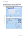
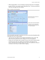
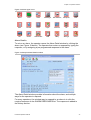
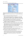
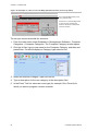
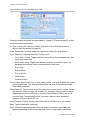
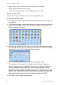
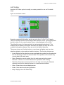
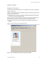
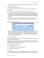
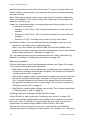
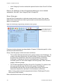
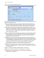
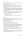
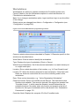
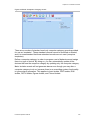
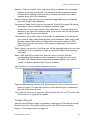
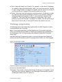
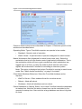
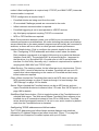
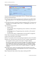
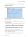
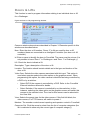
Figure 77: Network Configuration window (TCP/IP & Infleet)
Set the check box for the required node to enable TCP/IP addressing, and then
program the TCP/IP address used by the default interface for that node. It is not
possible to set the check box for the local node.
Note: When offsite redundancy is used, enter the IP address for the mirror site
(which will operate as node 1 when active) in the IP address fields for the highest
node number.
QNX normally operates on a LAN that has no routers (QNX packets are not
routable).
QNX 4 uses the following Ethernet protocol:
•
Ethernet 2.0 based on the DIX (Digital, Intel, Xerox) 2.0 specification
•
QNX 4 has an assigned ethertype of 0x8203
To use FLEET (which is the recommended method), the network should be
straight cable or routers or switches capable of passing the 0x8203 packets. If
this is not possible, the FLEET packets must be encapsulated into TCP/IP.
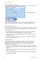
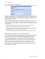
Configuring network details
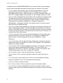
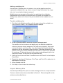
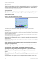
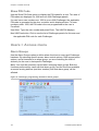
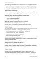
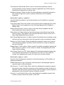
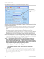
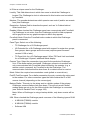
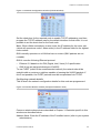
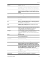
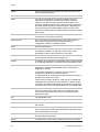
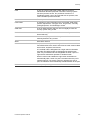
This is where the network configuration details for this node are programmed.
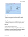
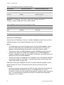
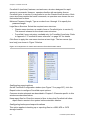
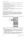
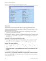
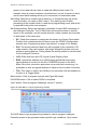
Figure 78: Interface Details window (example IP address used)
Common window elements are described in Chapter 3. Elements specific to this
window are described below.
Address fields. Enter the IP address of the Forcefield server (refer to your system
administrator).
Forcefield Operators Manual
241