1
4600 Series IP Telephone
Installation Guide
555-233-128
Issue 5
November 2006
© 2006 Avaya Inc.
All Rights Reserved.
Notice
While reasonable efforts were made to ensure that the information in this
document was complete and accurate at the time of printing, Avaya Inc. can
assume no liability for any errors. Changes and corrections to the information
in this document may be incorporated in future releases.
For full legal page information, please see the complete document, Avaya
Legal Page for Hardware Documentation, Document number 03-600759.
To locate this document on our Web site, simply go to
http://www.avaya.com/support and search for the document number in
the search box.
Documentation disclaimer
Avaya Inc. is not responsible for any modifications, additions, or deletions to
the original published version of this documentation unless such modifications,
additions, or deletions were performed by Avaya. Customer and/or End User
agree to indemnify and hold harmless Avaya, Avaya's agents, servants and
employees against all claims, lawsuits, demands and judgments arising out of,
or in connection with, subsequent modifications, additions or deletions to this
documentation to the extent made by the Customer or End User.
Link disclaimer
Avaya Inc. is not responsible for the contents or reliability of any linked Web
sites referenced elsewhere within this documentation, and Avaya does not
necessarily endorse the products, services, or information described or offered
within them. We cannot guarantee that these links will work all of the time and
we have no control over the availability of the linked pages.
Warranty
Avaya Inc. provides a limited warranty on this product. Refer to your sales
agreement to establish the terms of the limited warranty. In addition, Avaya’s
standard warranty language, as well as information regarding support for this
product, while under warranty, is available through the following Web site:
http://www.avaya.com/support
Copyright
Except where expressly stated otherwise, the Product is protected by copyright
and other laws respecting proprietary rights. Unauthorized reproduction,
transfer, and or use can be a criminal, as well as a civil, offense under the
applicable law.
Avaya support
Avaya provides a telephone number for you to use to report problems or to ask
questions about your product. The support telephone number
is 1-800-242-2121 in the United States. For additional support telephone
numbers, see the Avaya Web site:
http://www.avaya.com/support
Software License
USE OR INSTALLATION OF THE PRODUCT INDICATES THE END USER’S
ACCEPTANCE OF THE TERMS SET FORTH HEREIN AND THE GENERAL
LICENSE TERMS AVAILABLE ON THE AVAYA WEBSITE AT
http://support.avaya.com/LicenseInfo/ (“GENERAL LICENSE TERMS”). IF
YOU DO NOT WISH TO BE BOUND BY THESE TERMS, YOU MUST
RETURN THE PRODUCT(S) TO THE POINT OF PURCHASE WITHIN TEN
(10) DAYS OF DELIVERY FOR A REFUND OR CREDIT.
Avaya grants End User a license within the scope of the license types
described below. The applicable number of licenses and units of capacity for
which the license is granted will be one (1), unless a different number of
licenses or units of capacity is specified in the Documentation or other
materials available to End User. “Designated Processor” means a single
stand-alone computing device. “Server” means a Designated Processor that
hosts a software application to be accessed by multiple users. “Software”
means the computer programs in object code, originally licensed by Avaya and
ultimately utilized by End User, whether as stand-alone Products or
pre-installed on Hardware. “Hardware” means the standard hardware
Products, originally sold by Avaya and ultimately utilized by End User.
License Type(s):
Designated System(s) License (DS). End User may install and use each copy
of the Software on only one Designated Processor, unless a different number
of Designated Processors is indicated in the Documentation or other materials
available to End User. Avaya may require the Designated Processor(s) to be
identified by type, serial number, feature key, location or other specific
designation, or to be provided by End User to Avaya through electronic means
established by Avaya specifically for this purpose.
Third-party Components
Certain software programs or portions thereof included in the Product may
contain software distributed under third party agreements (“Third Party
Components”), which may contain terms that expand or limit rights to use
certain portions of the Product (“Third Party Terms”). Information identifying
Third Party Components and the Third Party Terms that apply to them is
available on Avaya’s Web site at:
http://support.avaya.com/ThirdPartyLicense/
Interference
Using a cell, mobile, or GSM telephone, or a two-way radio in close proximity to
an Avaya IP Telephone might cause interference.
Contents
Chapter 1: Introduction . . . . . . . . . . . . . . . . . . . . . . . . . . .
7
About This Guide . . . . . . . . . . . . . . . . . . . . . . . . . . . . . . . . . . .
7
Intended Audience. . . . . . . . . . . . . . . . . . . . . . . . . . . . . . . . . . .
8
Document Organization . . . . . . . . . . . . . . . . . . . . . . . . . . . . . . . .
8
Change History . . . . . . . . . . . . . . . . . . . . . . . . . . . . . . . . . . . .
9
What’s New in This Release. . . . . . . . . . . . . . . . . . . . . . . . . . . . . .
10
Terms Used in This Guide. . . . . . . . . . . . . . . . . . . . . . . . . . . . . . .
11
Conventions Used in This Guide . . . . . . . . . . . . . . . . . . . . . . . . . . .
Symbolic Conventions . . . . . . . . . . . . . . . . . . . . . . . . . . . . . .
Typographic Conventions. . . . . . . . . . . . . . . . . . . . . . . . . . . . .
12
12
12
Online Documentation. . . . . . . . . . . . . . . . . . . . . . . . . . . . . . . . .
13
Related Documents . . . . . . . . . . . . . . . . . . . . . . . . . . . . . . . . . .
13
Customer Support . . . . . . . . . . . . . . . . . . . . . . . . . . . . . . . . . . .
16
Chapter 2: 4600 Series IP Telephone Installation . . . . . . . . . . . . .
17
Introduction . . . . . . . . . . . . . . . . . . . . . . . . . . . . . . . . . . . . . .
IP Telephone Models . . . . . . . . . . . . . . . . . . . . . . . . . . . . . . .
Software . . . . . . . . . . . . . . . . . . . . . . . . . . . . . . . . . . . . . .
17
18
18
Pre-Installation Checklist . . . . . . . . . . . . . . . . . . . . . . . . . . . . . . .
19
Assembling the 4600 Series IP Telephone . . . . . . . . . . . . . . . . . . . . . .
Powering the 4600 IP Telephone . . . . . . . . . . . . . . . . . . . . . . . . .
22
22
Dynamic Addressing Process . . . .
Ethernet Activation . . . . . . . .
802.1X Supplicant Authentication
DHCP Processing . . . . . . . . .
TFTP/HTTP Processing . . . . . .
Media Server Registration. . . . .
.
.
.
.
.
.
36
37
37
38
39
40
Downgrading Avaya IP Telephones (H.323 Only) . . . . . . . . . . . . . . . . . .
41
Converting Software on Avaya 4600 Series IP Telephones . . . . . . . . . . . . .
Converting 4602+/4610SW/4620SW/4621SW IP Telephones . . . . . . . . . .
42
43
Unnamed Registration. . . . . . . . . . . . . . . . . . . . . . . . . . . . . . . . .
45
802.1X Supplicant Operation . . . . . . . . . . . . . . . . . . . . . . . . . . . . .
45
Chapter 3: Local Administrative Options . . . . . . . . . . . . . . . . .
47
Introduction . . . . . . . . . . . . . . . . . . . . . . . . . . . . . . . . . . . . . .
47
Entering Data for Administrative Options . . . . . . . . . . . . . . . . . . . . . .
48
Entering Data for the 4601 IP Telephone . . . . . . . . . . . . . . . . . . . . . . .
50
About Local Administrative Procedures . . . . . . . . . . . . . . . . . . . . . . .
51
.
.
.
.
.
.
.
.
.
.
.
.
.
.
.
.
.
.
.
.
.
.
.
.
.
.
.
.
.
.
.
.
.
.
.
.
.
.
.
.
.
.
.
.
.
.
.
.
.
.
.
.
.
.
.
.
.
.
.
.
.
.
.
.
.
.
.
.
.
.
.
.
.
.
.
.
.
.
.
.
.
.
.
.
.
.
.
.
.
.
.
.
.
.
.
.
.
.
.
.
.
.
.
.
.
.
.
.
.
.
.
.
.
.
.
.
.
.
.
.
.
.
.
.
.
.
.
.
.
.
.
.
.
.
.
.
.
.
Issue 5 November 2006
3
Contents
Set the 802.1X Operational Mode . . . . . . . . . . . . . . . . . . . . . . . . . . .
53
Pre-Installation Checklist for Static Addressing. . . . . . . . . . . . . . . . . . .
54
Static Addressing Installation. . . . . . . . . . . . . . . . . . . . . . . . . . . . .
54
Disable/Enable Automatic Gain Control . . . . . . . . . . . . . . . . . . . . . . .
58
Visual/Audible Alerting Procedure . . . . . . . . . . . . . . . . . . . . . . . . . .
59
Manually Setting the DHCP Client Hardware Address . . . . . . . . . . . . . . .
61
Clear Procedure . . . . . . . . . . . . . . . . . . . . . . . . . . . . . . . . . . . .
62
Adjusting the Contrast Control . . . . . . . . . . . . . . . . . . . . . . . . . . . .
64
Computer-Telephony Integration (CTI) Enable/Disable . . . . . . . . . . . . . . .
65
Enabling/Disabling the FKEU (XMOD) Interface . . . . . . . . . . . . . . . . . . .
66
Group Identifier . . . . . . . . . . . . . . . . . . . . . . . . . . . . . . . . . . . .
67
Interface Control . . . . . . . . . . . . . . . . . . . . . . . . . . . . . . . . . . . .
68
Disable/Enable Event Logging . . . . . . . . . . . . . . . . . . . . . . . . . . . .
71
Logoff. . . . . . . . . . . . . . . . . . . . . . . . . . . . . . . . . . . . . . . . . .
72
Turning Off the Backlight . . . . . . . . . . . . . . . . . . . . . . . . . . . . . . .
73
QoS Option Setting . . . . . . . . . . . . . . . . . . . . . . . . . . . . . . . . . .
73
Reset System Values . . . . . . . . . . . . . . . . . . . . . . . . . . . . . . . . .
75
Restart the Telephone . . . . . . . . . . . . . . . . . . . . . . . . . . . . . . . . .
77
Signaling Protocol Identifier . . . . . . . . . . . . . . . . . . . . . . . . . . . . .
78
Site-Specific Option Number Setting . . . . . . . . . . . . . . . . . . . . . . . . .
79
Setting L2Q Tagging Control (4601 Only) . . . . . . . . . . . . . . . . . . . . . .
81
Self-Test Procedure . . . . . . . . . . . . . . . . . . . . . . . . . . . . . . . . . .
82
Chapter 4: Troubleshooting Guidelines . . . . . . . . . . . . . . . . . .
85
Introduction . . . . . . . . . . . . . . . . . . . . . . . . . . . . . . . . . . . . . .
85
Error Conditions . . . . . . . . . . . . . . . . . . . . . . . . . . . . . . . . . . . .
DTMF Tones . . . . . . . . . . . . . . . . . . . . . . . . . . . . . . . . . . . .
Power Interruption . . . . . . . . . . . . . . . . . . . . . . . . . . . . . . . . .
85
86
86
The View Administrative Option . . . . . . . . . . . . . . . . . . . . . . . . . . .
87
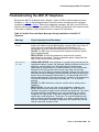
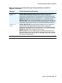
Error and Status Messages . . . . . . . . . . . . . . . . . . . . . . . . . . . . . .
90
Troubleshooting the 4601 IP Telephone . . . . . . . . . . . . . . . . . . . . . . .
95
Appendix A: Restart Scenarios . . . . . . . . . . . . . . . . . . . . . . .
99
Scenarios for the Restart Process . . . . . . . . . . . . . . . . . . . . . . . . . .
Restart the Telephone . . . . . . . . . . . . . . . . . . . . . . . . . . . . . . .
Boot File Needs to be Upgraded . . . . . . . . . . . . . . . . . . . . . . . . .
Latest Boot File Loaded/No Application File or
99
99
100
4 4600 Series IP Telephone Installation Guide
Contents
Index
Application File Needs to be Upgraded . . . . . . . . . . . . . . . . . . . . .
Latest Boot File and System-Specific
Application File Already Loaded . . . . . . . . . . . . . . . . . . . . . . . .
103
. . . . . . . . . . . . . . . . . . . . . . . . . . . . . . . . . .
107
105
Issue 5 November 2006
5
Contents
6 4600 Series IP Telephone Installation Guide
Chapter 1: Introduction
About This Guide
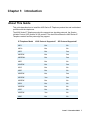
This guide describes how to install the 4600 Series IP Telephone product line and troubleshoot
problems with the telephones.
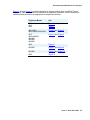
The 4600 Series IP Telephone product line supports two signaling protocols, the Session
Initiation Protocol (SIP) and the H.323 protocol. The chart below shows the 4600 Series IP
Telephone models and the protocol(s) they support.
IP Telephone Model
H323 Protocol Supported?
SIP Protocol Supported?
4601
Yes
No
4601+
Yes
No
4602
Yes
Yes
4602SW
Yes
Yes
4602SW+
Yes
Yes
4606
Yes
No
4610SW
Yes
Yes
4612
Yes
No
4620
Yes
No
4620SW
Yes
Yes
4621SW
Yes
Yes
4622SW
Yes
No
4624
Yes
No
4625SW
Yes
No
4630
Yes
No
4630SW
Yes
No
4690
Yes
No
Issue 5 November 2006
7
Introduction
Sets that support both protocols, for example, the 4610SW, do not support each protocol
simultaneously. Instead, a given telephone must be loaded with software that supports one
protocol or the other.
Telephones with H.323 software work only with Avaya Communication Manager call servers.
Telephones with SIP software are supported only in Avaya server environments.
Note:
Note:
Unless otherwise indicated, references in this document to the DEFINITY®
servers also refer to MultiVantage™ media servers.
Intended Audience
This document is intended for personnel who install the 4600 Series IP Telephones.
! CAUTION:
CAUTION:
Avaya does not support many of the products mentioned in this document. Take
care to ensure that there is adequate technical support available for the servers
involved, including, but not necessarily limited to, TFTP, DHCP, and SIP
Registration servers. If the TFTP, DHCP, or other servers are not functioning
correctly, the IP telephones might not be able to operate correctly.
Document Organization
The guide contains the following sections:
Chapter 1: Introduction
Provides an overview of the 4600 Series IP Telephone
Installation Guide.
Chapter 2: 4600 Series IP
Telephone Installation
Describes the equipment and resources required to properly
install and operate the 4600 Series IP Telephones. Provides
instructions on installing the telephones out of the box.
Chapter 3: Local
Administrative Options
Describes how to set local administrative options, if requested by
the system or LAN administrator.
Chapter 4: Troubleshooting
Guidelines
Describes error conditions and messages that might occur
during the installation of the 4600 Series IP Telephones.
Appendix A: Restart
Scenarios
Explains the different scenarios possible for the sequence of the
restart process.
8 4600 Series IP Telephone Installation Guide
Change History
Change History
Issue 1.0
This document was issued for the first time in November 2000.
Issue 1.1
This version of the document, revised and issued in April 2001, supports through
DEFINITY® Release 9.
Issue 1.5
This version of the document, revised and issued in June, 2001, supports through
DEFINITY® Release 9.5.
Issue 1.6
This version of the document, revised and issued in December, 2001, supports through
DEFINITY® Release 10. This version also supports the 4630 IP Telephone’s addition to
the 4600 Series IP Telephone product line.
Issue 1.7
This version of the document, issued in July, 2002, supports through Avaya
Communication Manager Release 1.1. This version also supports the 4602 and 4620 IP
Telephones’ addition to the 4600 Series IP Telephone product line.
Issue 1.8
This version of the document, revised and issued in June, 2003, supports through Avaya
Communication Manager Releases 1.2 and 1.3. This version also supports the 4602SW
and 4630SW IP Telephones’ addition to the 4600 Series IP Telephone product line.
Issue 2.0
This version of the document, revised and issued in December, 2003, supports through
Avaya Communication Manager Release 2.0. This version also supports the addition of
the 4610SW and 4620SW IP Telephones, and the 4690 IP Conference Telephone to the
4600 Series IP Telephone product line.
Issue 2.1
This version of this document was revised and issued in July, 2004. This version
supports through Avaya Communication Manager Release 2.1. This version also
introduces the 4601 IP Telephone.
Issue 2.2
This version of this document was revised and issued in April, 2005. This version
supports through Avaya Communication Manager Release 2.2. This version also
introduces the 4621SW, 4622SW, and 4625SW IP Telephones.
Issue 2.2.1
This version was revised and issued in August, 2005. This version introduces the SIP IP
telephones.
Issue 3
This version was revised and issued in April, 2006. This version supports through Avaya
Communication Manager Release 3.1. This version introduces unnamed registration
and three local procedures, LOG, AGC, and FKEU.
Issue 4
This version was revised and issued in August, 2006. This version supports through
Avaya Communication Manager Release 3.1 and IP Telephone Software Release 2.6.
This version introduces 802.1X Supplicant support, Link Layer Discovery Protocol
(LLDP), and power conservation mode. This issue introduces new telephone models
4601+ and 4602SW+, which replace the 4601 and 4602/4602SW, respectively, from
Release 2.6 and up.
Issue 5
This is the current version of this document, revised and issued in November, 2006. This
version supports through Avaya Communication Manager Release 3.1 and IP Telephone
Software Release 2.7. This version introduces additional Unicode languages, support for
dialpad-activated Web links, the capability to turn off the display backlight, several new
system parameters, and two new local procedures.
Issue 5 November 2006
9
Introduction
What’s New in This Release
New material in this issue to support Release 2.7 software includes:
●
4625SW IP Telephones now support all the applications and functionality that 4620/
4620SW IP Telephones have supported since Software Release 2.1. Differences are that
the 4625 has a color 1/4-VGA display, has a slightly different stand, and does not have an
infrared (IR) interface.
●
Support for the following Unicode languages on the 4625SW IP Telephone:
- Simplified Chinese,
- Korean,
- Russian, and
- Hebrew.
●
Two new local administrative procedures:
- Mute C O N T # - to allow users to adjust telephone display contrast, and
- Mute O F F # - to immediately turn off the display backlight.
●
New system parameters FTPDIR, FTPSRVR, FTPUSERSTAT, UNNAMEDSTAT,
QKLOGINSTAT, BAKLIGHTOFF, HEADSYS, WMLIDLETIME, and WMLIDLEURI. For
more information, see the 4600 Series IP Telephone LAN Administrator Guide (Document
Number 555-233-507).
●
Support for the 4601+ and 4602SW+ IP Telephones, which replace the 4601, 4602, and
4602SW IP Telephones, respectively. Release 2.7 does not support the 4601, 4602, and
4602SW IP Telephones.
●
The 4610SW, 4620SW, 4621SW, 4622SW IP Telephones now support the Korean
language.
10 4600 Series IP Telephone Installation Guide
Terms Used in This Guide
Terms Used in This Guide
802.1Q
802.1D
802.1X
ARP
CLAN
DHCP
DiffServ
IETF
LAN
LLDP
MAC
PAE
QoS
RRQ
SES
SIP
Supplicant
TCP/IP
TFTP
UDP
Unnamed
Registration
VLAN
802.1Q defines a layer 2 frame structure that supports VLAN identification and a QoS
mechanism usually referred to as 802.1D.
Authentication method for a protocol requiring a networking device to authenticate
with a back end Authentication Server before gaining network access. Applicable
4600 Series IP telephones support IEEE 802.1X as a Supplicant with the EAP-MD5
authentication method.
Address Resolution Protocol, used to verify that the IP Address provided by the
DHCP server is not in use by another IP telephone.
Control LAN, type of TN799 circuit pack.
Dynamic Host Configuration Protocol, an IETF protocol used to automate IP Address
allocation and management.
Differentiated Services, an IP-based QoS mechanism.
Internet Engineering Task Force, the organization that produces standards for
communications on the internet.
Local Area Network.
Link Layer Discovery Protocol. All IP Telephones with an Ethernet interface support
the transmission and reception of LLDP frames on the Ethernet line interface in
accordance with IEEE standard 802.1AB.
Media Access Control, ID of an endpoint
Port Access Entity. The protocol entity associated with a port. The PAE supports the
protocol functionality associated with the authenticator, supplicant, or both.
Quality of Service, used to refer to several mechanisms intended to improve audio
quality over packet-based networks.
Read Request packet. A message sent from the 4600 Series IP Telephone to the
TFTP server, requesting to download the upgrade script and the application file.
SIP Enablement Services. Supports the deployment of duplicated servers with
synchronized databases.
Session Initiation Protocol. An IETF standard protocol for IP communication. SIP
enables IP telephony gateways, client endpoints, PBXs, and other communication
systems or devices to communicate with each other. SIP mainly addresses the call
setup and tear down mechanisms of sessions and is independent of the transmission
of media streams between caller and callee. SIP is an alternative to H.323 for VoIP
signaling.
An entity at one end of a point-to-point LAN segment that is being authenticated by
an authenticator at the other end of that link.
Transmission Control Protocol/Internet Protocol, a network-layer protocol used on
LANs and internets.
Trivial File Transfer Protocol, used to provide downloading of upgrade scripts and
application files to the IP telephones.
User Datagram Protocol, a connectionless transport-layer protocol.
Registration with Avaya Communication Manager by an IP telephone with no
extension. Unnamed registration is typically used to limit outgoing calling.
Virtual LAN.
Issue 5 November 2006
11
Introduction
Conventions Used in This Guide
This guide uses the following textual, symbolic, and typographic conventions to help you
interpret information.
Symbolic Conventions
Note:
Note:
This symbol precedes additional information about a topic. This information is not
required to run your system.
! CAUTION:
CAUTION:
This symbol emphasizes possible harm to software, possible loss of data, or
possible service interruptions.
Typographic Conventions
This guide uses the following typographic conventions:
command
Words printed in this type are commands that you enter into your
system.
Message
Words printed in this type are system messages.
device
Words printed in this type indicate parameters associated with a
command for which you must substitute the appropriate value.
For example, when entering the mount command, device must
be replaced with the name of the drive that contains the
installation disk.
Administrative
Words printed in bold type are menu or screen titles and labels.
Bold type words can also be items on menus or screens that you
should select or enter to perform a task, i.e., fields, buttons, or
icons. Bold text is also used for general emphasis.
italics
Italic type indicates a document that contains additional
information about a topic.
12 4600 Series IP Telephone Installation Guide
Online Documentation
Online Documentation
The online documentation for the 4600 Series IP Telephones is located at the following URL:
http://www.avaya.com/support
Related Documents
●
DEFINITY® ECS (Enterprise Communication Server) Documentation Release 8.4
This document describes how to administer a DEFINITY ECS switch with Release 8.4
software.
●
DEFINITY® ECS (Enterprise Communication Server) Documentation Release 9
This document describes how to administer a DEFINITY ECS switch with Release 9
software.
●
DEFINITY® ECS (Enterprise Communication Server) Documentation Release 10
This document describes how to administer a DEFINITY ECS switch with Release 10
software.
●
Avaya Communication Manager Software Documentation Release 1.1
This document describes how to administer a switch with Avaya MultiVantage
(Release 1.1) software.
●
Avaya Communication Manager Software Documentation Release 1.2
This document describes how to administer a switch with Avaya Communication
Manager (Release 1.2) software.
●
Avaya Communication Manager Software Documentation Release 1.3
This document describes how to administer a switch with Avaya Communication
Manager (Release 1.3) software.
●
Avaya Communication Manager Software Documentation Release 2.0
This document describes how to administer a switch with Avaya Communication
Manager (Release 2.0) software.
●
Avaya Communication Manager Software Documentation Release 2.1
This document describes how to administer a switch with Avaya Communication
Manager (Release 2.1) software.
Issue 5 November 2006
13
Introduction
●
Avaya Communication Manager Software Documentation Release 2.2
This document describes how to administer a switch with Avaya Communication
Manager (Release 2.2) software.
●
Avaya Communication Manager Software Documentation Release 3.0
This document describes how to administer a switch with Avaya Communication
Manager (Release 3.0) software.
●
Avaya Communication Manager Software Documentation Release 3.1
This document describes how to administer a switch with Avaya Communication
Manager (Release 3.1) software.
●
Converged Communication Server Installation and Administration Guide (555-245-705)
This document describes how to install and administer the Converged Communication
Server with the latest CCS software release.
●
SIP Support in Release 3.0 of Avaya Communication Manager running on the Avaya
S8300, S8500, and 8710 Media Server (555-245-206)
This document describes requirements and introduces procedures for administering SIP
(Session Initiation Protocol) with Avaya Communication Manager Release 3.0.
●
Avaya IP Telephone File Server Application Reference Guide (16-601433)
This document describes how to install and implement the File Server Application for IP
Telephones.
●
Avaya IP Telephone SNMP Security White Paper, Issue 0.1
This document has extensive information about SNMP and related Release 2.6 changes.
●
4600 Series IP Telephone Safety Instructions (555-233-779)
This document contains important user safety instructions for the 4600 Series IP
Telephones.
●
30A Switched Hub Set Up Quick Reference, Issue 2, July 2002 (555-236-700)
This document contains important safety and installation information for the
30A Switched Hub.
●
4600 Series IP Telephone LAN Administrator Guide (555-233-507)
This document describes how to administer DHCP, TFTP, SIP Registration, and other
servers as appropriate for the 4600 Series IP and SIP IP Telephones. It also provides
troubleshooting guidelines for the 4600 Series IP and SIP IP Telephones and for the
DHCP and TFTP servers. The LAN Administrator Guide contains information on how to
administer advanced applications for the 4610SW, 4620/4620SW/4621SW/4622SW/
4625SW, 4630/4630SW, and 4690 IP Telephones.
●
4601 IP Telephone User Guide (16-300043)
This document provides detailed information about using the 4601 and 4601+ IP
Telephones.
14 4600 Series IP Telephone Installation Guide
Related Documents
●
4602/4602SW IP Telephone User Guide (555-233-780)
This document provides detailed information about using the 4602/4602SW/4602+ IP
Telephones.
●
4602/4602SW SIP IP Telephone User Guide (16-300470)
This document provides detailed information about using the 4602/4602SW SIP IP
Telephone.
●
4606 IP Telephone User Guide (555-233-775)
This document provides detailed information about using the 4606 IP Telephone.
●
4610SW IP Telephone User Guide (555-233-784)
This document provides detailed information about using the 4610SW IP Telephone.
●
4610SW SIP IP Telephone User Guide (16-300472)
This document provides detailed information about using the 4610SW SIP IP Telephone.
●
4612 IP Telephone User Guide (555-233-777)
This document provides detailed information about using the 4612 IP Telephone.
●
4620/4620SW/4621SW IP Telephone User Guide (555-233-781)
This document provides detailed information about using the 4620/4620SW and
4621SW IP Telephones.
●
4620SW/4621SW SIP IP Telephone User Guide (16-300474)
This document provides detailed information about using the 4620SW and 4621SW SIP
IP Telephones.
●
4622SW IP Telephone User Guide (16-300297)
This document provides detailed information about using the 4622SW IP Telephone.
●
4624 IP Telephone User Guide (555-233-776)
This document provides detailed information about using the 4624 IP Telephone.
●
4625SW IP Telephone User Guide (16-300298)
This document provides detailed information about using the 4625SW IP Telephone.
●
4630/4630SW IP Telephone User Guide (555-233-764)
This document provides detailed information about using the 4630/4630SW IP
Telephone.
●
Avaya 4690 IP Conference Telephone User Guide (555-233-787)
This document provides detailed information about using the 4690 IP Conference
Telephone.
Issue 5 November 2006
15
Introduction
●
4601/4602/4602SW IP Telephone Stand Instructions (555-233-147)
This document provides information on how to desk- or wall-mount a
4601 or 4602/4602SW IP Telephone and a 4602/4602SW SIP IP Telephone.
●
4610SW IP Telephone Stand Instructions (555-233-165)
This document provides information on how to desk- or wall-mount a
4610SW IP or SIP IP Telephone.
●
4620/4620SW/4621SW/4622SW/4625SW IP Telephone Stand Instructions (16-300299)
This document provides information on how to mount a 4620/4620SW/4621SW/
4622SW/4625SW IP or 4620SW/4621SW SIP IP Telephone on a wall.
●
EU24/EU24BL Expansion Module User Guide (555-250-702)
This document provides detailed information about the EU24/EU24BL Expansion
Module. The EU24/EU24BL is an optional attachment that provides additional Feature
buttons for the 4620/4620SW, 4621SW, 4622SW, or 4625SW IP Telephones.
●
EU24/EU24BL Installation and Safety Instructions (555-233-136)
This document provides detailed installation instructions for the EU24/EU24BL
Expansion Module.
Customer Support
For 4600 Series IP Telephone support, call the Avaya support number provided to you by your
Avaya representative or Avaya reseller.
Information about Avaya products can be obtained at the following URL:
http://www.avaya.com/support
16 4600 Series IP Telephone Installation Guide
Chapter 2: 4600 Series IP Telephone Installation
Introduction
The 4600 Series IP Telephone product line uses Internet Protocol (IP) technology with Ethernet
interfaces. The IP telephones supplement the existing DEFINITY®/MultiVantage™ IP Solutions
platform.
The 4600 Series IP Telephones support DHCP and TFTP over IPv4/UDP which enhance the
administration and servicing of the telephones. These telephones use DHCP to obtain dynamic
IP Addresses and TFTP or HTTP/HTTPS to download new software versions for the
telephones.
Most 4600 Series IP Telephones provide the ability to have one IP connection on the desktop
for both a telephone set and a PC. The 4606, 4612, 4624, and 4630 IP Telephones provide a
repeater. The 4602SW, 4602SW+, 4610SW, 4620, 4620SW, 4621SW, 4622SW, 4625SW, and
4630SW IP Telephones, and the 30A switched hub, provide an Ethernet switch. The 4601,
4601+, and 4602 IP Telephones, and the 4690 IP Conference Telephone, have neither a
repeater nor a switch, and cannot share a port with a PC.
Note:
Note:
For information on Voice over IP, see the 4600 Series IP Telephone LAN
Administrator Guide.
In compliance with Australian law, the following information is provided:
This equipment shall be installed and maintained by trained service personnel. All the input/
output ports are classified as Safety Extra Low Voltage (SELV, in the meaning of IEC
60950). To maintain safety compliance when connecting the equipment electrically to other
equipment, the interconnecting circuits shall be selected to provide continued conformance
of clause 2.3 for SELV circuits (generally, double/reinforced insulation to 240Vac rms to any
primary/mains circuitry and 120Vac rms to any telecommunications network circuitry). To
ensure that these conditions are adhered to, interconnect the equipment only with the
already approved/certified equipment.
Issue 5 November 2006
17
4600 Series IP Telephone Installation
IP Telephone Models
There are seventeen telephone set models defined in the 4600 Series IP Telephone family:
●
●
●
●
●
●
4601 IP
Telephone
4601+ IP
Telephone
4602 IP
Telephone
4602SW IP
Telephone
4602SW+ IP
Telephone
4606 IP
Telephone
●
●
●
●
●
●
4610SW IP
Telephone
4612 IP
Telephone
4620 IP
Telephone
4620SW IP
Telephone
4621SW IP
Telephone
4622SW IP
Telephone
●
●
●
●
●
4624 IP
Telephone
4625SW IP
Telephone
4630 IP
Telephone
4630SW IP
Telephone
4690 IP
Conference Telephone
Telephone models containing the SW designation have the same appearance, user interface,
and functionality as their non-SW counterparts, with one exception. The telephones have an
internal Ethernet switch that allows the telephone and a PC to share the same LAN connection,
if appropriate. Thus, SW models do not need, or work with, the 30A switched hub interface. The
exception to this exception is the 4620—both the 4620 and 4620SW, and other 46xx Series IP
Telephones aliased as a 4620 contain an Ethernet switch.
Additionally, the 4630SW IP Telephone differs from the 4630 IP Telephone in two distinct ways.
The 4630SW can be LAN-powered and is FCC and CISPR Class B. The 4630 is a Class A
device that does not support LAN powering.
Telephone models with a + designation have the same appearance, user interface, and
functionality as their non-plus counterparts. The + telephone models have twice as much
memory and are RoHS-compliant (lead-free).
This document describes the installation of these telephones. For details about using the
features provided by the telephones, see the user documentation for each telephone. For
information about desk or wall mounting any of the 4600 IP Telephone Series, see the
instructions boxed with the telephone. Wall or desk mount instructions are also available on the
Avaya support Web site.
Software
As shipped from the factory, the 4600 Series IP Telephones may not contain sufficient software
for registration and operation. When the telephone is first plugged in, a software download from
a TFTP or HTTP server is initiated. The software download gives the telephone the functionality
of an Avaya IP Telephone.
18 4600 Series IP Telephone Installation Guide
Pre-Installation Checklist
For downloads of software upgrades, the Avaya Media Server provides the capability for a
remote restart of the IP telephone. As a consequence of restarting, the telephone automatically
restarts reboot procedures which result in a download if new software is available.
Pre-Installation Checklist
Before plugging in the 4600 Series IP Telephone, verify that all the following requirements are
met. Failure to do so prevents the telephone from working and can have a negative impact on
the network. Print copies of this checklist for each server and IP telephone.
Requirements to Verify about the Network
1.
This first checklist item applies only to H.323 telephones. The Avaya Media Server is
administered for IP telephones and has software for Release 8.4 or later. Avaya
Communication Manager Release 1.1 supports the 4602 and 4620/4620SW IP
Telephones. The recommended configuration is the latest PBX software and the latest IP
telephone firmware. In the event you are installing at a site without the latest PBX software,
follow these recommendations:
Media Server
Avaya IP
IP Telephone
Release
Telephone
Release
Notes
All
R2.6+
IP Telephone software Release 2.7
Avaya
Communication
telephones
does not support the 4601, 4602,
Manager 3.1+
and 4602SW.
Avaya
All
R1.8+
Use the latest release.
Communication
telephones
Manager 1.3+
Avaya
All
R1.8+
Use the latest release.
Communication
telephones
Manager 1.1,
except 4630
Avaya
Communication
Manager 1.2
R10, Avaya
4630
R1.74
Upgrade to Avaya Communication
Communication
Manager Release 1.3 or later
Manager 1.1,
before installing R1.8 on 4630
Avaya
Telephones.
Communication
Manager 1.2
R10
4606, 4612,
R1.8+
The 4602 and 4620 are not
4624
supported.
R9.5
4606, 4612,
R1.8+
The 4620, 4602, and 4630 are not
4624
supported. R1.5 is the minimum
4600 IP Telephone vintage.
R9
4612, 4624
R1.1
R1.1 is the only supported 4600 IP
Telephone vintage.
R8.4
4612, 4624
R1.0
R1.0 is the only supported 4600 IP
Telephone vintage.
Issue 5 November 2006
19
4600 Series IP Telephone Installation
! CAUTION:
CAUTION:
Using IP telephones on R8.4 or R9 requires extreme caution. You would be
downgrading the telephones to these very old releases. Downgrading any Avaya IP
Telephone other than the 4612 or 4624 to these old releases has not been tested and
might damage the telephone. See Downgrading Avaya IP Telephones (H.323 Only) on
page 41 for instructions on how to downgrade the software for Avaya IP Telephones.
Note: The 4621SW and 4625SW can be aliased as a 4620 on any call server that supports the
4620. In addition, Avaya Communication Manager Release 2.2 provides limited native support for
the 4621SW and 4625SW. See the Avaya Communication Manager Release 2.2 administration
documentation for more details.
Release 1.8 software changed the way the 4630 and 4630SW obtain administered Feature button
labels from the Media Server. Therefore, you must have Avaya Communication Manager Release
1.2 for 4630 IP Telephone Release 1.8 to work properly.
Requirements to Verify about the Network (continued)
2.
The following two circuit packs are installed on the switch:
●
TN2302 IP Media Processor circuit pack.
●
TN799B, C, or D Control-LAN (C-LAN) circuit pack.
!
Important:
3.
4.
5.
6.
7.
8.
9.
Note:
Important:
IP Telephone firmware Release 2.3 or greater requires TN799C V3 or
greater C-LAN circuit pack(s). For more information, see the
Communication Manager Software and Firmware Compatibility Matrix on
the Avaya support Web site http://www.avaya.com/support.
Note: Checklist item 2 applies only to H.323 telephones.
The Avaya Media Server is configured correctly, as described in the documentation listed
in Related Documents on page 13.
Note: This checklist item applies only to H.323 telephones.
The DHCP server and application are administered as described in the 4600 Series IP
Telephone LAN Administrator Guide.
The TFTP or HTTP server and application are administered as described in the 4600
Series IP Telephone LAN Administrator Guide.
The upgrade script and application files from the Avaya Support Web site are loaded
correctly on the TFTP server.
If applicable, the LDAP and DNS servers are administered as described in the 4600 Series
IP Telephone LAN Administrator Guide. This is a consideration only for 4610SW/4620/
4620SW/4621SW/4622SW/4625SW, and 4630/4630SW installations.
If applicable, the Voice Mail and/or Web Messaging servers are administered as described
in the 4600 Series IP Telephone LAN Administrator Guide. This is a consideration only for
4630/4630SW installations.
If applicable, the WML server is administered as described in the 4600 Series IP
Telephone LAN Administrator Guide. This is a consideration only for 4610SW and 4620/
4620SW/4621SW/4622SW/4625SW installations.
Note:
Any or all of the servers mentioned in items 4.-9. can be co-resident on the same
hardware.
20 4600 Series IP Telephone Installation Guide
Pre-Installation Checklist
Requirements to Verify for Each IP Telephone
10a.
10b.
10c.
11.
12.
Note:
You have an extension number and an Avaya Communication Manager security code
(password) for each IP telephone.
Note: This checklist item applies only to H.323 telephones. However, to allow an H.323
telephone user to sign on to a SIP telephone, you must also establish that person’s User
ID and password on the SIP Enablement Services (SES) server.
You have an OPTIM extension number and an Avaya Communication Manager security
code (password) for each SIP telephone. You have configured SIP Enablement Services
for each SIP telephone.
Note: This checklist item applies only to SIP telephones. However, to allow a SIP
telephone user to sign on to an H.323 telephone, you must also establish that person’s
User ID and password on Avaya Communication Manager.
You have an 802.1X Supplicant Identity and password for each IP telephone (H.323 only)
if applicable to your environment. The MAC address of the telephone will be used as a
default ID and the default password will be Null if you do not provide values. For more
information, see 802.1X Supplicant Authentication on page 37.
A Category 5e LAN jack is available at each telephone site.
Electrical power is provided to each telephone by a Telephone Power Module (DC power
jack) (must be ordered separately). If the LAN will supply IEEE-standard power to the
4601/4602/4602SW/4606/4610SW/4612/4620/4620SW/4621SW/4622SW/4624/
4625SW/4630SW, no power module is required.
Note:
The 4630 IP Telephone does not support IEEE-standard power, and therefore requires
the Power Module.
The 4690 IP Conference Telephone is powered with a special LAN/power cable with a
power interface module included with this telephone.
13. 1 Category 5e modular line cord is available for the connection between the IP telephone
and the PC.
14. Verify that the 4600 Series IP Telephone package includes the following components:
● 1 telephone set
● 1 telephone handset, except the 4622SW and 4690 IP Conference Telephones
● 1 H4DU 9-foot long (when extended) 4-conductor coiled handset cord, plugged into
the telephone and the handset, except the 4690 IP Conference Telephone
● 1 Category 5 modular line cord for the connection from the IP telephone to the
Ethernet wall jack
● 4600 Series IP Telephone Safety Instructions (555-233-779)
● Power Brick for 4630 IP Telephones only
● Stylus for 4630/4630SW IP Telephones only
● Power Interface Module for the 4690 IP Conference Telephone only
15. IP telephones ship from the factory with H.323 software. Existing installations might also
have many IP telephones running H.323 software. For instructions on how to convert
between H.323 and SIP software, see Converting Software on Avaya 4600 Series IP
Telephones on page 42.
Optional Items for Some IP Telephones
16.
If applicable to your current installation, verify that the following equipment/information is
present:
● 30A Switched Hub (applicable to the 4612/4624/4630 only)
● Stand Instructions, packaged with certain IP telephones
Issue 5 November 2006
21
4600 Series IP Telephone Installation
Assembling the 4600 Series IP Telephone
! CAUTION:
CAUTION:
Be careful to use the correct jack when plugging in the telephone. The jacks are
located on the back of the telephone housing and are flanked by icons to
represent their correct use.
Powering the 4600 IP Telephone
With one exception, there are two options to power 4600 Series IP Telephones. There is only
one way to power the 4630 IP Telephone. All 4600 Series IP Telephones can be locally powered
with a Telephone Power Module (DC power jack), available separately. In addition, the 4601/
4601+/4602/4602SW/4602SW+/4606/4610SW/4612/4620/4620SW/4621SW/4622SW/4624/
4625SW/4630SW IP Telephones support IEEE 802.3af-standard LAN-based power. Before
installation, verify with the LAN administrator whether the LAN supports IEEE 802.3af, and if so,
whether the telephone should be powered locally or by means of the LAN.
The 4690 IP Conference Telephone is powered using a power interface module placed between
the LAN and the telephone on the Category 5 network cable.
Note:
Note:
If your installation includes a 30A Switched Hub, follow the installation
instructions included in the Switched Hub box.
The last step in assembling the 4600 Series IP Telephone must be applying
power. Apply power either by plugging the power cord into the power source
(local powering) or plugging the modular line cord into the Ethernet wall jack
(IEEE powering).
! CAUTION:
CAUTION:
Failure to connect the proper cables with the proper jacks might result in an
outage in part of your network.
22 4600 Series IP Telephone Installation Guide
Assembling the 4600 Series IP Telephone
Figure 1 through Figure 11 provide illustrations to connect cords to jacks on 4600 IP Series
Telephones. See the chart below to determine the applicable illustration. Use the illustrations
and associated procedures as appropriate for telephone assembly.
Telephone Model:
See:
4606
4612
4624
Figure 1
Figure 1
Figure 1
4601/4601+
4602/4602SW/4602SW+
Figure 2 and Figure 3
4610
4620/4620SW
4621SW
4622SW
4625SW
Figure 4 and Figure 5
4630
Figure 6
4630SW
Figure 7 and Figure 8
4610SW
Figure 9 and Figure 10
4690
Figure 11
Issue 5 November 2006
23
4600 Series IP Telephone Installation
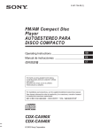
Figure 1: Connection Jacks on a 4606/4612/4624 IP Telephone
DC
See Note
= optional
facultatif
optionale
i
l
(DSS 4624)
24 4600 Series IP Telephone Installation Guide
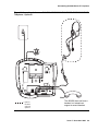
Assembling the 4600 Series IP Telephone
1. Plug one end of the H4DU 4-conductor coiled handset cord into the telephone and the other
end into the handset.
2. Plug one end of the first Category 5 modular line cord into the Ethernet jack of the PC and
the other end into the secondary Ethernet jack on the 4600 Series IP Telephone, if
appropriate.
Note:
Note:
The 4602SW/4602SW+ may have PC and LAN jacks reversed from their
pictures. Ensure that you make the right connections to the right equipment, as
noted by the icons on the telephone jacks.
3. Plug one end of the second Category 5 modular line cord into the Ethernet jack on the 4600
Series IP Telephone. Plug the other end of this cord into the Ethernet wall jack. If the
telephone is to be IEEE-powered, you are finished. Do not proceed to Step 4.
4. If the telephone is to be powered locally in the United States and Canada, plug the
power cord into the 4600 Series IP Telephone, and the power cord plug into the wall socket.
If the telephone is to be powered locally outside the United States and Canada,
connect the 1151 power brick to the power cable. Connect the other end of the power cable
to the 4600 Series IP Telephone, and the plug to the wall socket.
Issue 5 November 2006
25
4600 Series IP Telephone Installation
Figure 2: Connection Jacks on a 4601/4601+/4602/4602SW/4602SW+ IP Telephone Option A
1151B
= optional
facultatif
optionale
opcional
(DSS 4624)
26 4600 Series IP Telephone Installation Guide
Assembling the 4600 Series IP Telephone
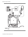
Figure 3: Connection Jacks on a 4601/4601+/4602/4602SW/4602SW+ IP Telephone Option B
= optional
facultatif
optionale
opcional
(DSS 4624)
Issue 5 November 2006
27
4600 Series IP Telephone Installation
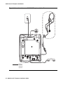
Figure 4: Connection Jacks on a 4610/4620/4620SW/4621SW/4622SW/4625SW/4630SW IP
Telephone - Option A
1151B
Note:
= optional
facultatif
optionale
opcional
28 4600 Series IP Telephone Installation Guide
Note:
The 4622SW does not have a
handset, but instead can
support a second headset.
Assembling the 4600 Series IP Telephone
Figure 5: Connection Jacks on a 4610/4620/4620SW/4621SW/4622SW/4625SW/4630SW IP
Telephone - Option B
Note:
= optional
facultatif
optionale
opcional
Note:
The 4622SW does not have a
handset, but instead can
support a second headset.
Issue 5 November 2006
29
4600 Series IP Telephone Installation
Figure 6: Connection Jacks on a 4630 IP Telephone
DC
= optional
facultatif
optionale
opcional
30 4600 Series IP Telephone Installation Guide
Assembling the 4600 Series IP Telephone
Figure 7: Connection Jacks on a 4630SW IP Telephone - Option A
1151B
= optional
facultatif
optionale
opcional
Issue 5 November 2006
31
4600 Series IP Telephone Installation
Figure 8: Connection Jacks on a 4630SW IP Telephone - Option B
= optional
facultatif
optionale
opcional
32 4600 Series IP Telephone Installation Guide
Assembling the 4600 Series IP Telephone
Figure 9: Connection Jacks on a 4610SW IP Telephone - Option A
Issue 5 November 2006
33
4600 Series IP Telephone Installation
Figure 10: Connection Jacks on a 4610SW IP Telephone - Option B
34 4600 Series IP Telephone Installation Guide
Assembling the 4600 Series IP Telephone
Figure 11: Connection Jacks on a 4690 IP Conference Telephone
DC
= optional
facultatif
optionale
opcional
Issue 5 November 2006
35
4600 Series IP Telephone Installation
Dynamic Addressing Process
Note:
Note:
For IP telephones supporting the H.323 protocol, before starting this process you
must have an extension number for the IP telephone and the Avaya
Communication Manager security code (password) for that extension. An
exception is when unnamed registration is enabled, which requires neither an
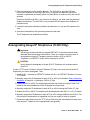
extension nor password entry. For more information, see Unnamed Registration.
For IP telephones supporting the SIP protocol, before starting this process you
must have an OPTIM extension number for the SIP telephone, the Avaya
Communication Manager security code (password), and a login and password on
the SES server.
The following description of the process of installing the IP telephones assumes that the
process is executed successfully. Only an initial out of the box installation is described. For
errors that might be encountered during the process and the messages displayed, see
Chapter 4: Troubleshooting Guidelines.
Note:
Note:
Dynamic addressing is the only way to establish addressing parameters on the
4601/4601+ IP Telephones. Because it lacks a display, this telephone uses its
LEDs to provide status indication. The instructions indicate processing
exceptions or elaborations specifically for 4601 IP Telephones where applicable,
and apply equally to the 4601+ IP Telephone.
When you plug the IP telephone set into the Ethernet wall jack and apply power, if applicable,
the following process takes place.
Note:
Note:
If the application has already been downloaded, the whole process takes
approximately 1 to 2 minutes after the telephone is plugged in. For an initial
installation, including the application download, the process might take 5 - 10
minutes. The duration is based on LAN loading, how many telephones are being
installed at once, and similar factors.
Do not unplug the power cord during the download process.
36 4600 Series IP Telephone Installation Guide
Dynamic Addressing Process
Ethernet Activation
The telephone activates the Ethernet line interface, the PC Ethernet jack, and dial pad input
to allow the invocation of procedures. The activation occurs as soon as possible after
power-up or a reset.
The telephone detects and displays the speed of the Ethernet interface in Mbps, that is,
10 or 100. The message No Ethernet displays until the software determines whether the
interface is 10 Mbps or 100 Mbps.
For the 4601/4601+ only, all the LED indicators illuminate to indicate system value
initialization. When system value initialization completes, the 4601’s Call Appearance Line a
flashes continuously 500 milliseconds on, 500 milliseconds off while all other LEDs remain
lit.
Note:
Note:
The Ethernet speed indicated is the LAN interface speed for both the telephone
and any attached PC.
802.1X Supplicant Authentication
If applicable, the 4602SW+, 4610SW, 4620SW, 4621SW, 4622SW, and 4625SW IP Telephones
begin supplicant authentication and display the following 802.1X identification entry screen:
802.1X ID=ddd
#=OK New=_
where ddd is the 802.1X identity of the telephone. All other telephones begin the DHCP
process described in DHCP Processing.
Note:
Note:
802.1X Supplicant authentication applies only to those installations operating
under the IEEE 802.1X standard, as indicated by the system parameter DOT1X.
For more information, see “IEEE 802.1X” in the 4600 Series IP Telephone LAN
Administrator Guide.
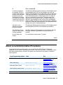
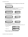
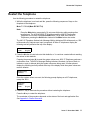
1. Press the # button to accept the ID shown or enter a new 802.1X ID for the telephone using
up to 12 ASCII characters. Press # after entry of a new ID.
2. The IP Telephones display the following 802.1X password entry screen:
Password=_
#=OK
Issue 5 November 2006
37
4600 Series IP Telephone Installation
3. Enter the 802.1X password using up to 12 numeric characters and press #.
Note:
Note:
For security purposes, an asterisk displays in place of each digit entered.
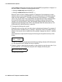
4. The telephone displays the following:
Waiting for 802.1X
authentication...
5. If authentication is successful, the telephone stores a new ID and password in
reprogrammable non-volatile memory, and starts the DHCP process. If unsuccessful, the
telephone displays a failure message and repeats the authentication process from Step 1.
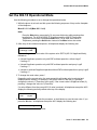
DHCP Processing
The IP telephone sends a request to the DHCP server and invokes the DHCP process.
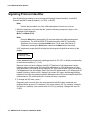
1. The telephone displays one of the following messages:
DHCP: s secs
# to program
DHCP: s secs
VLAN ID = n
DHCP: s secs
where s is the number of seconds that have elapsed since DHCP was invoked. The
message on the left appears if 802.1Q tagging is off and access to local programming
procedures is not disabled or restricted. (See Chapter 3: Local Administrative Options for
specifics.) The middle message appears if 802.1Q tagging is on and access to local
programming procedures is disabled or restricted. If the left and middle messages alternate
every two seconds, 802.1Q tagging is on. When both messages alternate, access to local
programming procedures is not disabled or restricted. Finally, the message on the right
appears if 802.1Q tagging is off and access to local programming procedures is disabled or
restricted.
2. The DHCP server provides IP Addresses for the following hardware:
●
The IP telephone
●
The TFTP or HTTP server
●
The TN799B, C, or D Control-LAN (C-LAN) circuit pack on the media server (for IP
telephones supporting H.323 protocol)
The 4601 and 4601+ cannot display messages. Therefore, if the DHCP process locates the
required information, the 4601’s Call Appearance Line b indicator flashes continuously 500
milliseconds on, 500 milliseconds off while all other LEDs remain lit. If the appropriate
information cannot be discerned or is missing, the 4601’s Call Appearance Line a indicator
flutters 50 milliseconds on, 50 milliseconds off three times while all other LEDs remain lit,
and a reset occurs.
38 4600 Series IP Telephone Installation Guide
Dynamic Addressing Process
3. Using the list of gateway IP Addresses provided by the DHCP server, the telephone
performs a router check. The telephone cycles through the gateway IP Addresses with
ARPs or pings until it receives a response. During this search, the 4601’s Call Appearance
Line b indicator flashes continuously 500 milliseconds on, 500 milliseconds off. All other
4601 LEDs remain lit.
When the router is located, the TFTP or HTTP process starts. If no router is found for a
4601/4601+ IP Telephone, its Call Appearance Line b flutters 50 milliseconds on, 50
milliseconds off three times. All other 4601 LEDs remain lit, and a reset occurs.
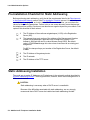
TFTP/HTTP Processing
The IP telephone connects to the TFTP or HTTP/HTTPS server and looks for an upgrade script
file.
During TFTP or HTTP processing for the 4601/4601+ IP Telephone, both Call Appearance
Line indicators flash continuously 500 milliseconds on, 500 milliseconds off while all other
LEDs remain lit. If the appropriate information cannot be discerned or is missing, both of the
4601’s Call Appearance Line indicators flutter 50 milliseconds on, 50 milliseconds off three
times. All other 4601/4601+ LEDs remain lit, and a reset occurs.
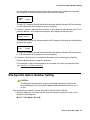
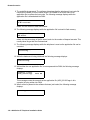
1. The TFTP or HTTP server sends and identifies an upgrade script.
The read request packet might have to be sent several times. Each time the RRQ message
is sent, all IP telephones except the 4601/4601+ display one of the following messages:
TFTP: #
www.xxx.yyy.zzz
HTTP: n uri
For TFTP, # is the number of TFTP requests made by the telephone and www.xxx.yyy.zzz
is the IP Address of the current TFTP request. For HTTP, n is the number of HTTP requests
made by the telephone and uri is the URI for the current HTTP request.
2. While the upgrade script file is being downloaded, all IP telephones except the 4601/4601+
display the following message:
46xxUPGRADE.SCR
n KB received
where n is the number of KBs received from the TFTP server.
Issue 5 November 2006
39
4600 Series IP Telephone Installation
3. While the application file is downloaded to the IP telephone, all IP telephones except the
4601/4601+ display the following message:
filename
n KB received
where n is the number of KBs received from the TFTP server. Then the telephone
downloads the 46xxsettings.txt file.
4. While the application file is saved in flash memory, all IP telephones except the 4601/4601+
display the following message:
Saving to flash
1%, 1 secs
with the percentage of the file and the number of elapsed seconds incremented as the
application file is stored in flash memory.
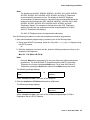
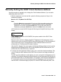
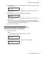
Media Server Registration
The telephone contacts the Avaya Media Server and attempts to log in.
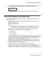
All IP telephones except the 4601 display the following prompt for an extension:
Extension=nnnnnn
#=OK NEW=_
The 4601/4601+ IP Telephone indicates the server is waiting for an extension entry by
flashing the Message Waiting Indicators 500 milliseconds on, 500 milliseconds off. The
Message Waiting indicators are located at the top of the telephone and the Message button
LED on the left middle of the faceplate.
1. Enter a new extension, ending with the # button. All telephones except the 4601/4601+
display each digit entered, while the 4601/4601+ provides LED and button-click feedback.
To register the telephone without the extension or password (unnamed), press only the #
button or make no entry and wait 60 seconds.
Note:
Note:
Unnamed registration is the capability to register a telephone with the call server
without entry of an extension or password. Telephones registered unnamed have
limited functionality. For more information, see Unnamed Registration on
page 45.
All IP telephones except the 4601/4601+ display the following prompt for a password:
Password=_
#=OK
40 4600 Series IP Telephone Installation Guide
Downgrading Avaya IP Telephones (H.323 Only)
2. Enter the password, ending with the # button. The 4601/4601+ provides LED and
button-click feedback for each digit upon entry. To register the telephone without the
extension or password (unnamed), press only the # button or make no entry and wait 60
seconds.
Except for the 4601 and 4601+, the extension is visible as you enter it but the password
displays as asterisks. The 4601/4601+ just provides LED and button-click feedback for
password entry.
3. If entered, the system determines whether the extension is in use and if the password is
valid.
4. Successful completion of this process produces the dial tone.
The IP telephone was installed successfully.
Downgrading Avaya IP Telephones (H.323 Only)
!
Important:
Important:
We strongly recommend that you upgrade DEFINITY to the latest release rather
than take the extreme steps in this section. There is no reason currently known to
downgrade any Avaya IP Telephone except to install a 4612 or 4624 IP
Telephone on a DEFINITY switch with a release prior to R9.5.
! CAUTION:
CAUTION:
Never attempt to downgrade an Avaya 4630 IP Telephone with a release earlier
than R1.8.
Create a TFTP server. Provide it with an IP Address (IP_tftp) on the same sub-net as the IP
telephones you want to downgrade. Then:
1. Install the R1.1 software for DEFINITY Release 9 or R1.0 for DEFINITY Release 8.4 on the
TFTP server.
2. Manually assign the IP Addresses for each 4612 or 4624, as indicated in Static Addressing
Installation on page 54 - including the FileSvr (IP_tftp).
3. Reboot the 4612 or 4624. The telephone downloads and installs the old boot code. This
results in the manual addresses of the IP telephones being erased.
4. Manually assign the IP Addresses for each 4612 or 4624 including the FileSvr (IP_tftp).
5. Reboot the 4612 or 4624. The telephone will download and install the R1.1 or R1.0 release.
6. Manually assign the IP Addresses to each 4612 or 4624. Assign 0.0.0.0 for the FileSvr. This
will prevent the telephones from upgrading until you are ready for them to upgrade.
7. Remove the old software from the TFTP server. Removing the old software prevents some
other Avaya IP Telephone from inappropriately downgrading.
Issue 5 November 2006
41
4600 Series IP Telephone Installation
Converting Software on Avaya 4600 Series IP Telephones
The 4602SW+, 4610SW, 4620SW, and 4621SW IP Telephones use either H.323 or SIP
software. These telephones come from the factory with H.323 software loaded by default. This
section describes how to convert from H.323 to SIP software, or from SIP to H.323 software.
There are several H.323 to SIP or SIP to H.323 conversion scenarios, and each scenario
depends on whether the majority of your telephones are H.323 or SIP:
●
H.323-Centric - an environment where the majority of IP telephones are and will remain
running H.323 software, but some telephones will become SIP IP telephones. In an
H.323-centric environment, the 46xxH323... software bundle must reside on the HTTP
server and Communication Manager must be configured with the appropriate H.323
parameters. To convert an individual telephone from H.323 to SIP, both the SIP
Enablement Services (SES) server and Avaya Communication Manager (CM) must be
configured with the appropriate SIP parameters. Any telephone in use prior to conversion
must run Release 2.0 or greater software with a SIG parameter value of “default” (H.323).
See Table 1, the H.323 to SIP and SIP to H.323 Conversion Chart for conversion
instructions.
●
SIP-Centric - an environment where the majority of IP telephones are or will become SIP
telephones running SIP software. In a SIP-centric environment, the 46xxSIP... software
bundle must reside on the HTTP server and both SES and CM must be configured with the
appropriate SIP parameters. To convert an individual telephone from SIP to H.323, Avaya
Communication Manager (CM) must be configured with the appropriate H.323
parameters. Any telephone in use prior to conversion must run Release 2.0 or greater
software with a SIG parameter value of “default” (SIP). See Table 1, the H.323 to SIP and
SIP to H.323 Conversion Chart for conversion instructions.
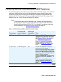
What makes an environment H.323 or SIP depends on the type of upgrade script files the
environment is running (H.323 or SIP) and the Signaling Protocol Identifier (SIG) parameter
setting. The SIG parameter has three possible values:
●
Default - either H.323 or SIP, set automatically for all telephones depending on the nature
of files downloaded to the SES server or Communication Manager.
●
H.323 - manually set to H.323 for a specific telephone by an installer or administrator
according to the procedures in this section.
●
SIP - manually set to SIP for a specific telephone by an installer or administrator according
to the procedures in this section.
42 4600 Series IP Telephone Installation Guide
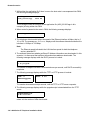
Converting Software on Avaya 4600 Series IP Telephones
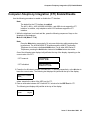
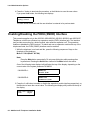
Converting 4602+/4610SW/4620SW/4621SW IP Telephones
An H.323 IP telephone can be either in use with possible customized settings or out of the box
with factory default settings. An out of the box telephone requires accessing the manual
programming mode early in the process and setting the Signaling Protocol Identifier (SIG)
parameter to “SIP.” Converting to SIP early avoids having to first load H.323 software, log in,
and then invoke the “in use” process to load the SIP software.
Note:
Note:
For information about the SIG parameter, see “Choosing the Right Application
File and Upgrade Script File” in the 4600 Series IP Telephone LAN Administrator
Guide (Document Number 555-233-507). For information on setting or changing
the SIG parameter, see Signaling Protocol Identifier on page 78.
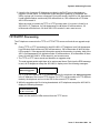
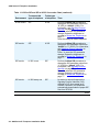
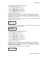
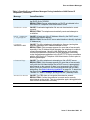
Table 1: H.323 to SIP and SIP to H.323 Conversion Chart
Environment
To convert this
type of telephone
To this type
of telephone
H.323-centric
H.323 in use
SIP
Perform the Mute SIG procedure to
change the SIG parameter value from
“default” to “2" (SIP).” For information,
see Signaling Protocol Identifier on
page 78.
Press * to save the SIG parameter
change. Restart the telephone as
covered in Restart the Telephone on
page 77.
H.323-centric
H.323 factory set
SIP
Connect the telephone to a power
source and to the network.
As soon as you see the DHCP prompt,
press * to enter manual programming
mode. Press # multiple times to accept
the existing values until the telephone
displays “Enter command.”.
Perform the Mute SIG procedure and
change the value from “default” to “2"
(SIP).
Press * to save the SIG parameter
change. Restart the telephone as
covered in Restart the Telephone on
page 77.
Then:
1 of 2
Issue 5 November 2006
43
4600 Series IP Telephone Installation
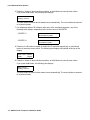
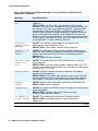
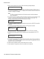
Table 1: H.323 to SIP and SIP to H.323 Conversion Chart (continued)
Environment
To convert this
type of telephone
To this type
of telephone
H.323-centric
SIP
H.323
Perform the Mute SIG procedure to
change the SIG parameter value from
“2" (SIP) to “default” (H323). For
information, see Signaling Protocol
Identifier on page 78.
Press * to save the SIG parameter
change. Restart the telephone as
covered in Restart the Telephone on
page 77.
Save the change & restart telephone.
SIP-centric
SIP
H.323
Perform the Mute SIG procedure to
change the SIG parameter value from
“default” to “1" (H323). For information,
see Signaling Protocol Identifier on
page 78.
Press * to save the SIG parameter
change. Restart the telephone as
covered in Restart the Telephone on
page 77.
SIP-centric
H.323 in use
SIP
Perform the Mute SIG procedure to
change the SIG parameter value from
“1" (H323) to “default” (SIP). For
information, see Signaling Protocol
Identifier on page 78.
Press * to save the SIG parameter
change. Restart the telephone as
covered in Restart the Telephone on
page 77.
SIP-centric
H.323 factory set
SIP
No action is required because the
Signaling Protocol Identifier (SIG)
defaults to SIP. Upon power-up &
network connection, the telephone
automatically downloads the proper SIP
files from SES/CM.
Then:
2 of 2
44 4600 Series IP Telephone Installation Guide
Unnamed Registration
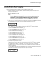
Unnamed Registration
As of Release 2.4, 4600 Series IP Telephones support unnamed registration. A telephone can
register with the call server and receive limited service without requiring an extension and
password entry. Unless otherwise disabled, the telephone automatically attempts to register
unnamed if no action is taken on the Extension entry screen.
A telephone registered without the extension and password has the following characteristics:
●
only one call appearance, preventing conferences or call transfers,
●
no administrable feature buttons,
●
on-hook dialing cannot be invoked,
●
limited to the calling capability administered for PSA (Personal Station Access) on the call
server, for example, only outgoing calls permitted subject to call server Class of
Restriction/Class of Service limitations, and
●
can be converted to normal, named registration by a valid extension and password entry.
The telephone can be administered to avoid unnamed registration and remain unregistered if no
extension and password are provided. For more information, see the 4600 Series IP Telephone
LAN Administrator Guide.
802.1X Supplicant Operation
If your environment uses the IEEE 802.1X standard, consult the LAN Administrator before you
install any of these 4600 Series IP Telephone models:
●
4602SW+
●
4610SW
●
4620SW
●
4621SW
●
4622SW
●
4625SW
802.1X operation can differ for each network. Consulting with the LAN Administrator helps
determine the best way to install IP telephones to operate under this standard.
Issue 5 November 2006
45
4600 Series IP Telephone Installation
In general, each telephone must have an 802.1X ID and password so that the network access
process is successful. When operating under 802.1X, Avaya suggests that you:
●
pre-stage installation in a lab or on a small non-802.1X network, avoiding 802.1X
authentication until after the telephone receives an application software download,
●
connect the telephones with upgraded software to the network under which they will
normally operate, and
●
perform the Set the 802.1X Operational Mode procedure for each telephone to assign an
802.1X operational mode.
Your Avaya technical consultant can assist you in optimizing 4600 Series IP Telephone
installation in an 802.1X environment.
46 4600 Series IP Telephone Installation Guide
Chapter 3: Local Administrative Options
Introduction
After you have successfully installed an IP telephone, you might be instructed to administer one
of the options described in this chapter.
Note:
Note:
You can modify the settings file to set parameters for IP telephones that
download their upgrade script and application files from the same TFTP or HTTP
server. See the section on “4600 Series IP Telephone Scripts and Application
Files” in Chapter 4 of the 4600 Series IP Telephone LAN Administrator Guide.
Because the 4601 and 4601+ IP Telephones do not have a display, they are
limited in their ability to support Local Administrative Procedures. Specifically, the
only Local Administrative Procedures the 4601/4601+ supports are:
- RESET (and Restart)
- SIG
- SSON
- TEST
- CHADDR (DHCP Client Hardware Address)
- ALERT
- TAG
- LOG
- LOGOFF
- AGC (for handset only)
In addition, because it lacks a display to provide visual feedback during data entry, the
4601 IP Telephone has unique data entry and feedback procedures. See Entering Data
for the 4601 IP Telephone on page 50.
Issue 5 November 2006
47
Local Administrative Options
! CAUTION:
CAUTION:
Perform these procedures only if instructed to do so by the system or LAN
administrator.
Static administration of these options causes upgrades to work differently than if
they are administered dynamically. Values assigned to options in static
administration are not changed by upgrade scripts. These values remain active
for the telephone until either:
- a new boot file is downloaded, or
- the IP telephone is reset, as indicated in Reset System Values on page 75.
Aside from SSON, use these option-setting procedures only with static addressing
and, as always, only if instructed by the system or LAN administrator. Aside from
SSON, do not use these option-setting procedures if you are using DHCP. DHCP is
the Dynamic Addressing Process, as indicated in Dynamic Addressing Process on
page 36.
Entering Data for Administrative Options
This section applies to all IP telephones with a display. It does not apply to the 4601 IP
Telephone, which does not have a display. This section describes how to enter data for
administrative options.
1. Invoke all local procedures by pressing the Hold or Mute button, up to 7 numeric dial pad
buttons, and the # button. The 4630/4630SW IP Telephones and the 4690 IP Conference
Telephone do not have a dedicated Hold button. On these phones, you must use the Mute
button to access these options.
A 6-second timeout is in effect between button presses after pressing the Hold button. If
you do not press a valid button within 6 seconds of pressing the previous button, the
collected digits are discarded. In this case, no administrative option is invoked.
2. Attempts to enter invalid data are rejected, and the telephone emits an error beep.
3. If you enter a numeric digit for a value or for an IP Address or subnet mask field after
entering only a zero, the new digit replaces the zero.
4. Press the # button to go to the next step.
48 4600 Series IP Telephone Installation Guide
Entering Data for Administrative Options
5. How to backspace depends on the type of telephone being installed, as shown in this chart:
IP Telephone #
Backspace Alternative
4601
Call Appearance a button
4601+
Call Appearance a button
4602
Speaker button
4602SW
Speaker button
4602SW+
Speaker button
4606
Conference button
4610SW
Left-most softkey
4612
Left-most softkey or Previous button
4620
Left-most softkey
4620SW
Left-most softkey
4621SW
Left-most softkey
4622SW
Left-most softkey
4624
Left-most softkey or Previous button
4625SW
Left-most softkey
4630
Headset button
4630SW
Headset button
4690
Left-most softkey
When you press the applicable button or key to backspace, the most recently entered digit
or period is erased from the display. The cursor remains in the erased character’s former
position.
6. If PROCPSWD is administered as indicated in Chapter 4 of the 4600 Series IP Telephone
LAN Administrator Guide, you must type the Local Procedure password after pressing
Mute and before pressing the code for your given local programming option.
Note:
Note:
If PROCSTAT has been administered to 1, as described in Chapter 4 of the 4600
Series IP Telephones LAN Administrator Guide, you will not be able to invoke any
administrative options other than V I E W.
Issue 5 November 2006
49
Local Administrative Options
Entering Data for the 4601 IP Telephone
Because the 4601 IP Telephone has no display, its LEDs indicate:
Note:
●
when data entry is required,
●
whether processing is taking place, prohibiting data entry, and
●
confirmation that a process or procedure is complete.
Note:
This procedure also applies to the 4601+ IP Telephone.
1. Invoke all local procedures by pressing the Hold button, up to 7 numeric dial pad buttons,
and the # button.
A 6-second timeout is in effect between button presses after pressing the Hold button. If
you do not press a valid button within 6 seconds of pressing the previous button, the
collected digits are discarded. In this case, no administrative option is invoked.
2. Attempts to enter invalid data are rejected, and the telephone emits an error beep.
3. Press the # button to go to the next step.
4. To backspace within a field, press Call Appearance a’s Line button.
5. The following chart provides specific 4601 data entry/telephone interaction information.
If
Then
User input is expected/
required
The Message Waiting indicator at the top of the telephone and
the Message button LED on the faceplate flash 500
milliseconds on, 500 milliseconds off.
The telephone is
providing feedback
after an entry of one or
more numeric digits
from 1 to 9
Call Appearance Line a’s indicator winks 200 milliseconds on,
50 milliseconds off n times for digit n. For example, if you
press 2 as the first digit of a value like the SSON, Call
Appearance Line a’s indicator winks two times.
For values having more than one digit with a second numeric
digit from 1 to 9, Call Appearance Line b’s indicator winks 200
milliseconds on, 50 milliseconds off n times for digit n. For
example, if you press 4 as the SSON’s second digit, Call
Appearance Line b’s indicator then winks four times.
Each subsequent digit of a specific value causes Call
Appearance Lines a and b to alternate winks.
The telephone is
providing feedback
after an entry of
0 (zero)
Pressing 0 (zero) for a value causes the appropriate Call
Appearance Line indicator to flutter five times, 50 milliseconds
on, 50 milliseconds off.
1 of 2
50 4600 Series IP Telephone Installation Guide
About Local Administrative Procedures
If
Then (continued)
In certain procedures,
for example, SSON or
to display the extension
number, a value already
exists and you press
the # button to indicate
you either want to enter
a new value or have the
current value displayed
The Message Waiting indicator at the top of the telephone and
the Message button’s LED on the faceplate are lit but not
flashing. Call Appearance Line a alternating with line b after an
1800 millisecond pause, if the value has more than one digit
winks 600 milliseconds on, 200 milliseconds off n times for
digit n to indicate the current value. The appropriate Call
Appearance Line indicator flutters five times to indicate the
digit zero. After feedback of the current value, the Message
Waiting indicator at the top of the telephone and the Message
button’s LED flash 500 milliseconds on, 500 milliseconds off to
indicate user input is expected/required.
User input is not
allowed for example,
during processing
The Message Waiting indicator at the top of the telephone and
the Message button LED on the faceplate are steadily lit.
The telephone’s boot
image is in the process
of being upgraded
All LEDs, meaning Call Appearance Lines a and b, and both
Message indicators, light steadily during the download
process.
An error beep tone
sounds
An invalid button was pressed. Try again.
2 of 2
About Local Administrative Procedures
Local administrative procedures allow you to customize the 4600 Series IP Telephone
installation for your specific operating environment. This section provides a description of each
local administrative option covered in this guide, with references to the pages on which the
option appears.
Local Programming Option
Code
See
802.1X
8 0 2 1 9 (8 0 2 1 X)
Set the 802.1X
Operational Mode on
page 53.
Static addressing
A D D R (2 3 3 7)
Static Addressing
Installation on page 54.
Automatic Gain Control
A G C (2 4 2)
Disable/Enable Automatic
Gain Control on page 58.
Visual Alerting mode control
A L E R T (2 5 3 7 8)
Visual/Audible Alerting
Procedure on page 59.
1 of 2
Issue 5 November 2006
51
Local Administrative Options
Local Programming Option
Code
See
DHCP chaddr field value
C H A D D R (2 4 2 3 3 7)
Manually Setting the
DHCP Client Hardware
Address on page 61.
Clear values to factory
defaults
C L E A R (2 5 3 2 7)
Clear Procedure on
page 62.
Contrast Control
C O N T (2 6 6 8)
Adjusting the Contrast
Control on page 64.
Computer-Telephony
Integration
C T I (2 8 4)
Computer-Telephony
Integration (CTI) Enable/
Disable on page 65.
FKEU (XMOD) Enable/
Disable
F K E U (3 5 3 8 #)
Enabling/Disabling the
FKEU (XMOD)
Interface on page 66
Group Identifier
(Release 2.0 and later only)
G R O U P (4 7 6 8 7)
Group Identifier on
page 67.
PC Ethernet Interface
I N T (4 6 8)
Interface Control on
page 68.
Event Logging
L O G (5 6 4)
Disable/Enable Event
Logging on page 71.
Log off the telephone
L O G O F F (5 6 4 6 3 3)
Logoff on page 72.
Turn Display Backlight Off
O F F (6 3 3)
Turning Off the
Backlight on page 73.
Quality of Service options
Q O S (7 6 7)
QoS Option Setting on
page 73.
Reset the telephone
R E S E T (7 3 7 3 8)
Reset System Values on
page 75.
Restart the telephone
R E S E T (7 3 7 3 8)
Restart the Telephone on
page 77.
Signaling protocol identifier
(Release 2.0 and later only)
S I G (7 4 4)
Signaling Protocol
Identifier on page 78.
Site-Specific Option Number
S S O N (7 7 6 6)
Site-Specific Option
Number Setting on
page 79.
Layer 2 frame tagging control
(4601/4601+ only)
T A G (8 2 4)
Setting L2Q Tagging
Control (4601 Only) on
page 81.
Test the telephone
T E S T (8 3 7 8)
Self-Test Procedure on
page 82.
View System Parameter
Values
V I E W (8 4 3 9)
The View Administrative
Option on page 87.
2 of 2
52 4600 Series IP Telephone Installation Guide
Set the 802.1X Operational Mode
Set the 802.1X Operational Mode
Use the following procedure to set or change the operational mode.
1. While the phone is on-hook and idle, press the following sequence of keys on the faceplate
of the telephone:
Mute 8 0 2 1 9 # (Mute 8 0 2 1 x #)
Note:
Note:
Press the Mute button momentarily. Do not press this button while pressing other
keys/buttons. The 4630/4630SW IP Telephones and the 4690 IP Conference
Telephone do not have a dedicated Hold button. For all other 4600 Series IP
Telephones, pressing the Hold button instead of the Mute button also works.
2. After entry of the command sequence, all telephones display the following text:
802.1X=setting
*=change #=OK
where setting is the current value of the system value DOTIX (802.1X Supplicant Mode),
defined as:
●
Unicast Supplicant operation only with PAE multicast pass-thru, without Logoff
if setting = 0
●
Unicast Supplicant operation only with PAE multicast pass-thru and proxy Logoff
if setting = 1
●
Unicast or multicast Supplicant operation without PAE multicast pass-thru or proxy Logoff
if setting = 2
3. To change the mode value, press *.
Depending on the current value, the next sequential valid mode value is selected and
displayed as the setting. For example, if the current value is Pass-thru (0), pressing *
changes the value to 1 (Pass-thru with Logoff). If the current value is Supplicant mode (2),
pressing * changes the value to 0 (Pass-thru).
If a value different from the current 802.1X value is entered, all telephones except the 4601
display the following text left-justified at the top of the display:
Save new value?
*=no
#=yes
4. Press the * button to terminate the procedure, or the # button to save the new value. If you
press the # button, all telephones except the 4601 display the following text:
New value being saved
The telephone saves the new value.
Issue 5 November 2006
53
Local Administrative Options
Pre-Installation Checklist for Static Addressing
Before performing static addressing, verify that all the requirements listed in the Requirements
to Verify about the Network section of the Pre-Installation Checklist are met. You do not have to
consider item 4. on page 20, as it refers to the DHCP server. In addition, you must have the
values for the following parameters. Failure to do so can cause data entry errors that prevent
the telephone from working. Such errors can also have a negative impact on your network. Print
copies of this checklist for each subnet.
1.
The IP Address of the media server/gatekeeper (H.323) or the Registration
Server (SIP).
2.
The transport layer port number of the address of the Management Complex
(media server/gatekeeper, applicable only to telephones running H.323
software). Although this can be a value between 0 and 65535, the default
value is 1719. Do not change this value unless it conflicts with an existing port
assignment.
For SIP, the transport layer port number of the Registration Server; the default
is 5060.
3.
The IP Address of the gateway/router.
4.
The IP netmask.
5.
The IP Address of the TFTP server.
Static Addressing Installation
The usual way to assign IP Addresses to IP telephones is the automatic method described in
Dynamic Addressing Process. There might be times, however, when manual assignment of IP
Addresses is desired.
! CAUTION:
CAUTION:
Static addressing is necessary when a DHCP server is unavailable.
Because of the difficulties associated with static addressing, we very strongly
recommend that a DHCP server be installed and static addressing avoided.
54 4600 Series IP Telephone Installation Guide
Static Addressing Installation
Note:
Note:
The displays on the 4602, 4602SW, 4602SW+, 4610SW, 4612, 4620, 4620SW,
4621SW, 4622SW, 4624, 4625SW, 4630, 4630SW, and 4690 IP Telephones
accommodate 24 characters per line. The display on the 4606 Telephone
accommodates 16 characters per line. Here and in the procedures that follow, the
example on the left shows the 4602, 4602SW, 4602SW+, 4610SW, 4612, 4620,
4620SW, 4621SW, 4622SW, 4624, 4625SW, 4630, 4630SW, and 4690
Telephones’ display. The example on the right shows the 4606 Telephone’s
display. Showing only one example means that example applies to all 4600
Series IP Telephones with displays.
The 4601 IP Telephone does not support static addressing.
Use the following procedure to invoke manual address information programming.
1. Start manual address programming by performing one of the following steps:
a. During normal DHCP processing, press the * key while “* to program“ displays during
the DHCP process.
or
b. While the telephone is on-hook and idle, press the following sequence of keys on the
faceplate of the telephone:
Mute 2 3 3 7 # (Mute A D D R #)
Note:
Note:
Press the Mute button momentarily. Do not press this button while pressing other
keys/buttons. The 4630/4630SW IP Telephones and the 4690 IP Conference
Telephone do not have a dedicated Hold button. For all other 4600 Series IP
Telephones, pressing the Hold button instead of the Mute button also works.
The following message displays:
Phone=nnn.nnn.nnn.nnn
New=_
or
nnn.nnn.nnn.nnn
Phone=_
where nnn.nnn.nnn.nnn is the value of the telephone.
2. Enter the telephone’s IP Address followed by the # button.
The following message displays:
CallSv=nnn.nnn.nnn.nnn
New=_
or
nnn.nnn.nnn.nnn
CallSv=_
where nnn.nnn.nnn.nnn is the value of the media server/gatekeeper (H.323) or
Registration Server (SIP) IP Address.
Issue 5 November 2006
55
Local Administrative Options
3. Enter the Gatekeeper IP Address (H.323) or Registration Server IP Address (SIP)
followed by the # button.
The following message displays:
CallSvPort=nnnnn
New=_
where nnnnn is the value of the Management Complex (media server/gatekeeper)
transport-layer port number, a value between 0 and 65535.
4. Enter the appropriate value for the Port Number followed by the # button.
The following message displays:
or
Router=nnn.nnn.nnn.nnn
New=_
nnn.nnn.nnn.nnn
Router=_
where nnn.nnn.nnn.nnn is the value of the gateway/router IP Address.
5. Enter the Gateway router IP Address followed by the # button.
The following message displays:
or
Mask=nnn.nnn.nnn.nnn
New=_
nnn.nnn.nnn.nnn
Mask=_
where nnn.nnn.nnn.nnn is the value of the IP netmask.
6. Enter the IP netmask followed by the # button.
The following message displays:
or
FileSv=nnn.nnn.nnn.nnn
New=_
nnn.nnn.nnn.nnn
FileSv=_
where nnn.nnn.nnn.nnn is the value of the TFTP server IP Address.
7. Enter the TFTP/HTTP Server IP Address followed by the # button.
One of the following texts displays left-justified at the top of the display, depending on the
current status of 802.1Q:
If 802.1Q is off:
802.1Q=off
1=on #=OK
If 802.1Q is on:
802.1Q=on
0=off #=OK
8. Press the 1 or 0 button to turn 802.1Q on or off respectively.
The display is updated to show the current status of 802.1Q.
56 4600 Series IP Telephone Installation Guide
Static Addressing Installation
9. Press the # button to continue the procedure without changing the displayed status of
802.1Q
The following text displays left-justified at the top of the display:
VLAN ID=dddd
New=_
where dddd is the value of the 802.1 VLAN ID.
10. Enter a valid value between 0 and 4094 for the new value of the 802.1 VLAN ID.
The following message displays:
VLAN test=ddd
New=_
where ddd is the value of the DHCPOFFER wait period.
11. Enter a valid value between 0 and 999 for the new value of the DHCPOFFER wait period.
The following message displays:
Save new
values?
*=no #=yes
12. Press the # button to save the new values you entered.
The following message displays:
New values
being saved
Once the new values are stored, the telephone is reset.
If a new boot program is downloaded from the TFTP server after you enter static addressing
information, you must reenter your static addressing information.
Issue 5 November 2006
57
Local Administrative Options
Disable/Enable Automatic Gain Control
Use the following procedure to turn automatic gain control for the handset, headset, and/or the
Speaker on or off.
1. While the telephone is on-hook and idle, press the following sequence of keys on the
faceplate of the telephone:
Mute 2 4 2 # (Mute A G C #)
Note:
Note:
Press the Mute button momentarily. Do not press this button while pressing other
keys/buttons. The 4630/4630SW IP Telephones and the 4690 IP Conference
Telephone do not have a dedicated Hold button. For all other 4600 Series IP
Telephones, pressing the Hold button instead of the Mute button also works.
2. After entry of the command sequence, all telephones except the 4601 display the following,
based on the current value of the system value AGCHAND:
If AGCHAND = 1:
Handset AGC=on
0=off #=OK
If AGCHAND = 0:
Handset AGC=off
1=on #=OK
3. To change the AGC Handset value from On to Off, press 0. To change the AGC Handset
value from Off to On, press 1.
If the telephone has a Headset interface one of the following displays, based on the current
value of the system value AGCHEAD:
If AGCHEAD = 1:
Headset AGC=on
0=off #=OK
If AGCHEAD = 0:
Headset AGC=off
1=on #=OK
If the telephone does not have a headset interface, proceed to Step 5.
4. To change the AGC Headset value from On to Off, press 0. To change the AGC Headset
value from Off to On, press 1.
One of the following displays, based on the current value of the system value AGCSPKR:
If AGCSPKR = 1:
Speaker AGC=on
0=off #=OK
If AGCSPKR = 0:
Speaker AGC=off
1=on #=OK
58 4600 Series IP Telephone Installation Guide
Visual/Audible Alerting Procedure
5. To change the AGC Speaker value from On to Off, press 0. To change the AGC Speaker
value from Off to On, press 1.
If a value different from the current AGCHAND value and/or the current AGCHEAD value
and/or the current AGCSPKR value is entered, all telephones except the 4601 display the
following text left-justified at the top of the display:
Save new value?
*=no
#=yes
6. Press the * button to terminate the procedure, or the # button to save the new value(s). If
you press the # button, all telephones except the 4601 display the following text:
New value being saved
The telephone saves the new value(s).
Visual/Audible Alerting Procedure
Use this procedure to set or change the Alerting mode. As of software Release 2.2, all 4600
Series IP Telephones can alert a user to incoming calls audibly (the default) or both audibly and
visually. Visual alert is useful in noisy environments where an audible alert might not be heard,
or to tell at a glance which of several phones is ringing.
1. While the telephone is on-hook and idle, press the following sequence of keys on the
telephone’s faceplate:
Mute 2 5 3 7 8 # (Mute A L E R T #)
Note:
Note:
Press the Mute button momentarily. Do not press this button while pressing other
keys/buttons. The 4630/4630SW IP Telephones and the 4690 IP Conference
Telephone do not have a dedicated Hold button. For all other 4600 Series IP
Telephones, pressing the Hold button instead of the Mute button also works.
All IP telephones except the 4601 display the following text left-justified at the top of the
display:
Alerting=setting
*=change #=OK
Issue 5 November 2006
59
Local Administrative Options
where setting corresponds the current Alert value (NVALERT) as specified in “Chapter 4" of
the 4600 Series IP Telephone LAN Administrator Guide:
●
Setting is audible-only when NVALERT = 0
●
Setting is audible/visual when NVALERT = 1
Because it does not have a display, the 4601 IP Telephone’s Call Appearance Line a’s
indicator winks out the current NVALERT value 600 milliseconds on, 200 milliseconds off,
where one wink represents “0” for audible only and two winks represent “1” for audible/
visual. If the current value is zero (the default), Call Appearance Line a’s indicator flutters
five times 50 milliseconds on, 50 milliseconds off instead of winking. After the 4601
“displays” the current NVALERT value, the Message Waiting indicator at the top of the
telephone and the Message button LED on the faceplate flash 500 milliseconds on, 500
milliseconds off to indicate an entry is expected.
2. To change the Alerting value, press *.
Depending on the current value, the other value is selected and displayed. For example, if
the current value is audible/visual (1), pressing * changes the value to 0 (audible only, the
default). If the current value is audible-only (0), pressing * changes the value to 1 (audible/
visual).
All IP telephones except the 4601 display the following text left-justified at the top of the
display:
Save new value?
*=no
#=yes
The 4601 IP Telephone instead flashes both Message Waiting indicators 500 milliseconds
on, 500 milliseconds off to indicate an entry is expected.
3. Press the * button to terminate the procedure, or the # button to save the new value. If you
press the # button, all IP telephones except the 4601 display the following text:
New value being saved
The new value is saved.
60 4600 Series IP Telephone Installation Guide
Manually Setting the DHCP Client Hardware Address
Manually Setting the DHCP Client Hardware Address
Use this procedure to manually set or change the Client Hardware Address, if you use static
addressing rather than DHCP.
1. While the telephone is on-hook and idle, press the following sequence of keys on the
telephone’s faceplate:
Mute 2 4 2 3 3 7 # (Mute C H A D D R #)
Note:
Note:
Press the Mute button momentarily. Do not press this button while pressing other
keys/buttons. The 4630/4630SW IP Telephones and the 4690 IP Conference
Telephone do not have a dedicated Hold button. For all other 4600 Series IP
Telephones, pressing the Hold button instead of the Mute button also works.
All IP telephones except the 4601 display the following text left-justified at the top of the
display:
chaddr=dddddd
New=
where dddddd is the value of NVCHADDR, the system variable for the DHCP Client
Hardware Address.
Because it does not have a display, the 4601 IP Telephone’s Call Appearance Line a’s
indicator winks out the current NVCHADDR value 600 milliseconds on, 200 milliseconds off.
If the current value is zero, Call Appearance Line a’s indicator flutters five times 50
milliseconds on, 50 milliseconds off instead of winking.
After the 4601 “displays” the current value, the Message Waiting indicator at the top of the
telephone and the Message button LED on the faceplate flash 500 milliseconds on, 500
milliseconds off to indicate an entry is expected.
2. To change the Client Hardware Address value, enter a valid client hardware address. This
value is usually the MAC address, which DHCP then converts to an integer preceded by
zeroes.
The 4601 provides feedback for each digit as you enter it using both Call Appearance Line
indicators. The indicators alternate winking the number of times represented by the digit you
press 200 milliseconds on, 50 milliseconds off. For example, if the first digit of the address is
“2,” pressing the number 2 on the dial pad causes Call Appearance Line a’s indicator to
wink two times. If the second digit you press is “4,” after an 1800 millisecond pause, Call
Issue 5 November 2006
61
Local Administrative Options
Appearance Line b’s indicator winks four times. Pressing “0” (zero) on the dial pad causes
the appropriate indicator to flutter three five 50 milliseconds on, 50 milliseconds off.
Then the 4601 flashes both Message Waiting indicators 500 milliseconds on, 500
milliseconds off to indicate an entry is expected.
For all IP telephones except the 4601, if a value different from the current value of
NVCHADDR is entered, the following text displays left-justified at the top of the display:
Save new value?
*=no
#=yes
3. Press the * button to terminate the procedure, or the # button to save the new value. If you
press the # button, all IP telephones except the 4601 display the following text:
New value being saved
All phones save the new value.
Clear Procedure
Sometimes, you might want to remove all administered values, user-specified data, and option
settings. Essentially, you want to return a telephone to its initial “clean slate” condition.
This is usually done when passing a telephone to a new, dedicated user when the user’s
L O G O F F option is not sufficient. For example, a new user is assigned the same extension,
but requires different permissions than the previous user.
The C L E A R option erases all administered data—static programming, file server and call
server programming, and user settings including Speed Dial button labels and locally
programmed Feature button labels, and restores all such data to default values. The C L E A R
option does not affect the software load itself. If you have upgraded the telephone, the
telephone retains the latest software. Once you have cleared a telephone, you can administer it
normally.
! CAUTION:
CAUTION:
This procedure erases all administered data, without any possibility of recovering
the data.
62 4600 Series IP Telephone Installation Guide
Clear Procedure
Use the following procedure to clear the telephone of its administrative, user-assigned and
options values.
1. While the telephone is on-hook and idle, press the following sequence of keys on the
faceplate of the telephone:
Mute 2 5 3 2 7 # (Mute C L E A R #)
Note:
Note:
Press the Mute button momentarily. Do not press this button while pressing other
keys/buttons. The 4630/4630SW IP Telephones and the 4690 IP Conference
Telephone do not have a dedicated Hold button. For all other 4600 Series IP
Telephones, pressing the Hold button instead of the Mute button also works.
The 4601 IP Telephone does not support the CLEAR procedure.
The following text displays left-justified at the top of the display:
Clear all values?
*=no
#=yes
2. If you do not want to clear all values, press * (no) to terminate the procedure and retain the
current values.
A screen displays the following prompt on the top line:
Are you sure?
*=no
#=yes
3. Press the * button to terminate the procedure without clearing the values. Press the # button
to clear all values to their initial default values.
A confirmation tone sounds. If the telephone already has an IP Address that was obtained
through DHCP the telephone transmits a DHCPRELEASE message. The following text
displays left-justified at the top of the display:
Clearing values.
The telephone is cleared to its “out of the box” state.
Issue 5 November 2006
63
Local Administrative Options
Adjusting the Contrast Control
Use this procedure to adjust the contrast setting on any telephone with a display.
1. While the telephone is on-hook and idle, press the following sequence of keys on the
telephone’s faceplate:
Mute 2 6 6 8 # (Mute C O N T #)
Note:
Note:
Press the Mute button momentarily. Do not press this button while pressing other
keys/buttons. The 4630/4630SW IP Telephones and the 4690 IP Conference
Telephone do not have a dedicated Hold button. For all other 4600 Series IP
Telephones, pressing the Hold button instead of the Mute button also works.
All IP telephones except those without displays present the following text left-justified at the
top of the display:
>>>>>>>>
*= - 0=+ #=OK
where the number of chevrons (“>” characters) corresponds to the value of the
NVCONTRAST system variable.
2. To lower the contrast, press *. To increase the contrast, press 0.
If the contrast is already at the lowest or highest value when an asterisk or zero value is
selected, an error tone sounds. If a value different from the current value of NVCONTRAST
is entered, the display updates immediately and the number of chevrons change
accordingly.
3. Repeat Step 2 as needed until the desired contrast is reached. When the contrast is at the
desired level, press #.
If selected contrast is equal to the NVCONTRAST value, the procedure terminates. If a new
value was selected the following left-justified text displays:
Save new value?
*=no
#=yes
4. Press the * button to terminate the procedure, or the # button to save the new value. If you
press the # button, all IP telephones except the 4601 display the following text:
New value being saved
All phones save the new value.
64 4600 Series IP Telephone Installation Guide
Computer-Telephony Integration (CTI) Enable/Disable
Computer-Telephony Integration (CTI) Enable/Disable
Use the following procedure to enable or disable the CTI interface.
Note:
Note:
The default for the CTI interface is enabled.
The 4601, 4601+, 4602, 4602SW, 4602SW+, and 4690 do not support the CTI
interface. In addition, only telephones with H.323 software support the CTI
interface.
1. While the telephone is on-hook and idle, press the following sequence of keys on the
faceplate of the telephone:
Mute 2 8 4 # (Mute C T I #)
Note:
Note:
Press the Mute button momentarily. Do not press this button while pressing other
keys/buttons. The 4630/4630SW IP Telephones and the 4690 IP Conference
Telephone do not have a dedicated Hold button. For all other 4600 Series IP
Telephones, pressing the Hold button instead of the Mute button also works.
One of the following texts displays left-justified at the top of the display, depending on the
current value of the CTI:
If CTI=manual:
CTI=manual
0=Off #=OK
If CTI=disabled:
CTI=disabled
1=Manual #=OK
2. Press the 1 or 0 button to enable or disable the CTI interface respectively, or the # button to
leave the current value. The following text displays left-justified at the top of the display:
UDP Port=497xx
New=_
where 497xx is the value of the UDP port for CTI.
3. Enter a valid value between 49714 and 49721, inclusive for the UDP Port for CTI.
The following text displays left-justified at the top of the display:
Save new value?
*=no
#=yes
Issue 5 November 2006
65
Local Administrative Options
4. Press the * button to terminate the procedure, or the # button to save the new values.
If you press the # button, the following text displays.
New value
being saved
The new values are saved, and the user interface is restored to its previous state.
Enabling/Disabling the FKEU (XMOD) Interface
This procedure applies only to the 4610SW, 4620/4620SW, 4621SW, 4622SW, and 4625SW IP
Telephones, which have a feature key expansion module (FKEU) interface jack. The interface
jack provides connection for a button module, also called an expansion unit. This procedure
enables or disables the FKEU protocol. To attach and use an expansion module with any of the
telephones listed, the FKEU (XMOD) interface must be enabled.
1. While the telephone is on-hook and idle, press the following sequence of keys on the
faceplate of the telephone:
Mute 3 5 3 8 # (Mute F K E U#)
Note:
Note:
Press the Mute button momentarily. Do not press this button while pressing other
keys/buttons. Pressing the Hold button instead of the Mute button also works.
One of the following texts displays left-justified at the top of the display, depending on the
current value of the system parameter NVXMOD:
If NVXMOD=1:
FKEU=on
0=Off #=OK
If NVXMOD=0:
FKEU=off
1=Manual #=OK
2. Press the 1 or 0 button to enable or disable the expansion module interface respectively, or
the # button to leave the current value. The following text displays left-justified at the top of
the display:
Save new values?
*=no
#=yes
66 4600 Series IP Telephone Installation Guide
Group Identifier
3. Press the * button to terminate the procedure, or the # button to save the new values.
If you press the # button, the following text displays.
New value
being saved
The new values are saved, and the user interface is restored to its previous state.
4. If a new value was not entered before the first time the # button was pressed, the following
text displays:
No new values?
#=OK
Pressing the # button ends the procedure and restores the value to its previous state.
Group Identifier
Use the following procedure to set or change the Group Identifier.
Note:
Note:
Perform this procedure only if the LAN Administrator instructs you to do so.
The 4601 IP Telephone does not support the Group Identifier.
1. While the telephone is on-hook and idle, press the following sequence of keys on the
faceplate of the telephone:
Mute 4 7 6 8 7 (Mute G R O U P)
Note:
Note:
Press the Mute button momentarily. Do not press this button while pressing other
keys/buttons. The 4630/4630SW IP Telephones and the 4690 IP Conference
Telephone do not have a dedicated Hold button. For all other 4600 Series IP
Telephones, pressing the Hold button instead of the Mute button also works.
The following text displays left-justified at the top of the display:
Group=ddd
New=_
where ddd is the Group value.
Issue 5 November 2006
67
Local Administrative Options
2. Enter a valid Group value (0-999).
If a value different from the current Group value is entered, the following text displays
left-justified at the top of the display:
Save new
value?
*=no
#=yes
3. Press the * button to terminate the procedure, or the # button to save the new value.
If you press the # button, the following text displays:
New value
being saved
The new value is saved and the user interface is restored to its previous state.
Interface Control
Use the following procedure to set or change the interface control value.
Note:
Note:
The 4601, 4602, and 4690 Telephones do not have Ethernet PC interfaces, so
this procedure does not apply to those phones.
1. While the telephone is on-hook and idle, press the following sequence of keys on the
faceplate of the telephone:
Mute 4 6 8 # (Mute I N T #)
Note:
Note:
Press the Mute button momentarily. Do not press this button while pressing other
keys/buttons. The 4630 and 4630SW IP Telephones do not have a dedicated
Hold button. For all other 4600 Series IP Telephones, pressing the Hold button
instead of the Mute button also works.
2. For telephones that support an Infrared (IR) interface (4620 and 4620SW only), proceed
directly to Step 7. If the telephones have an internal Ethernet switch, proceed to Step 3.
After entry of the command sequence, telephones with an internal Ethernet switch display
the following text, depending on the current interface control value:
PHY1=status
*=change #=OK
68 4600 Series IP Telephone Installation Guide
Interface Control
where status is the value of PHY1STAT, defined as:
●
Status is auto when PHY1STAT = 1
●
Status is 10Mbps HDX when PHY1STAT = 2
●
Status is 10Mbps FDX when PHY1STAT = 3
●
Status is 100Mbps HDX when PHY1STAT = 4
●
Status is 100Mbps FDX when PHY1STAT = 5
3. To change the PHY1 value, press *.
Depending on the current value, the next sequential valid PHY1 value is selected and
displayed as the status. For example, if the current value is 10Mbps HDX (2), pressing *
changes the value to 3 (10Mbps FDX). If the current value is 100Mbps FDX (5), pressing *
changes the value to 1 (auto).
If a value different from the current PHY1STAT value is entered, the following text displays
left-justified at the top of the display:
Save new
value?
*=no
#=yes
4. Press the * button to terminate the procedure, or the # button to save the new value. If you
press the # button, the following text displays:
PHY2=status
*=change #=OK
where status is the value of PHY2STAT, defined as:
●
Status is disabled when PHY2STAT = 0
●
Status is auto when PHY2STAT = 1
●
Status is 10Mbps HDX when PHY2STAT = 2
●
Status is 10Mbps FDX when PHY2STAT = 3
●
Status is 100Mbps HDX when PHY2STAT = 4
●
Status is 100Mbps FDX when PHY2STAT = 5
5. To change the PHY2 value, press *.
Depending on the current value, the next sequential valid PHY2 value is selected and
displayed as the status. For example, if the current value is 10Mbps HDX (2), pressing *
changes the value to 3 (10Mbps FDX). If the current value is 100Mbps FDX (5), pressing *
changes the value to 0 (disabled).
The following text displays left-justified at the top of the display:
Save new value?
*=no
#=yes
Issue 5 November 2006
69
Local Administrative Options
6. Press the * button to terminate the procedure, or the # button to save the new values.
If you press the # button, the following text displays.
New value
being saved
The new values are saved and a restart occurs automatically. The user interface is restored
to its previous state.
7. For telephones with an IR interface, after entry of the command sequence, one of the
following texts displays, depending on the current value of the IRSTAT:
If IRSTAT=1:
IR=enabled
0=disable #=OK
If IRSTAT=2:
IR=disabled
1=enable #=OK
8. Press the 1 or 0 button to enable or disable the IR interface respectively, or press the #
button to leave the current value. The following text displays left-justified at the top of the
display:
Save new value?
*=no
#=yes
9. Press the * button to terminate the procedure, or the # button to save the new values.
If you press the # button, the following text displays.
New value
being saved
The new values are saved, and a restart occurs automatically. The user interface is restored
to its previous state.
70 4600 Series IP Telephone Installation Guide
Disable/Enable Event Logging
Disable/Enable Event Logging
Use the following procedure to enable or disable logging of system events.
1. While the telephone is on-hook and idle, press the following sequence of keys on the
faceplate of the telephone:
Mute 5 6 4 # (Mute L O G #)
Note:
Note:
Press the Mute button momentarily. Do not press this button while pressing other
keys/buttons. The 4630/4630SW IP Telephones and the 4690 IP Conference
Telephone do not have a dedicated Hold button. For all other 4600 Series IP
Telephones, pressing the Hold button instead of the Mute button also works.
2. After entry of the command sequence, all telephones except the 4601 display the following
text, depending on the current value of the system parameter NVLOGSTAT:
Log=status
*=change #=OK
where status is the type of logging indicated by the NVLOGSTAT value, defined as:
●
Status is disabled when NVLOGSTAT = 0
●
Status is emergencies when NVLOGSTAT = 1
●
Status is alerts when NVLOGSTAT = 2
●
Status is critical when NVLOGSTAT = 3
●
Status is errors when NVLOGSTAT = 4
●
Status is warnings when NVLOGSTAT = 5
●
Status is notices when NVLOGSTAT = 6
●
Status is information when NVLOGSTAT = 7
●
Status is debug when NVLOGSTAT = 8
3. To change the logging status, press *.
Depending on the current value, the next sequential valid NVLOGSTAT value is selected
and displayed as the status. For example, if the current value is alerts (2), pressing *
changes the value to 3 (critical). If the current value is debug (8), pressing * changes the
value to 0 (disabled).
If a value different from the current NVLOGSTAT value is entered, all telephones except the
4601 display the following text left-justified at the top of the display:
Save new value?
*=no
#=yes
Issue 5 November 2006
71
Local Administrative Options
4. Press the * button to terminate the procedure, or the # button to save the new value. If you
press the # button, all telephones except the 4601 display the following text:
New value being saved
The telephone saves the new value.
Logoff
Use the following procedure to log off a telephone.
! CAUTION:
CAUTION:
Note:
Once a telephone is logged off, a password and extension might be needed to
log back on.
Note:
Press the Mute button momentarily. Do not press this button while pressing other
keys/buttons. The 4630/4630SW IP Telephones and the 4690 IP Conference
Telephone do not have a dedicated Hold button. For all other 4600 Series IP
Telephones, pressing the Hold button instead of the Mute button also works.
1. While the telephone is on-hook and idle, press the following sequence of keys on the
faceplate of the telephone:
Mute 5 6 4 6 3 3 # (Mute L O G O F F #)
2. After entry of the command sequence, the telephone unregisters from the call server.
Telephones with a display clear the display (and button module display, if applicable), then
displays the following prompt for subsequent login:
Login
Enter Extension
Enter Extension and press Enter or OK
72 4600 Series IP Telephone Installation Guide
Turning Off the Backlight
Turning Off the Backlight
This procedure applies only to 4600 Series IP Telephones with a display.
1. While the telephone is on-hook and idle, press the following sequence of keys on the
faceplate of the telephone:
Mute 6 3 3 # (Mute O F F #)
Note:
Note:
Press the Mute button momentarily. Do not press this button while pressing other
keys/buttons. The 4630 and 4630SW IP Telephones and the 4690 IP Conference
Telephone do not have a dedicated Hold button. For all other 4600 Series IP
Telephones, pressing the Hold button instead of the Mute button also works.
The display backlight of the telephone (and any attached EU24BL button module) goes off
immediately and the user interface is restored to its previous state.
QoS Option Setting
Use the following procedure to set Quality of Service (QoS) options.
Note:
Note:
The 4601 IP Telephone does not support QoS Option Setting.
1. While the telephone is on-hook and idle, press the following sequence of keys on the
faceplate of the telephone:
Mute 7 6 7 # (Mute Q O S #)
Note:
Note:
Press the Mute button momentarily. Do not press this button while pressing other
keys/buttons. The 4630 and 4630SW IP Telephones and the 4690 IP Conference
Telephone do not have a dedicated Hold button. For all other 4600 Series IP
Telephones, pressing the Hold button instead of the Mute button also works.
The following text displays left-justified at the top of the display:
L2 audio=d
New=_
where d is the value of the 802.1 audio parameter.
Issue 5 November 2006
73
Local Administrative Options
2. Enter a valid value between 0 and 7 for the new value of the 802.1 audio parameter.
The following text displays left-justified at the top of the display:
L2 signaling=d
New=_
where d is the value of the 802.1 signaling parameter.
3. Enter a valid value between 0 and 7 for the new value of the 802.1 signaling parameter.
The following text displays left-justified at the top of the display:
L3 audio=dd
New=_
where dd is the value of the Differential Services audio parameter.
4. Enter a valid value between 0 and 63 for the new value of the Differential Services audio
parameter.
The following text displays left-justified at the top of the display:
L3 signaling=dd
New=_
where dd is the value of the Differential Services signaling parameter.
5. Enter a valid value between 0 and 63 for the new value of the Differential Services
signaling parameter.
If no new values were entered during this procedure, the following text displays left-justified
at the top of the display:
No new values.
#=OK
6. Press # to terminate the procedure.
If new values were entered during this procedure, the following text displays left-justified at
the top of the display:
Save new values?
*=no
#=yes
74 4600 Series IP Telephone Installation Guide
Reset System Values
7. Press the * button to terminate the procedure, or the # button to save the new values.
If you press the # button, the following text displays:
New values
being saved
The new values are saved, and the user interface is restored to its previous state.
Reset System Values
Use the following procedure to reset all system initialization values to the application software
default values.
! CAUTION:
CAUTION:
This procedure erases all static information, without any possibility of recovering
the data.
1. While the telephone is on-hook and idle, press the following sequence of keys on the
faceplate of the telephone:
Mute 7 3 7 3 8 # (Mute R E S E T #)
Note:
Note:
Press the Mute button momentarily. Do not press this button while pressing other
keys/buttons. The 4630/4630SW IP Telephones and the 4690 IP Conference
Telephone do not have a dedicated Hold button. For all other 4600 Series IP
Telephones, pressing the Hold button instead of the Mute button also works.
The 4601 IP Telephone flashes both Message Waiting indicators 500 milliseconds on, 500
milliseconds off to indicate user input is expected. All other IP telephones display the
following text left-justified at the top of the display:
Reset values?
*=no
#=yes
! CAUTION:
CAUTION:
As soon as you press the # button, all static information will be erased, without
any possibility of recovering the data.
Issue 5 November 2006
75
Local Administrative Options
2. If you do not want to reset the system values, press * (no) and proceed to Step 4.
Pressing the pound sign (#) to reset the system values on a 4601 IP Telephone produces a
confirmation tone. The 4601’s Message Waiting indicators illuminate, but do not flash, to
indicate no entry is allowed while the system values are being reset. All other phones
display a screen with the following prompt on the top line:
Are you sure?
*=no
#=yes
3. Press the * button to continue without resetting the values and proceed to Step 4. Or, press
the # button to reset values to their defaults.
All phones except the 4601 display the following text left-justified at the top of the display
while the system values are reset to defaults:
Resetting
values.
The telephone resets from the beginning of registration, which takes a few minutes.
4. If you do not reset the telephone, all IP telephones except the 4601 display the following
prompt:
Restart
phone?
*=no
#=yes
5. Press the * key to terminate the procedure without restarting the telephone. Otherwise,
press # and perform the following Restart procedure.
76 4600 Series IP Telephone Installation Guide
Restart the Telephone
Restart the Telephone
Use the following procedure to restart the telephone.
1. While the telephone is on-hook and idle, press the following sequence of keys on the
faceplate of the telephone:
Mute 7 3 7 3 8 # (Mute R E S E T #)
Note:
Note:
Press the Mute button momentarily. Do not press this button while pressing other
keys/buttons. The 4630/4630SW IP Telephones and the 4690 IP Conference
Telephone do not have a dedicated Hold button. For all other 4600 Series IP
Telephones, pressing the Hold button instead of the Mute button also works.
The 4601 IP Telephone flashes both Message Waiting Indicators 500 milliseconds on, 500
milliseconds off to indicate user input is expected. All other IP telephones display the
following text left-justified at the top of the display:
Reset values?
*=no
#=yes
2. Press the # button to reset values to their defaults, or * to continue a restart without resetting
the values to their defaults.
Pressing the pound sign (#) to reset the system values on a 4601 IP Telephone produces a
confirmation tone. The 4601’s Message Waiting indicators illuminate, but do not flash, to
indicate no entry is allowed while the system values are being reset. All other phones
display the following text left-justified at the top of the display while the system values are
reset to defaults:
Resetting
values.
Once the system values are reset, the following prompt displays on all IP telephones,
except the 4601:
Restart
phone?
*=no
#=yes
3. Press the * key to terminate the procedure without restarting the telephone.
Press the # key to restart the telephone.
The remainder of the procedure depends on the status of the boot and application files.
See Appendix A: Restart Scenarios.
Issue 5 November 2006
77
Local Administrative Options
Signaling Protocol Identifier
Use the following procedure to set or change the Signaling Protocol Identifier. A valid SIG
Protocol Identifier is either 0 (default), 1 (H.323), or 2 (SIP).
Note:
Note:
Perform this procedure only if the LAN Administrator instructs you to do so.
1. While the telephone is on-hook and idle, press the following sequence of keys on the
faceplate of the telephone:
Mute 7 4 4 (Mute S I G)
Note:
Note:
Press the Mute button momentarily. Do not press this button while pressing other
keys/buttons. The 4630/4630SW IP Telephones and the 4690 IP Conference
Telephone do not have a dedicated Hold button. For all other 4600 Series IP
Telephones, pressing the Hold button instead of the Mute button also works.
All IP telephones except the 4601 display the following text left-justified at the top of the
display:
SIG=protocol
*=change #=OK
where protocol is the telephone’s signaling protocol (H.323, SIP, or default) corresponding
to the numeric identifier (1, 2, or 0).
Because it does not have a display, the 4601 IP Telephone’s Call Appearance Line a’s
indicator winks out the current SIG value 600 milliseconds on, 200 milliseconds off. One
wink represents H.323 and two winks represent SIP. If the current value is zero (the default),
Call Appearance Line a’s indicator flutters five times 50 milliseconds on, 50 milliseconds off
instead of winking. After the 4601 “displays” the current SIG value, the Message Waiting
indicator at the top of the telephone and the Message button LED on the faceplate flash 500
milliseconds on, 500 milliseconds off to indicate an entry is expected.
2. To change the SIG value, press *.
Depending on the current value, the next sequential valid SIG value is selected and
displayed as the protocol. For example, if the current value is SIP (2), pressing * changes
the value to 0 (default). If the current value is H.323 (1), pressing * changes the value to
2 (SIP).
78 4600 Series IP Telephone Installation Guide
Site-Specific Option Number Setting
If a value different from the current Group value is entered, all IP telephones except the
4601 display the following text left-justified at the top of the display:
Save new
value?
*=no
#=yes
The 4601 IP Telephone instead flashes both Message Waiting indicators 500 milliseconds
on, 500 milliseconds off to indicate an entry is expected.
3. Press the * button to terminate the procedure, or the # button to save the new value. If you
press the # button, all IP telephones except the 4601 display the following text:
New value
being saved
The new value is saved. All phones except the 4601 display the following text left-justified at
the top of the display:
Restart phone?
*=no
#=yes
The 4601 IP Telephone instead flashes both Message Waiting indicators 500 milliseconds
on, 500 milliseconds off to indicate an entry is expected.
4. Press the * (asterisk) key to terminate the procedure without restarting the telephone.
Press the # (pound) key to restart the telephone.
The remainder of this procedure depends on the status of the boot and application files.
See Appendix A: Restart Scenarios.
Site-Specific Option Number Setting
! CAUTION:
CAUTION:
Do not perform this procedure if you are using static addressing. Perform this
procedure only if you are using DHCP and the LAN administrator instructs you to
do this.
Use the following procedure to set the Site-Specific Option Number (SSON).
1. While the telephone is on-hook and idle, press the following sequence of keys on the
faceplate of the telephone:
Mute 7 7 6 6 # (Mute S S O N #)
Issue 5 November 2006
79
Local Administrative Options
Note:
Note:
Press the Mute button momentarily. Do not press this button while pressing other
keys/buttons. The 4630/4630SW IP Telephones and the 4690 IP Conference
Telephone do not have a dedicated Hold button. For all other 4600 Series IP
Telephones, pressing the Hold button instead of the Mute button also works.
All IP telephones except the 4601 display the following text left-justified at the top of the
display:
SSON=ddd
New=_
where ddd is the value of SSON.
Because it does not have a display, the 4601 IP Telephone’s Call Appearance Line
indicators wink out the current SSON value. Call Appearance Line a represents the SSON’s
first digit. Call Appearance Line b represents the SSON’s second digit, and Call
Appearance Line a represents the SSON’s third digit. For each digit, the applicable indicator
winks the number of times represented by the current SSON value 600 milliseconds on, 200
milliseconds off. An 1800 millisecond pause occurs before changing indicators. If the
current value is zero, the appropriate Call Appearance Line indicator flutters five times 50
milliseconds on, 50 milliseconds off instead of winking.
After the 4601 “displays” the current SSON, the Message Waiting indicator at the top of the
telephone and the Message button LED on the faceplate flash 500 milliseconds on, 500
milliseconds off to indicate an entry is expected.
2. Enter a valid value between 128 and 255 for the SSON.
The 4601 provides feedback as you enter each digit using both Call Appearance Line
indicators. The indicators alternate winking the number of times represented by the digit you
press 200 milliseconds on, 50 milliseconds off. For example, if the SSON’s first digit is “2,”
pressing number 2 on the dial pad causes Call Appearance Line a’s indicator to wink two
times. If the second digit you press is “4,” after an 1800 millisecond pause, Call Appearance
Line b’s indicator winks four times. Pressing “0” (zero) on the dial pad causes the
appropriate indicator to flutter three five 50 milliseconds on, 50 milliseconds off.
Then the 4601 flashes both Message Waiting indicators 500 milliseconds on, 500
milliseconds off to indicate an entry is expected.
For all IP telephones except the 4601, if a value different from the current SSON value is
entered, the following text displays left-justified at the top of the display:
Save new value?
*=no
#=yes
80 4600 Series IP Telephone Installation Guide
Setting L2Q Tagging Control (4601 Only)
3. Press the * button to terminate the procedure, or the # button to save the new value. If you
press the # button, all IP telephones except the 4601 display the following text:
New value
being saved
All phones save the new value, and restore the user interface to its previous state.
Setting L2Q Tagging Control (4601 Only)
Use the following procedure to set the layer 2 (802.1Q) framing parameter manually for the
4601 IP Telephone only.
1. While the telephone is on-hook and idle, press the following sequence of keys on the
faceplate of the telephone:
Mute 8 2 4 # (Mute T A G #)
Note:
Note:
Press the Mute button momentarily. Do not press this button while pressing other
keys/buttons. Pressing the Hold button instead of the Mute button also works.
Because it does not have a display, the 4601 IP Telephone’s Call Appearance Line
indicators wink out the current NVL2Q value. Valid values are:
●
1=ON (enabled)
●
2=OFF (disabled)
●
3-AUTO (the default)
The single-digit value is represented by Call Appearance Line a, which winks the number of
times represented by the current L2Q value 600 milliseconds on, 200 milliseconds off. If the
current value is zero (AUTO), Call Appearance Line a’s indicator flutters five times 50
milliseconds on, 50 milliseconds off instead of winking.
After “displaying” the current L2Q value, the Message Waiting indicator at the top of the
telephone and the Message button LED on the faceplate flash 500 milliseconds on, 500
milliseconds off to indicate an entry is expected.
2. Enter a valid value (1, 2, or 0) for the L2Q (802.1Q) framing parameter.
The 4601 provides feedback for the digit as you enter it using Call Appearance Line a. For
example, if the L2Q value is “2,” pressing the number 2 on the dial pad causes Call
Appearance Line a’s indicator to wink two times. Pressing “0” (zero) on the dial pad causes
Issue 5 November 2006
81
Local Administrative Options
Call Appearance Line a’s indicator to flutter three times 50 milliseconds on, 50 milliseconds
off.
Then both Message Waiting indicators flash 500 milliseconds on, 500 milliseconds off to
indicate an entry is expected.
3. Press the * button to terminate the procedure, or the # button to save the new value. If you
press the # button, the 4601 saves the new value, and resets the telephone to restore the
user interface to its previous state.
Self-Test Procedure
For self-testing, use the following procedure:
1. To invoke 4600 Series IP Telephone self-test procedures, press the following sequence of
keys on the faceplate of the telephone:
Mute 8 3 7 8 # (Mute T E S T #)
Note:
Note:
Press the Mute button momentarily. Do not press this button while pressing other
keys/buttons. The 4630 and 4630SW IP Telephones do not have a dedicated
Hold button. For all other 4600 Series IP Telephones, pressing the Hold button
instead of the Mute button also works. The 4690 IP Conference Telephone does
not support this feature.
For the 4606, 4612, and 4624 IP Telephones, the telephone illuminates each column of red
and green LEDs associated with administrable buttons sequentially for 0.5 second, from left
to right across the telephone. This cycle then repeats. The Speaker/Mute LED and the
message waiting LED illuminate along with the closest column of LEDs. Buttons generate a
button click if pressed, but do not generate any system-specific signaling messages, DTMF,
or invoke Speaker or Mute operation.
Telephones with displays show the following text, left-justified at the top of the display, for 1
second after self-test is invoked:
Self test
#=end
82 4600 Series IP Telephone Installation Guide
Self-Test Procedure
For 4602/4602SW/4606/4610SW/4612/4620/4620SW/4624/4625SW IP Telephones, a
block character with all pixels on then displays in all display character locations for 5
seconds. Display of the block character helps to find bad display pixels. For 4630 and
4630SW IP Telephones, all pixels are on, and the display should be solid white for 5
seconds.
All IP telephones except the 4601 display one of the following:
If self-test passes:
Self test passed
#=end
When a 4601 IP Telephone’s self-test passes, all LEDs flash 500 milliseconds on, 500
milliseconds off continuously.
If self-test fails:
Self test failed
#=end
When a 4601 IP Telephone’s self-test fails, all LEDs flutter 50 milliseconds on, 50
milliseconds off continuously.
2. To terminate the self-test, press the # button on the dial pad at any time. Doing so generates
a confirmation tone, and returns the user interface to its previous state.
Issue 5 November 2006
83
Local Administrative Options
84 4600 Series IP Telephone Installation Guide
Chapter 4: Troubleshooting Guidelines
Introduction
This chapter describes problems that might occur during installation of the 4600 Series IP
Telephones and possible ways of resolving these problems. For problems that occur during
normal operation, see “Troubleshooting Guidelines” in the 4600 Series IP Telephone LAN
Administrator Guide.
This chapter contains the following sections:
●
Descriptions of error conditions and methods for resolving them.
●
The use of the V I E W option to view system values.
●
Error and status messages, and methods for resolving them.
Error Conditions
There are four areas where installers can troubleshoot problems before seeking assistance
from the system or LAN administrator:
1. Check both the power and Ethernet wiring for the following conditions:
●
Whether all components are plugged in correctly.
●
Check LAN connectivity in both directions to all servers - DHCP, TFTP, HTTP, SIP
Registration Server, DEFINITY®/MultiVantage™.
●
If the telephone is supposed to be powered from the LAN, ensure that the LAN is
properly administered and is compliant with IEEE 803.3af.
●
Ensure that the Ethernet complies with Category 5e wiring.
Issue 5 November 2006
85
Troubleshooting Guidelines
2. If you are using static addressing:
●
Use the View command to find the names of the files being used and verify that these
filenames match those on the TFTP or HTTP server. See The View Administrative
Option on page 87 for more information. Check the Avaya Web site to verify whether the
correct files are being used.
●
Use the ADDR option to verify IP Addresses. See Static Addressing Installation on
page 54 for information.
●
Use the QoS option to verify QoS parameters.
See Chapter 3: Local Administrative Options.
3. If the 4600 Series IP Telephone is not communicating with the system (DHCP, TFTP, HTTP
or Avaya Media Server), make a note of the last message displayed. Consult the system
administrator.
4. If you expect the telephone to be IEEE-powered, verify with the LAN administrator that IEEE
power is indeed supported on the LAN.
Note:
Note:
Because the 4601and 4601+ IP Telephones do not have a display, they are
limited in their ability to provide visual feedback and error messages. See
Troubleshooting the 4601 IP Telephone later in this chapter for more information.
DTMF Tones
H.323 telephones do not send DTMF tones to non-H.323 telephones. The failure to hear DTMF
tones sent by a far-end 4600 Series IP Telephone does not require any action on the user’s
part. The TN2302AP board does not pass in-band DTMF tones.
Power Interruption
If power to a 4600 Series IP Telephone is interrupted while the telephone is saving the
application file, the TFTP application can stop responding. If this occurs, restart the TFTP
server.
86 4600 Series IP Telephone Installation Guide
The View Administrative Option
The View Administrative Option
If you are using static addressing and encounter problems, use the following procedure to verify
the current values of system parameters and file versions. Viewing the Protocol parameter is a
way to determine whether the telephone has H.323 or SIP software installed.
Note:
Note:
Also use the ADDR option to view IP Addresses and verify whether you were
provided with correct IP Addresses. See Static Addressing Installation in Chapter
3: Local Administrative Options.
The 4601and 4601+ IP Telephones do not support the V I E W option.
1. While the telephone is on-hook and idle, press the following sequence of keys on the
faceplate of the telephone:
Mute 8 4 3 9 # (Mute V I E W #)
Note:
Note:
Press the Mute button momentarily. Do not press this key while pressing other
keys. The 4630/4630SW IP Telephones and the 4690 IP Conference Telephone
do not have a dedicated Hold button. For all other 4600 Series IP Telephones,
pressing the Hold button instead of the Mute button also works.
The following text displays left-justified at the top of the display:
View settings
*=next
#=exit
2. Press the * button at any time during viewing to display the next name and system value
pair from Table 2. The first pair returns after the last pair displays.
Press the # button at any time during viewing to terminate the procedure and restore the
user interface to its previous state. The names and values display in the following order:
Table 2: Viewing Parameter Values
Name
System Value
Format
Model
46ccDccc
Up to 8 ASCII characters: Model.
Phone SN
cccccccccccc
cccccccc
Telephone Serial Number, up to 18
ASCII characters (which display on
both lines).
1 of 4
Issue 5 November 2006
87
Troubleshooting Guidelines
Table 2: Viewing Parameter Values (continued)
Name
System Value
Format
PWB SN
cccccccccccc
cccccccc
Printed Wiring Board (circuit board)
Serial Number, up to 18 ASCII
characters (which display on both
lines). Applies to all telephones with
a display except 4602, 4602SW,
4602SW+, and 4610SW.
PWB
comcode
nnnnnnnnn
9 ASCII numeric characters:
PWBCC. Applies to all telephones
with a display, except 4602, 4602SW,
and 4610SW.
PWB version
ccccccccc
9 ASCII numeric characters. Applies
only to the 4602, 4602SW,
4602SW+, and 4610SW.
MAC
address
hh:hh:hh:hh:hh:hh
Each octet of the MAC address
displays as a pair of hexadecimal
numbers.
L2 tagging
ccccccccc
Up to 9 ASCII characters:
“on” if NVL2Q = 1
“off” if NVL2Q = 2
“auto: on” if NVL2Q = 0 and 802.1Q
tagging is on, and
“auto: off” if NVL2Q = 0 and 802.1Q
tagging is off.
VLAN ID
cccc
Up to 4 ASCII characters: L2QVLAN
if 802.1Q tagging is on and “none” if
802.1Q tagging is off.
IP Address
nnn.nnn.nnn.nnn
Up to 15 ASCII characters: IPADD.
Subnet mask
nnn.nnn.nnn.nnn
Up to 15 ASCII characters:
NETMASK.
Router
nnn.nnn.nnn.nnn
Up to 15 ASCII characters: the IP
Address of the router in use.
File server
nnn.nnn.nnn.nnn.nnnnn
Up to 21 ASCII characters: the IP
Address and port of last file server
used successfully during initialization
(“0.0.0.0” if no HTTP or TFTP file
server was used successfully).
2 of 4
88 4600 Series IP Telephone Installation Guide
The View Administrative Option
Table 2: Viewing Parameter Values (continued)
Name
System Value
Format
Call server
nnn.nnn.nnn.nnn.nnnnn
Up to 21 ASCII characters: IP
Address and port of call server
currently in use, if any, otherwise
“0.0.0.0”.
802.1X
pass-thru mode
If system parameter DOT1X = 0
pass-thru with Logoff
If system parameter DOT1X = 1
Supplicant mode
If system parameter DOT1X = 2
Group
nnn
Up to 3 ASCII numeric characters:
GROUP.
Protocol
cccccccc
Up to 8 ASCII characters, depending
on the system-specific signaling
protocol (H.323, SIP, etc.) currently
being used.
filename.ext
Up to 16 ASCII characters: name of
the application code file ("big app")
currently stored in the telephone.
ccccccc Ethernet
Ethernet connection. From 2 to 7
ASCII characters, either “100Mbps”,
“10 Mbps”, or “No.”
filename.ext
Up to 16 ASCII characters. Name of
the boot code file ("little app")
currently stored in the telephone.
cccccccccc
Up to 10 ASCII characters. DSP
code version.
cccccccccc
Up to 10 ASCII characters. DSP
hardware version, displayed only if a
DSP hardware version identifier is
available.
Build
cccccccccc
Build identifier. Up to 1- ASCII
characters.
DHCPSTD
n
DHCP standard flag. If "1" the
telephone strictly follows the DHCP
standard by giving up IP Addresses
when the DHCP lease expires. If "0"
the telephone uses the IP Address
until it detects a reset or a conflict.
3 of 4
Issue 5 November 2006
89
Troubleshooting Guidelines
Table 2: Viewing Parameter Values (continued)
Name
System Value
Format
Audio
Environment
nnn
Audio environment selection index (0
to 107); the AUDIOENV system
value.
Handset
sidetone
n
The AUDIOSTHS system value
where 0=No change, 1=6dB below
nominal, 2=no sidetone - infinite loss.
Headset
sidetone
n
The AUDIOSTHD system value
where 0=No change, 1=6dB below
nominal, 2=no sidetone - infinite loss.
4 of 4
Error and Status Messages
Note:
Note:
This section describes error and status messages only for those IP telephones
having a display. For error and status messages related to installing a 4601 IP
Telephone, see Troubleshooting the 4601 IP Telephone on page 95.
The 4600 Series IP Telephones issue messages in English only. The IP telephones also display
messages from the switch, which can issue messages in the local language outside the United
States.
Most of the messages in Table 3 display only for about 30 seconds, and then the telephone
resets. The most common exception is Extension in Use, which requires manual
intervention.
Table 3: Possible Error and Status Messages During Installation of 4600 Series IP
Telephones
Message
Cause/Resolution
802.1X Failure
CAUSE: Incorrect credentials provided for authentication or not
provided at all.
RESOLUTION: Follow the display prompts and reenter the 802.1X ID
and password.
1 of 5
90 4600 Series IP Telephone Installation Guide
Error and Status Messages
Table 3: Possible Error and Status Messages During Installation of 4600 Series IP
Telephones (continued)
Message
Cause/Resolution
Bad Router
CAUSE: The telephone cannot find a router based on the information in
the DHCP file for GIPADD.
RESOLUTION: Change administration on DHCP, as indicated in the
4600 Series IP Telephone LAN Administrator Guide.
Checksum error
CAUSE: Downloaded application file was not downloaded or saved
correctly.
RESOLUTION: The telephone automatically resets and attempts to
re-initialize.
DHCP: CONFLICT
* to program
CAUSE: At least one of the IP Address offered by the DHCP server
conflicts with another address.
RESOLUTION: Review DHCP server administration to identify duplicate
IP Address(es).
Discover
aaa.bbb.ccc.ddd
CAUSE: The 46xx telephone is attempting to discover (and register
with) the gatekeeper at IP Address aaa.bbb.ccc.ddd.
RESOLUTION: If this message appears for more than a few seconds,
especially if the IP Address keeps changing, the telephone is unable to
contact the gatekeeper. Have the LAN Administrator verify network
connectivity between the telephone and the gatekeeper. Alternately,
revise the gatekeeper addresses in the DHCP/TFTP files in accordance
with the 4600 Series IP Telephone LAN Administrator Guide to point to
different gatekeepers.
Discovering...
CAUSE: The 46xx telephone is attempting to find a DHCP server.
RESOLUTION: If this message appears for more than a few seconds,
verify with the LAN Administrator that a DHCP server is appropriately
administered on the network. If there is not supposed to be a DHCP
server, you must “break into” the Discovering process and use static
addressing. See Static Addressing Installation on page 54. To break into
the Discovering process, press the # button, and when you see the
“100Mbs” or “10Mbs” message, quickly press the * (asterisk) button.
Extension Error
CAUSE: The PBX does not recognize the extension entered.
RESOLUTION: Confirm the extension is correct and is correctly
administered on the switch. Then try registration again, taking particular
care to enter the extension accurately.
2 of 5
Issue 5 November 2006
91
Troubleshooting Guidelines
Table 3: Possible Error and Status Messages During Installation of 4600 Series IP
Telephones (continued)
Message
Cause/Resolution
Extension in
Use
CAUSE: The PBX detects an extension conflict with an existing set or
Softphone.
RESOLUTION: You will be told if the telephone using the same
extension is on a call or not. Regardless, you can proceed to take over
the extension or to login using a different extension. Telephones with
large displays, such as the 4610SW or 4625SW, and Release 2.7
software provide detailed messages and specially labeled softkeys to
guide you through either alternative. If the telephone has a two-line
display, or does not support Release 2.7, you can either press the # key
twice to take over the extension and log the other telephone off or you
can press #, then * to enter a different extension.
Extension/
Password Error
(SIP only)
CAUSE: The extension and password do not match what is
administered on the Registration Server.
RESOLUTION: Enter another extension and/or password.
Failed to set
phone IP
address
CAUSE: The 4600 Series Telephone was originally installed on one
switch with static addressing, and has subsequently been installed on
another switch with an active DHCP server assigning dynamic IP
Addresses.
RESOLUTION: Reset the telephone.
File too large
Cannot save
file
CAUSE: The telephone does not have sufficient room to store the
downloaded file.
RESOLUTION: Verify the proper filename is administered in the TFTP
script file, and that the proper application file is located in the appropriate
location on the TFTP server.
Gateway Error
CAUSE: DEFINITY Release 8.4 does not have an H.323 station
extension for this telephone.
RESOLUTION: On the station administration screen, ensure the DCP
set being aliased for this IP telephone has an H.323 station extension
administered, in accordance with switch administration instructions.
Hardware
failure
CAUSE: Hardware failure prevented downloading of application file.
RESOLUTION: Replace telephone.
Incompatible
CAUSE: This release of DEFINITY does not support the current version
of the IP telephone.
RESOLUTION: Upgrade to the current version of Avaya
Communication Manager software.
IP address in
use by another
CAUSE: The telephone has detected an IP Address conflict.
RESOLUTION: Verify administration to identify duplicate IP
Address(es).
3 of 5
92 4600 Series IP Telephone Installation Guide
Error and Status Messages
Table 3: Possible Error and Status Messages During Installation of 4600 Series IP
Telephones (continued)
Message
Cause/Resolution
IP Address
Error
CAUSE: Unnamed registration attempted but unnamed registration
(UNR) is not enabled on Avaya Communication Manager for IP
Telephones.
RESOLUTION: Change CM settings to enable.
NAPT Error
CAUSE: A device between the telephone and the call server is invoking
Network Address Port Translation, which the 4600 Series IP Telephones
do not support.
RESOLUTION: Contact the System Administrator to remove or
re-administer the device.
No Call Server
Address Resetting
CAUSE: The system parameter MCIPADD does not contain at least one
non-zero IP Address or DNS Name, causing the telephone to reset.
RESOLUTION: Add the IP Address(es) using static addressing (manual
telephone setting), updating the settings file, or normally through DHCP
administration.
No Ethernet
CAUSE: When first plugged in, the IP telephone is unable to
communicate with the Ethernet.
RESOLUTION: Verify the connection to the Ethernet jack, verify the jack
is Category 5, verify power is applied on the LAN to that jack, etc. Note
that if the telephone is attached to a 30A switched hub, upon loss of
Ethernet connectivity the usual No Ethernet message is not
displayed.
No file server
address
CAUSE: The TFTP server IP Address in the IP telephone’s memory is
all zeroes.
RESOLUTION: Depending on the specific requirements of your
network, this may not be an error. If appropriate, either administer the
DHCP server with the proper address of the TFTP server, or administer
the telephone locally using the ADDR option. The ADDR option is
explained in Chapter 3: Local Administrative Options.
No proxy found
(SIP only)
CAUSE: There is a problem with the SIP registration server and proxy
server list.
RESOLUTION: Review the server administration to ensure that the
correct addresses are specified. Verify the proper operation of the
registration server(s) and the intervening network.
No Socket
CAUSE: The telephone has registered with the call server, but network
problems have prevented the telephone from opening a TCP socket.
Note: This message only occurs on older software versions; telephones
with newer software automatically reset.
RESOLUTION: Press the # button to have the telephone reset, and
contact the System Administrator to report the network problem.
4 of 5
Issue 5 November 2006
93
Troubleshooting Guidelines
Table 3: Possible Error and Status Messages During Installation of 4600 Series IP
Telephones (continued)
Message
Cause/Resolution
Password Error
CAUSE: The PBX does not recognize the password entered.
RESOLUTION: Confirm the password is correct, then try registration
again, taking particular care to enter the password accurately.
Registering...
(SIP only)
CAUSE: It is normal for this message to appear for a short time period.
RESOLUTION: If this message appears for an extended period of time,
the telephone is unable to register. Verify the proper operation of the
registration server(s) and the intervening network.
Registration
Failed
(SIP only)
CAUSE: The registration process failed.
RESOLUTION: Verify the proper administration and operation of the
registration server(s) and the intervening network.
System busy
CAUSE: Most likely, the number of IP endpoints on the PBX is already
at maximum, Less likely, network resource is unavailable.
RESOLUTION: The telephone was attempting to access a network
resource (DHCP server, TFTP server, HTTP server, or the PBX) and
was not successful. Check the resource being called upon for its
availability. If the resource appears operational and properly linked to
the network, verify that addressing is accurate and that a communication
path exists in both directions between the telephone and the resource.
System Error
CAUSE: The PBX has an unspecified problem.
RESOLUTION: Consult your Avaya Media Server administration and
troubleshooting documentation.
Timeout Error
CAUSE: Protocol timeout error.
RESOLUTION: Reenter the correct extension and password. If the
condition persists, contact the System Administrator.
Unauthorized
(SIP only)
CAUSE: The registration server does not recognize the extension and
password.
RESOLUTION: Reenter the extension and password. If the condition
persists, contact the System Administrator for assistance.
Undefined Error
CAUSE: The PBX has rejected registration for an unspecified reason.
RESOLUTION: Consult your Avaya Media Server administration and
troubleshooting documentation.
Resource Error
CAUSE: The PBX rejects the registration request.
RESOLUTION: Verify administration to ensure the telephone’s proper
IP Address, extension, and password are being used.
Wrong Set Type
CAUSE: The PBX does not recognize the set type.
RESOLUTION: Ensure the PBX is properly administered to expect the
appropriate telephone for the IP Address and extension.
5 of 5
94 4600 Series IP Telephone Installation Guide
Troubleshooting the 4601 IP Telephone
Troubleshooting the 4601 IP Telephone
Because the 4601 IP Telephone lacks a display, it uses its LEDs to indicate status and error
situations. In Table 4, the Messages shown in the first column correspond to the equivalent
conditions described in Table 3. Rather than displaying messages, the 4601 turns its LEDs on
and off to indicate status or an error condition. LED indication is described in the second column
of this table. In addition, not all conditions result in unique LED indications.
Table 4: Possible Error and Status Messages During Installation of the 4601 IP
Telephone
Message
Visual Indication/Cause/Resolution
Extension
Error
VISUAL INDICATION: Message Waiting indicators at top of telephone
and the left middle of the faceplate display a broken flutter for a total of 5
cycles (with one cycle being alternating 50 milliseconds on, 50
milliseconds off for 500 milliseconds followed by 500 milliseconds off).
CAUSE: The PBX does not recognize the extension entered or cannot
find a valid gatekeeper.
RESOLUTION: Confirm the extension is correct and is correctly
administered on the switch. Then try registration again, taking particular
care to enter the extension accurately.
Extension
in Use
VISUAL INDICATION: If the extension is currently being used and a first
registration attempt is made, the Message Waiting indicators at the top of
telephone and left middle of the faceplate display a broken flutter
(alternating 50 milliseconds on, 50 milliseconds off for 500 milliseconds
followed by 500 milliseconds off) five times, then flash continuously,
awaiting user entry. Making a second registration attempt using the same
extension causes the Message Waiting indicators to display a continuous
broken flutter, alternating 50 milliseconds on, 50 milliseconds off for 500
milliseconds followed by 500 milliseconds off. In addition, Call Appearance
Line b’s LED flashes continuously until either the “*” or “#” button is
pressed.
CAUSE: The PBX detects an extension conflict with an existing set or
Softphone.
RESOLUTION: You can force the current telephone to register, and
thereby disconnect the other user, by pressing #. The 4600 Series IP
Telephone prompts you again for the extension and password. If you enter
the same extension and password, you must confirm that you want to
unregister the original user. Press # to unregister the original user and
register the current telephone. Then press * to reset the telephone and
enter a different extension and password. If no action is taken within 20
minutes, the telephone attempts re-registration and repeats the process
until you intervene or power is lost.
1 of 3
Issue 5 November 2006
95
Troubleshooting Guidelines
Table 4: Possible Error and Status Messages During Installation of the 4601 IP
Telephone (continued)
Message
Visual Indication/Cause/Resolution
IP address
in use by
another
VISUAL INDICATION: All LEDs are steadily lit, except Call Appearance
Line a, which is flashing.
CAUSE: The telephone has detected an IP Address conflict.
RESOLUTION: DHCP restart is automatically initiated. No user action
required.
No Ethernet
VISUAL INDICATION: No LEDs flash when telephone is plugged in.
CAUSE: Telephone is not receiving power or when first plugged in, the IP
telephone is unable to communicate with the Ethernet.
RESOLUTION: Verify the connection to the Ethernet jack, verify the jack is
Category 5, verify power is applied on the LAN to that jack, etc.
Password
Error
VISUAL INDICATION: Message Waiting indicators at top of telephone
and left middle of faceplate display a broken flutter for a total of 5 cycles
(with one cycle being alternating 50 milliseconds on, 50 milliseconds off for
500 milliseconds followed by 500 milliseconds off), then flash continuously,
awaiting user entry.
CAUSE: The PBX does not recognize the password entered.
RESOLUTION: Confirm the password is correct, then try registration
again, taking particular care to enter the password accurately.
System busy
VISUAL INDICATION: Message Waiting indicators at top of telephone
and left middle of faceplate display a broken flutter continuously
(alternating 50 milliseconds on, 50 milliseconds off for 500 milliseconds
followed by 500 milliseconds off) until either the “*” or “#” button is pressed.
CAUSE: Most likely, the number of IP endpoints on the PBX is already at
maximum, Less likely, network resource is unavailable.
RESOLUTION: The telephone was attempting to access the PBX and was
not successful. Check the resource being called upon for its availability. If
the resource appears operational and properly linked to the network, verify
that addressing is accurate and a that communication path exists in both
directions between the telephone and the resource. Press * and use the
same values to retry the process. Or, press # to restart, then re-enter the
extension and password.
System Error
VISUAL INDICATION: Message Waiting indicators at top of telephone
and left middle of faceplate display a broken flutter continuously
(alternating 50 milliseconds on, 50 milliseconds off for 500 milliseconds
followed by 500 milliseconds off) until either the “*” or “#” button is pressed.
CAUSE: The PBX has an unspecified problem.
RESOLUTION: Press * and use the same values to retry the process. Or,
press # to restart, then re-enter the extension and password. Consult your
Avaya Media Server administration and troubleshooting documentation.
2 of 3
96 4600 Series IP Telephone Installation Guide
Troubleshooting the 4601 IP Telephone
Table 4: Possible Error and Status Messages During Installation of the 4601 IP
Telephone (continued)
Message
Visual Indication/Cause/Resolution
Undefined
Error
VISUAL INDICATION: Message Waiting indicators at top of telephone
and left middle of faceplate display a broken flutter continuously
(alternating 50 milliseconds on, 50 milliseconds off for 500 milliseconds
followed by 500 milliseconds off) until either the “*” or “#” button is pressed.
CAUSE: The PBX has rejected registration for an unspecified reason.
RESOLUTION: Press * and use the same values to retry the process. Or,
press # to restart, then re-enter the extension and password. Consult your
Avaya Media Server administration and troubleshooting documentation.
Wrong Set
Type
VISUAL INDICATION: Message Waiting indicators at top of telephone
and left middle of faceplate display a broken flutter continuously
(alternating 50 milliseconds on, 50 milliseconds off for 500 milliseconds
followed by 500 milliseconds off) until either the “*” or “#” button is pressed.
CAUSE: The PBX does not recognize the set type.
RESOLUTION: Ensure the PBX is properly administered to expect the
appropriate telephone for the IP Address and extension. Press * and use
the same values to retry the process. Or, press # to restart, then re-enter
the extension and password.
3 of 3
Issue 5 November 2006
97
Troubleshooting Guidelines
98 4600 Series IP Telephone Installation Guide
Appendix A: Restart Scenarios
Scenarios for the Restart Process
The sequence of the restart process depends on the status of the boot and application files.
This appendix explains the different scenarios possible.
Note:
Note:
The display messages shown in this appendix do not apply to the 4601 IP
Telephone.
Restart the Telephone
Use the following procedure to restart the telephone.
1. While the telephone is on-hook and idle, press the following sequence of keys on the
faceplate of the telephone:
Mute 7 3 7 3 8 # (Mute R E S E T #)
Note:
Note:
Press the Mute button momentarily. Do not press this key while pressing other
keys. The 4630/4630SW IP Telephones and the 4690 IP Conference Telephone
do not have a dedicated Hold button. For all other 4600 Series IP Telephones,
pressing the Hold button instead of the Mute button also works.
The following text displays left-justified at the top of the display:
Reset values?
*=no
#=yes
2. Press the # button to continue the procedure.
The following text displays left-justified at the top of the display while the system values are
reset to defaults:
Resetting
values.
Once the system values are reset, the following prompt displays:
Restart phone?
*=no
#=yes
Issue 5 November 2006
99
Restart Scenarios
3. Press the * key to terminate the procedure without restarting the telephone.
Press the # key to restart the telephone.
The remainder of the procedure depends on the status of the boot and application files:
If this condition applies:
See:
Boot File Needs to be Upgraded
Boot File Needs to be Upgraded on
page 100.
Latest Boot File Loaded/No Application File or
Application File Needs to be Upgraded
Latest Boot File Loaded/No
Application File or Application File
Needs to be Upgraded on page 103.
Latest Boot File and System-Specific
Application File Already Loaded
Latest Boot File and System-Specific
Application File Already Loaded on
page 105.
Boot File Needs to be Upgraded
Use the following procedure to upgrade the Boot file:
Note:
Note:
A boot file rarely needs to be upgraded. Perform this procedure only at Avaya’s
request.
1. The following message displays:
Restarting...
2. While the hardware is being initialized, the following message displays:
Initializing
3. While either the application file if there is one or the boot code is uncompressed into RAM,
the following message displays:
Loading: 5 secs
replboot_v3.app
4084KB
This message counts the seconds as the application file (replboot_v3.app in this example)
is being written into RAM.
100 4600 Series IP Telephone Installation Guide
Scenarios for the Restart Process
4. When control is passed to the software that was just loaded, the following messages
display:
Starting...
Updating boot code...
DO NOT UNPLUG THE
PHONE!
This message continues while the new boot code is being written into RAM.
Note:
Note:
Unplugging the telephone while the flash memory is being erased and the boot
code rewritten can cause file corruption.
5. The telephone detects and displays the speed of the Ethernet interface in Mbps, that is, 0,
10, or 100. The message No Ethernet displays until the software determines whether the
interface is 10 Mbps or 100 Mbps.
Note:
Note:
The Ethernet speed indicated is the LAN interface speed for both the telephone
and any attached PC.
6. The software determines whether sufficient IP Address information was downloaded. In this
scenario, it is discovered that sufficient information has not been downloaded. The
following message displays while the DHCP process is invoked:
DHCP: 0 secs
* to program
The number of elapsed seconds is incremented once per second, until DHCP successfully
completes.
7. The following message displays while the TFTP or HTTP process is invoked:
TFTP: n
www.xxx.yyy.zzz
HTTP: n uri
The number increments once per second, until the TFTP or HTTP server responds.
8. The following message displays while the upgrade script downloads from the TFTP or
HTTP server:
46XXUPGRADE.SCR
n KB received
where n is the number of KBs that have been downloaded.
Issue 5 November 2006
101
Restart Scenarios
9. The script file is processed. The software determines that the telephone’s boot code file
name (BOOTNAME) is not the latest version. APPNAME is set to the name of an
application file to replace the boot code. The following message displays while the
application file is downloaded into RAM:
app_filename
n KB received
where n is the number of KBs downloaded.
10. The following message displays while the application file is stored in flash memory:
Saving to flash
n%, x secs
where n is the percentage of the file stored, and x is the number of elapsed seconds. This
usually takes longer than the file download.
11. The following message displays while the telephone is reset so the application file can be
executed:
Restarting...
12. While the hardware is being initialized, the following message displays:
Initializing
13. While either the new application file is uncompressed into RAM, the following message
displays:
Loading: 5 secs
4620_031225.app
4035 KB
This message counts the seconds as the application file (4620_031225.app in this
example) is being written into RAM.
14. When control is passed to the software that was just loaded, the following message
displays:
Starting...
102 4600 Series IP Telephone Installation Guide
Scenarios for the Restart Process
15. While the entire flash memory is erased in preparation for rewriting the code, the following
message displays:
Clearing...
n%, x secs
where n is the percentage of memory erased and x is the number of elapsed seconds
during erasing.
16. While the boot code is rewritten, the following message displays:
Updating...
n%, x secs
where n is the percentage of boot code rewritten and x is the number of elapsed seconds
during rewriting.
17. When the new boot code is successfully written into the flash memory, the application
corrupts its own checksum stored in flash. The application then resets the telephone so the
latest system-specific application file can be downloaded.
18. Continue with the next procedure.
Latest Boot File Loaded/No Application File or
Application File Needs to be Upgraded
Use the following procedure:
Note:
Note:
This procedure occurs with normal application file upgrades.
1. The following message displays:
Restarting...
2. While the hardware is being initialized, the following message displays:
Initializing
Issue 5 November 2006
103
Restart Scenarios
3. While either the application file if there is one or the boot code is uncompressed into RAM,
the following message displays:
Loading: 5 secs
4620_031225.app
4035 KB
This message counts the seconds as the application file (4620_031225.app in this
example) is being written into RAM.
4. When control is passed to the code in RAM, the following message displays:
Starting...
5. The telephone detects and displays the speed of the Ethernet interface in Mbps, that is, 0,
10, or 100. The message No Ethernet displays until the software determines whether the
interface is 10 Mbps or 100 Mbps.
Note:
Note:
The Ethernet speed indicated is the LAN interface speed for both the telephone
and any attached PC.
6. The software determines whether sufficient IP Address information was downloaded. In this
scenario, it is discovered that sufficient information has not been downloaded. The
following message displays while the DHCP process is invoked:
DHCP: 0 secs
* to program
The number of elapsed seconds is incremented once per second, until DHCP successfully
completes.
7. The following message displays while the TFTP or HTTP process is invoked:
TFTP: n
www.xxx.yyy.zzz
HTTP: n uri
The number increments once per second, until the TFTP or HTTP server responds.
8. The following message displays while the upgrade script is downloaded from the TFTP
server:
46XXUPGRADE.SCR
n KB received
where n is the number of KBs downloaded.
104 4600 Series IP Telephone Installation Guide
Scenarios for the Restart Process
9. The script file is processed. The software determines that the name of the boot code file in
the telephone (BOOTNAME) is not the latest version. APPNAME is set to the name of an
application file to replace the boot code. The following message displays while the
application file is downloaded into RAM:
app_filename
n KB received
where n is the number of KBs downloaded.
10. The following message displays while the application file is stored in flash memory:
Saving to flash
n%, x secs
where n is the percentage of the file that was stored, and x is the number of elapsed
seconds. This usually takes longer than the file’s download.
11. The telephone is reset so the new system-specific application file can be executed.
Continue with the next procedure.
Latest Boot File and System-Specific
Application File Already Loaded
Use the following procedure:
Note:
Note:
This happens with normal resets.
1. The following message displays:
Restarting...
2. While the hardware is being initialized, the following message displays:
Initializing
3. While either the application file is uncompressed into RAM, the following message displays:
Loading: 5 secs
4620_031225.app
4035 KB
This message counts the seconds as the application file (4620_031225.app in this
example) is being written into RAM.
Issue 5 November 2006
105
Restart Scenarios
4. When control is passed to the code in RAM, the following message displays:
Starting...
5. The telephone detects and displays the speed of the Ethernet interface in Mbps, that is, 0,
10, or 100. The message No Ethernet displays until the software determines whether the
interface is 10 Mbps or 100 Mbps.
Note:
Note:
The Ethernet speed indicated is the LAN interface speed for both the telephone
and any attached PC.
6. The software determines whether sufficient IP Address information was downloaded. In this
scenario, it is discovered that sufficient information has not been downloaded. The
following message displays while the DHCP process is invoked:
DHCP: 0 secs
* to program
The number of elapsed seconds is incremented once per second, until DHCP successfully
completes.
7. The following message displays while the TFTP or HTTP process is invoked:
TFTP: n
www.xxx.yyy.zzz
HTTP: n uri
The number increments once per second, until the TFTP or HTTP server responds.
8. The following message displays while the upgrade script is downloaded from the TFTP
server:
46XXUPGRADE.SCR
n KB received
where n is the number of KBs downloaded.
9. The script file is processed. The software determines that the name of the boot code file in
the telephone (BOOTNAME) is the latest version, and the name of the application file in the
telephone is the same as APPNAME.
10. System-specific registration with the Avaya media server is invoked.
11. Upon completion of registration, dial-tone is available on the telephone.
106 4600 Series IP Telephone Installation Guide
Index
Index
Numerical
B
4600 Series IP Telephone
Assembling the . . . . . . . . . . . . . . . . .
Installation . . . . . . . . . . . . . . . . . . .
Models . . . . . . . . . . . . . . . . . . . . .
Optional Items for . . . . . . . . . . . . . . . .
Powering the . . . . . . . . . . . . . . . . . .
Requirements . . . . . . . . . . . . . . . . .
Restart . . . . . . . . . . . . . . . . . . . . .
4601 IP Telephone
Entering Data for . . . . . . . . . . . . . . . .
Troubleshooting . . . . . . . . . . . . . . . .
4601/4601+/4602/4602SW/4602SW+ IP Telephone,
Connection Jacks . . . . . . . . . . . . . . . 26,
4602+/4610SW/4620SW/4621SW IP Telephones,
Converting to/from SIP . . . . . . . . . . . . . .
4606/4612/4624 IP Telephone, Connection Jacks . .
4610/4620/4620SW/4621SW/4622SW/4625SW/
4630SW IP Telephone
Connection Jacks . . . . . . . . . . . . . . . 28,
4610SW IP Telephone, Connection Jacks . . . . . 33,
4630 IP Telephone
Connection Jacks . . . . . . . . . . . . . . . .
4630SW IP Telephone, Connection Jacks . . . . . 31,
4690 IP Conference Telephone
Connection Jacks . . . . . . . . . . . . . . . .
802.1X Operational Mode, Setting the . . . . . . . .
802.1X Supplicant Authentication . . . . . . . . . .
802.1X Supplicant Operation . . . . . . . . . . . .
22
17
18
21
22
21
77
50
95
27
43
24
29
34
30
32
35
53
37
45
C
Clear Procedure . . . . . . . . . . . . . . . .
Client Hardware Address . . . . . . . . . . . .
Computer-Telephony Integration (CTI)
Enable/Disable . . . . . . . . . . . . . . . .
Connection Jacks
for 4601/4601+/4602/4602SW/4602SW+ IP
Telephones . . . . . . . . . . . . . . . .
for 4606/4612/4624 IP Telephones . . . . . .
for 4610/4620/4620SW/4621SW/4622SW/
4625SW/4630SW IP Telephones . . . . . .
for 4610SW IP Telephones . . . . . . . . .
for 4630 IP Telephones . . . . . . . . . . .
for 4630SW IP Telephones . . . . . . . . .
for 4690 IP Conference Telephones . . . . .
Contrast Control Procedure . . . . . . . . . . .
Conventions Used in This Guide . . . . . . . . .
Conversion Chart, H.323 to SIP and SIP to H.323
Converting 4610SW/4620SW/4621SW telephones
to/from SIP . . . . . . . . . . . . . . . . . .
Converting Software on Avaya 4600 Series IP
Telephones . . . . . . . . . . . . . . . . . .
CTI. See Computer-Telephony Integration
Customer Support . . . . . . . . . . . . . . .
. . 62
61, 64
. . 65
26, 27
. . 24
28, 29
33, 34
. . 30
31, 32
. . 35
. . 64
. . 12
. . 43
. . 43
. . 42
. . 16
D
A
About This Guide . . . . . . . . . . . .
ACG Option . . . . . . . . . . . . . . .
ADDR Option . . . . . . . . . . . . . .
Adjusting the Contrast Control . . . . . .
Administrative Options
Entering Data for . . . . . . . . . . .
Local. . . . . . . . . . . . . . . . .
AGC . . . . . . . . . . . . . . . . . .
ALERT . . . . . . . . . . . . . . . . .
Alerting Procedure . . . . . . . . . . . .
Assembling the 4600 Series IP Telephone .
Audible Alerting . . . . . . . . . . . . .
Automatic Gain Control, Disable/Enable . .
Backlight Procedure . . . . . . . . . . . . . . . . 73
Boot File, upgrading the . . . . . . . . . . . . . . 100
.
.
.
.
.
.
.
.
.
.
.
.
.
.
.
.
.
.
.
.
. 7
.
.
.
.
.
.
.
.
.
.
.
.
.
.
.
.
.
.
.
.
.
.
.
.
.
.
.
.
.
.
.
.
.
.
.
.
.
.
.
.
48
47
58
59
59
22
59
58
58
54
64
DHCP Client Hardware Address . . . .
DHCP Processing . . . . . . . . . .
Disable Automatic Gain Control (AGC) .
Disable Event Logging . . . . . . . .
Document Change History . . . . . .
Document Organization . . . . . . . .
Downgrading Avaya IP Telephones . .
DTMF Tones . . . . . . . . . . . . .
Dynamic Addressing Process . . . . .
.
.
.
.
.
.
.
.
.
.
.
.
.
.
.
.
.
.
.
.
.
.
.
.
.
.
.
.
.
.
.
.
.
.
.
.
.
.
.
.
.
.
.
.
.
.
.
.
.
.
.
.
.
.
.
.
.
.
.
.
.
.
.
61
38
58
71
.9
.8
41
86
36
E
Enable Automatic Gain Control (AGC) . . . . . . . . 58
Enable Event Logging . . . . . . . . . . . . . . . 71
Enable/Disable
Computer-Telephony Integration (CTI) . . . . . . 65
Issue 5 November 2006
107
Index
Enabling/Disabling the FKEU (XMOD) Interface .
Error and Status Messages . . . . . . . . . . .
Error Conditions . . . . . . . . . . . . . . . .
Ethernet Activation . . . . . . . . . . . . . . .
Event Logging . . . . . . . . . . . . . . . . .
Expansion Module Interface, Enabling/Disabling .
.
.
.
.
.
.
.
.
.
.
.
.
66
90
85
37
71
66
R
H.323 to SIP and SIP to H.323 Conversion Chart . . 43
H.323-Centric description. . . . . . . . . . . . . . 42
HTTP/TFTP Processing . . . . . . . . . . . . . . 39
Registration, Unnamed . . . . . . . . . . . . .
Registration, with media server . . . . . . . . .
Related Documents . . . . . . . . . . . . . . .
Requirements, for each IP Telephone . . . . . .
Reset
Boot File and System-Specific Application File
Already Loaded . . . . . . . . . . . . . .
Boot File Loaded/No Application File or
Application File Needs to be Upgraded . . .
Boot File Needs to be Upgraded . . . . . . .
Reset System Values . . . . . . . . . . . . . .
Restart Process, Scenarios for the . . . . . . . .
Restart Scenarios . . . . . . . . . . . . . . .
Restart the Telephone . . . . . . . . . . . . .
I
S
G
Group Identifier . . . . . . . . . . . . . . . . . . 67
H
Installation . . . . . . . . . . . . .
Intended Audience, for this document
Interface Control . . . . . . . . . .
IP Telephone Models. . . . . . . .
.
.
.
.
.
.
.
.
.
.
.
.
.
.
.
.
.
.
.
.
.
.
.
.
.
.
.
.
.
.
.
.
L2Q Tagging Control, setting . . . . . .
Local Administrative Options . . . . . .
Local Administrative Procedures, About .
LOG Procedure . . . . . . . . . . . .
.
.
.
.
.
.
.
.
.
.
.
.
.
.
.
.
.
.
.
.
.
.
.
.
17
. 8
68
18
L
81
47
51
71
Scenarios for the Restart Process . .
Self-Test Procedure . . . . . . . .
Signaling Protocol Identifier . . . . .
SIP-Centric description . . . . . . .
Site-Specific Option Number Setting .
Software . . . . . . . . . . . . . .
Static Addressing
Installation . . . . . . . . . . .
Pre-Installation Checklist . . . . .
System Values, Reset . . . . . . .
.
.
.
.
.
.
.
.
.
.
.
.
.
.
.
.
.
.
.
.
.
.
.
.
.
.
.
.
.
.
.
.
.
.
.
.
.
.
.
.
.
.
.
.
45
40
13
21
. 105
.
.
.
.
.
.
103
100
. 75
. 99
. 99
. 99
.
.
.
.
.
.
.
.
.
.
.
.
99
82
78
42
79
18
. . . . . . . . 54
. . . . . . . . 54
. . . . . . . . 75
T
M
Media Server Registration . . . . . . . . . . . . . 40
O
Online Documentation . . . . . . . . . . . . . . . 13
Optional Items for Some IP Telephones . . . . . . . 21
P
Parameter Values, Viewing . . . . . . . . . .
Power Interruption . . . . . . . . . . . . . .
Powering the 4600 IP Telephone . . . . . . .
Pre-Installation Checklist . . . . . . . . . . .
Pre-Installation Checklist for Static Addressing .
.
.
.
.
.
.
.
.
.
.
.
.
.
.
.
87
86
22
19
54
Tagging Control, L2Q . . . . .
Technical Support . . . . . .
Terms Used in This Guide . .
Test Procedure . . . . . . . .
TFTP/HTTP Processing . . . .
Troubleshooting
DTMF Tones . . . . . . .
Error and Status Messages
Error Conditions . . . . . .
for 4601 IP Telephone . . .
Guidelines for . . . . . . .
Power Interruption . . . . .
View Administrative Option .
Turning Off the Backlight . . .
.
.
.
.
.
.
.
.
.
.
.
.
.
.
.
.
.
.
.
.
.
.
.
.
.
.
.
.
.
.
.
.
.
.
.
.
.
.
.
.
.
.
.
.
.
.
.
.
.
.
.
.
.
.
.
81
16
11
82
39
.
.
.
.
.
.
.
.
.
.
.
.
.
.
.
.
.
.
.
.
.
.
.
.
.
.
.
.
.
.
.
.
.
.
.
.
.
.
.
.
.
.
.
.
.
.
.
.
.
.
.
.
.
.
.
.
.
.
.
.
.
.
.
.
.
.
.
.
.
.
.
.
.
.
.
.
.
.
.
.
.
.
.
.
.
.
.
.
86
90
85
95
85
86
87
73
U
Q
QoS Option Setting . . . . . . . . . . . . . . . . 73
108 4600 Series IP Telephone Installation Guide
Unnamed Registration . . . . . . . . . . . . . . . 45
Upgrade
Application File . . . . . . . . . . . . . . . . 103
Boot File . . . . . . . . . . . . . . . . . . . 100
Index
V
View Administrative Option . . . . . . . . . . . . . 87
Visual Alerting . . . . . . . . . . . . . . . . . . . 59
W
What’s New . . . . . . . . . . . . . . . . . . . . 10
Issue 5 November 2006
109
Index
110 4600 Series IP Telephone Installation Guide