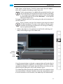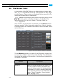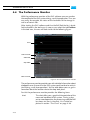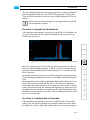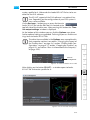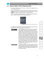
1
CLIPSTER Edit Tool User Guide (Version 2.5)
Workstation Software
CLIPSTER
Edit Tool
User Guide
CLIPSTER Edit Tool
User Guide
Introduction
1
Basics
2
Getting Started
3
The Tool Area
4
The Control Area
5
The Timeline
6
Timeline Element Properties
7
The Conforming Tool
8
The Menus
9
Appendix
A
Index
I
User Guide Version 2.5 for the CLIPSTER Edit Tool Version 2.5
Copyright © 2008-2009 by DVS Digital Video Systems AG, Hanover. All rights reserved.
The manuals as well as the soft- and/or hardware described here and all their constituent parts are
protected by copyright. Without the express permission of DVS Digital Video Systems AG any form
of use which goes beyond the narrow bounds prescribed by copyright legislation is prohibited and
liable to prosecution.
This particularly applies to duplication, copying, translation, processing, evaluation, publishing, and
storing and/or processing in an electronic system.
Specifications and data may change without notice. We offer no guarantee that this documentation
is correct and/or complete. In no event shall DVS Digital Video Systems AG be liable for any damages whatsoever (including without limitation any special, indirect or consequential damages, and
damages resulting from loss of use, data or profits, or business interruption) arising out of the use
of or inability to use the hardware, software and/or manual materials.
Those parts of this documentation that describe optional software or hardware features usually
contain a corresponding note. Anyway, a lack of this note does not mean any commitment from
DVS Digital Video Systems AG.
CLIPSTER, DVS and Spycer are registered trademarks of DVS Digital Video Systems AG. Adobe and
Photoshop are either registered trademarks or trademarks of Adobe Systems Incorporated in the
United States and/or other countries. Apple and QuickTime are trademarks of Apple Inc., registered
in the U.S. and other countries. Kodak and Cineon are trademarks of Eastman Kodak Company.
IRIX and SGI are registered trademarks of Silicon Graphics, Inc. Windows, the Windows logo and
Windows Media are registered trademarks or trademarks of Microsoft Corporation in the United
States and/or other countries.
Any other product names mentioned in this documentation may be trademarks or registered trademarks of their respective owners and as such are subject to the usual statutory provisions.
Headquarters:
DVS Digital Video Systems AG
Krepenstr. 8
30165 Hannover
GERMANY
Phone:
+49-511-67807-0
Fax:
+49-511-630070
E-mail:
[email protected]
Internet:
http://www.dvs.de
Support:
Phone:
+49-511-67807-25
Fax:
+49-511-67807-31
E-mail:
[email protected]
For the Americas:
U.S. Headquarters:
DVS Digital Video, Inc.
300 East Magnolia Boulevard, Suite 102
Burbank, CA 91502
USA
Phone:
+1-818-846-3600
Fax:
+1-818-846-3648
E-mail:
[email protected]
Internet:
http://www.dvsus.com
Support:
E-mail:
[email protected]
Contents
1
Introduction ............................................................................... 1-1
1.1
1.2
1.3
1.4
1.5
2
C
Overview ............................................................................. 1-4
Target Group ........................................................................ 1-5
Conventions Used in this User Guide .................................... 1-6
Important Notes ................................................................... 1-7
New in the Edit Tool ............................................................. 1-8
Basics .......................................................................................... 2-1
2.1
2.2
2.3
2.4
Overview of the Software Structure ..................................... 2-2
Overview of the User Interface ............................................ 2-6
The Task Bar ......................................................................... 2-9
Working in Real Time ......................................................... 2-11
2.4.1 Working with Proxies ................................................ 2-11
2.4.2 Working with Prerendered Data .................................. 2-12
2.5 Notes on Project Management ........................................... 2-14
2.6 Notes on Source Timecode and Keycode ............................ 2-15
2.6.1 About Source Timecode ............................................. 2-15
2.6.2 About Keycode ......................................................... 2-16
2.7 About Timecode / Frame Number Fields ............................ 2-17
3
Getting Started .......................................................................... 3-1
3.1 Starting the Program ............................................................ 3-2
3.2 First Steps in the Edit Tool ..................................................... 3-3
3.2.1 Preparing the Bin ........................................................ 3-3
3.2.2 Adding Clips to the Timeline ......................................... 3-6
3.2.3 Changing the View of the Timeline ................................ 3-9
3.2.4 Moving Clips in the Timeline ...................................... 3-10
i
CLIPSTER Edit Tool User Guide
3.2.5
Manipulating In- and Outpoints in the Timeline ............ 3-11
3.2.6
Adding a Transition to the Timeline ............................. 3-13
3.2.7
Applying Effects to Clips in the Timeline ....................... 3-15
3.3 Exiting the Program ............................................................ 3-18
4
The Tool Area ............................................................................ 4-1
4.1 Changing the Size of the Tool Area....................................... 4-2
4.2 The Bin ................................................................................. 4-3
4.2.1 Configuring the Bin ..................................................... 4-4
4.2.2 Adding Clips to the Bin ................................................ 4-6
4.2.3 Details about Clips .................................................... 4-10
4.2.4 Working with Folders in the Bin .................................. 4-14
4.2.5 Working with Clips in the Bin ...................................... 4-16
4.2.6 Using Proxies ............................................................ 4-22
4.3 Effects ................................................................................ 4-25
4.3.1 Adding Effects to the Timeline .................................... 4-25
4.3.2 Creating Preset Effects ............................................... 4-26
4.3.3 Using Preset Effects ................................................... 4-28
4.3.4 Administration of Preset Effects ................................... 4-29
4.4 Jobs .................................................................................... 4-33
4.5 The Marker Table ............................................................... 4-34
4.6 The Performance Monitor .................................................. 4-36
4.6.1 The Chart ................................................................. 4-38
4.6.2 Chart Controls .......................................................... 4-40
4.6.3 The Status Bar ........................................................... 4-41
4.6.4 The Drop Table ......................................................... 4-42
4.6.5 The Table Controls .................................................... 4-43
4.6.6 Using the Performance Monitor .................................. 4-44
5
The Control Area ...................................................................... 5-1
5.1 The Video Overlay ............................................................... 5-2
5.1.1 Configuring the Video Overlay ..................................... 5-2
5.1.2 The Video Scopes ........................................................ 5-3
5.2 The Scrub Bar of the Control Area ........................................ 5-9
5.3 Controls ............................................................................. 5-11
5.4 The Source-Edit Mode ........................................................ 5-14
5.4.1 Controlling the Clip from the Bin ................................. 5-16
5.4.2 Setting In- and Outpoint for the Clip from the Bin ......... 5-18
ii
Contents
5.4.3 Processing the Source Material of a Video Clip .............. 5-21
5.5 The Trim Mode .................................................................. 5-24
5.5.1 The Trim Controls ...................................................... 5-25
5.5.2 Setting In- and Outpoints of Clips ............................... 5-27
5.6 The Slave Mode Control Window....................................... 5-29
6
The Timeline .............................................................................. 6-1
6.1 Adding Clips to the Timeline ................................................. 6-2
6.1.1 Taking a Clip Directly from the Bin ................................ 6-2
6.1.2 Taking a Clip from the Control Area .............................. 6-4
6.2 Configuring the Timeline ...................................................... 6-6
6.2.1 Changing the Layout of the Timeline Area ..................... 6-6
6.2.2 Changing the Appearance of Video Clips ....................... 6-8
6.2.3 Configuring the Timeline Scale ...................................... 6-9
6.2.4 Configuring the Tooltips of Clips ................................. 6-10
6.2.5 Changing the Display Type ......................................... 6-10
6.2.6 Configuring the Video and Audio Output .................... 6-12
6.2.7 Further Audio Configurations ..................................... 6-17
6.2.8 Loading and Applying a 3D LUT File ........................... 6-18
6.2.9 Cropping the Timeline ............................................... 6-21
6.2.10 Burn-in Information at the Output(s) ........................... 6-25
6.2.11 Naming Tracks .......................................................... 6-28
6.3 Controlling the Timeline ..................................................... 6-29
6.3.1 Moving within the Timeline ........................................ 6-29
6.3.2 Setting an In- and Outpoint for the Timeline ................ 6-32
6.3.3 The Insert/Overwrite Mode of the Timeline .................. 6-34
6.3.4 Muting and Locking Tracks ......................................... 6-36
6.4 Working with the Timeline in General................................. 6-38
6.4.1 Moving Clips within the Timeline ................................ 6-38
6.4.2 Selecting Clips .......................................................... 6-40
6.4.3 Cutting, Copying or Pasting Clips ................................ 6-41
6.4.4 Adding Clips of a Certain Length to the Timeline .......... 6-41
6.4.5 Deleting Timeline Elements in a Specified Range ........... 6-42
6.4.6 Performing a Cut ...................................................... 6-44
6.4.7 Setting Transitions ..................................................... 6-44
6.4.8 Prerendering of Timeline Elements ............................... 6-46
6.4.9 Changing In- and Outpoints of Timeline Elements ......... 6-47
6.4.10 Advanced Trimming .................................................. 6-50
6.4.11 Marking Positions in the Timeline ................................ 6-52
iii
CLIPSTER Edit Tool User Guide
6.4.12 Attaching Audio Clips to Video Clips ........................... 6-55
6.4.13 Time Stretching or Time Compression of Clips ............... 6-56
6.4.14 Relinking Clips .......................................................... 6-58
6.5 Working with Video Clips ................................................... 6-60
6.5.1 The Clip’s Information ................................................ 6-60
6.5.2 The Context Menu of Video Clips ............................... 6-61
6.5.3 Consistencies of Clips ................................................ 6-63
6.5.4 Matching an Individual Video Frame ........................... 6-64
6.5.5 Processing the Source Material of a Timeline Element .... 6-66
6.5.6 Vertical Editing of Video Clips in the Timeline ................ 6-67
6.5.7 Scene Detection ........................................................ 6-69
6.5.8 Displaying the Alpha Channel ..................................... 6-72
6.6 Working with Audio Clips ................................................... 6-74
6.6.1 The Clip’s Information ................................................ 6-74
6.6.2 The Context Menu of Audio Clips ............................... 6-75
6.6.3 Volume Control ......................................................... 6-77
6.6.4 Waveform Display ..................................................... 6-79
6.7 Finalizing the Timeline ........................................................ 6-80
6.7.1 General Settings ........................................................ 6-81
6.7.2 Configuring Video ..................................................... 6-82
6.7.3 Configuring Audio ..................................................... 6-86
6.7.4 Finalizing .................................................................. 6-88
6.7.5 The Finalized Output (Files per Folder) ......................... 6-88
6.7.6 Name Options .......................................................... 6-90
7
Timeline Element Properties ................................................... 7-1
7.1
7.2
7.3
7.4
7.5
7.6
Accessing the Timeline Element Properties ............................ 7-2
General Items of the Properties Area .................................... 7-3
Changing Values of Sliders and Entry Fields .......................... 7-5
Closing the Timeline Element Properties ............................... 7-6
Properties of a Transition ...................................................... 7-7
Properties of a Video Clip ................................................... 7-10
7.6.1 Adding Effects .......................................................... 7-11
7.6.2 Altering Effect Settings ............................................... 7-12
7.6.3 Using Preset Effects in the Properties Area .................... 7-14
7.7 The Operator ’Zoom + Pan’ ............................................... 7-16
7.7.1 Items for Zooming ..................................................... 7-16
7.7.2 Items for Panning ...................................................... 7-17
iv
Contents
7.7.3 Advanced Settings ..................................................... 7-18
7.8 Keyframing ........................................................................ 7-21
7.8.1 The Parameters List ................................................... 7-21
7.8.2 Viewing the Graph .................................................... 7-23
7.8.3 Moving within the Graph ........................................... 7-25
7.8.4 Setting Keyframes ..................................................... 7-27
7.8.5 Positioning Keyframes ............................................... 7-27
7.8.6 Further Possibilities .................................................... 7-28
7.9 The Operator ’Flip Flop’ ..................................................... 7-30
7.10 The Operator ’1st Color Correction’ ................................... 7-31
7.10.1 Static LUT ................................................................ 7-31
7.10.2 Master / Luma / Chroma ........................................... 7-32
7.10.3 Global ...................................................................... 7-34
7.10.4 Lift / Gamma / Gain .................................................. 7-35
7.10.5 Color Wheel ............................................................. 7-36
7.11 The Operator ’2nd Color Correction’ .................................. 7-38
7.11.1 Usage of the Secondary Color Correction ..................... 7-38
7.11.2 The Color Vector List ................................................. 7-41
7.11.3 The Color Mask Area ................................................. 7-42
7.11.4 The Color Correction and Balance Area ........................ 7-48
7.12 Picture Masks ..................................................................... 7-51
7.12.1 The Shapes List ......................................................... 7-51
7.12.2 Setting Shapes .......................................................... 7-52
7.12.3 Adjusting the Shapes ................................................. 7-54
7.13 The Operator ’6-Vector CC’ ............................................... 7-55
7.14 The Operator ’DeInterlace’ ................................................. 7-57
8
The Conforming Tool ............................................................... 8-1
8.1 Introduction to Conforming with the Edit Tool ..................... 8-2
8.1.1 Conforming in General ................................................ 8-2
8.1.2 The Conforming Tool and its Mode ............................... 8-2
8.1.3 Important Notes ......................................................... 8-3
8.2 First Steps to Make a Conforming ........................................ 8-6
8.2.1 Importing and Adding EDLs .......................................... 8-6
8.2.2 Building up a Timeline .................................................. 8-9
8.2.3 Conforming .............................................................. 8-13
8.2.4 Evaluation and Further Processing of the Conforming .... 8-18
v
CLIPSTER Edit Tool User Guide
8.3 Working with EDLs from the Timeline................................. 8-22
8.4 The Conforming Mode in General ...................................... 8-25
8.5 Conforming Mode – The Work Area .................................. 8-27
8.5.1 Viewing EDLs ............................................................ 8-27
8.5.2 Adapting the Appearances of the Tables ...................... 8-28
8.5.3 Changing Values and Entries ....................................... 8-28
8.5.4 The Tab ’EDLs’ .......................................................... 8-29
8.5.5 The Tab ’EDL Clips’ .................................................... 8-31
8.5.6 The Tab ’EDL Reels’ ................................................... 8-36
8.5.7 The Tab ’Original EDL’ ............................................... 8-38
8.6 Conforming Mode – The Conforming Controls .................. 8-40
8.6.1 The Edit Controls ....................................................... 8-40
8.6.2 The View Controls ..................................................... 8-41
8.6.3 The Modify Controls .................................................. 8-44
8.6.4 The Execute Controls ................................................. 8-49
8.7 Conforming Mode – The Preview Area ............................... 8-60
8.7.1 Selecting Contents for Viewing ................................... 8-61
8.7.2 The Video Overlay .................................................... 8-61
8.7.3 The Scrub Bar ........................................................... 8-62
8.7.4 The Preview Controls ................................................. 8-63
8.7.5 Clip Properties .......................................................... 8-64
8.7.6 Working with Split Screen .......................................... 8-64
8.7.7 Recreating Edit Points for an Offline Edited Clip ............ 8-67
8.7.8 Resolving Multiple Found ........................................... 8-67
9
The Menus ................................................................................. 9-1
9.1 The Menu of the Program Icon ............................................ 9-2
9.1.1 Minimize ................................................................... 9-2
9.1.2 Exit ........................................................................... 9-2
9.2 The ’Project’ Menu ............................................................... 9-3
9.2.1 New ......................................................................... 9-3
9.2.2 Open… ..................................................................... 9-4
9.2.3 Recent files ................................................................ 9-5
9.2.4 Insert Project… .......................................................... 9-5
9.2.5 Add EDL… ................................................................ 9-6
9.2.6 Add clips… ................................................................ 9-6
9.2.7 Save ......................................................................... 9-6
9.2.8 Save As… .................................................................. 9-7
9.2.9 Update CineReel ........................................................ 9-7
vi
Contents
9.2.10 Export EDL… ............................................................. 9-8
9.2.11 Finalize… ................................................................ 9-14
9.2.12 Prerender all ............................................................ 9-15
9.2.13 Extract files… .......................................................... 9-15
9.2.14 Load KDM… ........................................................... 9-16
9.2.15 Exit ......................................................................... 9-16
9.3 The ’Edit’ Menu ................................................................. 9-17
9.3.1 Undo ...................................................................... 9-17
9.3.2 Redo ...................................................................... 9-17
9.4 The ’Bin’ Menu .................................................................. 9-18
9.4.1 Import Bin… ............................................................ 9-18
9.4.2 Export Bin… ............................................................ 9-19
9.4.3 Clear Bin ................................................................. 9-19
9.4.4 Check Bin ................................................................ 9-19
9.4.5 Generate proxies ...................................................... 9-21
9.4.6 Delete all proxies ...................................................... 9-22
9.4.7 Activate all proxies ................................................... 9-22
9.4.8 Deactivate all proxies ................................................ 9-23
9.5 The ’Options’ Menu ........................................................... 9-24
9.5.1 Driver connect ......................................................... 9-24
9.5.2 Project config… ....................................................... 9-24
9.5.3 Defaults… ............................................................... 9-25
9.5.4 Load defaults… ....................................................... 9-25
9.5.5 Save defaults… ........................................................ 9-26
9.6 The ’Help’ Menu ................................................................ 9-27
9.6.1 About ..................................................................... 9-27
9.6.2 Manuals .................................................................. 9-27
A
Appendix ....................................................................................A-1
A.1
A.2
A.3
A.4
A.5
Glossary of Terms .................................................................A-1
Keyboard Shortcuts ..............................................................A-7
Supported File Formats .........................................................A-9
1D LUT Files .......................................................................A-13
3D LUT Files .......................................................................A-14
A.5.1 General Description ...................................................A-14
A.5.2 3DL Files ..................................................................A-15
A.5.3 XML Files .................................................................A-17
vii
CLIPSTER Edit Tool User Guide
A.6 Slave Mode / RS-422 Control .............................................A-18
A.7 System Maintenance ..........................................................A-19
A.7.1 The Automatic Defragmentation Process ......................A-19
A.7.2 Cleaning Temporary Data Manually .............................A-21
I
viii
Index ............................................................................................. I-1
Introduction
1
This documentation describes how to use the Edit Tool of CLIPSTER,
the real-time conforming and finishing system manufactured by DVS.
CLIPSTER is a powerful high-resolution video workstation with enormous flexibility, especially designed to meet the demands of modern
post production houses.
CLIPSTER offers capturing, online editing and storing of digital film and
audio data in one device. The system performs all works in real time.
Video data is stored and worked with in its original uncompressed format, independent of resolution, color space and bit depth. All formats
and resolutions can be processed, from SD up to 4K, and the final result
can be played out in a freely selectable format. Conversions and calculation times for render processes are rarely necessary because of the
high-quality hardware developed by DVS. Additionally, up to
16 channels of audio can be in- or output by CLIPSTER and their data
can be accessed and processed in the software as easily as the video
material. All video and audio data are stored in the Windows file system
and thus accessible right away when working with other applications.
The Edit Tool of CLIPSTER is the main part of the DVS software package. It is a software module that enables you to add video and audio
clips to a timeline in any sequence you like and in a freely configurable
number of tracks. When working with video you can edit your material
with cuts, dissolves, wipes, etc. and scalings, pannings, zoomings,
and/or color corrections. Thus you can create your perfect project.
When working with audio, you can control the volume of a clip at every
position in the timeline, for example, to create fade-ins and -outs. During all times your original material is never touched or altered because
all editing processes are performed virtually. Of course, to provide for
the best possible integration the Edit Tool is compatible with the EDL
(edit decision list) standard and supports it via import and export functions. For conforming there is also an advanced conforming tool available. Once your project is finished, you can finalize it and save the
edited clips in any video and file format you like.
In short, the Edit Tool of CLIPSTER offers:
– Easy and intuitive handling of the user interface,
1-1
1
2
3
4
5
6
7
8
9
A
I
CLIPSTER Edit Tool User Guide
–
–
–
–
–
–
–
–
–
–
–
–
–
–
clips can be moved via drag and drop,
user friendly designed timeline including editing functions,
total control of the editing process via a real-time video overlay,
project-oriented and adaptable clip management including thumbnail function,
different formats are allowed in one project (multi-format editing),
real-time view of timeline,
EDL import and export function,
projects can be built up via import or loading of an EDL,
advanced conforming tool (conforming mode of the control area),
projects can be finalized to a clip (render function),
automatic and adaptable scaling of video material in the timeline,
archive function which copies the files used in a project to a new
location thereby reducing it to the necessary data only,
full audio support, and
an automatic defragmentation of the video storage for an optimized real-time performance.
Furthermore, there are several features optionally available for the Edit
Tool which allow you to adapt the DVS software to your special needs.
The following options are available:
JPEG2000 Upgrade Kit
DCI Upgrade Kit
3D LUT and Color Management
12 Bit
4K Workflow
Color Correction Panel
1-2
Hardware accelerated JPEG2000 compression and real-time play-out of
JPEG2000 encoded material.
Complete workflow for DCI compliant
delivery packages, including hardware
accelerated JPEG2000 compression, AES
encryption as well as MXF wrapping, and
real-time play-out of JPEG2000 compressed MXF material.
Three-dimensional hardware look-up table for real-time color management and
film-look preview/output.
Support of 12- and 16-bit file formats
(DPX and TIFF) for in- and output.
Real-time play-out of 4K material including among others real-time effects (e.g.
zoom and pan and primary color correction) and non-real-time capturing.
Tactile colorist control panel in a standard
or deluxe variant for CLIPSTER’s primary
color correction.
Introduction
Multi-Device
Raster
Special Raster Formats
Remote Zoom & Pan
Secondary Color Correction
Enables a synchronous play-out/record of
multiple DVS systems. One master device
controls other devices via RS-422 for a
synchronous play-out of the timeline or
capturing with the Manual record/VTR
task mode of the I/O Tool.
Customer tailored video rasters for inand output.
Some standard and non-standard formats
including 1080p /50/60 (SMPTE 372),
Slow PAL 625i /24 and Eureka
1980 × 1152i /25.
Remote control of real-time zoom and
pan operations from a third-party color
grader.
Secondary color correction as an effect
for video clips in the Edit Tool.
1
2
3
4
5
6
7
8
9
A
I
1-3
CLIPSTER Edit Tool User Guide
1.1 Overview
This user guide informs you about the general handling of the Edit Tool
as well as of its complete controllable interface.
The chapters in this user guide contain the following information:
1-4
Chapter 1
Begins with a short introduction to CLIPSTER
and the Edit Tool, followed by a note regarding
the audience this manual is written for and an
explanation of the conventions used in this
manual. Additionally, it provides important
notes that you should read.
Chapter 2
Contains basic information about the Edit Tool.
Here you can find information about the software structure as well as a first overview of the
user interface of the Edit Tool. Furthermore,
this chapter provides some general notes, for
example, about how to manage projects with
the DVS software.
Chapter 3
In addition to the information how to start and
exit the program, you can find a beginner’s tutorial which explains shortly how to work with
the Edit Tool and how to start your first project
in this chapter.
Chapter 4
Explains the tool area of the Edit Tool.
Chapter 5
This chapter describes the control area and the
video overlay of the Edit Tool.
Chapter 6
In this chapter the timeline of the Edit Tool and
timeline related tasks are described.
Chapter 7
This chapter explains and describes the timeline
element properties of video clips and transitions. Individual effects that a video clip may
provide are explained as well.
Chapter 8
Describes the conforming tool with all its features, and details how to conform data lists
(e.g. EDLs or cut lists) with the Edit Tool.
Chapter 9
Provides information about the individual
menu options of the menu bar of the Edit Tool.
Introduction
Appendix
Gives additional information about the software. Among others you can find here a glossary of terms used in this user guide and the file
formats that are supported by the DVS software.
Index
This chapter facilitates the search for specific
terms.
1.2 Target Group
To use this user guide and the Edit Tool correctly you should have experience in PC handling and be familiar with the hardware handling of
a video system. If you want to use the software to its full potential, you
should also have extensive knowledge in the field of digital video.
Furthermore, to use the DVS system in connection with other equipment, e.g. a VTR, you should know how to handle this equipment.
1
2
3
4
5
6
7
8
9
A
I
1-5
CLIPSTER Edit Tool User Guide
1.3 Conventions Used in this User Guide
The following typographical conventions will be used in this documentation:
y Texts preceded by this symbol describe activities that you must perform in the order indicated.
– Texts preceded by this symbol are parts of a list.
Texts preceded by this symbol are general notes intended to
facilitate work and help avoid errors.
You must pay particular attention to text that follows this
symbol to avoid errors.
“ ” Texts enclosed by quotation marks are references to other manuals, guides, chapters, or sections.
’Window’
Text in bold with single quotation marks indicates a window name
BUTTON
Text in small caps and bold indicates push buttons
Text in italic and bold indicates either a group
name, menu name or options in a menu list
In the specified group or menu select the stated
item
Text in bold only stands for other labeled items
of the user interface
Directory structure or file
Parameters, selections or entries made in the
program; it may also indicate a file syntax or
contents of a file
An individual key or a key combination on a
keyboard
Group/Menu
Menu » Option
Item
File
Entry
[Key]
Keyboard Shortcuts
To perform options or procedures with the keyboard often requires a simultaneous pressing of two keys.
Example:
[Ctrl + F1]
1-6
If this is given, hold down the [Ctrl] key and
press simultaneously the [F1] key.
Introduction
1.4 Important Notes
Please observe the following while using the Edit Tool:
Only use the designated video drive (main storage) to store
video and audio data. Other storage locations will be too slow
for real-time operations.
Leave about 15 % of the overall main storage capacity empty
of data for real-time performance reasons.
The real-time capability of CLIPSTER depends to a large extent on the performance of the system’s hardware. Therefore,
it is recommended to terminate all other programs when
working with the DVS software.
After copying or recording large amounts of data to the main
storage, it is recommended to leave the DVS software running
for a longer period of time (e.g. over night) without performing any real-time tasks (play-out or record) or having the slave
mode/VTR task mode activated. This will give the built-in defragmentation tool time to reorganize the files on the storage
for an optimized real-time performance. For this the automatic starting of the defragmentation tool has to be enabled.
Your DVS system has been tested thoroughly and is very reliable. However, because of the vast amount of third-party
software available, its reactions on the installation of such
could not be tested. The installation of third-party software
may disrupt the real-time capability and/or limit the functionality of your system.
When working with prerendered files and timeline elements
that need a prerendering, it is recommended to activate the autosave function of the DVS software and set it to a relatively
short interval.
1
2
3
4
5
6
7
8
9
A
I
1-7
CLIPSTER Edit Tool User Guide
1.5 New in the Edit Tool
The following lists the most important features and functions that were
new in the latest versions of the Edit Tool:
Please note that the features and functions mentioned may be
part of optional packages.
For further information please refer to the release notes of the
DVS software.
New in Version 2.5
– Comprehensive tool for an easy and fast conforming (conforming
mode of the control area)
– Updated export to EDL
– Smaller changes to keyframing
– Adaptable frame numbering for name options during finalizing
– Automatic creation of metadata file (SequenceInfo.xml) during
finalizing/capturing for multi-clip detection
– Display of alpha channel of individual timeline clips in the video
overlay and at the video outputs
– Presets for time stretching and time stretching for audio
– Relinking of clips in the timeline
– Consistency check of clips allows to change the software’s default
paths to find clips of projects exchanged between systems
New in Version 2.4
– DCI Mastering (see the “CLIPSTER DCI Mastering” supplement
accessible via the software’s online help)
– Variable information in file names for finalizing (name options)
New in Version 2.3
– Scene detection
– Render times for prerendering and finalizing approx. two times
faster
– Real-time effects can be finalized at least in real-time speed
– Background rendering (tab Jobs of the tool area)
– 6-vector color correction
– Marker list with thumbnails
– ’Adaptive+’ scaling algorithm
New in Version 2.2
– Color scheme for prerendered clips
– Enhanced output settings for SDI and DVI/analog
– Lin-to-Log conversion for 3D LUTs
1-8
Introduction
– Slave mode remote control switchable between different protocols
– More than 100 graphic file formats for import/adding
New in Version 2.1
–
–
–
–
–
–
–
Archive function via the Extract files… menu option
Bin clip properties accessible from timeline (context menu)
Keyframing for Zoom & Pan
Burn-in information at the outputs
Slave mode control window
Configurable keyboard shortcuts (function keys) for preset effects
Picture masks (shapes) for secondary color correction
1
2
3
4
5
6
7
8
9
A
I
1-9
CLIPSTER Edit Tool User Guide
1-10
Basics
2
The Edit Tool is one of the software modules of the DVS software and
thus part of the software package for CLIPSTER. This chapter provides
first some background information about the structure of the DVS software which includes a short overview of its different modules. After
that an overview of the user interface of the Edit Tool is provided to familiarize you with its appearance. This will be followed by a description
of the task bar of the software. The chapter will be concluded with
some general notes, for example, about how to manage projects with
the DVS software.
1
2
3
4
5
6
7
8
9
A
I
2-1
CLIPSTER Edit Tool User Guide
2.1 Overview of the Software Structure
The software package for the DVS system consists of various individual
programs and modules that combined provide the system’s unique capabilities to process digital video and audio in real time. The following
diagram shows the communication processes between individual software parts and some hardware components in detail:
DVS System
Hardware
Software
Edit
Tool
I/O
Tool
Tools
Hard Disk Array
Integrated
Spycer
Configuration
Tool
User Interface
OpenFX
Plug-Ins
PCI
PCI Video Board
1
2
3
4
O
N
O
N
1
2
3
4
1
2
3
4
5
6
7
8
PCI Video
Board Driver
O
N
Software
Figure 2-1: Structure of software
Although the graphic shows a software and a hardware side of
the video system, this is only an abstraction of the real video
device to show the ways of communication within the system.
Video Board and Driver
The central core of the whole system is the DVS PCI video board and
its driver because they provide the functionality of the video system.
Without them the system would not be able to display any video signals
nor would the DVS software components be operational.
The PCI video board driver controls the video board and thus the inand output of video signals. It runs in the background of your video system and is therefore not visible.
Software User Interface and Software Modules
The software user interface is the visible part of the DVS software package. It consists of individual software modules which control the DVS
2-2
Basics
system and are used to perform editing and video as well as audio processing tasks. These modules are the Edit Tool, the I/O Tool, the Configuration Tool, and Spycer, the innovative content management
software by DVS. They are the basic software modules of the DVS system, i.e. the ones that you will use most in your every day work. You
can see them in the drawing above in the oval ’Software User Interface’.
Depending on your system configuration there may be other
tools and modules available on your system. Further information about these can be found in their respective user guides.
Once the DVS software is started, you can access the different
modules available on your system easily via the task bar of the
user interface (see section “The Task Bar” on page 2-9).
The Edit Tool
The Edit Tool is the software module that allows you to assemble video
material by adding cuts, dissolves, wipes, etc. as well as audio material
on a timeline. In the timeline you can add clips of different formats and
resolutions and process them, for example, via color corrections, scalings or zooming and panning. Additionally, in this module you can perform a DCI Mastering and create properly encoded and encrypted
digital cinema packages (DCPs, see the “CLIPSTER DCI Mastering”
supplement accessible via the software’s online help). The Edit Tool
module is compatible with the EDL (edit decision list) standard and supports it via its sophisticated conforming tool, allowing you, for example,
to import EDLs, conform them, work with the built-up timeline freely,
and afterwards export your work to a new EDL. One of the main features of the Edit Tool is that all editing tasks are performed virtually, i.e.
the original material on the storage is never altered. The clips used in
the DVS software are only representations of the original material on
the storage. With this you can use the same material over and over
again with different effects while the master is always maintained.
1
2
3
4
5
6
7
8
The I/O Tool
The I/O Tool is mainly used for the digitization of a variety of different
input sources, meaning the recording/capturing of video and audio
data with the DVS system from other sources than computer storages.
You can capture material from any source you like and record it in a
freely selectable format, with or without color space conversion. For instance, you can capture data from telecines, VTRs, or even cameras –
as desired in an automated batch processing mode or manually. Of
course, playing out the recorded material as well as of all other clips
present on the system can be performed without any effort as well. Furthermore, the processing of EDLs is fully supported in the software, for
2-3
9
A
I
CLIPSTER Edit Tool User Guide
example, via import and export functions (import via the I/O Tool and
export via the Edit Tool).
Integrated Spycer
With Spycer, the innovative content management software by DVS,
you can manage your content easily. It is a software application capable
of handling large amounts of video data and their corresponding metadata, providing you with integrated browse, search and management
tools to retrieve data and gather information about them locally as well
as via a network. Additionally it can be used to preview clips and add
them to the bin of the DVS software, thus offering you even more possibilities than a file manager. Spycer is already integrated in the DVS
software. It can be accessed the same way as the other software modules and is thus not needed as a stand-alone application. For CLIPSTER
users it comes with the complete feature set and, furthermore, works
seamlessly together with other available DVS products, such as the
DVS-SAN.
The Configuration Tool
For the configuration and setup of the whole DVS system and its software you can use the Configuration Tool. Here you can set up, for example, the period for the automatic save function of the project file
(autosave) as well as more software specific settings, such as the bin
properties.
Tools and Services
Also part of the DVS software are various tools that can be used for a
more basic configuration of the DVS system or may be of help during
service and maintenance tasks, e.g. monitoring and error diagnostics of
the hard- and software.
For instance, among them you can find the defragmentation tool which
is a process automatically started with the DVS software and running in
the background of the system. During stand-still times of the system
the defragmentation tool will reorganize the files present on the storage
for an optimized performance of real-time tasks such as a play-out or
record. Among the tools it is the only process that runs in the system’s
background.
2-4
Basics
Most other tools delivered with the DVS software are used during the
initial configuration and setup of the system only. In your daily work
with the DVS system they are of no use.
Further information about the tools in general can be found in
the “CLIPSTER Tools and Services” user guide accessible via
the PDF files of the software’s online help. For additional information about the defragmentation process in particular please
refer to section “The Automatic Defragmentation Process” on
page A-19.
Plug-Ins (Operators)
The Edit Tool of the DVS software supports the OpenFX plug-in interface providing you with the possibility to extend the software module’s
effects feature set with plug-ins developed by third parties. The various
available OpenFX plug-ins offer you additional editing possibilities for
your video processing tasks, such as color correction or image processing. Once installed, they can be accessed in addition to the standard effects operators as timeline element properties of clips. Further
information about this can be found in section “Timeline Element Properties” on page 7-1.
1
2
3
4
5
6
7
8
9
A
I
2-5
CLIPSTER Edit Tool User Guide
2.2 Overview of the User Interface
The following figure shows the user interface of the Edit Tool as it appears after starting the DVS software (for information on how to start
the software see chapter “Getting Started” on page 3-1):
menu bar
tool area
task bar
control area
timeline area
Figure 2-2: User interface of the Edit Tool
The DVS software is designed to run in full-screen mode to
provide for an undistracted view on the video material and the
editing task at hand. To switch to the operating system environment use the [Windows (
)] key on your keyboard or select from the menu of the program icon on the menu bar the
menu option Minimize (see section “Minimize” on page 9-2).
Via the check box Don’t show this message again offered
by information messages of the DVS software you can deactivate the appearance of this particular message for the current
software session (i.e. next session it will be displayed again).
2-6
Basics
After starting the DVS software the Edit Tool software module is activated automatically. Here you can see the following items:
menu bar
tool area
control area
timeline area
At the top of the user interface you can find a menu
bar. This menu bar provides access to functions and
tasks of an administrative nature for the DVS software.
Here you can find, for example, import and export
functions as well as several menu options generally
concerned with projects and project files. A description
of the menu bar can be found in chapter “The Menus”
on page 9-1.
Directly below the menu bar you can find the tool area
which may show you depending on the currently active
software module and/or on the optional features available various tools that can be used during your work
with the system. The tools are provided as tabs to
switch easily between them. By default you can find
among the tools, for example, the bin which provides
initial access to the video material. For more details
about the tool area and the individual tools see chapter
“The Tool Area” on page 4-1.
To the right of the tool area you can find the control area. In the Edit Tool this area is used to pre- and review
your current project. At the top you can find the video
overlay where you can see the video material. Below
the video overlay a scrub bar of the timeline is available. In contrast to the timeline in the timeline area
where you can zoom in and out, the scrub bar always
shows the complete timeline of the project. Below the
scrub bar the controls are located to play out and move
within your current project. Here you can also find buttons to switch between the different modes of the control area: the edit mode, the source-edit mode, the trim
mode, and the conforming mode. The control area will
be described in chapter “The Control Area” on
page 5-1.
In the timeline area you can find the video and audio
tracks. Most of the editing tasks are performed here,
for example, by setting cutting points and defining operators. The timeline area can be configured freely and
thus be adapted to your individual needs. This area and
how to work with projects in the timeline are explained
in chapter “The Timeline” on page 6-1.
2-7
1
2
3
4
5
6
7
8
9
A
I
CLIPSTER Edit Tool User Guide
task bar
2-8
The user interface provides at its bottom a task bar
where you can switch between the different software
modules of the DVS software. The task bar is available
in most modules and you can easily start and switch
between them. It will be described in more detail in section “The Task Bar” on page 2-9.
Basics
2.3 The Task Bar
The user interface provides at its bottom a task bar where you can
switch between the different software modules of the DVS software.
The task bar is available in most modules and with it you can easily
switch to another module.
After starting the DVS software the Edit Tool is started automatically
(
). When you click on one of the inactive buttons in the
task bar, the respective software module will be loaded, most of them
in the upper part of the user interface. The task bar provides the following buttons:
The EDIT button activates the Edit Tool of the DVS
software. This software module allows to edit video
material with effects like color correction, zooming
and panning, 3D LUTs, or cropping. Additionally, in
this module you can perform a DCI Mastering. It is
automatically active after starting the software and
described in this user guide.
The I/O button starts the I/O Tool of the DVS software. You can use it to capture video and audio material with the DVS system from telecines, VTRs, or
cameras. You can find further information about the
I/O Tool in the “CLIPSTER I/O Tool” user guide.
With the button SPYCER you can activate the local
content management software by DVS where you
can browse and/or search for data on local and network storages. Its management tools allow you, for
example, to defragment data as well as to define or
alter metadata. Additionally, you can preview clips
and add them to the bin of the DVS software by a
simple drag-and-drop procedure. Spycer is described in the “Spycer” user guide.
The CONFIG… button opens the Configuration Tool.
Here you can configure and set up the whole video
system and the software. With it you can, for example, set up the period for the automatic save function of the project file (autosave) as well as more
software specific settings, such as the bin properties.
More information about the Configuration Tool as
well as various other configurations that can be performed can be found in the “CLIPSTER Configurations” user guide.
For a more detailed description of all basic software modules as
well as other parts of the software together with references to
their descriptions, please refer to section “Overview of the
Software Structure” on page 2-2.
2-9
1
2
3
4
5
6
7
8
9
A
I
CLIPSTER Edit Tool User Guide
Additionally, you can find at the bottom right of the task bar several
items which will provide you with information about the currently loaded project, the duration of its timeline in total and the set video output
format for the timeline:
project information
Figure 2-3: Project information
The timeline’s duration shows you the duration of all clips present in the
timeline tracks and depends on the currently selected video output raster (frame rate).
Furthermore, to the right of the task bar you can find some status messages. They will be displayed as soon as project relevant tasks are performed, for instance, when a project is loaded or saved.
status and
help messages
Figure 2-4: Status and help messages of the DVS software
As well, this part of the task bar will provide you with help information
about the various menu options available via the menu bar of the DVS
software. The help information will be displayed when you place the
mouse cursor over one of the menu options.
2-10
Basics
2.4 Working in Real Time
With the DVS system you can perform most operations in real time.
When playing out or recording, the workstation is capable of handling
two data streams of 2K material for transitions in real time.
Using CLIPSTER you can even play out one stream of 4K material in real
time as long as some conditions are observed: To play out 4K you will
need an appropriate hardware equipment (CLIPSTER 4K) and the resolution of the clip should not exceed 4096 × 3112 pixels (10 bit). With
this a real-time play-out of 4K material is possible. The usage of a
3D LUT, cropping, zoomings and pannings, and primary color corrections, can also be performed in real time.
However, other effects (e.g. secondary color correction) or clips of an
even higher resolution cannot be processed in real time. In such a case
the DVS system offers you two different approaches to maintain a realtime workflow as long as possible: You can work with proxies or you
can prerender the material and/or operators prior to a play-out.
When working with proxies or prerendered files, additional
data (image files) will be created on your main storage. It is recommended to store these project specific for each project separately. For further information about this please refer to
section “Notes on Project Management” on page 2-14.
You can set the storage location of such files for each project
differently via the Configuration Tool on the tab Project
(group Project, field Path for proxy data; see “CLIPSTER
Configurations” user guide).
1
2
3
4
5
6
2.4.1 Working with Proxies
A proxy is a downscaled clip of a higher resolution (greater than 2K).
Usually, proxies will be used as a substitute when working with highresolution film material, such as 4K. Then the original data will be
downconverted to a 2K format that can be handled by the DVS software and system in real time without problem.
7
In this workflow you will add the 4K clips as usual to the bin. But prior
to using them in the timeline you will create proxies of them. The
downconverted images of the proxy will be stored in a reserved location for temporary data on the main storage.
9
The stored proxies carry project specific file names that are generated
and administered by the Edit Tool automatically for the currently loaded
project. The links to the proxies will be stored in the project file, and
when reopening the project again you will not have to create them
again. When working with proxies, a lot of image files may be generated amounting to a large proportion of disk space.
2-11
8
A
I
CLIPSTER Edit Tool User Guide
Once a proxy has been created, it will be available in the bin instead of
the original high-resolution clip. Nevertheless, the bin clip and all its
representations in the timeline are still linked to its original material and
by turning the proxies on or off it is for you to decide whether the material of the higher resolution is used or the proxies. Thus you can work
with the downconverted clips as usual in the timeline but when playing
out or finalizing you can switch back to the original material in high resolution.
4K Display
(2 × single-link DVI)
Scanner
Storage Array
# Working with 2K proxies
# Finalizing with 4K original
# Display of one 4K stream
4K Files
2K Proxies
Film Printer
4K Files
Figure 2-5: Possible workflow when using proxy data
With this workflow you will be able to finish a conformed 4K project
with 2K proxies in real time by using color correction, zooming as well
as panning and/or other editing features. Once your job is done, the
DVS system can finalize (render) the whole project from the original 4K
material. Afterwards to check the rendered 4K master you may play it
out in real time provided your system is capable of a real-time handling
of 4K.
To recognize the downscaled data belonging to one project
easily it is recommended to store it project specific for each
project separately. For further information about this please refer to section “Notes on Project Management” on page 2-14.
More information about the handling of proxies in the DVS
software can be found in section “Using Proxies” on
page 4-22.
2.4.2 Working with Prerendered Data
Prerendering generates another kind of proxies, this time from clips and
operators added to the timeline that are not real-time capable. A prerendering means that the Edit Tool calculates the respective clips and operators (effects) before a play-out takes place and stores the calculated
extra files (rendered images) in a location for temporary data on the
2-12
Basics
main storage. These proxies are then used for a play-out instead of the
original material in the timeline and on-the-fly handled operators.
Depending on your system capabilities all timeline elements, i.e. clips as
well as operators (such as transitions or color corrections), can be subject to a prerendering. For example, when using a clip of a resolution
that exceeds the real-time capability of your DVS system, it will be
marked visibly in the timeline that it is not real-time capable. In order to
play it out in real time you will have to prerender it beforehand and it
will be rendered in the format that is currently set as the video output
format. The prerendered proxies carry project specific file names same
as the proxies created from the bin and are generated and administered
by the Edit Tool automatically. The links to prerendered proxies will be
stored in the project file, and when opening the project later again, it
will not be necessary to render them anew.
When working with prerendered data you may get proxies on the storage that are no longer required for your current project but occupying
disk space. This will happen, for example, as soon as a timeline element
was prerendered and afterwards deleted or changed. Even a switching
of the video format will make the already prerendered data obsolete
due to the fact that the extra images may no longer coincide with the
newly selected format. Because the software can never be sure when
proxies are truly obsolete for a project, they will remain on the storage
of your system. Nevertheless, to delete prerendered data you can use
the menu option Delete prerendering on the context menu of a video
clip (see section “The Context Menu of Video Clips” on page 6-61).
To recognize the prerendered data belonging to one project
easily it is recommended to store them project specific for each
project separately. For further information about this please refer to section “Notes on Project Management” on page 2-14.
Related to a prerendering of timeline elements are the Prerender all menu option on the menu Project (see section “Prerender all” on page 9-15) and the section “Real-time Capability
of Clips” on page 4-13, section “Jobs” on page 4-33 and section “Prerendering of Timeline Elements” on page 6-46.
1
2
3
4
5
6
7
8
9
A
I
2-13
CLIPSTER Edit Tool User Guide
2.5 Notes on Project Management
To display material of a very high resolution or to enable a real-time
play-out of some operators (e.g. the secondary color correction) the
DVS system may create proxies as well as prerendered files. Both ways
to maintain a real-time workflow are based on the same principle: They
use calculated extra files to either enable a play-out (prerendering) or
make your working environment more comfortable (proxy generation).
For further information about proxies or prerendered data see
section “Working in Real Time” on page 2-11.
The location where these extra files are stored is saved project specific
in the project file, i.e. each project file can have a different directory for
proxy data and the exact location will be stored in the project file.
Therefore, it is suggested when working with proxies or prerendered
material, to store the project’s data in a directory of its own. DVS recommends, when working with different projects, to create for each
project a project specific directory on your main storage where to save
the project file. Beneath it create a subdirectory for the additional data:
V:
<project specific directory>
<proxy data directory>
<project file>.cp
This structure guarantees a clear and easy to manage project.
You can set the storage location of such data for the currently loaded
project with the Configuration Tool of the DVS software in the group
Project of the tab Project (see “CLIPSTER Configurations” user guide
as well as section “Working in Real Time” on page 2-11 for more information).
2-14
Basics
2.6 Notes on Source Timecode and Keycode
Some file formats for clips, e.g. *.dpx files, are capable of storing more
information than just their image content. These information are usually written in a specified format into the file headers which can be read
and interpreted by different software applications that support these
kind of information. Among the information stored you can find, for
example, the name of the creator (usually the program that created the
files), the creation time and date, the timecode and/or the keycode.
Most of the data stored in file headers and transmitted to the DVS software during a capturing will only be recorded and given back again
during a play-out, if appropriate. However, DVS especially makes use
of the timecode and keycode information.
The DVS software supports additional information such as
source timecode in the *.dpx, *.mov as well as *.mxf file
formats. However, some features (e.g. multiple timecodes or
the editing of header data) are available for *.dpx files only.
With the help of Spycer the header data, such as timecode or
keycode information, can be adjusted to your liking (see
“Spycer” user guide for more information).
1
2
3
2.6.1 About Source Timecode
Timecode information stored in file headers (the so-called source timecode) can be used in the whole DVS software. For example, you can
use source timecodes in the timeline of the Edit Tool and regardless of
their position in the timeline the respective clips will always show and
use their source timecode. Then, prior to a play-out you can decide
whether the internal timeline timecode should be given out as a timecode signal or the source timecodes provided by the files.
Regarding source timecode there are some peculiarities how the DVS
software deals with source timecodes. Some of them are detailed in the
following:
The image files capable of storing timecode information usually provide
space for one timecode only in their header (generic source timecode).
But because DVS systems are able to receive, for example, during a
record, several timecodes incorporated in signals at various connectors,
they use more than just one timecode. During a write procedure, i.e.
when recording clips via the I/O Tool (*.dpx files), the system will
write all received timecode information into the file headers. The ones
additionally received will be stored at a location for user defined data in
the header and usually cannot be interpreted by applications other than
the ones developed by DVS. When processing such clips afterwards, for
instance, in the timeline of the Edit Tool or when conforming, you can
2-15
4
5
6
7
8
9
A
I
CLIPSTER Edit Tool User Guide
select between the various timecodes provided by the clips which may
give you more control over their position in the timeline.
In the Configuration Tool of the DVS software you can configure the
general way the software should deal with timeline and source timecode (see “CLIPSTER Configurations” user guide for more information). Here you can set in the respective group the type of source
timecode that the DVS software will use as the default source timecode.
Additionally, you can specify which timecode should be given out when
performing a play-out.
Furthermore, throughout the DVS software individual clips may use different source timecodes which is a setting that can be adjusted in the
clip’s properties (see section “Changing the Properties of Clips” on
page 4-21). The type of source timecode used by each clip can be
changed even when the clip is already used in the timeline of the Edit
Tool. And when clips do not provide a source timecode of their own,
you can set the clips to show a virtual source timecode. The DVS software will then use the timecode specified as the source timecode offset
as the virtual source timecode.
2.6.2 About Keycode
Keycode information stored in file headers can be used in the DVS software, for example, during a conforming process (see chapter “The
Conforming Tool” on page 8-1).
Keycode has its origin in the film world and is a variation of timecode
to identify frames on a film roll. It is a machine-readable code printed
at certain intervals along the edge of the camera negative film outside
the perforations. Besides containing data, for instance, about the film
type, the name of the manufacturer and the film stock, it is used to
number individual images, i.e. it provides a reference number
(<count>+<offset>) for the image where the keycode is written.
The numbering available via keycodes can be used, for example, to
match the film with a particular position of an EDL or cut list.
In the DVS software the keycode format normally is:
<manufacturer ID and film type><6-digit film roll
ID> <count>+<offset>.
Example:
2-16
KK217312 5235+04
Basics
2.7 About Timecode / Frame Number Fields
The DVS software provides various fields where data in timecode format is provided or an entry in such a format is necessary. The timecode
format is hh:mm:ss:ff (hours, minutes, seconds, and frame number).
Drop-frame Timecode Indication
The last colon of the timecode format may be displayed in the software
as a full stop. Then the timecode fields of the software will display, for
example, 12:25.07 instead of 12:25:07. This indicates that the
drop-frame timecode feature is activated. When entering timecode, the
last colon can also be replaced by a full stop. Further information about
drop-frame timecode can be found in the “CLIPSTER Configurations”
user guide.
1
Higher Frequencies and Timecode Format
Additionally, an asterisk may be added to the timecodes of the DVS
software (e.g. 12:25:07*). This will be the case when the video raster’s frequency exceeds 30 frames per second because the original
timecode format is limited to frame rates as high as that. To account for
video rasters with higher frequencies (e.g. 720p at 60 Hz) one timecode number is used for several video frames, meaning every second,
third or fourth timecode provides the same timecode (frame) number
but is tagged with an asterisk to mark it as repeated. The standard timecodes that will be used for such procedures are 24 Hz, 25 Hz and
30 Hz: For example, a video raster frequency of 48 Hz is provided with
a 24 Hz timecode, while a 60 Hz frequency receives a 30 Hz timecode.
This will result in a doubling of the timecode numbers:
60 Hz @ 30 Hz TC
2
3
4
5
6
7
60 Hz
...00:00
...00:00
...00:00*
...00:01
...00:01
...00:02
...00:01*
...00:03
9
...00:29
...00:58
A
...00:29*
...00:59
...01:00
...01:00
...01:00*
...01:01
8
...
I
At even higher frame rates (e.g. 90 Hz) the timecode numbers will be
tripled, quadrupled etc., making a timecode handling of all common
frequencies possible.
2-17
CLIPSTER Edit Tool User Guide
Entering Timecode
When entering timecode in one of the software’s position or length indicators, you may omit digits: if you enter less information, the entered
timecode will be interpreted from right to left (the last number is the
frame, the next the seconds, etc.). Every digit omitted between the colons is assumed to be a leading zero.
You may also omit the separators (colons). However, then you should
observe that no digits are left out: With omitted separators the entered
timecode will be interpreted from right to left (the last two numbers indicate the frame, the next two the seconds, etc.).
After pressing [Enter] on your keyboard the entered timecode is accepted in the respective timecode field, for example, to move to a certain
position.
Examples:
1:9
109
247
jumps to 1 sec. frame 9 (00:00:01:09)
jumps to 1 sec. frame 9 (00:00:01:09)
jumps to 2 sec. frame 47 (00:00:03:23
if raster is in 24p)
Additionally, in most position or length indicator fields you can enter a
new value by either adding or subtracting the timecode or the frame
amount from the given entry. For this simply add the timecode or frame
amount with a minus or plus sign (-/+) to the given entry in the timecode/frame number field. After that press [Enter] to confirm your entry.
Examples:
1:23+2:05 jumps to 4 sec. frame 4 (00:00:04:04 if
raster is in 24p)
4:04-53
jumps to 1 sec. frame 23 (00:00:01:23
if raster is in 24p)
Switching the Notation
Scales (e.g. on timelines) and position and length indicators can be
switched from a display of the timecode notation to frame numbers and
vice versa. For this it is best to use the context menu of a timecode/frame number field (e.g. the position field of the timeline cursor,
see section “Controls” on page 5-11).
Figure 2-6: Context menu of a position field
2-18
Basics
Select from the context menu the respective menu option. This will
change the position and length indicators of the respective software
module to the selected notation.
A switching of the notation may effect the selected display
type (internal frames/timecode will be used) and vice versa
(see section “Changing the Display Type” on page 6-10).
1
2
3
4
5
6
7
8
9
A
I
2-19
CLIPSTER Edit Tool User Guide
2-20
Getting Started
3
This chapter provides you with some general information necessary to
begin your work with the Edit Tool software module. First, the steps to
start the DVS software and the Edit Tool will be explained. This is followed by a beginner’s tutorial that shows you how to work with the
Edit Tool: In a step-by-step description you will be instructed what to
do to start your first project and how to perform some basic editing
tasks.
More detailed information about individual items or steps described here can be found in the other chapters of this user
guide
The chapter will be concluded with a description how to shut down the
software.
1
2
3
4
5
6
7
8
9
A
I
3-1
CLIPSTER Edit Tool User Guide
3.1 Starting the Program
This section provides you with a description how to get the Edit Tool
started.
To start the program you have to do the following:
y Select from the START button menu of Windows on the submenu
DVS the entry for the DVS software (for example, All Programs »
DVS » DVS Clipster).
Alternatively, you may also start the program via its icon on the
desktop of Windows.
This will load the DVS software. As the starting user interface the Edit
Tool will be started automatically.
Because the DVS software is designed to run in full-screen
mode to provide for an undistracted view on the video material
and the task at hand, the following shortcuts may be helpful:
– To open the Windows Explorer
– To open the Task Manager
– To switch to the Windows desktop
– To switch to another application
[Windows (
) + E]
[Ctrl + Alt + Del]
[Windows (
) + D]
[Alt + TAB]
To minimize the user interface, for example, to access other applications, you may also use the Minimize menu option of the
program icon on the menu bar (see section “Minimize” on
page 9-2).
Via the check box Don’t show this message again offered
by information messages of the DVS software you can deactivate the appearance of this particular message for the current
software session (i.e. next session it will be displayed again).
When starting the DVS software, a drop report is as a standard
written automatically to the directory log available in the installation path of the software (only the last ten files will be
kept). Further information about the log files and the drop reports can be found in section “The Performance Monitor” on
page 4-36.
3-2
Getting Started
3.2 First Steps in the Edit Tool
This section introduces in a step-by-step description how to work with
the Edit Tool. It will be explained what to do to begin a project, how to
work with the timeline and how to perform some basic editing tasks.
Use this tutorial to familiarize yourself with the Edit Tool and the way it
has to be handled.
3.2.1 Preparing the Bin
After starting the DVS software the Edit Tool will be started automatically. At the upper left side of the program window you can see the tool
area with the bin activated by default.
title bar
1
folder area
2
3
4
5
contents area
6
7
button area
Figure 3-1: The bin activated in tool area
8
The bin provides initial access to the video/audio material stored on
your system. In the bin you can find two main areas: In the folder area
you can make folders and directories to sort your material into. This
way, you can perform a clip and project management. In the contents
area you can preview the material sorted into a folder via thumbnails or
text information. The thumbnails also provide a scrub bar to set roughly
the inpoint of the respective clip.
9
3-3
A
I
CLIPSTER Edit Tool User Guide
You can configure the appearance of the bin freely. It will be
saved together with the project file:
– You can arrange the areas horizontally if you like (select the
respective appearance from the context menu of the bin’s
title bar).
– Via the buttons in the button area you can set whether the
clips shall be seen as thumbnails with text or with their text
information only.
– The kind of text information displayed in the bin can be set
freely with the Configuration Tool (button CONFIG… or
Options » Project config…).
Furthermore, the right edge of the tool area can be moved, for
example, to display the contents of the activated tool completely. Then, in case of the bin, you will be able to view the
thumbnails together with all text information available. If you
pull the right edge of the tool area completely to the left, the
tool area will no longer be visible; if you pull it completely to
the right, the control area will be hidden and the contents of
the activated tool will be displayed in full.
To prepare the bin for a project you have to fill it with audio and/or video material first. There are several ways to do this: The best and most
informative way is to use Spycer (see section “Adding Clips to the Bin
Using Spycer” on page 4-10), but they can also be added by using a
file manager, which is more appropriate when using the Edit Tool for
the first time:
The DVS software works with standard computer files. Video
and audio data should be stored on the designated storage
only (e.g. the system’s main storage or a DVS-SAN). Other
storage locations may be too slow for real-time operations.
Furthermore, it is strongly recommended to use the main storage for video and audio as well as project related data only.
Save other data on the system disks.
y Open a Windows file manager, for example, the Windows Explorer
with the keyboard combination [Windows (
) + E].
y In the file manager select a video file (either a file within a directory
or the directory itself) on the storage where the video data is stored.
For a list of the supported file formats see section “Supported File Formats” on page A-9.
y Drag and drop the selected video file/directory to the contents area
of the bin with the help of the mouse:
3-4
Getting Started
1
Figure 3-2: Drag and drop of clip to bin
The respective video data will then be made available to the DVS software and you will receive a thumbnail of the material in the contents
area of the bin. When the thumbnail is selected, it provides the following features:
2
3
4
5
6
7
8
9
preview
A
scrub bar
I
Figure 3-3: Selected clip in contents area of bin
3-5
CLIPSTER Edit Tool User Guide
y Add another, different clip to the bin by performing the drag-anddrop procedure again.
The new clip is added to the clip list of the bin as well. Now two clips
are available in the Edit Tool and you can start working with them. With
the scrub bar below the thumbnails (visible when a clip is selected) you
can preview the material and roughly select an inpoint for the respective clip. However, for our demonstration here we will leave the clips’
inpoints as they are.
When audio should be used in your project, you have to drag
(add) audio clips to the bin as well.
If you select another file than the first frame file in a video directory, the scrub bar cursor of the thumbnail (the clip’s inpoint) will be set accordingly.
You may select more than one video directory in the file manager and drag them to the contents area of the bin. The respective clips will all be added to the bin.
You can also add clips to the bin by using the menu option Add
Clip on the context menu of the contents area or the menu
Project » Add clips….
Via the context menu of a clip in the bin (either audio or video)
you can call up the clip’s properties. Most of these can only be
altered if the clip is not already present in the timeline.
When adding clips to the bin with a procedure other than a
record, some properties may not be discerned properly due to
missing file header information. Then they will either be deduced from the file format, color space, etc. of the clip, or
configured to the currently set timeline output settings. If the
properties of the clip do not match the material on the storage, you have to change them accordingly (see section
“Changing the Properties of Clips” on page 4-21).
3.2.2 Adding Clips to the Timeline
For the editing process the Edit Tool uses a timeline with several video
and audio tracks where you can add the clips in the desired sequence
as they should be played out in the end. You can then, for instance, define wipes, dissolves or cuts for the material. There is no need to worry
about your original material being in different resolutions, bit depths,
3-6
Getting Started
color spaces, or file formats: The DVS system works format independent and is capable of handling material up to 4K.
To view your project on an additionally connected monitor, you
have to configure the output format of the timeline accordingly. The setting of the output format (video raster) of the project
can be configured with the button SETTINGS… at the top left
side of the timeline area.
To begin an editing work you have to drag the clips to the timeline of
the Edit Tool first:
During all works with the DVS software your original material
will never be altered. The clips in the software are only representations of the original material on the storage. All editing
tasks are performed virtually.
y Select a clip (clip A) in the contents area of the bin and drag and
drop it to the beginning of the video track:
1
2
3
4
5
6
timeline
video track
7
audio
tracks
8
Figure 3-4: Drag and drop of clip to timeline
Once the mouse button is released, a representation of the clip (clip A)
is added to the timeline. However, its counterpart in the bin is neither
removed nor deleted. It will remain there for future use so that you can
add the clip (or other parts of it) to the timeline again.
The video clip will be placed at the position of the mouse pointer where
the mouse button is released. However, when the mouse pointer reaches certain elements on the timeline, the added clip will automatically
3-7
9
A
I
CLIPSTER Edit Tool User Guide
align itself to these elements, in our example here to the beginning of
the timeline. This behavior is called the snapping mode of the Edit Tool.
The snapping mode is a very useful feature if you want to position clips in the timeline. It reacts not only to the starting point
of the timeline but also to the in- and outpoint of clips, the position of the timeline cursor or the set in- and outpoint of the
timeline. You can disable the snapping mode and activate a
fine tuning mode by pressing the [Shift] key.
While the starting point of the clip (its position and inpoint) within the
timeline is set during the drag-and-drop procedure by the position of
the mouse pointer, its outpoint is usually defined by the length of the
clip. However, all these attributes can be changed easily after clips were
added to the timeline, their position within the timeline as well as their
in- and outpoints.
If the clip is released somewhere in the video track, a gap (part
of the timeline without contents) may appear in the timeline. A
gap is indicated by a red line in the timeline scale. If this occurs,
you can move the clip easily to the beginning of the timeline
with a double-click of the mouse on the timeline scale (see section “Moving Clips in the Timeline” on page 3-10).
y Now add the second clip of the bin to the timeline (clip B).
If clip B is dropped in the middle of clip A in the video track, clip A will
be divided and the rest of it will move to the end of the timeline.
This behavior can be changed via the button INSERT. This button switches between the insert and the overwrite mode of the
Edit Tool. In the overwrite mode the rest of the clip (or at least
the contents of clip A with the length of clip B) would be overwritten.
For the rest of this tutorial we suppose that this has happened and that
clip A is divided into two by inserting clip B in the middle of it.
Audio clips can be dragged from the bin to the audio tracks of
the timeline area. If the audio clips incorporate more than one
mono or stereo channel, the additional channels will be added
to the other audio tracks below the selected one.
If you drag a clip from the bin to the control area of the Edit
Tool, the software switches to the source-edit mode where you
can select the in- and outpoint of the clip frame accurately before adding it to the timeline. Once everything is set, you can
drag the clip from its video overlay in the control area to the
video track of the timeline.
3-8
Getting Started
3.2.3 Changing the View of the Timeline
Via the sliders below the audio tracks in the timeline area you can
change the view of the tracks:
Figure 3-5: Timeline sliders
With the left slider you can zoom in or out of the timeline (keyboard
shortcuts [Up Arrow] and [Down Arrow]). If the slider is set to the leftmost point, you are able to see the whole contents of the timeline.
When it is set more to the right, you will zoom into the timeline.
When you have zoomed into the timeline, you can change the viewing
position of the timeline with the right slider. You can go to the end of
the timeline by pulling this slider to the right, and to the beginning of
the timeline by pulling it to the left.
Via the Configuration Tool (button CONFIG… or Options »
Defaults…, group General) you can set the way the Edit Tool
performs a zooming on the timeline. There you can set whether zooming should occur on the position of the timeline cursor
or on the current viewing position of the timeline.
For our example project we aim at having only two clips in the video
track. For this it is best to view the complete contents of the timeline:
y If appropriate, use the sliders below the audio tracks in the timeline
area to zoom out of your project: Move the left slider to the left
until you see the complete timeline.
When you have changed the view of the timeline, you will see a screen
like the following:
1
2
3
4
5
6
7
8
9
A
I
3-9
CLIPSTER Edit Tool User Guide
Figure 3-6: Project in timeline
The buttons right in front of the timeline tracks (video as well
as audio) determine whether a track is muted (barred from an
output, button M) or locked (barred from editing, button L).
With the button SETTINGS… at the top left side of the timeline
area you can determine the output format (video raster) of the
project. Here you can also configure the size of the video
and/or audio tracks. There is also a setting available that performs an autoscaling of the material in the timeline if the resolution differs from the configured output raster.
As a next step we want to delete one of the clips from the timeline and
change the sequence of the remaining clips.
3.2.4 Moving Clips in the Timeline
Because for this tutorial we want to have only two clips in the video
track, clip B and clip A (in this particular order), we have to delete the
second part of clip A and then change the sequence of the remaining
two clips. For this perform the steps as described below:
y Select the second part of clip A (the last clip present in the timeline)
with a click of the mouse and delete it with the keyboard key [Del].
The representation of the clip in the timeline will be deleted and you will
see two remaining clips in the video track of the timeline:
3-10
Getting Started
Figure 3-7: Clip A and clip B in timeline
Now we want to change the sequence of the remaining two clips:
y Select clip B (second clip in the timeline) with the mouse and drag it
along the timeline to the beginning of the timeline:
1
2
3
4
Figure 3-8: Changing the position of the clip
When the dragged clip reaches certain elements on the timeline, it will
automatically align itself to these elements (snapping mode, see section
“Adding Clips to the Timeline” on page 3-6).
y Once the dragged clip reaches the beginning of the timeline,
release and drop it.
5
6
7
8
With the Edit Tool in the insert mode the rest of the video material will
move backwards in the timeline as soon as the clip is dropped.
After changing the sequence of the clips this tutorial goes on with a description how to change in- and outpoints of clips in the timeline.
9
A
I
3.2.5 Manipulating In- and Outpoints in the Timeline
Clip A (now the second clip in the timeline) was cut during the adding
of clip B to the timeline. Thus it already provides a trimmed outpoint.
However, clip B (now the first clip in the timeline) was added with its
full length. If a transition should be set between these two clips, at least
3-11
CLIPSTER Edit Tool User Guide
one of their in- and outpoint has to be trimmed, either the outpoint of
clip B or the inpoint of clip A. To demonstrate how to add a transition
between the two clips, we now want to change the outpoint of clip B
in the timeline:
y Select the end of clip B (first clip in timeline) and move it to the left
to trim its outpoint (tail).
Figure 3-9: Changing of outpoint
As long as the insert mode of the Edit Tool is active, clip A will automatically adjust its position on the timeline respectively.
While trimming the outpoint you will notice a blue line above the selected clip:
head/tail indicator
Figure 3-10: Display of original length of clip
This line shows the original length of the clip. You can use it to determine easily how much tail is available to, for example, create a transition.
y Once sufficient tail is available, release the outpoint handler and
drop it.
3-12
Getting Started
With this you have manipulated the outpoint of the clip. The same way
you can, of course, change inpoints as well.
You cannot change the in- and outpoint of a clip beyond the
limits of its original material on the storage indicated by the
head/tail indicator.
Clips in the timeline can also be trimmed by cutting them with
the button + EDIT and afterwards deleting the not required
part of the clip. The cut will be applied to the position of the
timeline cursor. If a track is locked, no cutting will be performed.
Next, we want to add a transition to the cut between clip B and clip A
on the timeline.
3.2.6 Adding a Transition to the Timeline
Once at least two clips are present in the video track of the timeline,
you can add a transition between the clips. In our example we want to
apply a transition to the cutting point between clip B and clip A. For this
perform the following:
y Via the controls (
) or the keyboard shortcuts [S] (jump
forward) and [A] (jump backward) you can move the timeline cursor to cutting points on the timeline. Use the respective button or
key to go to the cutting point between the clips:
1
2
3
4
5
6
7
8
9
timeline
cursor
A
I
Figure 3-11: Timeline cursor at cutting point
3-13
CLIPSTER Edit Tool User Guide
This will make the button TRANS available in the user interface.
y Select the button TRANS.
A transition appears between the two clips:
timeline
cursor
transition
Figure 3-12: Transition in timeline
With the transition available between the two clips you can now call its
properties, for example, to change the type of wipe for the transition:
y With the mouse double-click the transition in the timeline. Alternatively, you can invoke the context menu on the transition (usually
with a right-click of the mouse) and select the menu option Show
properties.
The properties will be shown instead of the visible audio tracks right below the timeline area (see section “Properties of a Transition” on
page 7-7).
y With the properties of the transition available select as a transition
type, for example, Vertical Wipe from the list box.
To the left of the properties area you can also set the duration
of the transition frame accurately. Simply type in the duration
and confirm it with the [Enter] key.
This will apply the selected transition type to the transition between the
two clips. You may now use the controls of the Edit Tool to review its
outcome.
In the insert mode there must be enough head and/or tail
available of at least one clip to set a transition, otherwise the
button TRANS will be unavailable. If there are not enough head
and tail available, you can use the trim mode of the Edit Tool
to change the in- and outpoint of the adjacent clips to a cutting
point. If you are in the overwrite mode of the timeline, the Edit
Tool will create the head and tail necessary for the transition
automatically.
You can delete a transition the same way you delete a clip from
the timeline. Simply select the transition and press the key [Del]
on your keyboard.
3-14
Getting Started
3.2.7 Applying Effects to Clips in the Timeline
Adding effects to the timeline of the Edit Tool and playing it out in real
time is one strength of the DVS system. Every clip in the timeline provides timeline element properties the same way a transition does: You
simply have to double-click the clip on the timeline or invoke the context menu of the clip and select the menu option Show properties.
Via the timeline element properties of a clip you can adjust zooming
and panning or set color/gamma corrections for the respective clip. All
settings can be transferred easily to other clips present in the timeline.
In this step to introduce the Edit Tool we want to apply a primary color
correction to clip A of our example project. For this perform the following:
y Select the second clip in the timeline (clip A) with a click of the
mouse.
Because in the previous step we have altered the properties of a transition, the area of the timeline element properties should already be visible below the timeline. As soon as the clip is selected, it shows you
immediately its properties.
If the timeline element properties area is not visible perform a
double-click on the clip in the timeline or select the menu option Show properties of its context menu.
1
2
3
The effects operator ’Zoom + Pan’ is by default available and active for
all video clips in the timeline and thus is already available in the effects
list of the timeline element properties.
4
y Next, activate the tab Effects in the tool area of the Edit Tool.
5
6
7
8
Figure 3-13: Selection of an effects operator
The tool area displays all available effects operators on your system.
With a click of the mouse on the little plus or minus sign right in front
of an entry or by double-clicking an entry directly you can expand or
collapse the operators sorted under this folder.
y Select from the folder ’colorcorrection’ the operator for the primary
color correction (’1st Color Correction’) and drag and drop it to the
Effects list of the timeline element properties:
3-15
9
A
I
CLIPSTER Edit Tool User Guide
Figure 3-14: Drag and drop of effect
This will apply the selected effect to the clip whose properties are displayed in the area of the timeline element properties. Once an effect is
selected from the effects list, its controls will be available in the settings
pane to the right.
y With the controls of the primary color correction available adjust,
for example, the contrast, brightness or gamma of the clip.
The changes are immediately applied to the clip in the timeline.
With this step our example project is now complete and you can, for
example, perform additional works on the timeline or play it out in the
selected output format (button SETTINGS…).
If you need an operator to be applied only to a limited range
of frames of a clip, you have to edit the clip with hard cuts beforehand because the effects operators are valid for a whole
timeline clip always.
Some effects are not real-time capable. Prior to a play-out their
application to a clip in the timeline has to be rendered (see section “Prerendering of Timeline Elements” on page 6-46).
An effect can be deleted from the effects list of a clip the same
way you delete a clip from the timeline. Just select the effect
from the effects list in the timeline element properties and press
the key [Del] on your keyboard.
3-16
Getting Started
A once set and configured effect can also be used as a template
effect (preset effect) for other clips in the timeline. Then you
can use the same effect settings several times in this project
without laboriously configuring the effects operator anew. Further information about this can be found in section “Effects”
on page 4-25.
To the left of the properties area you can also set the duration
of the clip selected in the timeline area. Simply type in its duration and confirm it with the [Enter] key.
1
2
3
4
5
6
7
8
9
A
I
3-17
CLIPSTER Edit Tool User Guide
3.3 Exiting the Program
To end the current software session perform the following:
There is no way to end the Edit Tool alone. When you exit the
Edit Tool, the whole DVS software will shut down. Therefore,
it is recommended to finish all tasks, such as a record or playout operation, beforehand. Otherwise the respective task
may get interrupted.
y Select the option Exit on the Project menu or press the key combination [Alt + F4] alternatively.
You may also use the menu option Exit of the program icon
on the menu bar of the user interface (see section “Exit” on
page 9-2).
The DVS software will be closed and you can then, for instance, shut
down the system.
When exiting the program, a DVS information file is as a standard written automatically to the directory log available in the
installation path of the software (only the last ten files will be
kept). Further information about the log files and the DVS information file can be found in section “The Performance Monitor” on page 4-36.
3-18
The Tool Area
4
On the left side of the user interface directly below the menu bar you
can find the tool area. It shows you depending on the optional features
available or the currently activated software module as well as task
mode various tools that can be used during your work. The different
tools are provided as tabs to switch easily between them.
1
tool tabs
2
3
4
5
6
7
8
Figure 4-1: The tool area
When you activate one of the inactive tool tabs, the tool area will
change its appearance and the respective tool will be displayed in the
tool area. Among the tools you can find, for example, the bin which
provides initial access to the video material stored on your system, or
the performance monitor to assess the real-time operation of the DVS
system, for example, during a play-out of the timeline.
This chapter describes the features of the tool area as well as the default
tools available in the Edit Tool module in detail. These default tools may
also be available in the other software modules of the DVS software.
4-1
9
A
I
CLIPSTER Edit Tool User Guide
4.1 Changing the Size of the Tool Area
Some tools may not be shown in full, i.e. with all items or information
displayed in the currently visible area of the tool area. To get a better
view on the individual tools or make items visible that are otherwise
hidden you can change the size of the tool area.
For this perform the following:
y Move the outer right edge of the tool area to the left or to the right
with the mouse.
Then you will be able to view, for example, the thumbnails of clips
present in the bin together with all their text information.
Figure 4-2: Adjusting the size of the tool area horizontally
If you pull the right edge completely to the left, the tool area
will no longer be visible and thus can be turned off. If you pull
the right edge completely to the right, the control area will be
hidden and you can see horizontally the contents of the respective tool in full.
Additionally, you can alter the size of the tool area vertically:
y Move the lower edge of the tool and control area which is also the
upper edge of the timeline area up or down with the mouse to
enlarge or reduce the areas.
Figure 4-3: Adjusting the size of the tool area vertically
The vertical size of the tool and control area will adjust itself automatically which will also affect the size of the timeline area (see section
“Changing the Layout of the Timeline Area” on page 6-6 for further information).
4-2
The Tool Area
4.2 The Bin
After starting the DVS software and thus the Edit Tool the bin is by default activated in the tool area.
If the bin is not displayed in the tool area of the Edit Tool select
the tab Bin to activate it.
Then the area will look similar to the following figure:
title bar
folder area
1
2
contents area
3
4
5
button area
Figure 4-4: The bin
With the bin you can perform a clip and project management by creating folders and sorting your video and audio material into them. Furthermore, you can preview your material via thumbnails and select a
preliminary inpoint for the respective clip.
For this the bin provides the following elements:
Most areas or items of the bin provide a context menu to make
the various functions of the bin available to the user.
title bar
folder area
With the title bar you can change the layout of the
bin or sort your created folders present in the folder
area.
In the folder area you can create folders to sort and
structure your video and audio material. This way
you can perform a clip and project management.
4-3
6
7
8
9
A
I
CLIPSTER Edit Tool User Guide
contents area
view buttons
In the contents area you can see the video or audio
material already added to the bin and sorted into
the folders via their thumbnails or text information.
If the thumbnail view is activated, a scrub bar to
preview your material in still images and to set
roughly the inpoint of the respective clip is provided by a clip once it is selected. You can administer
the clips directly or add new clips to the bin with
the help of the context menu of the contents area.
Via the context menu of a clip you can also create
a proxy from it in case its video format exceeds the
real-time capability of CLIPSTER.
Via the view buttons of the bin you can select
whether the clips in the contents area shall be seen
as thumbnails with text or with their text information only.
This section explains all features provided by the bin of the DVS software in detail.
4.2.1 Configuring the Bin
With the bin you can perform a clip and project management: You can
structure the clips by sorting them to different folders and you can preview the clips as well as access additional information via their text display in the bin. To serve all these functions at once, you can change and
configure the layout of the bin freely:
– The areas of the bin can be arranged horizontally or vertically.
– The appearance of clips in the contents area can be changed.
Both procedures are explained in this section.
Changing the Layout of the Bin
To provide, for example, for a better view on the material in the bin, the
areas of the bin, the folder and the contents area, can be arranged horizontally or vertically via the title bar of the folder area. For this do the
following:
y Call up the context menu of the bin’s title bar (usually with a rightclick of the mouse).
4-4
The Tool Area
Figure 4-5: Context menu of title bar
y Select the horizontal or vertical appearance of the bin from the context menu.
The context menu to change the layout of the bin can also
be called on the area where the view buttons are located.
The layout of the bin will be set accordingly.
Additionally, you may change the size of the tool area to get a
better view on the bin or to make items visible that cannot be
seen in the visible part of the tool area (see section “Changing
the Size of the Tool Area” on page 4-2).
1
2
Changing the View of Clips
Via the view buttons at the bottom of the bin you can set whether the
clips in the contents area shall be seen as thumbnails with text or with
their text information only.
Use the button TEXT to view the clips in the contents area with
their text information only:
3
4
5
6
7
8
9
Figure 4-6: Contents area with text information
A
I
4-5
CLIPSTER Edit Tool User Guide
The kind of text information displayed in the contents area of
the bin can be set freely with the Configuration Tool (see
“CLIPSTER Configurations” user guide for more information).
In this view you can easily sort the clips in ascending or descending order by clicking on the column heading that the clips
should be sorted by (see also section “Sorting Clips” on
page 4-19). The sorting will also be available after switching to
the thumbnail view of the bin again.
A scrub bar to preview and set an inpoint is available in the
thumbnail view of the bin only.
With the button IMAGE you can activate the view of the
thumbnails again.
For the thumbnail view of the contents area there are also text
information available that can be set via the Configuration Tool
as well (see above). These texts will then appear to the right of
the thumbnail (as shown in figure 4-12 on page 4-17).
4.2.2 Adding Clips to the Bin
Before you can begin to work with clips in the Edit Tool you have to fill
the bin with clips available on the system. There are several ways to fill
the bin with clips of video and audio:
1.
2.
3.
4.
You can open a standard file manager (e.g. the Windows
Explorer) and drag and drop the clips, either a file within a directory or the directory itself, to the contents area of the bin,
you can use the menu option Add Clip on the context menu of
the bin’s contents area or the menu option Add clips… of the
Project menu to fill the bin with contents,
you can drag and drop contents to the bin with the help of Spycer,
the content management software module, or
you can capture clips with the I/O Tool software module of the
DVS software.
All these procedures will be explained in this section.
The DVS software works with standard computer files. Video
and audio data should be stored on the designated storage
only (e.g. the system’s main storage or a DVS-SAN). Other
storage locations may be too slow for real-time operations.
Furthermore, it is strongly recommended to use the main storage for video and audio as well as project related data only.
Save other data on the system disks.
4-6
The Tool Area
When adding clips to the bin with a procedure other than a
record, some properties may not be discerned properly due to
missing file header information. Then they will either be deduced from the file format, color space, etc. of the clip, or
configured to the currently set timeline output settings. If the
properties of the clip do not match the material on the storage, you have to change them accordingly (see section
“Changing the Properties of Clips” on page 4-21).
Adding Clips to the Bin with a File Manager
In the following it is described how to use a standard file manager of
the operating system to move video or audio clips to the bin:
y Open a Windows file manager, for example, the Windows Explorer
with the keyboard combination [Windows (
) + E].
y In the file manager select an audio or video file (either a file within a
directory or the directory itself) on the storage where the video data
is stored.
1
For a list of the supported file formats see section “Supported File Formats” on page A-9.
2
y Drag and drop the selected file/directory to the contents area of the
bin with the help of the mouse.
3
You can also drop the file/directory on a folder in the folder
area of the bin (e.g. the root folder).
4
5
6
7
8
9
A
I
4-7
CLIPSTER Edit Tool User Guide
Figure 4-7: Drag and drop of clip to bin
You may select more than one directory (e.g. with the [Ctrl]
key pressed) and drag them to the contents area of the bin.
The respective clips will all be added to the bin.
With video, if you select another file than the first frame file in
a video directory, the scrub bar cursor of the thumbnail (a possible clip’s inpoint) will be set accordingly.
After a drag-and-drop procedure from a file manager folders in
the folder area may be created automatically. Then they will
provide the directory structure present on the storage and the
video files will already be sorted into the respective folders. This
behavior can be configured with the Configuration Tool of the
DVS software (see the “CLIPSTER Configurations” user guide
for more details).
The same applies to audio multi-clips: if an audio multi-clip is
dragged to the contents area of the bin, a subfolder will be created automatically which will then contain the individual audio
clips. For more information about multi-clips see section “Details about Clips” on page 4-10.
The respective data will then be made available to the DVS software
and you will see it in the contents area of the bin. By repeating the described steps above you can add as many clips to the bin as you need.
Once clips are available in the bin, you can start working with the Edit
Tool and add them to the timeline (see section “Adding Clips to the
Timeline” on page 6-2).
4-8
The Tool Area
Adding Clips to the Bin Using the ’Add Clip’ Menu Options
You can use the ’Add Clip’ menu options to select video or audio clips
that you want available in the bin.
For a list of the supported file formats see section “Supported
File Formats” on page A-9.
y Either select the Add Clip menu option on the context menu of the
bin’s contents area or the menu option Add clips… on the menu
Project (section “The ’Project’ Menu” on page 9-3).
Both possibilities open a standard dialog window of the operating system for the selection of a file:
1
2
3
4
5
Figure 4-8: Dialog window to add a clip to the bin
6
y Select a video or audio file from the list box or enter its name in the
entry field File name.
7
If you select another file than the first video frame file in a
video directory, the scrub bar cursor of the thumbnail (a possible clip’s inpoint) will be set accordingly.
8
y Confirm your selection with the button OPEN.
The selected video or audio clip will then be added to the contents area
of the bin. By repeating the described steps above you can add as many
clips to your bin as your project needs.
Once clips are available in the bin, you can start working with the Edit
Tool and add them to the timeline (see section “Adding Clips to the
Timeline” on page 6-2).
4-9
9
A
I
CLIPSTER Edit Tool User Guide
Adding Clips to the Bin Using Spycer
To add clips to the contents area of the bin you can also use Spycer, the
content management software integrated in the DVS software. It is the
best and most informative way to add clips to the bin, because with
Spycer you can, for instance, perform management tasks on the clip or
preview it before adding it to your project.
Once the Spycer software module is activated with the button SPYCER
in the task bar of the DVS software (see section “The Task Bar” on
page 2-9), it shows two browsing panes where you can browse for data
easily. Additionally you can see right below the menu bar the bin as it
is available in the Edit Tool. When audio or video clips are displayed in
the browsing panes of Spycer, they can be dragged and dropped to the
contents area of the bin without any difficulty.
Further explanations of Spycer and its usage are not part of this user
guide. You can find them in the “Spycer” user guide.
When the software module of Spycer is started for the first
time, the initial setup of the application may be launched. In order to run Spycer you have to specify these (see the “Spycer”
user guide for further details).
Adding Clips to the Bin via a Capturing
Clips can also be added to the bin by performing a capture operation
with the I/O Tool of the DVS software. Once the record is finished, the
recorded clip(s) will be available in the contents area of the bin.
Contrary to all previously described methods to add a clip to the bin,
this procedure will set the properties of the clips correctly: No manual
configuration of their properties will be necessary, for example, to correct their color space, field mode, etc. (see attention note in section
“Adding Clips to the Bin” on page 4-6).
The exact procedure how to add clips to the bin via a capture operation
is not described in this user guide. It is in detail explained in the “CLIPSTER I/O Tool” user guide.
4.2.3 Details about Clips
During the adding of clips to the bin, the clips are checked for their
type, length, resolution, bit depth, etc. If set accordingly, the text information of the clips in the bin will show you these information about the
clips (see also section “Changing the View of Clips” on page 4-5). This
section provides some details about clips in the DVS software.
4-10
The Tool Area
The Clip Types
You can add video, audio and so called multi-clips to the contents area
of the bin:
video clip:
audio clip:
invalid clip:
multi-clips:
Video clips are seen in the contents
area of the bin usually with their
thumbnail previews. When a clip is selected, a scrub bar below the thumbnail
will be available that can be used to
preview the clip in still images and select an inpoint of the clip roughly (if enabled via the Configuration Tool).
To use audio in the Edit Tool you have
to make the files available the same
way as with video files: You have to
add them to the bin as described in section “Adding Clips to the Bin” on
page 4-6.
The DVS software supports audio clips
that contain more than one mono or
stereo channel (multiple channels) in
the audio file. These clips will be available as one clip in the bin, but when
added to the timeline, the additional
channels will be added to the other audio tracks below the selected one.
This icon indicates a video clip whose
data is currently not available or an invalid clip. Then wait a few seconds and
give the software time to gather the
data. If after that the icon is still visible,
you have to set the properties of this
clip correctly via its context menu or
provide the right video material on the
storage to receive a valid clip in the bin.
Multi-clips are clips of either video or audio that are
present in the bin as one clip but consist of several individual clips on the storage. Usually, these individual clips
are stored in a subdirectory each, and all subdirectories
are located under one main directory. When adding a
multi-clip to the bin via a drag-and-drop procedure from
a file manager (see section “Adding Clips to the Bin with
a File Manager” on page 4-7), you may select the main
directory as a clip and add it to the bin. All individual
clips will then be available as one clip in the bin. Even
when dragged to the timeline, the multi-clip is handled
as one clip.
4-11
1
2
3
4
5
6
7
8
9
A
I
CLIPSTER Edit Tool User Guide
Multi-clips are a necessity due to file system limitations
of the operating system, meaning Windows may cause
problems if more than 20,000 files are stored in one directory. However, the DVS software will create multiclips automatically, for example, during the finalizing of
a project or when recording a clip with the I/O Tool.
Then, when the clip exceeds a configurable number of
frames in one directory, the DVS software divides the
clip and saves it in as many subdirectories as needed under one main directory. Afterwards this main directory
can be added to the bin as a multi-clip. To recognize
multi-clips correctly a metadata file (SequenceInfo.xml) is created during finalizing or record, detailing the number of files per folder for this clip. Further
information about finalizing and the storing of a clip in
subdirectories can be found in section “Finalizing the
Timeline” on page 6-80.
pending clip:
unknown:
4-12
When adding an audio multi-clip to the bin, a
thumbnail of the multi-clip will be added to the
contents area of the bin as described above
(possibly several ones if audio was captured in
stereo/mono channel files). In addition, one or
more subfolders will be created in the bin which
will contain the individual clips used for the audio multi-clip. This behavior is useful because,
contrary to video multi-clips, you cannot
change the properties of an audio multi-clip via
the context menu. If you want to change the
properties of an audio multi-clip, you have to
change them for each clip individually in its respective bin subfolder (see section “Changing
the Properties of Clips” on page 4-21).
Clips of either audio or video that were
not completely recorded, receive this
icon. Then you will know that parts of
this clip may be missing. However, you
can already use them in the timeline of
the Edit Tool and work with them.
Files of an unknown type, i.e. files
where the DVS software is not able to
determine whether they are audio or
video files, will get this icon. They cannot be used in the DVS software.
The Tool Area
Real-time Capability of Clips
With an optimized system and a main storage that incorporates fully
functioning hard disks, the DVS system can handle two data streams of
film material up to 2K in RGB 12 bit in real time. If you want to process
material of a higher resolution or bit depth, the real-time capability of
the system cannot be ensured.
The real-time capability of the DVS system depends on various factors,
such as frame size, play-out frequency, location of the clip on the storage, etc. When adding a clip to the bin, it will be checked whether its
location and/or file format are real-time capable.
Additional checks will be performed when adding clips to the
timeline. If any exceed the real-time capability of the DVS system, they will be subject to a prerendering (see section “Prerendering of Timeline Elements” on page 6-46).
Clips that may cause trouble because of their location and/or file format
invoke a warning message when added to the bin. Then the clip will be
visibly marked in the contents area of the bin: In the thumbnail view a
warning icon will be superimposed on the thumbnail and the respective
text information that is the cause for this warning will be colored in yellow:
This behavior, i.e. the warning message as well as the marking
of a clip in the contents area of the bin, can be configured with
the setting Warn if base directory mismatch (group General) in the Configuration Tool of the DVS software (see “CLIPSTER Configurations” user guide for more details).
1
2
3
4
5
6
7
marked clip
8
9
A
I
Figure 4-9: Clip marked in the bin
In the figure above the top clip is stored on a system drive. Because this
location is not real-time capable (it may not provide enough data trans4-13
CLIPSTER Edit Tool User Guide
fer rate to make the vast amount of data accessible in time), a warning
icon is visible at the top left side of the thumbnail and the respective value of the text information that is the cause for this warning is marked
in yellow.
The location of the real-time capable storage is a configurable setting
in the Configuration Tool of the DVS software (System base video directory, see “CLIPSTER Configurations” user guide). This setting is also
used during the exchange of project files between different DVS systems.
The System base video directory should always be configured to the native main storage (stripe set) of the DVS system
(see “CLIPSTER Configurations” user guide). Other storage
locations may be too slow for real-time operations.
Via the setting Additional real-time paths of the Configuration Tool you can also configure other storage locations as
real-time storages.
4.2.4 Working with Folders in the Bin
The folder area of the bin is used to create folders to sort and structure
your video and audio material by sorting them to different folders. This
way you can perform a clip and project management. In this section
you can read what to do to create folders and how to administrate
them.
For most of these tasks the context menu of the folders in the folder
area is used. It provides different folder related functions, such as the
creation of a new folder in the folder area or the renaming of an existent one.
Figure 4-10: Context menu of a folder in the folder area
For information about the menu option Add EDL… see section “Importing and Adding EDLs” on page 8-6.
4-14
The Tool Area
Creating Folders
Via the context menu you can create a new folder manually in the folder area of the bin:
y Call up the context menu on a folder in the folder area of the bin
and select the menu option New folder.
This will create a new folder in the folder area. It will be placed as a subfolder below the selected folder where the context menu was invoked.
After this you have to assign a name to the newly created folder.
y Enter the name of the folder via the keyboard and confirm it with
the [Enter] key.
Then the new folder will be present in the folder area of the bin and you
can use it to sort your audio and/or video material into it (see section
“Working with Clips in the Bin” on page 4-16).
Folders can also be created automatically with a drag-and-drop
procedure from a file manager (see section “Adding Clips to
the Bin with a File Manager” on page 4-7).
1
2
Sorting Folders
As soon as folders are available in the folder area of the bin, you can
sort them in descending or ascending order. If your project contains a
lot of folders in the bin, this will make it easier for you to find an individual folder. To sort the folders do the following:
y Simply click on the title bar with the mouse.
3
4
5
title bar
6
7
8
Figure 4-11: Sorting the folders
This switches between a descending and ascending order of the folders
in the folder area. The type of order will be indicated by the triangle at
the right-hand side of the title bar.
Renaming Folders
To rename folders and thus to give them a different name after they
were created in the folder area of the bin perform the following:
4-15
9
A
I
CLIPSTER Edit Tool User Guide
y Call up the context menu on a formerly created folder in the folder
area of the bin and select the menu option Rename.
After this you can change the name of the respective folder:
y Enter the new name of the folder via the keyboard and confirm it
with the [Enter] key.
Then the selected folder will be given the new name.
Only previously created folders can be renamed. The root folder cannot be changed in any respect.
Deleting Folders
Folders can be deleted the same way they are created, via the context
menu:
y Call up the context menu on a formerly created folder in the folder
area of the bin and select the menu option Delete.
To delete a folder you may also select the folder and press
the key [Del] on your keyboard.
After this a warning message will appear on the screen.
y If you want to delete the folder and all clips that are sorted into it,
confirm the warning message.
This will delete the respective folder where the context menu was invoked. If clips were sorted into the selected folder, they will be deleted
as well.
Only formerly created folders can be deleted. The root folder
cannot be changed in any respect.
4.2.5 Working with Clips in the Bin
In the contents area of the bin you can see the video or audio material
already added to the bin and sorted into the folders via their thumbnails
and/or text information. If the thumbnail view is activated and a clip is
selected in the contents area, a scrub bar to preview your material in
still images and set roughly the inpoint of the respective clip is provided
by each thumbnail.
4-16
The Tool Area
preview
scrub bar
1
2
3
Figure 4-12: Clips in the contents area of the bin
In this section you can read what to do to administer clips.
For some of these tasks the context menu of the clips in the contents
area is used. It provides different clip related functions, such as the adding of a new clip to the contents area of the bin or altering its properties.
4
5
6
7
8
9
A
I
Figure 4-13: Context menu of a clip in the bin
4-17
CLIPSTER Edit Tool User Guide
If the contents area is empty of clips and you call up the context menu, not all menu options are displayed.
How to add clips to the contents area of the bin is in detail described in section “Adding Clips to the Bin” on page 4-6.
How to work with proxies in the bin is described in section “Using Proxies” on page 4-22.
Selecting Clips
Clips can be selected or deselected easily in the contents area of the bin.
For this perform one of the following procedures or their combination:
Although the table below describes how to select clips only,
most procedures can be used to deselect clips as well.
Individual clips Individual clips can be selected with a click of the
mouse on the respective clip.
Several clips
Several clips can be selected disjointedly when clicking them while holding down the [Ctrl] key at the
same time.
Range of clips
A range of adjoining clips can be selected by clicking
one clip (the starting clip) and afterwards holding
down the [Shift] key while clicking the clip that marks
the end of the range.
All clips
All clips displayed in the contents area can be selected in one step either with the menu option Select all
of the context menu or the keyboard shortcut
[Ctrl + A] (when the contents area has the focus).
Cutting, Copying or Pasting Clips
Bin clips and timeline elements can be cut or copied to the clipboard of
the operating system and afterwards pasted again at the location of
your choice, either in the contents area of the bin or on a timeline track.
The elements in the clipboard can also be pasted into a new project.
With this you can copy or move the selected element(s) within the bin
(e.g. from folder to folder), within the timeline (e.g. between tracks or
within one track), between the bin and the timeline tracks, or vice versa. Elements such as clips pasted into the timeline will be added at the
current position of the timeline cursor. Furthermore, to paste clips to
different timeline tracks rather than the first track you have to lock the
4-18
The Tool Area
lower track numbers where the pasting should not occur (see section
“Muting and Locking Tracks” on page 6-36).
When operating between bin and timeline or vice versa, the selected clip(s) will be added (i.e. copied).
For these procedures the focus must be set correctly. For example, when operating in the bin, its contents area (not the folder
area) must have the focus.
The cut, copy and paste operations can be initialized either via the context menu of the selected element(s) or via the usual keyboard shortcuts (see section “Keyboard Shortcuts” on page A-7). Clips within the
bin can also be copied or pasted between folders via a drag-and-drop
procedure (see section “Sorting Clips into Folders” on page 4-19).
Sorting Clips
When the text information view is selected for the clips in the contents
area of the bin (see section “Changing the View of Clips” on page 4-5),
you can sort the clips easily:
y In the text information table simply click on the respective column
heading to sort the entries under this column in ascending or
descending order.
Then the clips will be sorted accordingly and the type of order will be
indicated by the triangle to the right of the column heading. The sorting
will also be available after switching to the thumbnail view of the bin
again.
The already sorted clips can even be sorted further, i.e. they can be sorted by up to three criteria in total. With this you are able, for instance,
to sort clips by their names as well as by their duration:
y To sort the list further hold the [Ctrl] key pressed while clicking with
the mouse on another column heading.
1
2
3
4
5
6
7
To the right of the additionally selected column heading a figure will appear to indicate that this is the second or third criteria the list is sorted
by. Whether this sorting occurs in ascending or descending order is determined by the sorting order of the very first column heading, i.e. if the
first selected column is sorted in descending order, all following sorting
criteria will also be sorted in descending order. By repeating the last step
you can sort the list of clips by up to three criteria, and the whole sorting
will also be available when switching to the thumbnail view of the bin.
A
Sorting Clips into Folders
I
As soon as clips are present in the bin you can sort them into previously
created folders (see section “Creating Folders” on page 4-15) to keep
your project file in order and thus to perform a clip and project management.
4-19
8
9
CLIPSTER Edit Tool User Guide
y To sort the clips into folders simply select the clips in the contents
area of the bin and drag and drop them to the respective folder in
the folder area.
They are then present in this folder and you can view them again in the
contents area when the folder is selected from the folder area.
If you drag and drop the clips while the [Ctrl] key is pressed,
the clips will be copied instead of moved.
Preparing Clips for Editing Purposes
To begin an editing process you have to use the clips of the bin and drag
and drop them either to the control area or directly to the timeline of
the Edit Tool.
If a clip is selected in the contents area of the bin when in the thumbnail
view, you can use the scrub bar below the thumbnail to preview the
material and roughly select an inpoint for the respective clip:
The feature to select an inpoint can be enabled or disabled via
the Configuration Tool. When disabled, every time you add a
clip to the timeline of the Edit Tool the full clip will be added to
the timeline regardless of the set scrub bar cursor (see “CLIPSTER Configurations” user guide for more information).
y Move the scrub bar cursor to the left or right to preview your material and/or to select an inpoint:
preview
scrub bar
Figure 4-14: Preview and setting of inpoint of the bin material
While adding a clip to the bin, you can already set the position
of the scrub bar cursor and thus define a possible inpoint for
the clip. During the adding (see section “Adding Clips to the
Bin” on page 4-6) select the particular frame file where the inpoint should be set and add it to the bin. The scrub bar cursor
of the thumbnail will be set accordingly.
y After that simply select the clip and drag it either to the control area
or a video or audio track of the timeline to start your editing work.
The Edit Tool will use the selected inpoint as the starting point of your
clip if this feature is enabled. However, if you drag a video clip from the
bin to the control area of the Edit Tool, the software switches to the
4-20
The Tool Area
source-edit mode where you can select the in- and outpoint of the clip
frame accurately before adding it to the timeline (see section “The
Source-Edit Mode” on page 5-14).
Changing the Properties of Clips
In the bin you can call up the properties of clips. Then you can, for example, assign flags to clips or change their properties, such as their
names or video formats. Use the opening window to change the clip’s
properties if the DVS software does not recognize its video or audio format correctly:
y Call up the context menu on a clip present in the contents area of
the bin and select the menu option Properties.
This will open the ’Clip properties’ window where you can change the
clip’s properties.
Some clip properties can only be altered if the clip is not already
present in the timeline. Furthermore, the properties of audio
multi-clips can only be changed by individually altering the
properties of each audio clip in the provided bin subfolder of
the audio multi-clip.
1
2
The window of the clip properties can also be opened from a
clip added to the timeline (see section “The Context Menu of
Video Clips” on page 6-61).
3
The description of the ’Clip properties’ window is not part of this user
guide. It is in detail described in the “CLIPSTER Configurations” user
guide.
4
Deleting Clips
6
5
To delete a clip from the contents area of the bin perform the following:
y Call up the context menu on the clip that you want to delete in the
contents area of the bin and select the menu option Delete.
Alternatively you may also select the clip and press the key
[Del] on your keyboard.
7
8
After this a warning message will appear on the screen.
9
y If you want to delete the clip from the bin as well as all its representations present in the timeline, confirm the warning message.
A
This will delete the selected clip (either video or audio) from the contents area of the bin. If the clip was already added to the timeline, its
representations there will be deleted as well.
I
4-21
CLIPSTER Edit Tool User Guide
4.2.6 Using Proxies
A proxy can be used when working with high-resolution film material,
such as 4K. It is a downscaled clip of the high-resolution data that will
be internally used by the Edit Tool as a substitute for its original material
to ensure a real-time working environment. Once a proxy has been created, it will be available in the bin instead of the original material. Nevertheless, the bin clip and all its representations in the timeline are still
linked to the original material and by turning the proxies on or off you
can decide whether the material of the high resolution is used in the
Edit Tool or the proxy. Thus you can work with the downconverted clips
as usual in the timeline but when playing out or finalizing you can
switch back to the original material in high resolution.
This section describes how to administrate proxies in the DVS software.
For more information about proxies in general see section
“Working in Real Time” on page 2-11.
Creating Proxies
For each clip available in the bin that may exceed the real-time capability of the DVS system you can create a proxy to ensure a real-time capable environment. This means when the resolution of the clip is
greater than 2K, you can create proxies via its context menu in the bin:
If the clip’s resolution does not exceed the real-time capability
of the system, the respective menu options to administrate
proxies will not be available.
y In the contents area of the bin select the clips that you want to create proxies of (see section “Selecting Clips” on page 4-18).
y Next call up the context menu on one of the selected clips and activate the menu option Create proxy or use the menu option Generate proxies on the Bin menu (see section “Generate proxies” on
page 9-21).
This switches the tool area from the Bin to the Jobs tab which will then
detail the status of the render operation(s). For each triggered render
job one entry will be displayed. In case of several render jobs, they will
be dealt with in the current sorting order of the bin (see section “Sorting Clips” on page 4-19). During the rendering the downconverted images of the proxy will be stored in a reserved location for proxies on the
main storage.
It is best to handle and administer the proxy data project specific, meaning for each project in a different storage location.
Further information about this can be found in section “Notes
on Project Management” on page 2-14.
4-22
The Tool Area
Once the render operations are finished, their entries will disappear
from the list of the Jobs tab. Afterwards you can begin to work with
the proxies. They will be already activated in the bin and ready for use.
After a proxy generation save your project file. If an already
saved project file is not saved again after creating proxies, the
proxy files will not be recognized by the Edit Tool when the
project file is loaded once more: Neither will they be used for
the project nor can they be deleted via the software. They
have to be deleted manually (as described in section “Cleaning Temporary Data Manually” on page A-21).
For further information about the Jobs tab see section “Jobs”
on page 4-33.
Activating or Deactivating Proxies
The created proxies substitute the original high-resolution material on
the storage to make the environment of the DVS system real-time capable. By activating or deactivating proxies their usage instead of the
original material can be determined: When a proxy is activated, the bin
clip and all its representations in the timeline will show you the downconverted material; when it is deactivated, the original high-resolution
material is used in the Edit Tool.
1
2
3
To activate or deactivate proxies perform the following:
y In the contents area of the bin select the clips that provide a proxy
(see section “Selecting Clips” on page 4-18).
4
y Next call up the context menu on one of the selected clips and
choose the menu option Activate proxy.
5
If this menu option shows a cross in front after it was clicked, the proxies are activated and will be used for the selected clips. The selected bin
clips are now configured to the proxies as their source and the properties of the clips will detail this accordingly.
6
In case the menu option does not show the cross in front, the proxies
of the selected clips are deactivated. Then the original materials will be
used for the respective bin clips and their representations in the timeline. The properties of the clips will detail this accordingly.
8
You can also use the menu options Activate all proxies or
Deactivate all proxies on the Bin menu to activate or deactivate all proxies in the bin in one step (see section “Activate all
proxies” on page 9-22 and section “Deactivate all proxies” on
page 9-23).
4-23
7
9
A
I
CLIPSTER Edit Tool User Guide
Deleting Proxies
Once you are finished with your editing work using the proxies, you
may want to dispose of them, i.e. delete them from the main storage:
y In the contents area of the bin select the clips whose proxies you
want to delete (see section “Selecting Clips” on page 4-18).
y Next call up the context menu on one of the selected clips and
choose the menu option Delete proxy.
In case you want to delete all proxies available for the current project in a single step, you can use the menu option
Delete all proxies on the Bin menu (see section “Delete all
proxies” on page 9-22).
The proxies of the selected clips will be deleted immediately from the
storage and, if applicable, the bin clips will be configured back to their
original source materials.
4-24
The Tool Area
4.3 Effects
The tab Effects of the tool area provides access to all effects delivered
with the DVS software. After starting the software the bin is by default
activated in the tool area. Once you select the tab Effects in the tool
area, the area will look similar to the following:
effects pane
Figure 4-15: Available effects in the tool area
The effects pane offers you the available effects operators in a tree
structure. Either by double-clicking an entry with the mouse or by clicking on the plus (+) or minus (-) sign in front you can expand or collapse
the contents sorted under this entry. As soon as the individual effects
operators are visible, you can start using them on clips in the timeline.
The individual effects operators provide you with additional editing features for your video processing tasks. Depending on the configuration
of the DVS system and the optional features installed, there may be numerous operators available that enhance the editing functionality.
This section explains how to administer the effects available in the effects pane, i.e. how to create and apply preset effects.
Further information about effects in general as well as individual effects operators and their controls can be found in chapter
“Timeline Element Properties” on page 7-1.
1
2
3
4
5
6
7
8
4.3.1 Adding Effects to the Timeline
The effects operators available in the effects pane can be applied to
clips in the timeline easily. You simply have to add them to the effects
9
A
I
4-25
CLIPSTER Edit Tool User Guide
list of the respective clip which is a part of its timeline element properties.
Information about how to add a clip to the timeline can be
found in section “Adding Clips to the Timeline” on page 6-2.
You can call up the properties of a timeline element with a double-click of the mouse on the respective element in the timeline, or by selecting the menu option Show properties on the
element’s context menu. Further information about this can be
found in section “Accessing the Timeline Element Properties”
on page 7-2.
Once at least one video clip is available in the timeline, it can receive an
effect from the effects pane of the tool area. This is in detail described
in section “Adding Effects” on page 7-11.
4.3.2 Creating Preset Effects
To apply the same effect settings of one clip to another the adjusted effect’s settings in the timeline element properties can be created as an
independent effect easily. For this perform the following in advance:
y If not already available in the timeline element properties, apply the
respective effect to a clip in the timeline as described in section
“Adding Effects” on page 7-11.
y Adjust the settings of this effect according to your needs in the settings pane of the timeline element properties.
All changes to the effects operator are immediately applied to the selected clip in the timeline. Further information about the settings items
and possibilities of each effects operator can be found in chapter
“Timeline Element Properties” on page 7-1.
Then, to create preset effects three ways are available:
1.
2.
3.
They can be created with a drag-and-drop procedure using the
mouse.
They can be created via the keyboard and assigned to function
keys.
They can be created with the help of the timeline element properties area.
The first two ways will be described in the following. A description how
to operate with preset effects in the timeline element properties area
can be found in section “General Items of the Properties Area” on
page 7-3 and section “Using Preset Effects in the Properties Area” on
page 7-14.
4-26
The Tool Area
Creating Preset Effects with the Mouse
To create a preset effect with the mouse via drag and drop perform the
following:
y If necessary, activate the tab Effects in the tool area of the Edit
Tool.
y Take the adjusted effect from the effects list of the timeline element
properties and drag and drop it back to the effects pane in the tool
area. The effect can be dropped anywhere you like in the effects
pane:
1
2
3
4
5
6
Figure 4-16: Drag and drop to create a preset effect
This will create a ’subeffect’ under the respective effects operator in the
effects pane. By performing the above said repeatedly you can create
as many preset effects as you need.
7
8
9
Once dragged to the effects pane, the preset effect can be named to
your liking easily (see section “Administration of Preset Effects” on
page 4-29) and/or used immediately for other clips in the timeline (see
section “Using Preset Effects” on page 4-28).
A
Creating Preset Effects via the Keyboard
I
Preset effects can also be created via the keyboard. Then they can be
used as keyboard shortcuts to apply the respective preset effect. For
this perform the following:
4-27
CLIPSTER Edit Tool User Guide
y Select the adjusted effect from the effects list of the timeline element properties.
y Then press the key combination [Shift + F<n>], with <n> as the
number of the function key on your keyboard that you want to
assign the preset effect to (i.e. keys [F1] to [F12]).
This will create a ’subeffect’ under the respective effects operator in the
effects pane. It will carry in its name the function key written in square
brackets as the last element. By performing the above said repeatedly
you can create as many preset effects for this effects operator as there
are function keys available.
Once available in the effects pane, the name of the preset effect can be
changed (see section “Administration of Preset Effects” on page 4-29)
and/or it can be applied immediately to other clips in the timeline (see
section “Using Preset Effects” on page 4-28).
The assigned function keys are valid for the selected effects operator alone, meaning you can assign the same function key(s)
to different effects operators. For example, you can assign the
[F2] key to a primary color correction as well as to a zoom-andpan effect, each providing the correct effect settings for this respective effects operator when applied to a clip.
The assignment of function keys for preset effects can also be
adjusted manually: The function key has to be stated last in the
name of the preset effect in square brackets to enable it as a
keyboard shortcut for a preset effect. For example, by changing a preset effect name to <name string> [F2] you will
assign the function key [F2] to it.
4.3.3 Using Preset Effects
When preset effects are available in the effects pane of the Edit Tool,
they can be applied to clips in the timeline easily:
Effect settings can also be transferred to other clips in the timeline with the help of the timeline element properties area (see
section “General Items of the Properties Area” on page 7-3
and section “Using Preset Effects in the Properties Area” on
page 7-14).
y A preset effect can be applied the same way as any default effect
available in the effects pane of the tool area: Simply drag and drop
it to the effects list of a clip’s timeline element properties as
described in section “Adding Effects” on page 7-11.
The predefined settings of this effect will be applied to the clip’s timeline
element properties right away.
4-28
The Tool Area
You can also use the preset effects to alter settings of an effects operator already applied to a clip:
y Select the effects operator from the effects list of the timeline element properties so that its settings are visible in the settings pane to
the right.
y After this drag and drop the preset effect into the settings pane.
In case the preset effect has been assigned a keyboard
shortcut (see section “Creating Preset Effects via the Keyboard” on page 4-27), you may also press the function key
of the respective preset effect to apply it.
By pressing an unassigned function key you can call up a list
of all available preset effects for this effects operator. Then
you can use it to select one of the preset effects and apply it
(same as Load Preset, see section “Using Preset Effects in
the Properties Area” on page 7-14).
The predefined settings of the preset effect will be set for the already
applied effects operator.
1
The settings will only be adjusted if the preset effect is of the
same type as the effect selected from the effects list of the
timeline element properties.
2
3
4
4.3.4 Administration of Preset Effects
To facilitate your work with preset effects they can be administered in
several ways. For example, they can be renamed or deleted as well as
saved or loaded. This section explains the various possibilities to administer preset effects.
Most of these tasks require the usage of the context menu of an effect
in the effects pane (usually invoked with a right-click of the mouse):
5
6
7
8
9
A
I
4-29
CLIPSTER Edit Tool User Guide
Figure 4-17: The context menu of the effects pane
Renaming Preset Effects
To rename a preset effect and thus to give it a different name once it
was created in the effects pane perform the following:
y Call up the context menu on the respective preset effect and select
the menu option Rename.
Alternatively you may click on a preset effect a second time
with the mouse.
After this you can change the name of the effect:
y Enter the new name of the preset effect via the keyboard and confirm it with the [Enter] key.
Then the selected effect will be given the new name.
By renaming preset effects you can also assign function keys as
keyboard shortcuts to them. For further information about the
appropriate naming conventions see section “Creating Preset
Effects via the Keyboard” on page 4-27.
Deleting Preset Effects
Preset effects can be deleted either individually or all in one step.
To delete an individual preset effect perform the following:
y Call up the context menu on the preset effect that you want to
delete and select the menu option Delete.
This will delete the respective preset effect where the context menu was
invoked.
4-30
The Tool Area
To delete all preset effects from the effects pane in one step perform the
following:
y Call up the context menu on an entry in the effects pane and select
the menu option Clear all presets.
After this a warning message will appear on the screen.
y If you want to delete all preset effects from the effects pane, confirm the warning message.
This will delete all preset effects from the effects pane.
Saving All Preset Effects
You can save the contents of the effects pane, i.e. all preset effects, to
a file:
y Call up the context menu on an entry in the effects pane and select
the menu option Save all presets.
y In the opening dialog window specify a storage path and file name
for the effects file to be saved and confirm your entries with the
button SAVE.
File extension:
*.xml
1
2
Effects file
This will save the preset effects to the specified file. By performing the
above detailed procedure several times you can build up a library of different effects settings that can be loaded again later and thereby added
to any project you want.
3
4
5
Loading All Preset Effects
Already saved preset effects can be loaded at any time into the Edit Tool
again. With this you can add the presets available in the file to your current content of the effects pane.
Preset effects can be loaded from various sources: You can use
a specially created preset effects file (see section “Saving All
Preset Effects” on page 4-31), a standard project file or its derivatives (autosave or backup files, see section “Save” on
page 9-6).
To load preset effects perform the following:
6
7
8
9
y Call up the context menu on an entry in the effects pane and select
the menu option Load all presets.
A
This will open the standard dialog window for the selection of a file.
I
4-31
CLIPSTER Edit Tool User Guide
y In the dialog window select the file that contains the desired settings from the list box or enter its name in the respective entry field.
File extensions:
*.xml
Effects file
*.cp
Project file
*.cp.autosave Automatically saved intermediate situation
*.backup.cp
Backup file of old project file
y Once the appropriate file is selected, confirm your choice with the
button OPEN.
The preset effects available in the file will now be added to the effects
pane: In case the effects pane already contains preset effects, they are
not deleted but will remain there, while the new preset effects will be
added.
Sorting Default and Preset Effects
The default effects as well as preset effects can be sorted. You can sort
them in descending or ascending order. If your project contains a lot of
preset effects, this may make it easier for you to find an individual effect. To sort the effects do the following:
y Simply click on the title bar Available Operators above the effects
pane with the mouse.
This switches between a descending and ascending order of the effects
tree as well as of all effects visible in the effects pane.
4-32
The Tool Area
4.4 Jobs
The tab Jobs details information about the status of render operations
that have been initialized in the DVS software. On this tab you can find,
for example, information about the progress of prerenderings or proxy
generations. For each triggered job one entry will be displayed:
Figure 4-18: Jobs in progress
Whenever possible, the render jobs will be performed in the background of the system, i.e. during their creation you can continue to
work in the timeline of the Edit Tool as usual. In case of several render
jobs, they will be processed one at a time in the order indicated. Once
the render operations are finished, their entries will disappear from the
list of the Jobs tab.
For further information about renderings in general see section
“Working in Real Time” on page 2-11 or section “Finalizing
the Timeline” on page 6-80.
The corresponding clip and processed image will be displayed in the
video overlay when selecting from the list the job that is currently under
processing.
When entries are displayed in the list on the tab Jobs, you can cancel
the respective job and thus delete its created files. For this call up the
context menu on the job entry that you want to abort. It offers you the
following:
Delete
Cancels the selected render job where the context
menu was called and deletes already rendered
files.
Delete all
Cancels all render jobs listed on the tab Jobs in a
single step. Already rendered files will be deleted
as well.
4-33
1
2
3
4
5
6
7
8
9
A
I
CLIPSTER Edit Tool User Guide
4.5 The Marker Table
In the timeline of the Edit Tool you can place markers at certain positions, e.g. as a reminder to cut the clip at this position at a later stage
or other reasons. These markers can be placed either manually in the
timeline of the Edit Tool or automatically.
Additional information about markers and their placing can be
found in section “Marking Positions in the Timeline” on
page 6-52 as well as in section “The Drop Table” on
page 4-42.
Once markers are positioned in the timeline, the tab Markers of the
tool area provides further information about them. After its selection
and when markers are available in the timeline, the area will look similar
to the following:
Figure 4-19: List of timeline markers in the tool area
The tab Markers provides in a table a list of all timeline markers that
are currently available in the timeline of the Edit Tool. The individual entries show the positions of the markers in the timeline and provide further details if available:
Column
4-34
Description
Nr
Number of the marker in the timeline.
Action In
Shows the actual position of the marker or, in
terms of a timeline stretch indicated by the
marker, its ’Action Inpoint’. It is displayed either
in timecode or in frames notation, depending
on the selected notation for the Edit Tool (see
section “About Timecode / Frame Number
Fields” on page 2-17).
The Tool Area
Column
Description
Action Out
Shows the end of the timeline stretch indicated
by the marker (see ’Action In’).
Action Dur
Shows the duration of the timeline stretch indicated by the marker (see ’Action In’).
Name
In the fields of this column you can enter a customized name for the marker. The number of
characters is not limited and all characters are
allowed.
Marker Type
Indicates the type of the marker. Further information about the available types can be found
in section “Marking Positions in the Timeline”
on page 6-52.
Comment
Same as the column ’Name’ but used for comments about this marker. For some markers
comment entries will be automatically generated by the Edit Tool. However, they can be easily
changed and adapted afterwards.
Thumbnail
This column shows a preview of the frame
where the marker is positioned in the timeline
as a thumbnail. The thumbnail view can be
configured via the Configuration Tool (group
Markers, see “CLIPSTER Configurations” user
guide).
When selecting an entry from the list with a double click of the mouse,
the timeline cursor will jump to the respective timeline marker on the
timeline.
The entries in the table can be sorted in descending or ascending order.
For this simply click on the respective column heading with the mouse
that you want to sort the list by (most columns offer this feature, but
some (e.g. ’Thumbnail’) cannot be used for a sorting). This switches between an ascending and descending order of the entries in the respective column. The type of order will be indicated by a triangle to the right
of the column heading.
1
2
3
4
5
6
7
8
9
A
I
4-35
CLIPSTER Edit Tool User Guide
4.6 The Performance Monitor
With the performance monitor of the DVS software you can monitor
the workload of the DVS system during a real-time operation. Thus you
can verify, for example, the status of the hard disks of the storage as
well as of certain files.
After starting the DVS software and thus the Edit Tool the bin is by default activated in the tool area. As soon as you select the tab Perform
in the tool area, the area will look similar to the following figure:
chart
chart controls
status bar
drop table
table controls
Figure 4-20: The performance monitor
The performance monitor provides you with detailed information about
dropped frames (frames that the DVS system could not load or write in
time during a real-time operation). Via the table below you can get information about the location where the drop took place.
For this the performance monitor provides the following items:
chart
4-36
The chart offers you a graphical interpretation of the
measured workload of the system. During a playout or record operation the processing workload will
be shown via bars in the chart. It is in detail explained in section “The Chart” on page 4-38.
The Tool Area
chart controls
status bar
drop table
table controls
With the chart controls you can control the appearance of the results in the chart or create a proprietary
DVS information file. They are explained in section
“Chart Controls” on page 4-40.
Right below the chart controls you can find a status
bar which will provide you with status messages
about the operation of the performance monitor. It
is described in section “The Status Bar” on
page 4-41.
As soon as drops occur during a real-time operation,
entries will appear in the drop table, one for each
drop that could be detected. The entries provide information, for example, about the date and time
when the drop occurred or about the file that was
the cause for this drop. You can find a description of
the drop table in section “The Drop Table” on
page 4-42.
Via the table controls you can either save the results
shown in the drop table to a file or set markers in the
timeline of the Edit Tool where the respective drop
took place. They are in detail explained in section
“The Table Controls” on page 4-43.
If the chart controls, the drop table as well as the table controls are
dimmed, the performance monitor is turned off. Then, in the status bar
the message ’Performance Monitor disabled’ will be displayed. To measure the workload of the system with the performance monitor it has
to be enabled via the Configuration Tool of the DVS software (see
“CLIPSTER Configurations” user guide for more information).
The DVS software is able to process several different image
files simultaneously (multi-threaded I/O mode). Therefore,
one bar drawn in the chart may represent several file accesses.
Although the multi-threaded I/O mode is the recommended
mode for the DVS software, it can be set to a single-threaded
I/O mode via a setting available in the Configuration Tool (see
“CLIPSTER Configurations” user guide).
As soon as the software is started, the performance monitor will write
by default a drop report into the subdirectory drop_reports under
the directory log available in the DVS software’s installation path (default: C:\Program Files\DVS\Clipster). There will be one report written per session. However, it will inform you about drops that
occurred during this session only when the performance monitor is enabled. Then the report contains information about, for example, the
date and time when the drop occurred or about the file that was the
4-37
1
2
3
4
5
6
7
8
9
A
I
CLIPSTER Edit Tool User Guide
cause for this drop. If the performance monitor is disabled, the log file
will be written but provide no information about drops that occurred.
Drops are reported by the real-time core of the DVS software.
In some cases it may not be able to provide information about
the file name and/or path.
Only the last ten reports will be stored.
Individual frames missing in an image sequence (clip), i.e. image files that are not present on the storage at all, are not registered as drops. You can check the consistency of your
material added to the bin with the menu option Check Bin on
the Bin menu (see section “Check Bin” on page 9-19 and section “Consistencies of Clips” on page 6-63).
You can retrieve the location of files where drops occurred also
by setting timeline markers with the help of the drop table or
its controls (see section “The Drop Table” on page 4-42 and
section “The Table Controls” on page 4-43).
This section explains the basic usage and the items of the performance
monitor.
4.6.1 The Chart
The chart of the performance monitor provides a graphical representation of the measured performance of the system. During play-out or
record operations the performance will be displayed via bars in the
chart.
The DVS software can operate in two different I/O modes: It
can process several image files simultaneously (multi-threaded
I/O mode) or one file at a time (single-threaded I/O mode).
Although the multi-threaded I/O mode is the recommended
mode for the DVS software because it is more flexible and faster, it can be set to a single-threaded I/O mode via a setting
available in the Configuration Tool (see “CLIPSTER Configurations” user guide for more information).
The performance monitor can be switched between two measurings for
the performance of the system:
– Overall file I/O workload
With this setting the performance monitor measures the overall
workload of the system that occurred during a timed interval.
– Individual file I/O duration
This measuring is especially useful when operating in a singlethreaded I/O mode. Then the performance monitor displays the
access times of single files.
4-38
The Tool Area
You can switch between the two measurings with a setting available in
the Configuration Tool (see “CLIPSTER Configurations” user guide).
They and their effect on the drawn charts will be explained in the following.
Missing frames on the storage are not registered by the performance monitor as drops.
The Chart in ’Overall File I/O Workload’
If the performance monitor is set to the ’overall file I/O workload’ setting, the chart indicates the overall workload of the system during a
timed interval (40 ms).
1
2
3
Figure 4-21: Chart of performance monitor (overall file I/O workload)
With this setting you can find at the top left of the chart the value of
the last multi-threaded operation. It details in certain intervals during
operation the workload of all threads in percent, i.e. the value of one
bar in the chart.
At the top right of the chart you can find an indication about how many
frames were processed total and how many drops occurred during this
time.
When operating, the system’s workload is displayed via blue bars in the
chart. The bars may well reach the 100 % line during an operation
which does not necessarily mean that a drop may occur soon. It simply
shows that all threads of the software were processing continuously at
that point of time and that no thread was idle. Drops exceed the workload of the system shown in the chart. They are displayed as bars in red
that are cut at the top.
4
5
6
7
8
9
A
I
The Chart in ’Individual File I/O Duration’
If the performance monitor is set to the ’individual file I/O duration’
setting, the chart of the performance monitor shows the access times
of single files, which is especially useful when the system is operating in
4-39
CLIPSTER Edit Tool User Guide
the single-threaded I/O mode. If used in the multi-threaded I/O mode,
the drawn access times to a single file (one bar) may be longer because
several files were read/written at the same time.
Figure 4-22: Chart of performance monitor (individual file I/O duration)
At the top left of the chart you can find the last measured access time.
It details in certain intervals during operation the measured access time
in milliseconds, i.e. the value of one bar in the chart.
At the top right of the chart you can find an indication about how many
frames were processed total and how many drops occurred during this
time.
When operating, the access times are displayed via blue bars in the
chart. If bars reach the top line during an operation, it may indicate difficulties during the loading of particular files. However, clips of a higher
resolution usually require more time to access, especially when transitions are applied to the timeline. Then, high bars do not necessarily
mean that a drop may occur soon. Drops are detected by the real-time
core of the DVS system and they will be displayed as bars in red that
are cut at the top.
4.6.2 Chart Controls
With the chart controls you can control the appearance of the chart or
create a proprietary DVS information file.
The chart controls provide the following items:
If the controls appear dimmed, the performance monitor is disabled. To use it you have to enable it first. This can be done
with the Configuration Tool (see “CLIPSTER Configurations”
user guide for more information).
Currently this button provides no functionality.
4-40
The Tool Area
The slider to the right of the UPDATE button determines the viewing resolution of the chart. When
pulled to the left, you will receive a higher resolution: The bars displayed in the chart will get thinner
and more bars will be displayed in the chart. When
pulled to the right, the bars will get thicker and
fewer bars will be visible.
In case of problems with your DVS system you may
get asked by the DVS service department to create
and generate log files. Then you may use the button DVSINFO to store the most important information in one file (in ASCII format). The file name of
the log file will be requested_dvsinfo_<system time>.txt, with the <system time>
added in the format yyyy-mm-dd_hh-mm-ss. It
will be stored in the subfolder dvsinfo in the log
directory under the DVS software’s installation
path (default: C:\Program Files\DVS\Clipster\log\dvsinfo).
When exiting the DVS software, a DVS information file (without requested_ in
front of the file name) is by default written
to the stated location.
Only the last ten DVS information files will
be stored. If necessary, the oldest log file
will be deleted.
The button RESET enables you to set the indication
about how many frames were processed total and
how many drops occurred during this time at the
top right side of the chart back to zero. Afterwards
you may start a new evaluation of the real-time
performance of the DVS software which in turn
may report new drops in the table.
This button does not reset the drop table
of the performance monitor. For this you
have to use the button CLEAR of the table
controls (see section “The Table Controls”
on page 4-43).
1
2
3
4
5
6
7
8
9
A
I
4.6.3 The Status Bar
Right below the chart controls you can find the status bar which will
provide you with status messages about the operation of the performance monitor.
4-41
CLIPSTER Edit Tool User Guide
Figure 4-23: Status message in the status bar
The messages in the status bar inform you, for instance, about whether
the performance monitor is enabled and ready to measure the workload.
4.6.4 The Drop Table
As soon as drops occur during your real-time operation, entries will appear in the drop table, one for each drop that could be detected.
If the drop table is unavailable (dimmed), the performance
monitor is disabled. To use it you have to enable it first. This can
be done with the Configuration Tool (see “CLIPSTER Configurations” user guide).
Figure 4-24: Drop table of performance monitor
The entries provide information, for example, about the date and time
when the drop occurred or, if detected as well, about the file that was
the cause for this drop.
Drops are reported by the real-time core of the DVS software.
In some cases it may not be able to provide information about
the file name and/or path.
You can retrieve further information about the location where the drop
occurred by double-clicking an entry in the drop table. Then the timeline cursor will jump to the approximate location where the drop happened and a timeline marker will be placed at this position in the
timeline.
4-42
The Tool Area
timeline marker
Figure 4-25: Timeline marker in timeline
Additional information about timeline markers can be found in
section “Marking Positions in the Timeline” on page 6-52 and
section “The Marker Table” on page 4-34.
Furthermore, with the controls below the table you can, for example,
save the results shown in the drop table to a file (see section “The Table
Controls” on page 4-43).
1
4.6.5 The Table Controls
With the table controls below the drop table you can, for example, save
the results written in the drop table to a file or set markers in the timeline of the Edit Tool where drops occurred.
Additional information about timeline markers can be found in
section “Marking Positions in the Timeline” on page 6-52 and
section “The Marker Table” on page 4-34.
The following controls are available:
This button saves the entries in the drop table to a
file. Enter in the opening dialog window a storage
path and file name for the drop table list to be
saved. Then confirm your settings with the button
SAVE and the table will be saved to the specified
location.
Compared to the drop report saved by default by the performance monitor, this
button only saves the entries currently
available in the drop table (see section
“The Performance Monitor” on
page 4-36).
As soon as the real-time operation is finished and
when drops have occurred, the button MARK ALL
will be available. With it you can retrieve further information about the locations where drops occurred. It places timeline markers in the timeline of
the Edit Tool for each entry available in the drop table.
4-43
2
3
4
5
6
7
8
9
A
I
CLIPSTER Edit Tool User Guide
Once the placing of the markers is finished, this
button shows the labeling UNMARK ALL. Then you
can remove with it all timeline markers from the
timeline in one step.
The MARK ALL button will not be available
in the I/O Tool because this module provides no timeline where markers can be
set.
The CLEAR button deletes all entries displayed in
the drop table. Afterwards you may start a new
real-time operation which in turn may report new
drops in the table. This button will be available as
soon as drops are displayed in the drop table and
the real-time operation is finished.
4.6.6 Using the Performance Monitor
The performance monitor monitors the hard disk accesses of the DVS
software to the video data. With it you can verify, for example, the status of the hard disks of the storage array as well as of certain files on
the array.
Individual frames missing in an image sequence (clip), i.e. image files that are not present on the storage at all, are not registered as drops. You can check the consistency of your
material added to the bin with the menu option Check Bin on
the Bin menu (see section “Check Bin” on page 9-19 and section “Consistencies of Clips” on page 6-63).
This section will explain shortly how to use the performance monitor:
First, it will be described how to prepare the monitor and the DVS software for the measuring of the system’s workload. After that follows a
description of how to perform the actual test with a play-out operation.
Although the following describes how to use the performance
monitor during a play-out of video data, it can also be used
during a record operation. Then it will measure the workload
when writing files to the storage instead of reading them. A
record can be performed with the I/O Tool (for further information see the “CLIPSTER I/O Tool” user guide).
Preparing the Software and the Performance Monitor
This section explains how to prepare the DVS software as well as the
performance monitor for the measuring of the system’s workload during a play-out operation.
4-44
The Tool Area
After starting the software and thus the Edit Tool the bin is by default
activated in the tool area. Then perform the following:
y Add at least one clip to the bin of the Edit Tool.
y Afterwards take this clip and add it to a video track of the timeline
(see section “Adding Clips to the Timeline” on page 6-2).
For our example described here you may also set transitions
and/or apply effects to the clip(s) in the timeline as long as they
are not a subject to a prerendering (see section “Prerendering
of Timeline Elements” on page 6-46).
y Then select the tab Perform in the tool area of the DVS software.
The tool area switches to the performance tool of the DVS software:
If the controls of the performance monitor appear dimmed, the
performance monitor is disabled. To use it you have to enable
it first. This can be done with the Configuration Tool (see
“CLIPSTER Configurations” user guide for more information).
1
2
3
4
5
6
7
8
9
A
Figure 4-26: The performance monitor
After this the performance monitor is ready to assess the performance
(workload).
4-45
I
CLIPSTER Edit Tool User Guide
Measuring the Performance
Once the performance monitor and the software are prepared as described in section “Preparing the Software and the Performance Monitor” on page 4-44, you can begin the assessment of the workload:
y Start the play-out operation of the material added to the timeline
with the play button available in the control area of the Edit Tool
(see section “Controls” on page 5-11).
This will start the play-out of the video material added to the timeline
and as soon as the play-out starts, the performance monitor will start
its monitoring of the performance as well:
Figure 4-27: Healthy performance
Because the DVS system is capable of handling even high-resolution
material in real time, you usually will not encounter any problem: The
performance bars will always appear in blue and no drops should occur.
The DVS software is able to process several different image files simultaneously (multi-threaded I/O mode) and one bar shown in the chart
may represent several file accesses. Thus the bars may well reach the
100 % line during an operation which does not pose a problem to the
real-time operation. It simply shows that all threads of the software are
currently processing and no thread is idle.
4-46
The Tool Area
If drops occur, they will be entered in the drop table of the performance
monitor and red bars will appear in the chart. Then please proceed as
follows:
y Check the position of the drops on the video timeline by doubleclicking entries individually or by selecting the MARK ALL button of
the table controls.
y Afterwards perform the play-out operation and the checking of the
drop positions again.
y Then compare the results and confront them with the following
table:
Marker
Position
Timeline
Element
Probable Cause
Solution
At certain
position(s)
On video clip(s)
or transitions
Material at certain
frames faulty
Check the material on the storage and
replace the faulty files. After this the
problem should be resolved.
At random
Within certain
video clips
The material has a res- Finalize the timeline to a format that
olution that is too high can be handled in real time (see section “Finalizing the Timeline” on
page 6-80). After this the problem
should be resolved.
1
2
3
The storage location is
not real-time capable
Move the material to a real-time capable storage.
4
The storage location
where the material is
stored is too full
It is recommended to use only 85 %
of the overall storage capacity. If the
storage is too full, delete some of the
data.
5
On transition(s) Timeline material has a
resolution that is too
high for two simultaneous video streams
If the respective transitions are displayed in the timeline without a prerendering indication, reduce the value
that indicates when a timeline element
has to be prerendered (see Configuration Tool in the “CLIPSTER Configurations” user guide). Then prerender the
transitions (see section “Prerendering
of Timeline Elements” on page 6-46).
After this the problem should be resolved.
6
7
8
9
A
I
4-47
CLIPSTER Edit Tool User Guide
Marker
Position
Timeline
Element
Probable Cause
Solution
Throughout the The storage location(s) Move the material to a real-time capatimeline
is(are) not real-time ca- ble storage.
pable
The storage location(s)
where the material is
stored is(are) too full
It is recommended to use only 85 %
of the overall storage capacity. If the
storage(s) is(are) too full, delete some
of the data.
Configurations of the
system have been altered so that it is no
longer capable of realtime operations
Contact the DVS service department.
One or more hard disks Replace the defective disk(s) as deof the storage array
scribed in the hardware guide of the
may be damaged
DVS system.
If drops occur during a record operation with the DVS system,
one or more hard disks of the storage array may be damaged.
In this case replace the defective disk(s) as described in the
hardware guide.
After applying the recommended solution the problem should be resolved. However, if the drops persist, please contact the DVS service
department.
4-48
The Control Area
5
To the right of the tool area you can find the control area of the Edit
Tool. This area is used to pre- and review your current project and set
frame accurately the in- and outpoint of clips, either coming from the
bin or already present in the timeline.
After starting the program the control area of the Edit Tool is in its edit
mode:
1
2
3
video
overlay
4
5
6
scrub bar
7
controls
Figure 5-1: The control area
With the control area in the edit mode you can see at its top the video
overlay which is used to view the video material. Below the video overlay a scrub bar of the timeline is available. At the bottom of the control
area the controls to play out and move within your current project are
located. Here you can also find the buttons to switch between the different modes of the control area as well as other important buttons. All
items of the control area are described in detail in the following sections.
5-1
8
9
A
I
CLIPSTER Edit Tool User Guide
5.1 The Video Overlay
With the video overlay you can view the material present in the timeline. All clips and added operators to the timeline – as long as they do
not require prerendering – can be viewed in real time. While working,
the video overlay will always adjust to your moves on the timeline. This
provides a total control for your work and you can immediately monitor
your progress.
The video overlay will adapt its layout (aspect ratio) to the currently set
video output raster of the timeline. Due to the fact that the output raster may have an effect on the video material of the timeline, you can
use the video overlay to see its output effect immediately. For example,
clips of different sizes in the video track(s) of the timeline may get
cropped, stretched or compressed, or scaled according to your settings
for the respective clips and your output settings. All these effects can
be viewed instantaneously via the video overlay. Further information
about how to set the video output raster can be found in section “Configuring the Video and Audio Output” on page 6-12.
This section describes the possibilities of the video overlay in detail.
5.1.1 Configuring the Video Overlay
The video overlay can be configured to your liking. You can adjust the
safety areas as well as the size of the overlay.
The video overlay provides action safety and title safety areas that can
be turned off or adjusted to your personal needs. You can set the color
as well as the sizes of these areas.
safety
areas
Figure 5-2: The video overlay
5-2
The Control Area
This can be done with the Configuration Tool. Please refer to the “CLIPSTER Configurations” user guide for further information.
Furthermore, you can adjust the size of the video overlay with the edges of the control area at its very bottom and to the left. Simply enlarge
or reduce the area by dragging the edges (see section “Changing the
Size of the Tool Area” on page 4-2).
5.1.2 The Video Scopes
To monitor color corrections and to make sure that the images comply
with broadcast standards, the video overlay of the Edit Tool provides
video scopes to help you during such tasks. With them you can view
the material, image for image if necessary, and assess the different color
values (if needed, prior to processing as well as afterwards). The scopes
can be activated via the context menu of the video overlay:
1
2
3
4
5
Figure 5-3: The context menu of the video overlay
The DVS software offers various scopes to choose from. Among them
you can find waveform, vectorscope and parade monitors. Once one
of the available video scopes is selected, the control area will change its
appearance and two items will be displayed: the left one shows the selected video scope, while the right one displays the video overlay as
usual.
6
7
8
9
A
I
5-3
CLIPSTER Edit Tool User Guide
Figure 5-4: Video scope in control area
With the menu option Above overlay available on the context menu
of the control area this layout can be altered. When the menu option is
deactivated, the scope and the overlay are displayed separately in the
control area; when activated, the selected video scope will be superimposed on the video overlay.
Figure 5-5: RGB parade superimposed on video overlay
Most video scopes provide in its graph an indication of the headroom.
In case your project has to provide a legal broadcast signal no color
component should reach into that area. When staying on the computer
side and working with RGB material, the headroom may be disregarded.
Further information about color spaces, headroom and full value ranges as well as color space conversions can be found in
the “CLIPSTER Configurations” user guide.
5-4
The Control Area
By using the menu option Analyzer off the selected video scope can
be turned off again at any time.
The color of the graph, of the graph’s background as well as of
the drawn data (for vectorscopes and the YUV parade only)
can be adapted to your needs via the Configuration Tool.
Please refer to the “CLIPSTER Configurations” user guide for
further information.
The menu option Scene Detection provides an RGB parade.
For further information about this video scope see section
“Scene Detection” on page 6-69.
Vectorscope 100 %
The vectorscope 100 % is most suited when playing out in YUV. It displays the chroma information of an output image without its luma information, i.e. the color components U and V without Y.
1
2
3
4
5
Figure 5-6: The vectorscope 100 %
6
This scope shows a circular graph where the center represents no chroma (color saturation zero). All white, black and grey parts of the output
image are located at the center of the graph. The more the color values
of an image increase, the farther away the graph’s dots will be dispersed from the center. Regarding color the abbreviations ’R’, ’G’ and
’B’ of the video scope indicate the usual primary colors red, green and
blue, while ’Mg’ stands for magenta, ’Cy’ for cyan and ’Yl’ for yellow
(secondary colors).
7
The color distribution in a vectorscope is the same as in a color
wheel, as, for example, in the secondary color correction (see
section “The Operator ’2nd Color Correction’” on page 7-38).
Vectorscope 75 %
The vectorscope 75 % is the same as the vectorscope 100 % (see section “Vectorscope 100 %” on page 5-5). However, to provide safe col5-5
8
9
A
I
CLIPSTER Edit Tool User Guide
ors, for example, for a legal broadcast signal, this video scope already
indicates the safety area of the colors: The dotted line represents the full
color values (100 %) whereas the squares show the colors with 75 %
of their values.
Figure 5-7: The vectorscope 75 %
The colors of the output image should be located within the area enclosed by the squares. Any point beyond them will be located inside the
headroom and it may not be possible to give it out correctly during a
play-out.
RGB Parade
The RGB parade displays graphically the distribution of the color components red, green and blue (RGB). Each component is displayed separately. For a parade the output image is evaluated line by line, and for
each line the color distribution is drawn.
Figure 5-8: The RGB parade
White areas of an output image would appear as an accumulation of
dots in all three color components near the 100 % line (minus headroom, if applicable). Black image areas would be displayed as an accu-
5-6
The Control Area
mulation of dots in all three color components near the 0 % line (plus
headroom, if applicable). When playing out in RGB, this video scope
can be used to evaluate the color distribution of the output image accurately.
YUV Parade
The YUV parade displays graphically the distribution of the components Y, U and V separately. The Y graph is shown on the left side, while
the color difference signals U and V are displayed in the middle and to
the right. As with the RGB parade the output image is evaluated line by
line and for each line the distribution is shown.
1
2
3
Figure 5-9: The YUV parade
4
However, because U and V can take on negative as well as positive values their graphs usually are distributed around a center line. It can be
found in the middle of the YUV parade because in digital video an offset of 128 (for 8 bit data) is added to U and V to get rid of the negative
value. In case the output image is black and white only, U and V would
be zero (128) resulting in a flat line in the middle of their graphs. The
more the color saturation of an output image increases, the more the
two graphs would be dispersed. Values of U greater than 50 in the
graph indicate positive values and blue hues, while values of less than
50 indicate yellow hues and negative values. The same applies to V
with the exception that values greater 50 would indicate red hues, and
values less than 50 cyan hues. Regarding the luma signal Y a value of
zero indicates black, while a value of 100 represents white. Nevertheless, especially when working with YUV, a reserved headroom for all
components should be observed.
5
6
7
8
9
A
I
Waveform
The waveform video scope is similar to the RGB parade. It displays
graphically the distribution of the color components red, green, and
5-7
CLIPSTER Edit Tool User Guide
blue (RGB) of an output image. For this the image is evaluated line by
line and for each the color distribution is displayed.
Figure 5-10: The waveform
The horizontal scale of the scope represents the image’s horizontal direction, while the vertical axis shows the RGB levels. The color components are drawn in their respective colors. The more scan lines of an
image provide the same color at the same horizontal location, the more
saturated the color will be in the graph. In case different colors are located at the same position with the same intensity, they would be added in the graph until the respective position shows white.
5-8
The Control Area
5.2 The Scrub Bar of the Control Area
Below the video overlay a scrub bar of the timeline is available.
Figure 5-11: Timeline scrub bar
In contrast to the timeline of the timeline area where you can zoom in
and out (see chapter “The Timeline” on page 6-1), the scrub bar of the
control area always shows the complete timeline of the loaded project.
You can use the scrub bar for overview purposes or to move within your
project.
The scrub bar of the control area provides several features, for example,
different colors indicating the state of the timeline. The following features are provided by the scrub bar:
Items of Scrub Bar
in dark grey
in light grey
Description
1
2
Parts of the scrub bar displayed in dark grey indicate parts of the timeline that are not visible
in the timeline area at the moment. You can
change the size of this part by zooming in or
out of the timeline (see section “Moving within
the Timeline” on page 6-29).
3
4
Parts in light grey show the part of the timeline
that is currently visible in the timeline area. You
can change the size of this part by zooming in
or out of the timeline. Furthermore, by moving
within the timeline you can change its position
(see also section “Moving within the Timeline”
on page 6-29).
5
This part can be selected directly with
the mouse and moved along the scrub
bar to switch the view of the video and
audio tracks in the timeline area to another part of the timeline.
8
6
7
9
A
I
5-9
CLIPSTER Edit Tool User Guide
Items of Scrub Bar
Description
The blue line indicates the part of the timeline
selected via the timeline’s in- and outpoint. For
information on how to set the in- and outpoint
of the timeline see section “Setting an In- and
Outpoint for the Timeline” on page 6-32.
With the scrub bar cursor you can move within
your project. Simply select the cursor with the
mouse and move it along the scrub bar to the
desired position. You can also click on a position outside the visible timeline area on the
scrub bar directly to move the cursor and the
visible part of the timeline there immediately.
Additionally, with a mouse click directly below
or above the part of the scrub bar in light grey
you can position the scrub bar cursor there instantly.
5-10
The Control Area
5.3 Controls
At the bottom of the control area the controls to play out and move
within your current project are located. In addition to other important
buttons you can also find buttons to switch between the different
modes of the control area here: the edit mode, the source-edit mode
and the trim mode.
With this button you can switch to the edit mode.
The edit mode of the Edit Tool is the standard operating mode of this software module. By default
this mode is activated after the starting of the program. In the edit mode usually only one video overlay is visible where you can see and check your
changes applied to the clips in the timeline.
This button activates the source-edit mode of the
Edit Tool where you can select the in- and outpoint
of a clip coming from the bin before adding it to the
timeline. Once everything is set, you can drag the
clip from the control area to a video track of the
timeline. The source-edit mode is described in more
detail in section “The Source-Edit Mode” on
page 5-14.
You can switch to the trim mode of the Edit Tool
with this button. After its activation the Edit Tool
will automatically jump to the nearest cutting point
and the timeline cursor will be positioned there. Use
the trim mode of the Edit Tool to change in- and
outpoint of adjacent clips to a cutting point, for example, if there are not enough head and tail available for a transition. The trim mode is described in
more detail in section “The Trim Mode” on
page 5-24.
This button activates the conforming mode of the
Edit Tool’s conforming tool. It allows you to add
(import) EDLs and cut lists, to the timeline, conform
them and work with them in anyway you want. Afterwards you may export the timeline, for example,
as an EDL again, or process it further via finalizing
or archiving. The conforming tool and its mode is
described in more detail in chapter “The Conforming Tool” on page 8-1.
5-11
1
2
3
4
5
6
7
8
9
A
I
CLIPSTER Edit Tool User Guide
The SLAVE button activates the slave mode of the
Edit Tool. With the slave mode the DVS system can
be controlled via RS-422 from another workstation,
e.g. a VTR or a digital disk recorder such as the
Pronto3 by DVS. Then it will behave like a VTR by
using preroll, postroll, etc. The specifications of
these parameters can be found in section “Slave
Mode / RS-422 Control” on page A-18. When the
slave mode is activated, the slave mode control
window will be displayed on the screen (see section
“The Slave Mode Control Window” on
page 5-29). To clear the software from the slave
mode, press the button CLOSE of the window
’Slave mode’.
With these buttons you can step one frame for- or
backward in your project. The timeline cursor will
move accordingly. Alternatively, you may use the
keyboard shortcuts [Left Arrow]/[Right Arrow] or
[3]/[4].
With this button you can play-out the timeline
backwards, i.e. it will start a reverse play-out. Once
activated, the button changes its appearance to its
active state. To stop the reverse play-out you have
to click it again. Alternatively, you may use the keyboard shortcut [J] to start a reverse play-out and
[Space]/[K]/[Shift + K] to stop it.
With this button you can start a play-out of the
timeline. After activation the button changes its appearance to its active state (
). To
stop the play-out you have to click this button
again. Alternatively, you may use the keyboard
shortcuts [Space]/[5] to start or [Space]/[K]/
[Shift + K] to stop a play-out.
To view your project on an additionally
connected monitor, you have to configure
the output format of the timeline accordingly. The setting of the output format
(video raster) of the project can be configured with the button SETTINGS… at the
top left side of the timeline area (see section “How to Configure the Video Output” on page 6-12).
5-12
The Control Area
If you activate a play action of the clip
from the bin in the source-edit mode (see
section “The Source-Edit Mode” on
page 5-14), a play-out of the timeline will
be terminated.
You can jump to particular points on the timeline,
such as cutting/edit points and timeline markers,
with these buttons. The first button jumps to the
point that is previously located on the timeline
while the second button jumps to the next one. Alternatively, you may use the keyboard shortcuts [A]
and [S].
This button plays around the current position of the
timeline cursor (± several sec.) in a loop. To deactivate the loop review press the button REVIEW
again. The duration of the review can be configured
freely with the with the Configuration Tool (see
“CLIPSTER Configurations” user guide for more information).
This field shows the current position of the timeline
cursor in timecode or frames notation. If you want
to move to a certain position on the timeline, you
can enter the position in the appropriate format
here. After that press [Enter] and the cursor will
then move to the entered position. For more information about the timecode/frame number fields
and their format see section “About Timecode /
Frame Number Fields” on page 2-17.
1
2
3
4
5
6
7
8
9
A
I
5-13
CLIPSTER Edit Tool User Guide
5.4 The Source-Edit Mode
If you drag either a video or audio clip from the bin to the
control area of the Edit Tool, the software changes to the
source-edit mode.
control
area
Figure 5-12: Drag and drop of clip to control area
The clip in the bin is neither removed nor deleted when it is
dragged to the control area. It will remain there for future use
so that you can add the clip (or other parts of it) to the timeline
again.
You can also switch to the source-edit mode manually by pressing the
respective button of the controls (see section “Controls” on
page 5-11). In the source-edit mode there are two video overlays visible in the control area of the Edit Tool:
5-14
The Control Area
video
overlay
bin clip
Figure 5-13: The source-edit mode
1
The left part of the control area shows the clip coming from the bin (in
the following called ’bin clip’). Its contents will be displayed in the overlay to the left. The right part of the control area displays your current
video overlay as it would be in the edit mode.
Audio clips can be used the same way as video clips in the source-edit
mode. When dragging an audio clip to the control area, the audio clip
will be shown in the video overlay with a part of its waveform. The
length (duration) of the waveform displayed can be configured via the
Configuration Tool (see the “CLIPSTER Configurations” user guide for
further information).
The waveform of the audio bin clip is not displayed when performing a play-out of this clip in the source-edit mode.
The entry fields of the bin clip are connected to the selected
display type of the Edit Tool’s timeline. For example, if source
timecode is selected as the display type and such a timecode is
provided by the clip, the bin clip’s entry fields will provide the
source timecode instead of a relative timeline timecode (see
section “Changing the Display Type” on page 6-10).
If your bin clip was already set to a preliminary inpoint in the
bin, you will see the selected inpoint in this mode. How to set
an inpoint for a clip in the bin can be read in section “Preparing
Clips for Editing Purposes” on page 4-20.
In the source-edit mode you can select frame accurately an in- and outpoint for your bin clip. Once the in- and outpoint is set, you can drag
the bin clip from the control area to the respective tracks of the timeline
5-15
2
3
4
5
6
7
8
9
A
I
CLIPSTER Edit Tool User Guide
(as described in section “Taking a Clip from the Control Area” on
page 6-4).
While in the source-edit mode you can use the controls at the
bottom of the control area as usual. They control the video
overlay on the right side (see section “Controls” on
page 5-11).
Furthermore, although the edit mode is the most appropriate
mode to perform editing tasks, you can also perform your work
in this mode.
In addition to setting an in- and outpoint for the bin clip, you can select
in the source-edit mode other applications than the DVS software to
process your video data (see section “Processing the Source Material of
a Video Clip” on page 5-21).
5.4.1 Controlling the Clip from the Bin
Below the scrub bar of the clip from the bin (bin clip) you can find the
controls to control the bin clip. In detail they perform the following:
Audio clips provide the same trim and play-out possibilities as
video clips. The contents of the audio clip will be played out at
channel 1 and 2 of the digital audio outputs. If these are routed
to the analog outputs, you can hear the clip at these outputs
as well (see section “Configuring the Video and Audio Output” on page 6-12).
With these buttons you can step one frame/sample for- or backwards in the scrub bar of the bin
clip. The scrub bar cursor will move accordingly.
With this button you can play-out the bin clip
backwards, i.e. it will start a reverse play-out.
When a reverse play-out is initiated, the contents
of the bin clip between the set out- and inpoint will
be displayed in its overlay on the left as well as at
the video output of the DVS system. Once activated, the button changes its appearance to its active
state. To stop the reverse play-out you have to click
it again.
5-16
The Control Area
With this button you can play out the bin clip in
real time. When a play-out is initiated, the contents
of the bin clip between the set in- and outpoint will
be displayed in its overlay on the left as well as at
the video output of the DVS system. If the bin clip
is an audio clip, the contents of the audio clip will
be played out at channel 1 and 2 of the system’s
digital audio outputs. If these are routed to the analog outputs, you can hear the clip at these outputs
as well (see section “Configuring the Video and
Audio Output” on page 6-12). After activation the
button changes its appearance to its active state
(
) and you have to press it again to
stop the play-out.
To view the bin clip (video) on an additionally connected monitor, you have to configure the output format of the timeline
accordingly. The setting of the output format (video raster) of the project can be
configured with the button SETTINGS… at
the top left side of the timeline area (see
section “How to Configure the Video
Output” on page 6-12).
With the activation of a play of the bin
clip, a play of the timeline will be terminated.
These buttons move the scrub bar cursor to the
next marked point on the scrub bar of the clip
coming from the bin. Marked points are the start
as well as end of the timeline or the set in- and outpoint. The first button jumps to previous points on
the timeline while the second button jumps to next
ones.
With the LOCK button you can synchronize the
timeline cursor of the timeline with the scrub bar
cursor of the bin clip. Then the timeline cursor will
adjust to your moves of the scrub bar cursor, for
example, if you scrub the bin clip’s scrub bar or
move via the buttons to step for- or backwards.
The way the synchronization is performed can be
set with the Configuration Tool (see “CLIPSTER
Configurations” user guide).
This way you can check a conformed, offline composed project frame accurately with, for example,
the master in the timeline and the offline edited clip
in the source-edit mode.
5-17
1
2
3
4
5
6
7
8
9
A
I
CLIPSTER Edit Tool User Guide
5.4.2 Setting In- and Outpoint for the Clip from the Bin
When the video or audio clip from the bin (bin clip) was dragged to the
control area and the source-edit mode is activated, you can set the inand outpoint of the clip frame accurately. For this you have to use the
scrub bar and the position items:
scrub bar
position items
Figure 5-14: Bin clip in source-edit mode
The scrub bar provides a timeline of the clip coming from the bin. You
can use it and the position items to adjust the in- and outpoint of the
bin clip. In detail you can find the following elements:
The entry fields are connected to the selected display type of
the Edit Tool’s timeline. For example, if source timecode is selected as the display type and such a timecode is provided by
the clip, the bin clip’s entry fields will provide the source timecode instead of a relative timeline timecode (see section
“Changing the Display Type” on page 6-10).
Audio clips provide the same trim possibilities as video clips.
However, with the timecode notation for the entry fields activated, the audio values will be shown as seconds with a decimal number, i.e. with milliseconds; when the frame notation is
activated, the values will be displayed in milliseconds only; and
when the file number viewing is activated, the values indicate
individual samples.
5-18
The Control Area
Items
Description
The DELETE button is a toggle button. If it is activated (
), you can delete the in- or outpoint by clicking the in- or outpoint button.
Regardless of the position of the scrub bar cursor
the in-/outpoint will be deleted.
If the DELETE button is deactivated, a click on
the in- or outpoint button will set the in- or outpoint respectively at the current position of the
scrub bar cursor.
For a frame accurate positioning you may use
the in- and outpoint entry fields. Simply type in
in the entry field to the right of the in- or outpoint button the position of the in-/outpoint
that the clip should provide when added to the
timeline of the Edit Tool. Then press [Enter] to
take on the selected position. The in- or outpoint
handler will be set accordingly. Further information about timecode/frame number entry fields
can be found in section “About Timecode /
Frame Number Fields” on page 2-17.
1
The inpoint button sets or deletes the inpoint of
the bin clip depending on the state of the DELETE button. The inpoint will be set at the position of the scrub bar cursor.
4
The outpoint button sets or deletes the outpoint
of the bin clip depending on the state of the DELETE button. The outpoint will be set at the position of the scrub bar cursor.
The position field displays the current position of
the scrub bar cursor on the scrub bar of the bin
clip (its timeline). To move the cursor you may
enter a position and press [Enter]. Further information about timecode/frame number entry
fields can be found in section “About
Timecode / Frame Number Fields” on
page 2-17.
With the scrub bar cursor you can move and
view the contents of the bin clip. Simply select it
and move it along the scrub bar. Additionally,
you can control it via the controls, e.g. the play
button, or the position field. Furthermore, with a
mouse click anywhere below or above the scrub
bar you can position the scrub bar cursor there
instantly.
5-19
2
3
5
6
7
8
9
A
I
CLIPSTER Edit Tool User Guide
Items
Description
The in- and outpoint handlers together with the
blue line show you the selected part of the clip.
To position them you can select and move the inand outpoint handlers with the mouse. They can
also be set via the in- and outpoint position
items.
Once the final length of the clip to be inserted is set, you can move the selected
part of the scrub bar (indicated by the
blue line) with the mouse to position it.
The counter displays either the length of the clip
in timecode format or the amount of frames that
the bin clip will provide when dragged to the
timeline. This is calculated from the set in- and
outpoint handlers.
Scrub bar in dark
grey
Parts of the scrub bar in a dark grey show the
parts of the clip that were deselected via the set
in- and outpoint. If you click on such a part, the
scrub bar cursor will be positioned there instantly.
Scrub bar in light
grey
Parts of the scrub bar displayed in light grey indicate the part of the clip that is selected via the
set in- and outpoint. If you click above or below
such a part, the scrub bar cursor will be positioned there instantly.
To set the in- and outpoint perform the following:
If your bin clip was already set to a preliminary inpoint, you will
see the selected inpoint in this mode. Then you can adjust it
more accurately.
y If necessary, pull the scrub bar cursor out of the way to grab the inor outpoint handler.
y With the mouse select the in- or outpoint handler and move each to
their desired positions.
For a frame accurate positioning of the in- and outpoint handlers you may also perform one of the following: Either enter
the position of the in- and outpoint handlers in the in- and outpoint entry fields of the position items (then press [Enter]), or
move the scrub bar cursor to the desired position and press the
in- or outpoint button.
The still selected part of the scrub bar will be shown in light grey while
the deselected part is displayed in a dark grey. Additionally, the counter
will decrease:
5-20
The Control Area
Figure 5-15: Set in- and outpoint of the bin clip
You can also work the other way around: you can first determine and set the length of the clip to be inserted and then
move the part in light grey along the scrub bar with the mouse
to position it.
When everything is set as desired, select the bin clip in its video overlay
and drag and drop it to the respective video or audio track of the timeline (see section “Taking a Clip from the Control Area” on page 6-4 for
further information).
To switch the control area back to its edit mode use the appropriate
button of the control area (
).
1
2
5.4.3 Processing the Source Material of a Video Clip
In addition to setting an in- and outpoint for the bin clip, the sourceedit mode also provides the possibility to select other applications than
the DVS software to process your video data with.
The Edit Tool provides two ways to export either the original source material or a copied version of it to a third party application of your choice:
You can export video data visible in the source-edit mode of the Edit
Tool, or you can export video data that is available in the timeline to another application. This way you can process the source material of a
video clip further and afterwards use it again in the DVS software without any difficulty. This section describes how to process source material
when a bin clip was dragged to the control area (source-edit mode) of
the Edit Tool.
The export of source material that is present in the timeline of
the Edit Tool is described in section “Processing the Source Material of a Timeline Element” on page 6-66.
When a bin clip is available in the source-edit mode of the control area,
you can process its source material either by using the original data directly (destructive export) or by previously copying the material beforehand. To do this you have to use the menu option Export to
Application on the context menu of the bin clip’s video overlay:
5-21
3
4
5
6
7
8
9
A
I
CLIPSTER Edit Tool User Guide
Figure 5-16: Processing video material
The menu option Export to Application opens a submenu where you
can select another application than the DVS software to process your
video data.
To have an application available in this submenu you have to
define and set it first. This can be done with the Configuration
Tool (group External, see “CLIPSTER Configurations” user
guide). Please note that you have to set the appropriate program parameters, if applicable, in the Options entry field as
well.
Please note that the Destructive export option is valid for all
specified external applications. If activated, the source data
will always be processed directly. When saving the data in
such a case with an external application, the source material
will be overwritten.
As soon as an application under this option is selected, the video data
will be transferred to the respective program according to your settings
made for this application in the Configuration Tool.
For a detailed description of the settings see “CLIPSTER Configurations” user guide.
In the source-edit mode of the Edit Tool you can select an inand outpoint for a clip to be added to the timeline. When sequence processing is activated, each frame between the set inand outpoint of the clip will be sent to the external application.
If a non-destructive export is selected for the external applications, the
source material of the clip will be copied to the same path and location
where the original material is stored with an incrementing number added to the directory name of the clip (<name of clip’s directo-
5-22
The Control Area
ry><incrementing number>). After this the copied source
material will be opened in the external application where you can process it. In the meantime a new bin clip will be added to the bin of the
Edit Tool which will refer to the location of the copied material. Once
the material is processed with the other application, you can save it and
then use the new bin clip as well as the unaltered original source in the
DVS software as usual (its bin clip is still present in the bin).
When a destructive export is selected for the external applications, no
changes will be applied to the bin or the bin clip in the Edit Tool. The
source material is sent directly to the external application where it can
be processed. Once the changes are saved, the material can be immediately accessed via the old bin clip in the DVS software. However, due
to the destructive export, your original source material on the storage
will be lost.
1
2
3
4
5
6
7
8
9
A
I
5-23
CLIPSTER Edit Tool User Guide
5.5 The Trim Mode
With the trim mode of the Edit Tool you can change the inand outpoint of adjacent clips to a cutting point, for example, if there are not enough head and tail available for a transition.
When a transition is already applied to the cutting point, the in- and
outpoint of the clips can be changed in this mode as well.
You can also change in- and outpoints of clips with their respective representations in the timeline directly (see section
“Changing In- and Outpoints of Timeline Elements” on
page 6-47).
As soon as two clips are present in the video track(s) of the timeline, the
trim mode can be activated via its button from the controls (see section
“Controls” on page 5-11). Then the control area changes its appearance and you will see something like the following:
Figure 5-17: The trim mode
When the trim mode is activated, the Edit Tool will automatically jump
to the nearest cutting point of the timeline and the timeline cursor will
be positioned there accordingly. If the timeline cursor is positioned on
another cutting point than the desired one, move it to the correct one
with the respective controls (
or key [A]/[S] on your keyboard).
In this mode you cannot move inside the project as usual. The
timeline cursor is restricted to the location of cutting points
only.
The control area in the trim mode shows then the two clips adjacent to
the selected cutting point. The left overlay shows the outpoint and the
5-24
The Control Area
last frame of the clip left to the cut/transition while the right one displays the inpoint and first frame of the clip to the right.
If in- and outpoints were already trimmed for your clips, you
will see the determined in- and outpoints in this mode. The selected parts of the scrub bars will be shown in light grey while
the deselected parts are shown in dark grey.
Above each overlay you can find further information about the clip. Beside the name of each clip as it is present in the bin, you can get information about the clips’ in- and outpoint on the timeline or, if applicable,
about the type of transition that is applied to the cutting point:
With transition applied:
<clip#1 IN>
<clip#1>
Transition: <type>
<clip#1 OUT>
<clip#2 IN>
overlay (left)
<clip#2>
<clip#2 OUT>
overlay (right)
1
Hard cut:
<clip#1 IN>
<clip#1>
overlay (left)
Cut
<cut/clip#2 IN>
2
<clip#2>
<clip#2 OUT>
3
overlay (right)
4
Figure 5-18: In- and outpoint information of a cutting point in trim mode
5
The in- and outpoint information are provided either in timecode or in
frames depending on the selected notation for the Edit Tool (see section
“Configuring the Timeline Scale” on page 6-9).
6
7
5.5.1 The Trim Controls
In addition to the in- and outpoint information and the overlays where
you can see the end and start frame of the clips, the control area in the
8
9
A
I
5-25
CLIPSTER Edit Tool User Guide
trim mode provides the following elements to control a trimming frame
accurately:
Items
Blue bar
Description
The blue bar between the two overlays represents
the cut between the two clips. It can be selected
with the mouse and when moving the mouse cursor to the left or right, you can trim the out- and
inpoint of the two clips adjacent to the cutting
point simultaneously. Thereby you will extend the
length of one clip while shortening the length of
the other at the same time. With this kind of trimming the total timeline length is maintained.
The out- and inpoint handlers can be selected and
moved with the mouse to set the out- or inpoint
of the clips.
The counters below the timelines of the clips display the length of the clips in timecode or frames
notation calculated from the set in- and outpoint
handlers.
These are the other in- and outpoints of the clips.
They cannot be selected and moved. To adjust
them you have to jump to their respective cutting
points.
The OUT and IN buttons are toggle buttons. In
their active state (
/
)
the respective in- or outpoint is selected for a trimming. The OUT button selects the outpoint of the
clip to the left side of the cutting point. The IN button selects the inpoint of the clip to its right. Then
the respective in- or outpoint can be changed with
the controls below them.
The OUT and IN buttons will change their
state automatically when one of the
trimming items above is selected directly
for a trimming, e.g. when you select the
blue bar or one of the in- or outpoint
handlers.
5-26
The Control Area
Items
Description
The two entry fields below the OUT and IN button
allow you to monitor and adjust the trimming. The
left field indicates the changes to the outpoint of
the clip to the left of the cut, the right field displays the changes to the inpoint of the clip to the
right. To use the fields to adjust the trimming select the out- and/or inpoint with the buttons OUT
and IN, then enter the trimming values (positive or
negative) either in timecode or frames notation
and press [Enter]. Further information about timecode/frame number entry fields can be found in
section “About Timecode / Frame Number
Fields” on page 2-17.
With these buttons you can trim the out- or inpoint selected via the buttons OUT and IN one
frame for- or backwards. The respective handler
will move accordingly. If both buttons are activated, the out- and inpoint will be both adjusted simultaneously.
These buttons allow you to trim the out- or inpoint selected via the buttons OUT and IN ten
frames for- or backwards. The respective handler
will move accordingly. If both buttons are activated, the out- and inpoint will be both adjusted simultaneously.
1
2
3
4
5
6
5.5.2 Setting In- and Outpoints of Clips
If clips are already present in the timeline of the Edit Tool, you can
change their in- and outpoint with the trim mode even if a transition is
already applied to the cutting point. To do this frame accurately you
have various controls at hand either to monitor the trimming or to adjust it. With the trim mode activated and the timeline cursor positioned
at the desired cutting point between two clips perform the following:
You can also change in- and outpoints of clips with their respective representations in the timeline directly (see section
“Changing In- and Outpoints of Timeline Elements” on
page 6-47).
5-27
7
8
9
A
I
CLIPSTER Edit Tool User Guide
y Select the in- or outpoint handlers in the scrub bars of the clips with
the mouse and move them to the desired position for each clip.
As long as the insert mode of the Edit Tool is active, the subsequent clips and embedded operators will automatically adjust
their positions on the timeline respectively. When the Edit Tool
is set to the overwrite mode, gaps may occur in the timeline.
More information on this can be found in section “The Insert/Overwrite Mode of the Timeline” on page 6-34.
You cannot change in- and outpoints beyond the limits of the
original material on the storage.
However, if the duration of the clips is long, you can adjust the handlers
only roughly. Then to set them more accurately you may use either the
keyboard controls of the DVS software (see section “Keyboard Shortcuts” on page A-7) or the controls below the two scrub bars as described in the following.
y If not already set accordingly, select the appropriate out- or inpoint
via the OUT and IN button of the trim controls: If you want to adjust
the outpoint of the clip to the left of the cutting point, the OUT button has to be activated, if you want to set the inpoint of the clip to
its right, the IN button has to be selected. If both buttons are activated, the out- and inpoint will be adjusted simultaneously.
y Next use the controls below the OUT and IN button to position
them frame accurately.
Figure 5-19: Trim controls
The respective handler(s) will move accordingly. As well the counter(s)
will in- or decrease for the selected clip(s). Your alterations are effective
immediately in the timeline and you can now, for example, define a
transition between the clips or perform a play-out.
To switch the control area back to the edit mode use the appropriate
button of the control area (
).
5-28
The Control Area
5.6 The Slave Mode Control Window
The DVS software provides in some of its software modules a slave
mode. Usually it can be activated with the button SLAVE. Then the following window may be displayed on the screen allowing you to control
the respective software module without relinquishing the slave mode:
Figure 5-20: Slave mode control
1
In slave mode the DVS system will behave like a VTR by using preroll,
postroll, etc. The specifications of these parameters can be found in section “Slave Mode / RS-422 Control” on page A-18. This section explains the items provided by the ’Slave mode’ window:
2
For more information about timecode/frame number fields
and their format refer to section “About Timecode / Frame
Number Fields” on page 2-17.
Select from the Remote protocol combo box the
RS-422 protocol that should be used to control the
DVS system (see also section “Slave Mode /
RS-422 Control” on page A-18).
The buttons IN and OUT enable you to select an
in-/outpoint directly from the current position of
the timeline cursor. Move the timeline cursor via
the Pos field (see below) or its controls (see below)
to the position that you want to set. Then press the
respective button and the entry field to its right will
take on the selected position. With an activated inor outpoint (L buttons, see below) these buttons
allow you to jump to the in-/outpoint directly.
These buttons activate the in- and outpoint set in
their corresponding entry fields to the right.
To position the in- and/or outpoint you can also
enter a particular position in the entry fields to the
right directly. For an activation of an in-/outpoint
you may press [Enter] or use their activation buttons (see above).
5-29
3
4
5
6
7
8
9
A
I
CLIPSTER Edit Tool User Guide
On the one hand the Pos field indicates the current position of the timeline cursor, for example,
during a play-out operation of the Edit Tool’s timeline. On the other it can be used to move the timeline cursor by entering a particular position in its
entry field (afterwards press [Enter]).
With this button you can play out the contents of
the timeline in real time. When a play-out is initiated, it will be displayed in the video overlay of the
control area as well as at the video and/or audio
outputs of the DVS system. After activation the
button changes its appearance to its active state
and you have to press it again to stop the play-out.
With these buttons you can step one video frame
for- or backwards in the timeline. The Pos field will
indicate this accordingly.
With this button activated a play-out of the timeline will be performed endlessly in a loop: Once the
timeline cursor reaches the outpoint of the timeline, the play-out will start from the inpoint again.
To switch off the loop mode simply click this button
again.
This button activates the forward-backward play
mode of the timeline. In this mode an endless playout of the timeline will be performed once a playout is started: When the timeline cursor reaches
the outpoint of the timeline, the play-out will be
reversed and the timeline is played backwards
(speed -1) until the inpoint is reached where the
play-out will be performed forward again. To
switch off the forward-backward play mode you
have to click this button again.
This button deactivates the slave mode and closes
the ’Slave mode’ control window.
5-30
The Timeline
6
For the editing process the Edit Tool provides a timeline with video and
audio tracks where you can add the clips in the desired sequence as
they should be played out in the end. You can then, for instance, define
wipes, dissolves or cuts for the material.
This chapter explains how to work with the timeline in detail. It will be
discussed how to add clips to the timeline and how to work with them
afterwards. The latter will include among others descriptions on how to
move in the timeline, how to perform cuts and how to set transitions.
Additionally, because the timeline area is the most important part for
your work with the Edit Tool, it can be configured freely which will also
be addressed here. The chapter will be concluded with a description of
how to finalize the timeline.
1
2
3
4
5
6
7
8
9
A
I
6-1
CLIPSTER Edit Tool User Guide
6.1 Adding Clips to the Timeline
To begin an editing work you have to drag the clips to the video and/or
audio tracks of the timeline first. You can add clips of different formats
to the timeline because the DVS software works format independent
and is capable of handling even high-resolution film material.
There are two ways to add a clip to the timeline:
1.
2.
You can take a clip directly from the contents area of the bin, or
you can configure its in- and outpoint beforehand via the sourceedit mode and then drag it from the control area to the timeline.
Both ways will be described in this section. Afterwards the length of the
timeline will be indicated in the field directly below the timeline scale
(length of the timeline’s in- and outpoint, see also section “Setting an
In- and Outpoint for the Timeline” on page 6-32):
timeline length
Figure 6-1: Timeline length indicator
During the adding of clips to the timeline, the clip will be visible
in the video or audio track of the timeline and it will react to
certain elements of the timeline (snapping mode) to allow for
an automated positioning. Further information about the snapping mode can be found in section “Moving Clips within the
Timeline” on page 6-38.
When adding or moving clips in the timeline, you have to heed
the current insert/overwrite mode of the timeline. More information on this can be found in section “The Insert/Overwrite
Mode of the Timeline” on page 6-34.
6.1.1 Taking a Clip Directly from the Bin
You can take a clip directly from the contents area of the bin and add it
to the tracks of the timeline. For this perform the following:
y If required prepare the clip to be added to the timeline for editing
purposes as described in section “Preparing Clips for Editing Purposes” on page 4-20 and section “Changing the Properties of
Clips” on page 4-21.
6-2
The Timeline
y Then select the clip in the contents area of the bin and drag and
drop it with the mouse into a video or audio track.
Video clips can only be dragged to the video track(s) of the Edit
Tool and audio clips only to the audio tracks.
1
timeline
video track
2
audio
tracks
3
Figure 6-2: Drag and drop of video clip to timeline
4
Once the mouse button is released, a representation of the clip is added
to the timeline.
5
When using clips from the bin, they are neither removed nor
deleted there. They will remain in the bin for future use so that
you can add the clip (or other parts of it) to the timeline again.
6
The clip will be placed at the position of the mouse pointer where the
mouse button was released.
When adding a video clip and releasing it somewhere in the
video track, a gap may appear in the timeline. It can be closed
automatically with a double-click of the mouse on the timeline
scale (see also section “Moving Clips within the Timeline” on
page 6-38).
While the starting point of the clip (its position and inpoint) within the
timeline is set during the drag-and-drop procedure by the position of
the mouse pointer, its outpoint is defined by the length of the clip. You
can change these attributes easily after the clip was added to the time-
6-3
7
8
9
A
I
CLIPSTER Edit Tool User Guide
line as described in section “Changing In- and Outpoints of Timeline Elements” on page 6-47.
If more than one clip is selected for the drag-and-drop procedure, the Edit Tool will either align the clips horizontally in one
track of the timeline or put each clip into another track directly
below the selected one. This drag-and-drop behavior can be
configured with the Configuration Tool (see “CLIPSTER Configurations” user guide for more information).
If you drag an audio clip to the timeline that contains more
than one mono or stereo channel (multiple channels), the additional channels will be added to the other audio tracks below
the selected one.
6.1.2 Taking a Clip from the Control Area
When a clip from the bin is dragged to the control area, the source-edit
mode is activated where you can set the in- and outpoint of the clip
frame accurately.
Further information about the source-edit mode and how to
set in- and outpoint for a clip there can be found in section
“The Source-Edit Mode” on page 5-14.
When the in- and outpoint are set as desired, perform the following:
y Select the bin clip in its video overlay and drag and drop it to a
video or audio track of the timeline.
Video clips can only be dragged to the video track(s) of the Edit
Tool and audio clips only to the audio tracks.
6-4
The Timeline
timeline
video track
audio
tracks
1
Figure 6-3: Drag and drop of video clip to timeline
2
Once the mouse button is released, a representation of the clip is added
to the timeline.
3
The clip will be placed at the position of the mouse pointer where the
mouse button was released.
4
When adding a video clip and releasing it somewhere in the
video track, a gap may appear in the timeline. It can be closed
automatically with a double-click of the mouse on the timeline
scale (see also section “Moving Clips within the Timeline” on
page 6-38).
5
While the starting point of the clip (its position and inpoint) within the
timeline is set during the drag-and-drop procedure by the position of
the mouse pointer, its outpoint is defined by the set outpoint made in
the source-edit mode. These attributes can be changed easily after the
clip was added to the timeline which is described in section “Changing
In- and Outpoints of Timeline Elements” on page 6-47.
7
If you drag an audio clip to the timeline that contains more
than one mono or stereo channel (multiple channels), the additional channels will be added to the other audio tracks below
the selected one.
To switch the control area back to its edit mode use the appropriate
button of the control area (
).
6-5
6
8
9
A
I
CLIPSTER Edit Tool User Guide
6.2 Configuring the Timeline
Because the timeline is the most important part of the Edit Tool, it can
be configured freely and thus adapted to your individual needs. For a
more comfortable working you can change the layout of the timeline
area in various ways. You can also adjust the timeline scale to the needs
of your project, e.g. by defining a special offset. Furthermore, you have
to define the necessary output format of the timeline, for example, to
view your project on a monitor connected to the DVS system or to play
out the timeline. All this will be described in the following sections.
Most configurations and settings will be stored together with
your project in a project file.
6.2.1 Changing the Layout of the Timeline Area
Because in the timeline area most of the editing work is performed, you
can change its layout freely to adapt it to your personal needs for a
more comfortable working. The layout of the timeline area can be
changed in several ways, for example, by adjusting the size of the video
and audio tracks.
Changing the Area Size Manually
You can change the size of the timeline area manually. For this move
the upper edge of the timeline area up or down with the mouse to enlarge or reduce the timeline area. The size of the tool and control area
together with its video overlay will adjust itself automatically.
Figure 6-4: Adjusting the size of the timeline area
If you pull the edge completely down, the timeline area can be
hidden. You can also pull the edge completely up to hide the
tool and control area.
The same way you can adjust the size of the audio track area. Take the
edge directly above the audio tracks and move it up or down. If you pull
the edge completely down, the audio tracks will be hidden. If you pull
it farthest up, you can hide the video track(s).
6-6
The Timeline
Video and Audio Track Properties
Via the SETTINGS… button you can alter the size and
number of video and audio tracks. It is located at the
top left side of the timeline area. After pressing this button the ’Timeline output settings’ window is displayed.
At the bottom of this window you can find in the Options area further
optional settings. To the left you can find settings to alter the size and
number of the video and audio tracks in the timeline:
The other items available in the Options area are explained in
their respective sections (see section “Further Audio Configurations” on page 6-17, section “Loading and Applying a
3D LUT File” on page 6-18, section “Cropping the Timeline”
on page 6-21, and section “Burn-in Information at the Output(s)” on page 6-25).
1
2
Figure 6-5: Track size options
With the fields for the track sizes you can adjust the height of the tracks
for video and audio separately. Either change the sizes by selecting one
of the preset sizes from the combo boxes to the left (Small, Medium,
Large) or enter the pixel height manually in the adjoining entry fields.
Individual track sizes can also be configured for each track in
the timeline area manually (see section “Changing Track Sizes
Manually” on page 6-8).
Additionally, you can find here to the right entry fields where you can
set the amount of audio and video tracks that will be visible in the timeline area.
Working with several video tracks vertically in the timeline is
different from the usual approach of a horizontal editing in a
timeline. Then the different tracks of the timeline form a stack.
Further information about this and how to work with vertical
editing can be found in section “Vertical Editing of Video Clips
in the Timeline” on page 6-67.
Further information about the ’Timeline output settings’
window can be found in section “How to Configure the Video
Output” on page 6-12.
6-7
3
4
5
6
7
8
9
A
I
CLIPSTER Edit Tool User Guide
Changing Track Sizes Manually
The track sizes can also be manually set in the timeline area. Setting the
tracks to individual sizes may be useful in case you want to focus on important tracks or display an audio track with an audio waveform more
clearly (see section “Waveform Display” on page 6-79).
The video and audio tracks can be adjusted to an individual height. For
this you have to move the bottom line of a track (separation line) in the
area right in front of the tracks with the mouse:
Figure 6-6: Setting track sizes manually
The thumbnails or audio clip features will be scaled accordingly.
6.2.2 Changing the Appearance of Video Clips
To the right of the SETTINGS… button you can find the thumbnails
combo box. When you click on the arrow to the right of the combo box
with the mouse, you will receive a drop-down list:
Figure 6-7: List of thumbnails combo box
From this list you can select the view of the video track(s), i.e. you can
select the way the clips’ representations are displayed in the video
track(s). For example, the clips can be shown with continuous thumbnails in the video track(s):
Figure 6-8: Continuous thumbnails
6-8
The Timeline
In detail the clips in the video track(s) can be set to the following appearances:
Selection
Meaning
No thumbnails
The clips’ representations in the video track(s)
of the timeline are shown without thumbnails.
At start/end
Thumbnails of the clips are displayed at the
start and the end of the clips only (e.g. as
shown in figure 6-55 on page 6-60).
Continuously
All clips in the video track(s) are filled with
thumbnails continuously (as shown in the example figure above).
File names
Instead of seeing the thumbnails continuously,
the clips are filled with their file names instead,
i.e. you will see the original file names of the respective image files throughout the clip which
may be especially helpful during frame-accurate editing.
1
2
3
6.2.3 Configuring the Timeline Scale
The timeline scale can be adapted to the needs of your project. You can
either set a special offset or switch the notation of the scale.
4
5
timeline scale
6
7
Figure 6-9: The timeline scale
To set a timeline offset, for example, to match the current project with
other projects, you have to use the TC - Offset item of the output settings window (see section “How to Configure the Video Output” on
page 6-12). The timeline of the Edit Tool will then provide this offset.
Additionally, the timeline scale as well as all position and length indicators in the Edit Tool can be switched from a display of the timecode notation to frame numbers and vice versa. Further information about this
can be found in section “About Timecode / Frame Number Fields” on
page 2-17.
6-9
8
9
A
I
CLIPSTER Edit Tool User Guide
6.2.4 Configuring the Tooltips of Clips
All clips added to the timeline of the Edit Tool, i.e. video as well as audio
clips, provide various information via tooltips. These information will be
displayed as soon as the mouse cursor is placed over a clip:
Figure 6-10: Tooltip of video clip
Then you can see, for example, the file name of the clip or its in- and
outpoint on the timeline. The information displayed via the tooltips can
be adjusted freely to your individual needs with the Configuration Tool
of the DVS software (see “CLIPSTER Configurations” user guide for
more information).
Additionally, you can turn on or off the tooltips of the clips in the timeline. For this call up the context menu on either a video or audio clip
and select the menu option Enable tooltip (see also section “The Context Menu of Video Clips” on page 6-61 or section “The Context Menu
of Audio Clips” on page 6-75 for further information).
The tooltips can also be enabled or disabled via the Configuration Tool (see “CLIPSTER Configurations” user guide for more
information).
6.2.5 Changing the Display Type
To the right of the thumbnails combo box you can find the display type
combo box where you can set the way position information are displayed by clips in the Edit Tool.
The position information of clips are shown, for example, in their text
information after they were added to the timeline (top left and top
right, see section “The Clip’s Information” on page 6-60) or in the entry fields of a bin clip in the source-edit mode of the control area (see
section “The Source-Edit Mode” on page 5-14).
When you select the arrow to the right of the combo box, a drop-down
list will be available where you can set the display type:
6-10
The Timeline
Figure 6-11: List of the display types
From this list select the display type that should be used in the software.
Selection
Meaning
Internal frames
The clips show positions according to an internal frame count. This setting also activates the frame notation for the Edit Tool
(see section “About Timecode / Frame
Number Fields” on page 2-17).
Internal timecode
The clips show positions according to an internal timecode count. This setting also activates the timecode notation for the Edit Tool
(see section “About Timecode / Frame
Number Fields” on page 2-17).
Source TC
The clips show positions according to the
timecodes provided by their file headers and
set either via the Configuration Tool or the
clip’s properties. If the clips do not provide a
source timecode of their own, no timecodes
will be displayed by the clips. However, they
can be configured to show a virtual source
timecode via their properties in the bin. Further information about source timecode can
be found in section “Notes on Source Timecode and Keycode” on page 2-15. This setting also activates the timecode notation for
the Edit Tool (see section “About
Timecode / Frame Number Fields” on
page 2-17).
File number
The clips show positions according to the
numbers of their respective image files, e.g.
the image Hollywood00231.dpx as the
starting point of a clip will be shown with
231. This setting also activates the frame
notation for the Edit Tool (see section
“About Timecode / Frame Number Fields”
on page 2-17).
6-11
1
2
3
4
5
6
7
8
9
A
I
CLIPSTER Edit Tool User Guide
6.2.6 Configuring the Video and Audio Output
To output video and audio and to view your project’s timeline with a
monitor connected to the DVS system, you have to configure the output format of the timeline accordingly. Both, the video and audio output, can be configured freely.
How to Configure the Video Output
With the button SETTINGS… at the top left side of the
timeline area you can determine the output format
(video raster) of the project. Additionally you can find here various other settings concerned with the timeline or its output.
In the Edit Tool you can set different video format settings either for the
SDI or the DVI and analog outputs. Once set, the respective format(s)
will be automatically applied to the output ports of the DVS system. By
default the DVI/analog output settings are linked to the video output
format of the SDI and, if not configured otherwise, will be set to the
same raster.
The selected SDI output raster is applied to the video overlay
and it may have an effect on the images displayed there (e.g.
they may get cropped). You can use the video overlay to see
the effects immediately because it will always show the exact
content of the outgoing signal.
After pressing the button SETTINGS… the following window will be displayed on the screen:
6-12
The Timeline
1
2
3
4
5
6
Figure 6-12: Window to set the output settings
As a standard after selecting the video format settings the SDI output
configurations are displayed. Use the provided items to set the video
format accordingly. In this window you can also set the software to an
autoscaling of the material to be played out if its original resolution differs from the configured output raster. Additionally, you can determine
here the amount of audio channels that will be embedded in the video
signal (AIV). This is provided because some external devices have difficulties when handling embedded audio that provides more than four
audio channels.
With the tabs at the very top you can set the output format for the different ports. The output video format can be set separately for the SDI
and the DVI/analog outputs. The settings items of the tab DVI/Analog
will be available once the check box Lock to Output is deactivated.
6-13
7
8
9
A
I
CLIPSTER Edit Tool User Guide
As soon as you confirm your settings with the OK button, they will be
in effect. The in- and outputs of the system (except the SD outputs) will
change their format respectively. Depending on the selected video format for SDI the video overlay of the Edit Tool may change its aspect ratio (16:9, 4:3, et al.). In the Configuration Tool (see “CLIPSTER
Configurations” user guide) you can configure the SD outputs as well
as set an output raster that the DVS software should use as the default
raster after starting a new project.
Rasters for film not included in the SDI standard (i.e. 2K with
20 Hz or more) are output via the analog and DVI outputs only.
In the ’Timeline output settings’ window you have further
configuration possibilities at hand via the Options area at the
bottom of the window. There you can configure the following:
– The video and audio track sizes as well as the number of
tracks (see section “Changing the Layout of the Timeline
Area” on page 6-6).
– The analog audio outputs to monitor audio during your
editing work (see section “Further Audio Configurations”
on page 6-17).
– Burn-in information that should be displayed at the output(s) (see section “Burn-in Information at the Output(s)”
on page 6-25).
– A 3D LUT file to be used for the timeline (optionally available, see section “Loading and Applying a 3D LUT File” on
page 6-18).
– A cropping for the whole timeline (see section “Cropping
the Timeline” on page 6-21).
The rest of the available items in this window, i.e. the items of
the areas Name and Format, are described in more detail in
the “CLIPSTER Configurations” user guide.
How to Configure the Audio Output
The timeline area contains several audio tracks where you can add audio clips in the desired sequence and set fade-ins and -outs. To output
audio via the digital audio outputs of the DVS system you have to configure the audio output accordingly.
The number of audio tracks displayed in the Edit Tool can be
set to your liking (see section “Video and Audio Track Properties” on page 6-7).
In the areas preceding the audio tracks you can find the audio routing
button R:
6-14
The Timeline
audio routing button
for 2nd audio track
Figure 6-13: Button to configure the audio output settings
With these buttons you can set for each track separately the audio output. After pressing one of the R buttons the following window will be
displayed:
1
2
3
4
5
6
Figure 6-14: Window to configure the audio output settings
7
In the area Audio Mode select whether the audio mode of the track
should be mono or stereo. The Edit Tool applies the selected audio
mode directly to the respective audio track and it will be down- or upmixed before it reaches any output.
8
While the smallest unit of a video clip is a single frame/field, the smallest unit of an audio clip is a sample. The DVS system provides up to
48,000 samples per second of audio (48 kHz) opposed to the respective video frequency setting (frames per second) for the video output.
With the area Slip Sync you can bring your video and audio output
into synchronization by adjusting the audio offset. For this the area provides different settings items where you can specify the positive or negative offset value either in milliseconds, samples, frames, or via a
timecode. If you adjust one setting, the other ones will be set accord-
A
6-15
9
I
CLIPSTER Edit Tool User Guide
ingly. With the check box Copy to all tracks the adjusted offset can
be transferred to all other available audio tracks easily: Simply enable
the check box and confirm your setting with the OK button to copy the
synchronization settings to all audio tracks.
In the area Output Path(s) you can see the different digital audio
channels that the DVS system provides. With a click on the respective
button select the digital audio channel(s) that should be used for the
output. An activated + button between two channels configures the
two channels to stereo.
With the settings of the area Audio Mode and the ones of the area
Output Path(s) you can mix the audio signals of your project according to your needs:
– If the audio clip in the timeline is in mono, it does not matter
whether the audio track is set to stereo or mono. The output on all
selected channels will be the same, i.e. the mono audio clip as it is
available in the timeline.
Audio Clip
Audio Track
Output
Mono
Mono
Mono of clip
Mono
Stereo
Mono of clip
If the audio clip is in mono, the settings for the track’s audio
mode and the channel’s + button provide, of course, no
function regardless of their setting.
– If the audio clip in the timeline is in stereo and the audio track is
configured to mono, the clip will be downmixed by the Edit Tool.
On all selected channels you will receive the same signal.
Output
Audio Clip
Audio Track
Channel A
Stereo
Mono
Channel B
Mono of stereo Mono of stereo
clip
clip
– If the audio clip in the timeline is in stereo and the audio track is
configured to stereo, the output will depend on the state of the
+ button, i.e. whether the channels are configured as stereo or
mono channels: When the channels are set to mono, a mono signal
6-16
The Timeline
of the downmixed stereo clip will be provided. If the channels are
set to stereo, a standard stereo signal will be output.
Audio Clip
Audio
Track
Output
+ Button
Channel A
Channel B
Stereo
Stereo
Mono
(button
deactivated)
Mono of
stereo clip
Mono of
stereo clip
Stereo
Stereo
Stereo
(button
activated)
Channel 1
(left) of
stereo clip
Channel 2
(right) of
stereo clip
Once the settings for the respective track are set, confirm and activate
them with the button OK of the audio track properties window.
Audio will be given out via AES/EBU and embedded in the video signal simultaneously.
Via the SETTINGS… button in the timeline area of the Edit Tool
(see section “How to Configure the Video Output” on
page 6-12) you can configure the analog audio outputs (see
section “Further Audio Configurations” on page 6-17) and the
maximum amount of audio channels that will be embedded in
the video signal.
1
2
3
4
5
6.2.7 Further Audio Configurations
Via the SETTINGS… button you can configure the analog audio outputs to monitor audio during your work
with the software. It is located at the top left side of the timeline area.
After pressing this button the ’Timeline output settings’ window is
displayed.
At the bottom of this window you can find the Options area where
further optional settings are provided. To the right you can find the settings items for a further configuration of audio:
The other items available in the Options area are explained in
their respective sections (see section “Changing the Layout of
the Timeline Area” on page 6-6, section “Loading and Applying a 3D LUT File” on page 6-18, section “Cropping the Timeline” on page 6-21, and section “Burn-in Information at the
Output(s)” on page 6-25).
6-17
6
7
8
9
A
I
CLIPSTER Edit Tool User Guide
audio
configuration
Figure 6-15: Items for a further configuration of audio
In detail this area provides the following items:
Audio
Scrubbing
If this check box is activated, the contents of the
audio tracks will be given out during a scrubbing of
the Edit Tool’s timeline, for example, when making
a fast shuttle operation with the mouse. Then the
audio signal resembles and imitates a fast shuttle
operation of a VTR.
MONITORING…
The button MONITORING… configures the analog
audio outputs of the DVS system. A click on this
button opens the following window:
Figure 6-16: Analog audio configuration
The settings Output A and Output B configure
the first and second analog monitoring output of
the DVS system respectively. Select from the combo boxes the audio channels that should be given
out at the respective analog output.
Once everything is set as desired, the audio configuration is complete
and you can monitor the audio output as configured via the analog and
digital audio outputs of the DVS system.
6.2.8 Loading and Applying a 3D LUT File
With a three-dimensional look-up table (3D LUT) file you can, for example, simulate the typical look of a projected motion picture film on a
monitor connected to the digital video interfaces of the DVS system.
The Edit Tool supports 3D look-up tables from various suppliers, such
as ARRI or Kodak. To apply a 3D LUT you have to load its file first and
6-18
The Timeline
create a profile for it. Afterwards the loaded 3D LUT file has to be enabled for the DVS software.
The 3D LUT support of the DVS software is an optional feature. Depending on the configuration of your DVS system it
may not be available.
Via the SETTINGS… button you can access the items to
load a 3D LUT file into the Edit Tool. It is located at the
top left side of the timeline area. After pressing this button the ’Timeline output settings’ window is displayed.
At the bottom of this window you can find the Options area where
further optional settings are provided. To the right you can find the settings items to load a 3D LUT file:
The other items available in the Options area are explained in
their respective sections (see section “Changing the Layout of
the Timeline Area” on page 6-6, section “Further Audio Configurations” on page 6-17, section “Cropping the Timeline” on
page 6-21, and section “Burn-in Information at the Output(s)”
on page 6-25).
3D LUT
management
Figure 6-17: Items to load a 3D LUT file
1
2
3
4
5
After clicking on the button 3D LUT… a window opens to load a
3D LUT file and create a profile for it:
6
7
8
9
A
I
Figure 6-18: 3D LUT file management
6-19
CLIPSTER Edit Tool User Guide
To load and administer available 3D LUT files the window provides the
following items:
Several sample LUT files are delivered with the DVS software.
They can be found in the directory lut of the software’s installation path (default: C:\Program Files\DVS\Clipster).
More detailed information about 3D LUT files can be found in
section “3D LUT Files” on page A-14.
Profile
ADD
DELETE
LIN TO LOG
Custom Name
File incl. Path
3D LUT
Visualization
6-20
In the list box Profile you can see a list of the
already specified 3D LUT file profiles. Each entry
in this box represents one 3D LUT file. Select
from this list box one entry, for instance, to
change its settings, to delete it or to enable it.
Once a valid 3D LUT file is selected and a profile
name is specified, you can add it to the list box
above with the button ADD. Because one
3D LUT file can be applied to one profile only,
with this button you can also change the name
of an already created profile or assign another
file to it.
With the button DELETE you can delete an already specified 3D LUT file profile from the list
box. Simply select an entry from the list box and
press this button to delete it.
Logarithmic 3D LUTs often expect logarithmic
material in the timeline (color values for each
image are stored logarithmically). With this button it is possible to virtually convert linear material in the timeline to a logarithmic color space
before the 3D LUT is applied.
In the entry field Custom Name you can state
the name of a 3D LUT profile. Either enter a
new name or select an already created profile in
the list box and change its name.
In this entry field you have to enter the directory
path and file name of the 3D LUT file. You may
also click on the button to the right of the entry
field (
) to select the file directly via the
opening dialog window.
When a profile is selected from the list box, its
3D LUT file will be displayed in the preview area
to the right in a color cube. Then you can view
it in more detail by performing one of the following on the color cube:
The Timeline
– By pressing the left mouse button and moving the mouse you can rotate the color
cube.
– By clicking with the scroll wheel or the right
mouse button you can switch the output
colors to the input colors and vice versa. The
one currently displayed will be indicated at
the top of the preview area.
– By turning the scroll wheel of the mouse
you can morph the colors in the cube from
output to input and vice versa. The degree
of the morphing will be indicated at the top
of the preview area.
Once at least one profile is available in the list box, you can enable it for
the Edit Tool. For this the desired profile name has to be selected from
the list box and your selection has to be confirmed with the OK button.
The button CANCEL it will close the window for the 3D LUT management without confirming any of the alterations.
Nevertheless, the selected 3D LUT profile and file will be in effect for
the timeline only if the check box Video-3D LUT is activated which is
available in the Options area of the ’Timeline output settings’ window.
1
2
3
4
Figure 6-19: Activation of the 3D LUT profile
5
Then the selected profile and its 3D LUT file will be applied to the material in the timeline of the Edit Tool.
6
7
6.2.9 Cropping the Timeline
Via the SETTINGS… button you can crop the contents
of the timeline, for example, if you need black bars in
the video output. The button is located at the top left side of the timeline area and after pressing it the ’Timeline output settings’ window
is displayed on the screen.
8
9
A
I
6-21
CLIPSTER Edit Tool User Guide
At the bottom of this window you can find further optional settings in
the Options area. To the right you can find the settings to crop the video output:
The other items available in the Options area are explained in
their respective sections (see section “Changing the Layout of
the Timeline Area” on page 6-6, section “Further Audio Configurations” on page 6-17, section “Loading and Applying a
3D LUT File” on page 6-18, and section “Burn-in Information
at the Output(s)” on page 6-25).
cropping
options
Figure 6-20: Items to crop the timeline
With these items you can adjust and crop the output image, for example, to add black bars to your video output. A click on the button CROPPING... opens the following settings window:
Figure 6-21: Window to crop the video output
6-22
The Timeline
During configuring, the cropping will appear in the video overlay and at the video output of the DVS system. However, this
is temporary and for monitoring reasons only. To apply the settings to the timeline the cropping has to be activated with the
check box Video-Cropping in the Options area of the ’Timeline output settings’ window (see below).
At the top of the ’Timeline cropping’ window you can find items to
control the aspect ratio of the cropped image.
Figure 6-22: Aspect ratio controls
The Output information at the top provides you with details about the
currently set video format and its aspect ratio. Directly below it you can
find the Aspect ratio combo box where you can either select one of
the predefined aspect ratios from the provided list or simply enter the
desired ratio in the field of the combo box directly. You can enter the
aspect ratio in any format you like either by typing in a floating point
number or its original division formula. The cropping will be applied to
the video output representation, the video overlay as well as to the video output directly as soon as a predefined aspect ratio is selected or a
typed in value is confirmed by pressing the [Enter] key.
Notation:
Examples:
1
2
3
4
5
Floating point or division (x:y)
1.77777778
6
16:9
With the Hold aspect ratio check box you can lock the aspect ratio
selected with the combo box above. Then, when changes are applied
manually to the cropping (e.g. via the entry fields or the sliders), the
chosen aspect ratio will be maintained.
In the middle of the window you can find a representation of your current video output. With the items provided by and positioned around
the image you can change the cropping manually:
7
8
9
A
I
6-23
CLIPSTER Edit Tool User Guide
Figure 6-23: Manual controls of cropping
To change the cropping manually use, for example, the entry fields and
type in the desired values (in pixels). The cropping will be applied to the
representation as well as to your video output as soon as a value is confirmed by pressing the [Enter] key.
You may also use the sliders at the bottom and to the left to change the
cropping. Furthermore, you can select the cropping borders as well as
the cropped image to adjust the cropping manually. The sliders as well
as the entry fields and, if applicable, the aspect ratio will be altered accordingly:
Figure 6-24: Adjusting the cropping manually with the mouse
The button CENTER is a toggle button. Once activated, the cropped image will be centered in the representation and locked there. With this,
when changes are applied to the cropping, the cropped part will always
stay in the middle of the image.
6-24
The Timeline
Once everything is set as desired, confirm your selection with the
OK button at the bottom of the ’Timeline cropping’ window. The
button CANCEL will close the window for the cropping settings without
confirming any of the alterations.
However, the cropping will be in effect for the timeline only if the check
box Video-Cropping in the Options area of the ’Timeline output
settings’ window is activated.
Figure 6-25: Activation of the cropping of the timeline
Then the configured cropping will be applied to the whole timeline of
the Edit Tool.
The color value of the black bars added to the timeline via
cropping and played out via the DVS system depends on the
setting for the color space range specified in the video output
settings. Via the color space range settings you determine
whether this value is given out in a restricted (e.g. with a value
of 16, setting: Head) or in a full value range (with a value of 0,
setting: Full). Further information about color space ranges
and how to set them can be found in the “CLIPSTER Configurations” user guide.
1
2
3
4
6.2.10 Burn-in Information at the Output(s)
CLIPSTER offers you the possibility to display static (e.g. comments) as
well as variable information (e.g. timecode, frame or keycode information) at some SDI outputs. These information will then be shown in superimposed boxes (windows) that can be positioned freely in the
output image.
For information about the output ports where the burn-in information will be displayed, please refer to the “CLIPSTER”
hardware guide.
Via the SETTINGS… button you can access the items to
configure the burn-in information. It is located at the
top left side of the timeline area. After pressing this button the ’Timeline output settings’ window is displayed.
5
6
7
8
9
A
I
6-25
CLIPSTER Edit Tool User Guide
At the bottom of this window you can find the Options area where
further optional settings are provided. To the right you can find the settings items for the burn-in feature:
The other items available in the Options area are explained in
their respective sections (see section “Changing the Layout of
the Timeline Area” on page 6-6, section “Further Audio Configurations” on page 6-17, section “Loading and Applying a
3D LUT File” on page 6-18, and section “Cropping the Timeline” on page 6-21).
burn-in
information
Figure 6-26: Items for the burn-in feature
After clicking on the button BURN-IN… a window opens that allows
you to configure the burn-in information:
Figure 6-27: Configurations for burn-in information
With the buttons at the top of the window you can switch between the
windows that can be configured for a display at the output. Additionally, there may be buttons available which allow you to configure burnin information for special outputs.
Whenever a configuration setting cannot be applied to the selected output, it will be unavailable.
6-26
The Timeline
The following settings items are available for the windows:
Activate
With this check box you can activate or deactivate the window for the output signal.
combo box
From the combo box select variable information that should be displayed in the window.
Then insert a place holder for this information
in the entry field with the button INSERT. It will
be inserted at the current position of the cursor.
INSERT
entry field
In the entry field enter the information that
should be displayed at the output. Static information can simply be typed in, while variable
information have to be inserted with the items
described above.
Compact
This check box increases the amount of characters that can be entered in one line of the window by using a font with slim characters.
Width
Height
x-Position
y-Position
These sliders and their entry fields to the right
alter the width and height of the window displayed at the output.
These sliders and their entry fields to the right
determine the position of the window at the
output. The reference point is the top left corner of the window and it can be positioned in
percent between 0 (0 %) and 1 (100 %) of the
width/height of the output raster.
Windows cannot be positioned outside the output image nor on top of
each other.
Text Transparency Sets the transparency of the characters.
Text Luma
Sets the luminance of the characters continuously between 0 (black) and 1 (white).
Background
Transp.
Sets the transparency of the background of the
window.
Background Luma Sets the luminance of the window’s background continuously between 0 (black) and
1 (white).
Once your settings for the window are complete, make sure it is activated with the respective check box and confirm your settings with the
OK button. The button CANCEL will close the window to configure the
burn-in information without confirming any changes.
6-27
1
2
3
4
5
6
7
8
9
A
I
CLIPSTER Edit Tool User Guide
However, the configured burn-in information will be in effect only if the
check box Burn-In is activated which is available in the Options area
of the ’Timeline output settings’ window.
Figure 6-28: Activation of the burn-in feature
Then the configured window(s) will be applied to the digital video output(s) of the DVS system.
6.2.11 Naming Tracks
When working with a lot of timeline tracks, each can be given a name
of its own to distinguish between them more easily. For this simply type
in in the entry field right above the buttons a name. You can give track
names to all tracks available in the timeline area:
Figure 6-29: Example of track names
Due to the fact that the area preceding each track will always be visible
in the timeline area of the Edit Tool, it may help you to identify individual tracks more easily.
6-28
The Timeline
6.3 Controlling the Timeline
Most work is performed in the timeline of the Edit Tool directly. In the
timeline you can arrange the sequence of video clips, cut the material
or set transitions and other operators for the clips. Furthermore, you
can play out the timeline, either the whole timeline or a defined range
of the timeline.
This section explains in detail how to control the timeline. Among others it will be explained how to move within the timeline and how to set
an in- and outpoint for the timeline to play out or finalize the selected
range only.
6.3.1 Moving within the Timeline
The Edit Tool provides two representations of the timeline in its user interface: There is the timeline with timeline scale and audio and video
tracks in the timeline area, and there is a scrub bar of the timeline in the
control area of the Edit Tool. Both can be used to move within your
project. Nevertheless, other functions and items to move inside the
timeline are provided by the Edit Tool as well.
1
2
All ways to move in the timeline are explained in the following.
3
Moving via the Timeline Scale
4
With the timeline scale you can move within your project and position
the timeline cursor.
5
6
timeline scale
7
Figure 6-30: The timeline scale
To move within your project click on a point in the scale and the timeline cursor will be positioned there. Additionally, by selecting the cursor
and moving it to the left or right you can scrub the visible part of the
timeline.
This part of the timeline together with the video and audio tracks can
be scaled from a full view of the timeline to a partial view that consists
of a few frames only. Via the sliders below the audio tracks in the timeline area you can change the view of the timeline and thus move easily
within your project:
6-29
8
9
A
I
CLIPSTER Edit Tool User Guide
Figure 6-31: Timeline sliders
With the left slider you can zoom in or out of the timeline (keyboard
shortcuts [Up Arrow] and [Down Arrow]). If the slider is set to the leftmost point, you are able to see the whole contents of the timeline.
When it is set more to the right, you will zoom into the timeline.
When you have zoomed into the timeline, you can change the viewing
position of the timeline with the right slider. You can go to the end of
the timeline by pulling this slider to the right, and to the beginning of
the timeline by pulling it to the left.
Via the Configuration Tool (see “CLIPSTER Configurations”
user guide) you can set the way the Edit Tool performs a zooming on the timeline. There you can set whether the zooming
should occur on the position of the timeline cursor or on the
current viewing position of the timeline.
The cursor of the timeline provides a special feature when zoomed far
into the timeline: Then it provides a frame-end marker which indicates
where this particular image ends in the timeline.
line of timeline cursor
frame-end marker
Figure 6-32: Timeline cursor when zoomed into the timeline
As you can see in the figure above the frame selected with the cursor is
the 8th frame of the 12th second and it ends where the 9th frame
starts. The frame-end marker is very useful when you want to perform
frame accurate cuts or other edit works.
Moving via the Scrub Bar of the Control Area
In contrast to the timeline of the timeline area the scrub bar of the control area always shows the complete timeline of the loaded project. It
can also be used to move within your project:
6-30
The Timeline
scrub bar
with cursor
Figure 6-33: The scrub bar
There are several ways to move within your project with the scrub bar
of the control area:
– Select the scrub bar cursor (
) with the mouse and move it to
the left or right to the desired position.
– Click anywhere below or above the scrub bar to position the scrub
bar cursor there instantly.
– Click on a position on the scrub bar outside the visible part of the
timeline to move the scrub bar cursor there instantly.
– You can also move the visible part of the timeline on the scrub bar
to the left or right with the mouse to select another part of the
timeline in the timeline area for viewing.
1
2
3
4
5
6
Further information about the scrub bar can be found in section “The Scrub Bar of the Control Area” on page 5-9.
Other Ways to Move within the Timeline
7
8
For a frame accurate moving or to play out and review the timeline you
may use the controls of the control area of the Edit Tool. With them you
can jump to cutting points and timeline markers or step one frame foror backward. They are in detail described in section “Controls” on
page 5-11.
A
Of course, via a play-out you can also move within the timeline. There
are several ways to play out the timeline:
I
– You can play out the whole timeline,
– you can review a part of the timeline, and
– you can play out a part of the timeline.
6-31
9
CLIPSTER Edit Tool User Guide
The first two are also initiated via their respective controls of the Edit
Tool (the play and REVIEW button). However, to play out a defined part
of the timeline only, you have to set an in- and outpoint for the timeline. How to do this is described in section “Setting an In- and Outpoint
for the Timeline” on page 6-32. Once they are set, you can initiate a
play-out of the defined range with the play button of the controls (see
section “Controls” on page 5-11).
In addition to the controls of the user interface, there are a lot of keyboard shortcuts available. These complement the controls (some of
them even do not have a control element in the user interface) and you
can use them for a faster working with the software. A list of all keyboard shortcuts can be found in section “Keyboard Shortcuts” on
page A-7.
6.3.2 Setting an In- and Outpoint for the Timeline
With the button DELETE and the in- and outpoint items of the timeline
area you can set an in- and outpoint for the timeline. A play-out and
finalizing (if set accordingly) will then be performed in the defined
range between in- and outpoint only.
The way the timeline is played out can be configured with the
Configuration Tool (see “CLIPSTER Configurations” user guide
for more information). The way a finalizing is performed can be
configured during the setup of the finalizing process (see section “Finalizing the Timeline” on page 6-80).
The DELETE button is a toggle button. If it is activated (
), you can delete the in- or outpoint by clicking the in- or outpoint button.
Regardless of the position of the timeline cursor
the in-/outpoint will be deleted.
If the DELETE button is deactivated, a click on the
in- or outpoint button will set the inpoint or outpoint respectively at the current position of the
timeline cursor.
To position the in- and outpoint frame accurately
you may use the in- and outpoint entry fields.
Simply type in in the entry field to the right of the
in- or outpoint button the position of the in-/outpoint that should be set for the timeline of the
Edit Tool. Then press [Enter] to confirm it. The inor outpoint will be set accordingly. Further information about timecode and frame number entry
fields can be found in section “About Timecode /
Frame Number Fields” on page 2-17.
6-32
The Timeline
The inpoint button sets or deletes the inpoint of
the timeline depending on the state of the DELETE button. When setting, the inpoint will be set
at the position of the timeline cursor.
The outpoint button sets or deletes the outpoint
of the timeline depending on the state of the DELETE button. When setting, the outpoint will be
set at the position of the timeline cursor.
With a set in- and outpoint of the timeline the length of the currently
selected range will be indicated in the field directly below the timeline
scale:
timeline length
1
Figure 6-34: Timeline length indicator
3
Setting an In-/Outpoint
To set an in-/outpoint perform the following:
y Move the timeline cursor via its controls or manually (see section
“Moving within the Timeline” on page 6-29) to the position where
the in-/outpoint should be set.
y Press the in- or outpoint button (
2
).
An in-/outpoint can only be defined once. If you set it anew,
the previous one will be replaced.
To set an in- or outpoint you may also use the entry fields to
the right of the buttons.
The in-/outpoint will be set at this position. The still selected part of the
timeline will be displayed as usual whereas the deselected part is shown
in a dimmed fashion in the video and audio tracks. Furthermore, in the
timeline scale the selected part of the timeline will be marked with a
blue line and the length of the timeline currently selected by the in- and
outpoint will be displayed by the length indicator right below the timeline scale:
4
5
6
7
8
9
A
I
6-33
CLIPSTER Edit Tool User Guide
Figure 6-35: Timeline with set in- and outpoint
With a set in- and outpoint a play-out of the timeline will then be performed between in- and outpoint only if set accordingly via the Configuration Tool (see “CLIPSTER Configurations” user guide).
Deleting an In-/Outpoint
To delete an in-/outpoint perform the following:
y Press the button DELETE to activate the deletion mode for the inand outpoint.
y Click the in-/outpoint button (
).
The in-/outpoint will be deleted. If both are deleted, the whole timeline
will be available again for a play-out.
6.3.3 The Insert/Overwrite Mode of the Timeline
The INSERT button toggles between the insert and overwrite mode of
the Edit Tool.
Insert Mode
In the insert mode, a moved or added clip is inserted between
the video material already present in the timeline. The video
material behind the insertion point is moved backward from its position
6-34
The Timeline
on the timeline. In the insert mode no video material will be overwritten
and intact (undivided) clips will be divided at the insertion point.
To set a transition in the insert mode there must be enough
head and tail available, otherwise the TRANS button will not be
available. For more information about transitions see section
“Setting Transitions” on page 6-44.
When working with attached clips in the timeline, the overwrite mode is activated automatically. Then you cannot switch
to the insert mode anymore. Further information about this
and the attachment of clips can be found in section “Attaching
Audio Clips to Video Clips” on page 6-55.
Example:
With the insert mode activated add a clip from the bin to the timeline
or move a clip to the middle of an intact clip:
02:00
04:00
06:00
08:00
10:00
12:00
14:00
1
16:00
2
Clip 1
[10:00]
3
insertion point
4
The result will be that clip no. 1 gets divided at the insertion point: The
added clip no. 2 will be placed here while the rest of clip no. 1 moves
to the end of clip no. 2:
02:00
Clip 1-1
04:00
[04:00]
Clip 2
06:00
08:00
[04:00]
10:00
Clip 1-2
12:00
14:00
5
6
7
16:00
8
[06:00]
9
The gist of the insert mode is that the contents of the timeline will be
preserved at all times and that no clips will be deleted. Furthermore,
during your editing work the clips will always stay in connection with
previous or following clips so that no gaps will occur in the timeline.
Overwrite Mode
In the overwrite mode a moved or added clip replaces the video material behind the insertion point.
6-35
A
I
CLIPSTER Edit Tool User Guide
In the overwrite mode you can set a transition between two neighboring clips at all times. If needed, the Edit Tool will create the necessary
head and tail automatically. This means that parts of the clips may be
moved to enable the transition which, in turn, may cause gaps in the
timeline. For more information about transitions see section “Setting
Transitions” on page 6-44.
Example:
With the overwrite mode activated add a clip from the bin to the
timeline or move a clip to the middle of an intact clip:
02:00
04:00
06:00
08:00
Clip 1
10:00
12:00
14:00
16:00
[10:00]
insertion point
The result will be that clip no. 1 gets divided at the insertion point: The
added clip no. 2 will be placed here while the rest of clip no. 1 is overwritten:
02:00
04:00
06:00
08:00
10:00
12:00
14:00
16:00
Clip 1-2
Clip 1-1
[04:00]
Clip 2
[04:00]
[02:00]
When moving or adding clips in the timeline with the overwrite mode
activated, gaps may occur in the timeline (no content to output in this
part of the timeline). Further information about gaps and how to close
them can be found in section “Moving Clips within the Timeline” on
page 6-38.
6.3.4 Muting and Locking Tracks
The video and audio tracks of the Edit Tool can be muted and/or locked
independently, i.e. they can be enabled or disabled for a play-out as
well as for an editing work. If a track is muted, its content will not be
played out; if it is locked, no editing work, such as a cutting of clips, can
be performed in this track.
6-36
The Timeline
To lock or mute a track you have to use the buttons available in the areas right in front of the tracks. The button M mutes the track (bar it
from an output), while the button L locks it (bar it from an editing
work):
master mute/lock
mute button
lock button
1
Figure 6-36: Buttons to lock and mute tracks
With the M and L buttons to the left side of the timeline scale you can
mute and lock all video and audio tracks with one click (master
mute/lock). Afterwards you may use the mute and lock buttons of individual tracks to enable them for the respective work again. This may
be especially useful when working with a lot of tracks.
When locking tracks and thus preserving them from changes, the
locked tracks will appear dimmed in the timeline area.
2
3
4
5
6
7
8
9
A
I
6-37
CLIPSTER Edit Tool User Guide
6.4 Working with the Timeline in General
After adding clips to the timeline (see section “Adding Clips to the
Timeline” on page 6-2), you can begin your editing work by, for example, altering the sequence of clips, cutting clips or defining transitions.
To view your work on an additionally connected monitor, you
have to configure the output format of the timeline accordingly (see section “How to Configure the Video Output” on
page 6-12).
Performing editing work on clips in the timeline of the Edit Tool is very
easy because most editing functions are immediately at hand where
they are needed most. For example, the transition properties can be accessed directly from its visible part in a video track.
You can use the video overlay of the Edit Tool to monitor and check the
progress of your work. Most of the time the editing work and its output
effect can be seen in the video overlay instantly. For example, clips of
different sizes in the video track(s) of the timeline may be cropped,
stretched or compressed, or scaled according to your settings for the respective clips and your output settings. All these effects can be viewed
instantaneously via the video overlay of the control area.
The DVS software uses only representations of the original material on the storage for the clips in the bin and the timeline. All
editing tasks are performed virtually and at all times your original material will never be altered.
This section describes how to work with the timeline of the Edit Tool in
general.
6.4.1 Moving Clips within the Timeline
To arrange the clips in the desired sequence on the timeline as they
should be played out in the end, you may have to move clips within the
timeline which is very easy with the Edit Tool. Simply select a clip and
drag it with the mouse to the desired position on the timeline.
Although the following is shown with video clips, the same applies to audio clips as well.
6-38
The Timeline
Figure 6-37: Moving a clip
With the insert mode activated, if a clip is moved to a cutting point, the
clip will be inserted there while the rest of the material moves backwards in the timeline. If it is dropped in the middle of another clip, this
clip will be divided and its rest as well as the rest of the track’s contents
will be moved to the end of the inserted clip.
This behavior depends on the selected mode of the timeline.
With the overwrite mode activated, the moved clip will overwrite the contents of the track from the point of the insertion
on. See section “The Insert/Overwrite Mode of the Timeline”
on page 6-34 for more details.
When the moved clip comes close to certain elements of the timeline,
it will automatically snap and position itself to these elements. This is
called the snapping mode of the Edit Tool. It makes an easy positioning
of elements possible. The moved clip will react to the following elements:
– Starting point of timeline
– Start and end points of timeline elements (e.g. clips and transitions)
– The position of the timeline cursor
– Set in- and outpoint of the timeline
1
2
3
4
5
6
7
8
You can disable the snapping mode and activate a fine tuning mode by
pressing the [Shift] key.
9
In the overwrite mode when moving clips or performing other work,
gaps may occur in the timeline. A gap means that a clip is no longer in
connection with previous or following clips in the timeline, and when
played out, there will be nothing to output in this part of the timeline.
A gap is indicated by the Edit Tool via a red line in the timeline scale:
A
6-39
I
CLIPSTER Edit Tool User Guide
red line
gap
Figure 6-38: A gap in the timeline
Then you either have to move the other clips respectively or fill the gap
by adding another clip (see section “Adding Clips of a Certain Length
to the Timeline” on page 6-41).
Additionally, you have the possibility at hand to close the gap automatically. When positioning the mouse cursor over a gap (red line) on the
timeline scale it will change its appearance to a hand. Then you can
close the gap with a double-click of the mouse.
The starting point of a gap as well as its end are recognized by
the Edit Tool as cutting points. Thus, you can move frame accurately to gaps easily via the control buttons that jump to cutting points (see section “Controls” on page 5-11).
6.4.2 Selecting Clips
Clips can be selected or deselected in the timeline easily. For this perform one of the following procedures or their combination:
Although the table below describes how to select clips only,
most procedures can be used to deselect clips as well.
Some of the following procedures are restricted to their type of
track, i.e. restricted to either video or audio tracks.
6-40
Individual clips
Individual clips can be selected with a click of
the mouse on the respective clip.
Several clips
Several clips can be selected disjointedly when
clicking them while holding down the [Ctrl] key
at the same time.
The Timeline
Range of clips
A range of adjoining clips can be selected by
clicking one clip (the starting clip) and afterwards holding down the [Shift] key while clicking the clip that marks the end of the range.
You can also select a range of clips by drawing
a rectangle with the mouse over the clips that
you want to select. The starting point of the
rectangle has to be on an empty part of the
timeline track.
Figure 6-39: Drawing a selection rectangle
All clips
All clips in the timeline area can be selected in
one step by using the menu option Select all
of a timeline track’s context menu.
1
2
3
6.4.3 Cutting, Copying or Pasting Clips
Bin clips and timeline elements can be cut or copied to the clipboard of
the operating system and afterwards pasted again at the location of
your choice. Further information about this can be found in section
“Cutting, Copying or Pasting Clips” on page 4-18.
4
5
6
6.4.4 Adding Clips of a Certain Length to the Timeline
7
If you want to fill a gap in the timeline or fill a particular part of the
timeline with other video or audio material, you can add a clip to the
timeline with the help of the timeline’s in- and outpoint (3-point and 4point editing). This will then fill the selected, particular part of the timeline.
To add a clip of a certain length to a particular part of the timeline perform the following:
y Move the timeline cursor to the position on the timeline where the
clip to be added should start (see also section “Moving within the
Timeline” on page 6-29).
y Click the inpoint button of the timeline area (
).
This will set the inpoint of the timeline to the current position of the
timeline cursor.
6-41
8
9
A
I
CLIPSTER Edit Tool User Guide
y Now move the timeline cursor to the position on the timeline where
the clip to be added should end.
y Click the outpoint button of the timeline area (
).
After this you have set the in- and outpoint of the timeline to the position and length of the clip that it should provide after the adding procedure. For more information about the setting of the in- and outpoint
of the timeline see section “Setting an In- and Outpoint for the Timeline” on page 6-32.
y Next prepare the clip to be added to the timeline as indicated in
section “Adding Clips to the Timeline” on page 6-2, for example,
by determining its in- and outpoint.
When adding a clip via the source-edit mode of the control
area, you do not have to define an outpoint for the clip necessarily. The clip will be cut to its correct length automatically due to the set outpoint in the timeline.
For the next step you have to observe the insert/overwrite mode: In the
insert mode the contents of the timeline as it is will be preserved and
moved backwards in the timeline while in the overwrite mode it will be
overwritten (see also section “The Insert/Overwrite Mode of the Timeline” on page 6-34):
y Add the clip to the timeline as described in section “Adding Clips to
the Timeline” on page 6-2 and drag it to the set inpoint of the timeline.
With the snapping mode active the clip will adjust itself automatically
at the inpoint of the timeline when the mouse cursor is in close proximity to it. After releasing the mouse button the clip will be added to the
timeline at the exact position. Furthermore, if its length exceeds the
length of the marked part of the timeline via in- and outpoint, it will be
trimmed to the exact length determined by the outpoint of the timeline
automatically.
The length of a timeline element, i.e. its outpoint, can also be
adjusted frame accurately with its timeline element properties
(see section “General Items of the Properties Area” on
page 7-3).
6.4.5 Deleting Timeline Elements in a Specified Range
You can delete all timeline elements in a specified range of the timeline
easily. To determine the range and part of the timeline where the deletion should occur you have to use the timeline’s in- and outpoint. Afterwards all timeline elements between the in- and outpoint of the
timeline can be deleted.
6-42
The Timeline
y Move the timeline cursor to the position on the timeline where the
range should begin (see also section “Moving within the Timeline”
on page 6-29).
y Click the inpoint button of the timeline area (
).
This will set the inpoint of the timeline to the current position of the
timeline cursor.
y Now move the timeline cursor to the position on the timeline where
the range should end.
y Click the outpoint button of the timeline area (
).
After this you have set the in- and outpoint of the timeline to determine
the timeline part where all elements should be deleted from. For more
information about the setting of the in- and outpoint of the timeline see
section “Setting an In- and Outpoint for the Timeline” on page 6-32.
Now you are able to delete the timeline elements:
y Call up the context menu of the timeline scale and select the menu
option Delete from in to out:
1
The menu option Delete from in to out will be available as
soon as an in- and outpoint of the timeline are set.
2
3
4
5
6
Figure 6-40: Deleting timeline elements from a timeline range
This will delete all timeline elements between the in- and outpoint of
the timeline. If appropriate, the elements will be cut at the position of
the in-/outpoint. Whether a gap occurs in this part of the timeline or
the rest of the timeline is moved to the left to stay in direct connection
with all previous timeline elements depends on the insert/overwrite
mode of the timeline area (see also section “The Insert/Overwrite
Mode of the Timeline” on page 6-34). When a track is locked (see section “Muting and Locking Tracks” on page 6-36), its timeline elements
are not deleted.
6-43
7
8
9
A
I
CLIPSTER Edit Tool User Guide
6.4.6 Performing a Cut
Once at least one clip is present in the video or audio tracks of the timeline, you can cut the clip at a desired position. For this perform the following:
y Move the timeline cursor to the desired position in the timeline as
described in section “Moving within the Timeline” on page 6-29.
When zoomed far into the timeline, the timeline cursor provides a frame-end marker that indicates where the selected
frame ends in the timeline (see also section “Moving via the
Timeline Scale” on page 6-29). This may help you during the
positioning of the timeline cursor.
y Then press the button + EDIT.
This will cut the clip and set a cutting/edit point at the selected position.
Then you can, for example, delete one of these clips (select the clip and
press the [Del] key on your keyboard), move it to another position (see
section “Moving Clips within the Timeline” on page 6-38) or alter its
properties differently (see chapter “Timeline Element Properties” on
page 7-1). When a track is locked (see section “Muting and Locking
Tracks” on page 6-36), its timeline element is not cut.
The length of a timeline element, i.e. its outpoint, can also be
adjusted frame accurately with its timeline element properties
(see section “General Items of the Properties Area” on
page 7-3).
6.4.7 Setting Transitions
When at least two clips are present in a video track of the timeline you
can set a transition between these two clips. After the setting of a transition you can change its properties or, if applicable, prerender the transition (see section “Prerendering of Timeline Elements” on page 6-46).
This section describes in the following the necessary procedures to apply transitions to cutting points on the timeline.
To apply a transition to a cutting point perform the following:
y Move the timeline cursor to the cutting point between the two clips
with the respective controls (e.g.
, see also section
“Moving within the Timeline” on page 6-29 and section “Controls” on page 5-11). If you activate the trim mode, the Edit Tool
will automatically jump to the nearest cutting point (see section
“The Trim Mode” on page 5-24).
6-44
The Timeline
This will make the button TRANS available in the user interface.
To set a transition there must be enough head and/or tail available of at least one clip to make a blending possible, otherwise
the button TRANS will be unavailable. You can create the necessary head and tail manually by adjusting the in- and outpoint
of clips (see section “Changing In- and Outpoints of Timeline
Elements” on page 6-47).
If you are in the overwrite mode of the timeline, the Edit Tool
will create the head and tail for the transition automatically.
This means that parts of the clips will be moved for the transition. Due to the moving of the clips the creation of a transition
in the overwrite mode may cause gaps in the timeline. More information about the overwrite mode can be found in section
“Overwrite Mode” on page 6-35.
y Select the button TRANS.
A transition appears between the two clips (by default set to a ’Crossfade’ wipe):
1
2
transition
3
4
Figure 6-41: Transition between clips
The exact position of the transition depends on the available head and
tail. If head and tail are sufficiently available for both clips, the transition
will be positioned exactly in the middle of the timeline cursor.
The transition is now added to the timeline and you can proceed, for
instance, by calling up its properties and altering them to adjust the
transition to your needs. How to do this and the individual items available to change a transition are described in chapter “Timeline Element
Properties” on page 7-1.
You can delete a transition the same way you delete a clip from
the timeline. Simply select its visual representation in the timeline and press the key [Del] on your keyboard or select from its
context menu the menu option Delete.
Depending on the resolution of the material and the type of
operators used in the timeline, it may be necessary to prerender
the transition (see section “Prerendering of Timeline Elements”
on page 6-46).
6-45
5
6
7
8
9
A
I
CLIPSTER Edit Tool User Guide
6.4.8 Prerendering of Timeline Elements
When adding timeline elements, such as clips or operators, to the timeline, they are immediately tested for their real-time capability which depends on various factors, such as frame size, play-out frequency,
location of the clip on the storage, etc. Those elements that exceed the
real-time capability of the DVS system will be subject to a prerendering.
Fact is, the greater the resolution of the material in the timeline and/or
the video raster set for an output the more likely the chance that a prerendering is required. Then the system will not be able to handle the respective clip or operator in real time.
A prerendering may be indicated for all types of timeline elements, i.e. clips as well as operators (e.g. transitions). If any exceed the real-time capability of the DVS system, they will be
marked for a prerendering. Further information about the realtime capability of clips can be found in section “Real-time Capability of Clips” on page 4-13.
A prerendering of timeline elements means that the Edit Tool calculates
the elements before a play-out takes place and stores the calculated extra files (rendered images) in a temporary location on the storage.
These are then used for a play-out instead of the original material in the
timeline.
It is best to handle and administer the temporary data project
specific, meaning for each project in a different temporary storage location. Further information about this can be found in
section “Notes on Project Management” on page 2-14.
A part of the timeline that has to be prerendered before a play-out will
be displayed with a yellow line in the timeline scale:
Depending on the optional features and the hardware equipment available, your DVS system may still be able to handle elements that are marked to be prerendered in real time.
However, if non-real-time capable material is played out,
frames will be dropped (see section “The Performance Monitor” on page 4-36). With operators that are not real-time capable, the system will simply not apply them. In both cases the
material has to be prerendered prior to a play-out.
Whether the DVS software marks a timeline element to be prerendered, can to some degree be determined with a setting in
the Configuration Tool. More information about this can be
found in the “CLIPSTER Configurations” user guide.
6-46
The Timeline
yellow line
Figure 6-42: Timeline element marked for prerendering
Additionally, video clips that are subject to a prerendering will be
marked in the timeline with colors:
yellow
The clip has to be prerendered (see figure
above).
purple
The clip is currently prerendered. Its progress
can be seen in the job list.
blue
The clip is already prerendered.
1
With a double-click of the mouse on the timeline scale below the yellow
line you can start the prerendering process. Alternatively, you can use
the menu option Prerender on the context menu of the timeline element. The progress of the rendering can be seen in the job list of the
tab Jobs (see section “Jobs” on page 4-33).
You can delete prerendered data, for example, if it is no longer required,
with the menu option Delete prerendering on the context menu of a
video clip.
For more information about the prerendering process in general see
section “Working in Real Time” on page 2-11.
After a prerendering save your project file. If an already saved
project file is not saved after a prerendering process again, the
prerendered files will not be recognized by the Edit Tool when
the project file is loaded once more: They will not be used for
a play-out and have to be deleted manually (as described in
section “Cleaning Temporary Data Manually” on page A-21).
Also related to the prerendering of files is the Prerender all
menu option on the menu Project (see section “Prerender all”
on page 9-15).
2
3
4
5
6
7
8
9
A
6.4.9 Changing In- and Outpoints of Timeline Elements
Usually, before a clip is added to the timeline you adjust its in- and outpoint via the source-edit mode of the Edit Tool (see section “The
Source-Edit Mode” on page 5-14). However, after clips or other timeline elements are added to the timeline you still have the possibility at
hand to change their in- and outpoints.
6-47
I
CLIPSTER Edit Tool User Guide
There are two ways to change the in- and outpoints of timeline elements already added to the timeline:
1.
2.
You can change the in- and outpoint of adjacent clips to a cutting
point via the trim mode of the Edit Tool, or
you can change the in- and outpoints manually in the timeline
track directly.
Both procedures are detailed in this section.
While the trim mode is used for video material only, the changing of in- and outpoints in the timeline tracks can be used for
all timeline elements, i.e. video clips, audio clips and embedded
operators (e.g transitions).
For a frame accurate trimming of the in- and outpoints you
may also use the appropriate keyboard shortcuts after the selection of the in-/outpoint handler (see also section “Keyboard
Shortcuts” on page A-7). They can be used in the trim mode
of the control area as well as in the timeline of the Edit Tool.
How to Change In-/Outpoints with the Trim Mode
With the trim mode of the Edit Tool you can change the in- and outpoint of adjacent video clips to a cutting point. You can activate the trim
mode with its button from the controls of the Edit Tool (
, see
section “Controls” on page 5-11).
When the trim mode is activated, the Edit Tool will automatically jump
to the nearest cutting point in the video track(s) and the timeline cursor
will be positioned accordingly. Furthermore, the control area then displays two video overlays. The left one shows the last frame of the clip
left to the cut while the right one displays the inpoint and first frame of
the clip to the right. You can then use the trim mode to change the inand outpoint easily.
y Select the in-/outpoint handler in the scrub bar below each video
overlay with the mouse and move it to the desired position for the
respective clip.
For a frame accurate trimming you may also use the controls
below the two overlays (see section “The Trim Controls” on
page 5-25).
You cannot change the in-/outpoint beyond the limits of
the original material on the storage.
6-48
The Timeline
Your alterations will be effective immediately in the timeline. After
changing the settings of the handlers you can, for example, define a
transition between the clips or perform a play-out.
More information about the trim mode and how to adjust an
in- and outpoint in this mode can be found in section “The
Trim Mode” on page 5-24.
The length of a timeline element, i.e. its outpoint, can also be
adjusted frame accurately with its timeline element properties
(see section “General Items of the Properties Area” on
page 7-3).
How to Change In-/Outpoints in the Timeline
You can change in- and outpoints of timeline elements, such as a video
clip, already added to the timeline. For this perform the following:
y Select from the clip’s representation its in- or outpoint handler and
move it to the right or to the left to extend or reduce the clip’s
length in the timeline.
You cannot change in- and outpoints beyond the limits of the
original material on the storage.
1
2
3
4
5
6
handler
7
Figure 6-43: Changing of in- or outpoint
8
9
This will change the in- or outpoint of the clip accordingly.
This procedure can be used for all timeline elements, i.e. video clips, audio clips and embedded operators (e.g. transitions). To adjust their
length in the timeline simply select their in-/outpoint handler and move
it to the right or left of the timeline. The following figure shows, for example, how to change the length of a transition:
6-49
A
I
CLIPSTER Edit Tool User Guide
Figure 6-44: Changing the length of a transition
The length of a timeline element, i.e. its outpoint, can also be
adjusted frame accurately with its timeline element properties
(see section “General Items of the Properties Area” on
page 7-3).
As long as the insert mode of the Edit Tool is active, the subsequent clips and embedded operators will automatically adjust
their positions on the timeline respectively. When the Edit Tool
is set to the overwrite mode, gaps may occur in the timeline.
More information on this can be found in section “The Insert/Overwrite Mode of the Timeline” on page 6-34.
The in- or outpoint handler will react to certain elements of the
timeline (snapping mode) to allow for an automated positioning. You can deactivate the snapping mode and activate a fine
tuning mode by pressing the [Shift] key. Further information
about the snapping mode can be found in section “Moving
Clips within the Timeline” on page 6-38.
During the positioning of the in- or outpoint handler of clips you can
see a representation of the length of the clip in its timeline track. The
blue line right above the clip shows its original length:
head/tail indicator
Figure 6-45: Display of original length of clip
With this you can easily determine whether and how much head or tail
is available to, for example, create a transition.
6.4.10 Advanced Trimming
The advanced trimming features of the Edit Tool work the same way as
the changing of in- and outpoints of elements already added to the
timeline (see section “How to Change In-/Outpoints in the Timeline”
6-50
The Timeline
on page 6-49). They are available when you select two or more in- or
outpoint handlers of timeline elements present in the timeline.
This procedure can be used for all timeline elements, i.e. video
clips, audio clips and embedded operators (e.g. transitions).
For further, more general information about trimming see section “Changing In- and Outpoints of Timeline Elements” on
page 6-47.
outpoint handler
inpoint handler
Figure 6-46: In- and outpoint handlers selected
1
2
To select more than one handler perform the following:
y Select one of the desired handlers with a click of the mouse.
y Hold down the [Ctrl] key while clicking on another handler with the
mouse.
3
y Perform this step for as many additional handlers as you want.
4
After that you can click on one of the handlers and drag it to another
position. The rest of the selected handlers will act accordingly.
5
To trim several in- or outpoint handlers there must be enough
head and tail available for all selected timeline elements, otherwise a trimming will not be possible.
With the selection of more than one handler of timeline elements you
have some advanced possibilities for trimming at hand:
– If you select the outpoint handler of one clip and the inpoint handler of the neighboring clip to the right (as can be seen in
figure 6-46 on page 6-51), you can extend the length of one clip
while shortening the length of the other at the same time. Thus the
timeline length will be maintained.
6
7
8
9
A
I
Figure 6-47: Selected in- and outpoint handlers of neighboring clips
– If you select either two outpoint handlers or two inpoint handlers,
you can adjust the length of the two clips simultaneously.
6-51
CLIPSTER Edit Tool User Guide
Figure 6-48: Two selected outpoint handlers
The following two trimming techniques are called ’slip and slide trimming’. These are two sophisticated trimming techniques which can be
used for a frame accurate moving of in- and outpoints of clips while
maintaining the length and duration of the timeline:
– Slide trimming: When you select one out- and one inpoint handler
and thereby enclose another clip, you can change the out- and
inpoint of the two clips while the enclosed clip is fully maintained, in
its length as well as in its contents. This way you can alter the position of the enclosed clip while the timeline length remains constant.
slide trimming:
Figure 6-49: Enclosing a clip by selecting in-/outpoint handlers of neighboring clips
– Slip trimming: When you select the in- and outpoint handlers of
one clip alone, you can change its in- and outpoint simultaneously.
This will change the contents of the clip only. The length of the clip,
its position and the length of the timeline is preserved.
slip trimming:
Figure 6-50: Changing the contents of a clip
6.4.11 Marking Positions in the Timeline
To mark certain positions in the timeline, e.g. to remind you to cut the
clip at this position or other reasons, you can place timeline markers in
the timeline of the Edit Tool.
timeline marker
Figure 6-51: Timeline marker in timeline
6-52
The Timeline
Once one or more markers are placed in the timeline you can easily
jump to them with the respective controls (
) of the control
area (see section “Controls” on page 5-11).
The appearance of timeline markers can be configured to your
liking with the Configuration Tool (see “CLIPSTER Configurations” user guide).
A list of all markers positioned in the timeline is available via the tab
Markers of the tool area (see section “The Marker Table” on
page 4-34).
This section explains how to set and use markers.
Marker Types
The following types of markers are available for the timeline:
Timeline Marker
The default marker type for the timeline.
DC Reel Marker
Only available together with the optional
DCI Mastering feature. This type of marker
is used to indicate the starting points of reels
during a DCI Mastering. It can only be set
via an automatic positioning or by changing
the type of markers on the marker table (see
section “The Marker Table” on page 4-34).
Further information about the DCI Mastering can be found in a separate document
available via the online help of the software
(see section “Manuals” on page 9-27).
Markers of the type Timeline Marker can also be used to
show where drops occurred during a real-time operation. If this
happens they can be easily placed via the performance monitor
of the DVS software. Afterwards they will be indicating the position of the drops that occurred (see section “The Performance
Monitor” on page 4-36).
How to Set Timeline Markers Manually
Markers of the type Timeline Marker can be manually placed in the
timeline of the Edit Tool. For this perform the following:
y Move the timeline cursor to the position where the marker should
be set.
y After this select the button + MARK available in the user interface of
the Edit Tool.
Alternatively, you can also use the menu option Add Marker on the context menu of the timeline scale.
6-53
1
2
3
4
5
6
7
8
9
A
I
CLIPSTER Edit Tool User Guide
This will add a marker to the timeline of the Edit Tool at the current position of the timeline cursor.
How to Set Markers Automatically
Markers can also be positioned automatically. For this perform the following:
y Select from the context menu of the timeline scale the menu option
Set markers automatically….
This will open the following window:
Figure 6-52: Dialog to add markers to the timeline automatically
y Configure the settings to automatically position markers according
to your requirements.
y Afterwards generate the markers by clicking the OK button.
This will create the markers of the selected type in the timeline of the
Edit Tool.
How to Remove Markers from the Timeline
To remove a single marker and delete it from the timeline perform the
following:
y Jump with the timeline cursor to the respective timeline marker that
you want to remove or place the timeline cursor manually on its
position.
y Then call up the context menu and select the menu option
Remove marker.
This will remove the timeline marker from the timeline.
6-54
The Timeline
You also have the possibility at hand to remove all timeline markers in
one step from the timeline. For this select the menu option Remove all
markers from the context menu.
6.4.12 Attaching Audio Clips to Video Clips
Sometimes during your editing work you may want to group audio and
video clips, for instance, if they are already perfectly aligned and in synchronization. For this the timeline provides the possibility to attach an
audio to a video clip.
When attaching more than two timeline elements, you can attach one video clip to several audio clips only. It is not possible
to attach several video clips to one or more audio clips. Furthermore, it is not possible to attach clips of one type only, e.g. audio clips only.
1
How to Attach Clips
To attach audio clips to a video clip perform the following:
y Select a video clip and one or more audio clips in the timeline area
with the mouse while holding down the [Ctrl] key.
y Afterwards release the [Ctrl] key and call up on one of the selected
clips or on an empty part of the timeline the context menu.
y On the context menu select the menu option Attach.
2
3
4
5
6
7
8
9
A
Figure 6-53: Attaching audio and video clips
Once this is done, the audio clip(s) will be attached to the selected video clip. Now, if either one of these clips is selected in the timeline, the
other, attached clip(s) will be selected as well and they can then, for ex-
6-55
I
CLIPSTER Edit Tool User Guide
ample, be moved easily together while their alignment and relative position to each other is maintained.
However, because attached clips can only be used in the overwrite
mode of the Edit Tool, once clips are attached in the timeline, the software switches on the overwrite mode automatically.
When working with attached clips in the timeline, you cannot
switch to the insert mode anymore. The button to switch between the two different modes appears dimmed and is no
longer available. Further information about the insert and
overwrite mode can be found in section “The Insert/Overwrite
Mode of the Timeline” on page 6-34.
To activate the insert mode all timeline elements have to be
disconnected.
How to Disconnect Attached Clips
To sever an attachment of clips or to switch back to the insert mode of
the Edit Tool you have to disconnect the attached clips:
y Select the attached clips or a specific clip of the attachment and call
up its context menu.
y Then use either one of the following menu options:
Disconnect
element
Disconnects and severs only the selected clip from
the attachment. If the attachment comprises several clips, i.e. one video clip and several audio
clips, the rest of the attachment will be maintained.
Disconnect
group
Disconnects and severs the attachment of all elements in the group where the context menu was
invoked. Regardless of the number of timeline elements in the attachment all will be disconnected.
Disconnect
timeline
Disconnects and severs the attachments of all attached timeline elements in the timeline in one
step.
After that the attached clip(s) will be severed and disconnected. In case
the timeline does not contain other attachments, the button for the insert mode will be available and ready for a selection again.
6.4.13 Time Stretching or Time Compression of Clips
Video and audio clips added to the timeline can be time stretched or
time compressed in real time with common interpolations (frame/field
repetition or skipping of frames/fields). Time stretching or time com-
6-56
The Timeline
pression allows you to speed up or slow down the play-out of a clip, for
instance, for slow/fast motion purposes or to match your project’s pace.
For this the respective timeline element can be automatically resized in
the timeline, left in its original size (set via the clip’s in- and outpoint) or
adjusted to the desired length manually in the timeline.
When changing the timing of audio clips, no pitch control is
provided. Thus it should be used for slight timing changes only.
For frequency changes of the timeline, e.g. when playing out
or finalizing with a different video raster, an automatic retiming
of audio can be configured (see figure in section “How to Configure the Video Output” on page 6-12 and section “Configuring Audio” on page 6-86).
You can configure the time stretching or time compression via the menu
option Time stretching… on the context menu of a clip (see section
“The Context Menu of Video Clips” on page 6-61 and section “The
Context Menu of Audio Clips” on page 6-75). It will open the following window:
1
2
3
4
5
Figure 6-54: Time stretching or time compression configuration
6
To configure the time stretching or time compression use the items offered under Manual. When adjusting the slider, the factor value in the
entry field to the right changes accordingly. Alternatively, you can enter
a factor directly in the entry field to the right of the slider:
Factor
Slider
Movement
<1
left
Values less than one (1) mean that the clip
gets time stretched, i.e. its play-out will be
slower (slow motion).
>1
right
Values greater than one (1) indicate a time
compression of the video clip, i.e. its speed
will be increased (fast motion).
Meaning
7
8
9
6-57
A
I
CLIPSTER Edit Tool User Guide
The combo box Preset allows you to select common timing changes
from its drop-down list. Once one of the predetermined settings is selected, the Manual items will be adjusted accordingly.
The Resize Timeline Element check box resizes the clip automatically
in the timeline accordingly once the settings for stretching/compression
are confirmed. When time stretched, the clip will be lengthened in the
timeline (outpoint of the clip moves to the right); when time compressed, the clip will be shortened (outpoint moves to the left). If the
check box is deactivated, the length of the timeline element in the timeline will be preserved, meaning when time stretched, the outpoint of
the clip will be trimmed back; and when time compressed, the possible
alteration depends on the available tail of this clip (without tail a time
compression will not be possible).
The configured time stretching or time compression will be in effect for
the clip in the timeline as soon as it is confirmed with the OK button.
The button CANCEL closes the window without altering the settings.
Time stretching or time compression can also be performed directly in
the timeline. This may be helpful when adjusting clips to a specific
length in the timeline, for example, to fit inbetween two other clips. For
this the Time stretching mode menu option on the context menu of
a clip has to be activated (check box in front of menu option activated).
Then all alterations to the clip’s in- or outpoint in the timeline (see section “Changing In- and Outpoints of Timeline Elements” on
page 6-47) will be a time stretching or time compression and the values
in the time stretching or time compression window will be altered automatically. With this the clip and its in- and outpoint can be easily
aligned to other elements in the timeline via the snapping mode of the
Edit Tool to ensure it provides the correct length in the timeline (in- and
outpoint remain constant while the speed is changed).
Clips can be set back to a speed of one (1) easily by setting the
speed factor back to one (1). However, depending on the time
stretching factor(s) used rounding errors may occur, meaning
for frame accurate length you may have to trim the outpoint of
the clip.
6.4.14 Relinking Clips
Clips of either video or audio can be relinked in the timeline, i.e. they
can be referenced to other source material manually from the timeline
directly. To do this perform the following:
y Select the clip whose source material should be changed in the
timeline.
y Then select from the context menu of this clip the menu option
Relink clip… (see section “The Context Menu of Video Clips” on
6-58
The Timeline
page 6-61 and section “The Context Menu of Audio Clips” on
page 6-75).
This will open the standard dialog window of the DVS software for the
selection of a file.
y Select the new source in this dialog window.
Once confirmed with the button OPEN, the clip selected as the new
source will be referenced to the clip’s representation in the timeline and
a new bin clip will be added to the root folder of the bin. Afterwards, in
case of a video clip, you will see the new video material in the video
overlay once the timeline cursor is positioned on this clip. Any heads
and tails configured for the clip will be available with the new source
material as well.
When linking to new material the source in- and outpoint of
the original clip in the timeline are used, i.e. its frame numbers.
To receive images in the timeline the new material must provide the same frame numbers for in- and outpoint as the original material.
1
2
3
4
5
6
7
8
9
A
I
6-59
CLIPSTER Edit Tool User Guide
6.5 Working with Video Clips
The Edit Tool works with representations of clips in the timeline only.
This means that as long as you perform your work on the timeline, the
original material on the storage is maintained and never altered.
The appearance of the clips in the video track(s) of the timeline
can be altered in several ways: You can change the height of
the track(s) and the display of the thumbnails. You can also display an unlimited number of video tracks for a vertical editing
in the timeline. For more information about all this please refer
to section “Changing the Layout of the Timeline Area” on
page 6-6.
This section describes several features of video clips added to the video
track(s) of the timeline of the Edit Tool.
6.5.1 The Clip’s Information
The video clips in the video track(s) of the timeline provide several information via their text display.
Figure 6-55: Representation of video clip
The following information are provided:
top left
Usually, the exact inpoint of the clip on the timeline.
This value and its notation depend on the
display setting for the timeline (timecode/frame notation, see section “Configuring the Timeline Scale” on page 6-9) and
the display type setting of the timeline (see
section “Changing the Display Type” on
page 6-10).
6-60
The Timeline
top right
bottom left
bottom right
Usually, the exact outpoint of the last frame of the
clip on the timeline.
This value and its notation depend on the
display setting for the timeline (timecode/frame notation, see section “Configuring the Timeline Scale” on page 6-9) and
the display type setting of the timeline (see
section “Changing the Display Type” on
page 6-10).
Name of the clip as it is available in the bin together
with its folder path.
Length/duration of the clip.
You can receive additional information about the clips via their
tooltips which can be customized to your individual needs (see
section “Configuring the Tooltips of Clips” on page 6-10 for
further information).
2
6.5.2 The Context Menu of Video Clips
The context menu of video clips (usually invoked with a right-click of
the mouse) provides the following menu options and functions that can
be used with video clips:
Match frame
Delete
Attach
Disconnect
element
Disconnect
group
Disconnect
timeline
1
If you want to know the exact position of an individual frame in the source material of the video
clip or transfer this image (or the complete image
sequence) to another application for further processing, you can select the menu option Match
frame. Further information about this feature can
be found in section “Matching an Individual Video Frame” on page 6-64.
This menu option deletes the respective clip where
the context menu was invoked from the timeline.
Alternatively, you can select the clip and press the
[Del] key on your keyboard.
These menu options enable you to work with attached clips: Sometimes during your editing work
you may want to group audio and video clips, for
example, if they are already perfectly aligned and
in synchronization. For this the timeline provides
the possibility to attach audio to video clips. Further information about how to work with attached clips and how to use these menu options
can be found in section “Attaching Audio Clips to
Video Clips” on page 6-55.
6-61
3
4
5
6
7
8
9
A
I
CLIPSTER Edit Tool User Guide
Enable tooltip
Clips added to the timeline provide various information via tooltips. With this menu option you
can activate or deactivate the display of the tooltips when the mouse cursor is placed over a clip in
the timeline area. If it is activated, the menu option will show a cross in front. Additional information about tooltips can be found in section
“Configuring the Tooltips of Clips” on page 6-10.
Time
stretching…
Video and audio clips added to the timeline can be
time stretched or time compressed to speed up or
Time stretching slow down the play-out of a clip, for example, for
slow or fast motion purposes. Further information
mode
about these menu options can be found in section
“Time Stretching or Time Compression of Clips”
on page 6-56.
Prerender
If a timeline element needs to be prerendered, you
can start the prerendering process with this menu
option. Further information about this can be
found in section “Prerendering of Timeline Elements” on page 6-46.
Delete
prerendering
When a timeline element is already prerendered
you can delete its prerendered files with this menu
option (see also section “Prerendering of Timeline
Elements” on page 6-46).
Add scene
marker
These menu options allow you to add and edit
scene markers after an automatic scene detection.
Further information about them can be found in
section “Scene Detection” on page 6-69.
Delete scene
marker
Split at scene
markers
6-62
Conforming
This menu option will be available for clips of an
EDL after the EDL has been created in the timeline. It is explained in section “Working with EDLs
from the Timeline” on page 8-22.
Export to
Application
When a clip is present in a video track of the timeline area, you can process its source material with
a third party application of your choice either by
using the original data directly (destructive export)
or by previously copying the material beforehand.
Afterwards it will be provided again in the DVS
software for further usage. More information
about this can be found in section “Processing the
Source Material of a Timeline Element” on
page 6-66.
The Timeline
Select all
With this menu option all clips in the timeline area
can be selected in one step. Further information
about how to select clips in the timeline can be
found in section “Selecting Clips” on page 6-40.
Cut
Using these menu options timeline elements can
be cut or copied to the clipboard of the operating
system and afterwards pasted again at the location of your choice. Further information about this
can be found in section “Cutting, Copying or
Pasting Clips” on page 4-18.
Copy
Paste
Relink clip
Once a clip is available in the timeline, it can be
relinked, i.e. referenced to other source material
manually from the timeline directly. For further information about this see section “Relinking Clips”
on page 6-58.
Bin-Clip
properties
With this menu option you can open from a clip in
the timeline the properties of its source clip in the
bin (see section “Changing the Properties of
Clips” on page 4-21).
Show Alpha
Channel only
Show
properties
This menu option displays the alpha channel (key)
of a video clip in the video overlay as well as at the
outputs of the DVS system. For further information see section “Displaying the Alpha Channel”
on page 6-72.
With this menu option you can call up the properties of the timeline element where the context
menu was invoked. They will be shown instead of
the visible audio tracks right below the timeline area. Via the properties you can, for example, adjust
zooming and panning or set color/gamma corrections for the respective clip. This is in detail described in chapter “Timeline Element Properties”
on page 7-1.
1
2
3
4
5
6
7
8
9
6.5.3 Consistencies of Clips
During the loading of a project file or the import of a bin (see section
“Open…” on page 9-4 and section “Import Bin…” on page 9-18),
video clips are checked for inconsistencies: It is tested whether the first
and the last frame of each video clip is available on the storage. However, frames missing inbetween the first and the last frame are not verified automatically.
If the first and/or last frame of a clip is missing, you will be informed about this the same way as described in section “Check
Bin” on page 9-19.
6-63
A
I
CLIPSTER Edit Tool User Guide
If a clip is played out where frames are missing, the missing frames will
be substituted by the DVS software automatically with a standard image:
Figure 6-56: Substitute image for a missing frame
Then it is best to check your bin and thus your timeline for inconsistencies more thoroughly with the menu option Check Bin on the Bin
menu (see section “Check Bin” on page 9-19). This menu option will
provide you with a list of the clips where frames are missing. After that
either the whole clip or the missing frames should be replaced or recorded anew.
6.5.4 Matching an Individual Video Frame
The matching of an individual video frame is especially useful in case
you want to know the exact position of this frame in the source material
of the clip or if you want to transfer this image (or the connected image
sequence) to another application for further processing. Once the timeline cursor is placed on a specific image of a video clip in the timeline,
you can select the menu option Match frame from the context menu
of the timeline scale.
The Match frame menu option can also be found on the context menu of a video clip.
6-64
The Timeline
Figure 6-57: Matching an individual video frame
After this the control area of the Edit Tool switches to its source-edit
mode and the particular frame together with its clip will be made available in the video overlay to the left of this mode:
1
2
3
4
5
6
7
Figure 6-58: The matched frame
8
Then you can easily recognize the exact frame position in its source material via the position field to the right because the scrub bar cursor will
be placed accordingly. Additionally, the respective clip used in the timeline will be marked and visible in the bin to facilitate the identification
of the source material.
A
Further information about the source-edit mode can be found
in section “The Source-Edit Mode” on page 5-14.
I
Afterwards you have the possibility at hand to transfer the selected image (or the complete image sequence) to another application for fur-
6-65
9
CLIPSTER Edit Tool User Guide
ther processing (see section “Processing the Source Material of a Video
Clip” on page 5-21).
To switch the control area back to its edit mode use the appropriate
button of the control area (
).
6.5.5 Processing the Source Material of a Timeline Element
The Edit Tool provides two ways to export either the original source material or a copied version of it to a third party application of your choice:
You can export video data visible in the source-edit mode of the Edit
Tool, or you can export video data that is available in the timeline to another application. This way you can process the source material of a
video clip further and afterwards use it again in the DVS software without any difficulty. This section describes how to process source material
when a video clip was already added to the timeline of the Edit Tool.
The export of source material that is visible in the source-edit
mode of the Edit Tool is described in section “Processing the
Source Material of a Video Clip” on page 5-21.
When a clip is present in a video track of the timeline area, you can process its source material either by using the original data directly (destructive export) or by previously copying the material beforehand. To
do this you have to use the menu option Export to Application on the
context menu of a video clip in the timeline of the Edit Tool. It opens a
submenu where you can select other applications than the DVS software to process your video data (see also section “The Context Menu
of Video Clips” on page 6-61).
To have an application available in this submenu you have to
define and set it first. This can be done with the Configuration
Tool (group External, see “CLIPSTER Configurations” user
guide). Please note that you have to set the appropriate program parameters, if applicable, in the Options entry field as
well.
Please note that the Destructive export option is valid for all
specified external applications. If activated, the source data
will always be processed directly. When saving the data in
such a case with an external application, the source material
will be overwritten.
Figure 6-59: Accessing an external application
6-66
The Timeline
This menu option will export the source material of the clip according
to your settings made for this application in the Configuration Tool.
When a sequence processing is enabled, each frame between
a set in- and outpoint of the timeline will be sent to the external
application. However, this applies to a single clip only: If the inand outpoint are set outside of the clip where the menu option
Export to Application was called, only the image sequence of
the clip where the menu option was called will be sent.
If a non-destructive export is selected for the external applications, the
source material of the clip will be copied to the same path and location
where the original material is stored with an incrementing number added to the directory name of the clip (<name of clip’s directory><incrementing number>). After this the copied source
material will be opened in the external application where you can process it. In the meantime the clip’s representation in the timeline of the
Edit Tool will be changed to the location of the copied material, i.e. a
new bin clip will be added to the bin of the Edit Tool and the representation of the clip in the video track of the timeline will be changed to
this new bin clip and location. As soon as you have processed the material with the other application and saved it, you can use it immediately
in the software without having overwritten the original source (its bin
clip is still present in the bin).
When a destructive export is selected for the external applications, no
changes will be applied to the clip’s representations in the Edit Tool. The
source material is sent directly to the external application where it can
be processed. Once the changes are saved, the material can be immediately accessed with the DVS software. However, due to the destructive export, your original source material on the storage will be lost.
1
2
3
4
5
6
6.5.6 Vertical Editing of Video Clips in the Timeline
With the Edit Tool and the timeline area configured to several video
tracks you can perform a vertical editing in the timeline.
To perform a vertical editing the timeline area has to be configured to contain more than just one video track. This can be
done with the video track size options of the ’Timeline output
settings’ window (see section “Video and Audio Track Properties” on page 6-7).
The approach to work with several video tracks vertically in the timeline
is different from the usual one of a horizontal editing in a timeline. Then
the various tracks of the timeline form a stack: By placing different or
differently edited timeline elements in other video tracks at the same
position in the timeline you can change the contents for a play-out at
that position easily.
6-67
7
8
9
A
I
CLIPSTER Edit Tool User Guide
With vertical editing you still work with the video track(s) as usual, i.e.
horizontally. But, for instance, in case you want to realize a temporary
cutaway or to evaluate the visual outcome of different shots at a particular position in the timeline, simply place the respective timeline elements in another track in the timeline. The higher the track number the
more priority is given to the respective track during a play-out.
Then, with the help of enabling and disabling the respective tracks
(button M, see section “Muting and Locking Tracks” on page 6-36)
you can easily determine the best possible solution for your work.
Example 1:
In the example below the timeline is configured to three video tracks.
All three tracks are enabled (not muted), i.e. all tracks will be played
out.
02:00
Track 3
04:00
06:00
08:00
10:00
12:00
[10:00]
M
Clip 2
Track 1
16:00
M
Clip 3
Track 2
14:00
[04:00]
Clip 4
[04:00]
M
Clip 1
When a play-out is initiated, the result will be that clip #3 overlays all
others below it, i.e. the ones with a lower priority.
Play-out result:
Clip 1
6-68
Clip 2
[04:00]
Clip
3
[10:00]
Clip 1
The Timeline
Example 2:
In the second example the third track is now disabled (muted).
02:00
Track 3
04:00
06:00
08:00
10:00
12:00
[10:00]
M
Clip 2
Track 1
16:00
M
Clip 3
Track 2
14:00
[04:00]
Clip 4
[04:00]
M
Clip 1
When a play-out is initiated, this will lead to an output where clip #3
is not given out at all while the clips #2 and #4 overlay the clip #1
present in the first video track (the one with the lowest priority).
1
Play-out result:
Clip 1
Clip 2
[04:00]
Clip 4
[04:00]
2
Clip 1
3
The display of the video tracks can be reversed via the Configuration Tool (see “CLIPSTER Configurations” user guide for
more information). However, this does not affect the play-out
priority, i.e. the priority of the video track with the highest
number over all others when enabled.
4
The DVS software is able to autoconform offline composed
projects into different video tracks (e.g. via its I/O Tool or the
conforming tool; see “CLIPSTER I/O Tool” user guide and
chapter “The Conforming Tool” on page 8-1). Thus, with the
help of the vertical editing feature you can compare different
versions of conformed projects easily in the timeline.
6
5
7
8
9
6.5.7 Scene Detection
Video clips that were recorded from tape machines or telecines are often available in a single image sequence only. With the Edit Tool you
can make a scene detection that automatically analyzes the video clip(s)
for cuts. Afterwards the detected cuts/scenes are marked visibly in the
timeline where they can be edited further and, if required, actually cut.
This section explains how to use the scene detection of the Edit Tool.
6-69
A
I
CLIPSTER Edit Tool User Guide
Starting a Scene Detection
To start a scene detection perform the following:
A scene detection can be performed in a single video track
only, i.e. all others must be locked and muted (see section
“Muting and Locking Tracks” on page 6-36).
y If not already available add the video clip that should be analyzed
for scenes to the timeline (see section “Adding Clips to the Timeline” on page 6-2).
y If desired use the in- and outpoint of the timeline to limit the scene
detection to a part of the clip/timeline only (see section “Setting an
In- and Outpoint for the Timeline” on page 6-32).
y Additionally, just for the analyze process you may change the output video format to a video raster with a higher frame rate (e.g. to
720p /60) to get a higher scene detection speed (see section “How
to Configure the Video Output” on page 6-12).
Once everything is set, you can start the scene detection at any time:
y Select from the context menu of the timeline scale the menu option
Scene Detection from in to out:
Figure 6-60: Starting a scene detection
This will activate the scene detection: The Edit Tool starts to play out the
timeline (or the selected part of it) and in the control area the video
scope Scene Detection is activated.
6-70
The Timeline
1
Figure 6-61: Activated scene detection
The video scope Scene Detection is an RGB parade that can be used
to evaluate the scene detection (see section “The Video Scopes” on
page 5-3). Furthermore, its graph will flash in white every time a scene
is detected.
During the scene detection a luminance mean value is calculated over
a number of frames of the played out clip. This is compared to a mean
value of the single frame that is currently played out. If both values differ to some degree, a scene marker will be added at the respective position to the video clip.
2
3
4
5
6
7
8
scene marker
9
Figure 6-62: Scene marker on clip
A
The result of a scene detection can be influenced with settings
in the Configuration Tool (see “CLIPSTER Configurations” user
guide).
The scene detection will be running until the play-out stops at the end
of the set timeline stretch or until it is terminated manually (e.g. with
the controls).
6-71
I
CLIPSTER Edit Tool User Guide
Editing the Scene Markers
The scene detection detects cuts reliably when the changes of scenery
are distinct. However, if the content of the images varies much, cuts
may be detected wrongly. For example, with its standard settings the
scene detection will sometimes mark a camera panning as another
scene because the image content between two frames differs considerably. Then you have the possibility at hand to edit the detected scenes.
After analyzing a clip you can jump to scene markers by selecting the
clip in the timeline and using the respective controls (
or
key [A]/[S] on your keyboard). Then by stepping single frames forward
and backward you can determine whether the scene marker is properly
placed. If not, it can be taken with the mouse and moved to another
position freely:
Figure 6-63: Moving scene markers
Once the scene marker is positioned correctly, you can, for example,
apply a hard cut to the clip (see section “Performing a Cut” on
page 6-44).
Additionally, when calling the context menu on the video clip the following menu options are provided to edit the scene markers:
Add scene
marker
Adds a scene marker manually. It will be added at
the current position of the timeline cursor.
Delete scene
marker
Deletes the scene marker currently selected by the
timeline cursor. This menu option will be available
as soon as the timeline cursor is positioned on a
scene marker.
Split at scene
markers
Cuts the clip at the position(s) of the scene marker(s). In case the scene detection was performed
on several clips in the timeline, it has to be applied
to each clip separately.
6.5.8 Displaying the Alpha Channel
For blue-screen operations or compositing the alpha channel (key) of a
video clip is important. With the DVS software you can display the alpha channel of individual clips in the video overlay as well as at the outputs of the DVS system.
6-72
The Timeline
To display the alpha channel of a video clip you have to activate the
menu option Show Alpha Channel only on the context menu of a
video clip in the timeline of the Edit Tool (see also section “The Context
Menu of Video Clips” on page 6-61). Then the video overlay and the
DVS system’s video outputs will show you the alpha channel mask of
the video clip where the menu option was activated. The parts of the
images displayed in white are selected, black areas are not selected (i.e.
keyed out).
In case a clip provides no alpha channel, the displayed images
will be completely white, showing that nothing is keyed out.
1
2
3
4
5
6
7
8
9
A
I
6-73
CLIPSTER Edit Tool User Guide
6.6 Working with Audio Clips
With audio clips it is the same as with video clips: The DVS software
works with representations of the clips in the timeline only. Throughout
your work in the Edit Tool the original material on the storage is maintained and never altered.
By default the timeline area will show 16 audio tracks where you can
add audio clips in the desired sequence, set fade-ins and -outs and control the volume of each clip.
The number of audio tracks displayed in the Edit Tool can be
set freely (see section “Video and Audio Track Properties” on
page 6-7).
To get a proper output you have to configure the audio hardware output accordingly (see section “How to Configure the
Audio Output” on page 6-14).
The DVS software supports audio files with multiple mono or
stereo channels. If you drag such a clip from the bin to the
timeline, the additional channels will be added to the other audio tracks below the selected one.
This section describes several features of audio clips added to the audio
tracks of the timeline.
6.6.1 The Clip’s Information
Audio clips in the audio tracks of the timeline provide several information via their text display.
Figure 6-64: Representation of audio clip
The following information are provided:
top left
6-74
Exact inpoint of clip on the timeline; with the timeline set to the timecode notation, the seconds and
frames will be shown as seconds in a decimal number, i.e. with milliseconds; when the frame notation
is activated, the inpoint will be displayed in milliseconds only
The Timeline
top right
bottom left
bottom right
Exact outpoint of the clip on the timeline (minus
one sample); with the timeline set to the timecode
notation, the seconds and frames will be shown as
seconds in a decimal number, i.e. with milliseconds;
when the frame notation is activated, the outpoint
will be displayed in milliseconds only
Name of the clip as it is available in the bin together
with its folder path; in curly brackets the audio
channels (streams) of the clip indicating its audio
mode, e.g. 0-1 meaning a stereo stream of
channel 0 and 1, or 0-0 meaning a mono stream
of channel 0
Length/duration of the clip
The audio mode of the clip can be changed in its clip properties
(bin). For this the clip must not be present in the timeline of the
Edit Tool.
With the display type set to File number, the in- and outpoint information of the clips will provide the in- and outpoint
with regard to the single audio file only (in milliseconds), i.e.
untrimmed each audio clip in the timeline will begin with zero
and end with its total duration (see also section “Changing the
Display Type” on page 6-10).
You can receive additional information about the clips via their
tooltips which can be customized to your needs (see section
“Configuring the Tooltips of Clips” on page 6-10 for further
information).
2
3
4
5
6
6.6.2 The Context Menu of Audio Clips
The context menu of audio clips (usually invoked with a right-click of
the mouse) provides the following menu options and functions that can
be used with audio clips:
Remove control With this menu option you can delete a volume
point
control point that was set on the volume control
line (see section “Volume Control” on
page 6-77).
Delete
1
This menu option deletes the respective clip where
the context menu was invoked from the timeline.
Alternatively, you can select the clip and press the
[Del] key on your keyboard.
6-75
7
8
9
A
I
CLIPSTER Edit Tool User Guide
Attach
These menu options enable you to work with atDisconnect ele- tached clips: Sometimes during your editing work
you may want to group audio and video clips, for
ment
example, if they are already perfectly aligned and
Disconnect
in synchronization. For this the timeline provides
group
the possibility to attach audio to video clips. Further information about how to work with atDisconnect
tached clips and how to use these menu options
timeline
can be found in section “Attaching Audio Clips to
Video Clips” on page 6-55.
Enable tooltip
Clips added to the timeline provide various information via tooltips. With this menu option you
can activate or deactivate the display of the tooltips when the mouse cursor is placed over a clip in
the timeline area. If it is activated, the menu option will show a cross in front. Additional information about tooltips can be found in section
“Configuring the Tooltips of Clips” on page 6-10.
Time
stretching…
Video and audio clips added to the timeline can be
time stretched or time compressed to speed up or
Time stretching slow down the play-out of a clip, for example, for
slow or fast motion purposes. Further information
mode
about these menu options can be found in section
“Time Stretching or Time Compression of Clips”
on page 6-56.
Conforming
This menu option will be available for clips of an
EDL after the EDL has been created in the timeline. It is explained in section “Working with EDLs
from the Timeline” on page 8-22.
Select all
With this menu option all clips in the timeline area
can be selected in one step. Further information
about how to select clips in the timeline can be
found in section “Selecting Clips” on page 6-40.
Cut
Using these menu options timeline elements can
be cut or copied to the clipboard of the operating
system and afterwards pasted again at the location of your choice. Further information about this
can be found in section “Cutting, Copying or
Pasting Clips” on page 4-18.
Copy
Paste
6-76
The Timeline
Relink clip
Once a clip is available in the timeline, it can be
relinked, i.e. referenced to other source material
manually from the timeline directly. For further information about this see section “Relinking Clips”
on page 6-58.
Bin-Clip
properties
With this menu option you can open from a clip in
the timeline the properties of its source clip in the
bin (see section “Changing the Properties of
Clips” on page 4-21).
6.6.3 Volume Control
The button VOLUME is important for audio clips. You can find
it at the bottom of the timeline area to the left of the sliders to
change the timeline’s view. This button displays or hides the volume
control lines of audio clips.
With the volume control lines you can change the volume for each clip
separately. If the button VOLUME is in its active state, the volume control
lines are visible.
1
2
3
volume control
line
100 % level line
control point
Figure 6-65: Volume control of audio
After dragging an audio clip to one of the audio tracks from the bin, the
whole volume control line is set to 100 % (as shown in figure 6-64 on
page 6-74). In this state there may be two volume control points available, one at the beginning of the clip and one at its end.
Whether the start and end control points are available depends
on whether the clip is trimmed (in- and/or outpoint adjusted).
To tune the audio volume up or down you have to either use the already available volume control points or create new ones. To create a
new volume control point perform the following:
y Move the mouse cursor horizontally on the volume control line to
the location where the control point should be added. As soon as
you can add a control point, the mouse cursor changes to a cross.
y Then click with the mouse.
6-77
4
5
6
7
8
9
A
I
CLIPSTER Edit Tool User Guide
This will create a control point which can be moved in every direction
on the audio clip.
The control points react to certain elements in the video and
audio tracks of the timeline (snapping mode) to allow for an
automated positioning. You can deactivate the snapping mode
and activate a fine tuning mode by pressing the [Shift] key. Further information about the snapping mode can be found in
section “Moving Clips within the Timeline” on page 6-38.
To delete a control point select from its context menu the
menu option Remove control point (see also section “The
Context Menu of Audio Clips” on page 6-75).
When you move the control point up or down, you can turn up or
down the volume of the respective clip.
If you want to create audio peaks or fade-in or -out audio, you have to
create more than one control point and set them accordingly. There is
no limit in the total number of control points and new ones can be created as described above.
As an example, the following figure shows an audio project with control
points set to create fades:
Figure 6-66: Fades achieved with the CLIPSTER Edit Tool
To control the setting of a control point the Edit Tool shows you its current volume level in decibel via a tooltip. Simply move the mouse cursor
over a control point to view its setting:
Figure 6-67: Decibel setting of control point
The decibel scale of the Edit Tool is as follows:
6-78
Decibel Indicator
Loudness (in %)
-12 dB
25 %
-6 dB
50 %
0.0 dB
100 %
The Timeline
Decibel Indicator
Loudness (in %)
6 dB
200 %
12 dB
400 %
While a totally decreased control point means that audio is
muted, a fully increased one does not necessarily mean that
audio is set to 200 %. You can move a control point beyond
the limits of the audio clip which will increase the volume over
200 %. This will be indicated by a shifted 100 % level line: it is
then located in the lower half of the audio clip.
6.6.4 Waveform Display
With the button WAVE you can switch on or off the waveform
display of the audio clips in the timeline. You can find it at the
bottom of the timeline area to the left of the sliders that change the
timeline’s view, directly to the right of the button VOLUME.
A waveform is a graphical representation of an audio signal and the
WAVE button displays or hides the wave forms of the audio clips:
1
2
3
4
5
6
7
Figure 6-68: Audio waveforms
For each channel available in the respective audio clip one waveform
will be displayed, i.e. a mono clip provides one waveform only whereas
a stereo clip shows two waveforms, one for each channel.
The appearance of the waveforms can be configured to your
liking with the Configuration Tool (see “CLIPSTER Configurations” user guide).
8
9
A
I
6-79
CLIPSTER Edit Tool User Guide
6.7 Finalizing the Timeline
Once a project is finished, you can generate from a project’s timeline a
new clip in a configurable format and raster without affecting the original material (original data and project file are preserved). This process
is called ’finalizing’ and it can be made with the menu option Finalize… on the Project menu (see section “Finalize…” on page 9-14).
Via this option you can select the video and/or audio format freely. Additionally, you may limit the rendering of the timeline with a defined inand outpoint of the timeline or render video and audio separately.
After the selection of the menu option Finalize… the window ’Finalizing’ will be displayed on the screen:
Figure 6-69: Window to finalize a project
In this window the finalizing of the timeline has to be configured. Its
settings and the finalizing process in general will be described in this
section.
6-80
The Timeline
6.7.1 General Settings
When performing a finalizing you have to specify some general settings, such as the storage information and some timeline settings, first.
They can be made with the settings items at the top of the window to
configure a finalizing:
Figure 6-70: The general settings
In the entry field Filename enter the name of the clip to be generated.
You may also click on the button to the right of this entry field ( ) to
select an already existing file.
Notation:
Example:
Standard file names of the Windows operating system, i.e. do not use the following characters:
% / \ : * ? " < > |
1
Furthermore, leave out the file extension.
Clip
2
However, instead of the entry field to set the file name you may also
use the Name Options items to the right. With them you can endow
the file name with variable information. Further information about this
can be found in section “Name Options” on page 6-90.
With the combo box Render from you can select whether the whole
timeline (All) or the timeline stretch between the set in- and outpoint
only (In/Out) should be rendered. If In/Out is selected but no inand outpoint is defined in the timeline, the whole timeline will be rendered.
With the combo box Generic timecode you select the timecode type
that should be written as the source timecode into the files (if supported
by the file format). During finalizing the selected timecode will then be
written as the source timecode to the location in the files’ headers especially reserved for that kind of metadata. Afterwards the finalized clip
will contain the selected source timecode and it can then be used by applications that support source timecode. The following settings are
available:
Timeline
output TC
The internal timecode of the Edit Tool’s timeline
is written to the correct location in the file
headers, i.e. afterwards the internal timecode
of the timeline is provided by the files as their
source timecode.
6-81
3
4
5
6
7
8
9
A
I
CLIPSTER Edit Tool User Guide
The source timecode provided by the clips already present in the timeline is written to the
files’ headers as their source timecode, i.e. if the
clips already provided source timecode, it will
be preserved. Clips without source timecode
information may receive a virtual source timecode (see section “Notes on Source Timecode
and Keycode” on page 2-15).
Source TC
The DVS software supports source timecode in several file formats (see section “Notes on Source Timecode and Keycode”
on page 2-15). To use the combo box Generic timecode the
File format combo box has to be set to one of these file formats.
In the entry field Render path you have to state the storage path
where to store the new clip. You may also click on the button to the
right of this entry field ( ) to select an already existing directory or create a new directory via the provided buttons of the opening dialog window. If the entered path does not exist, it will be created.
Notation:
drive_letter:\directory\subdirectory
Example:
Instead of the backslash (\) you may also use a
slash (/).
V:\tempest\act05\scene01
Regarding file name and path it would be sufficient for a rendering to
enter a path in the field Render path and to state a file name. All other
information necessary, such as the numbering of frames, will be added
by the DVS software automatically. For further information about this
see section “The Finalized Output (Files per Folder)” on page 6-88.
The numbering of files/frames can be configured in more detail
with the name options described in section “Name Options”
on page 6-90.
6.7.2 Configuring Video
With the settings items in the middle of the finalizing window you can
specify the video format for the rendering of the new clip. To make
these available, the check box Video output has to be activated.
With the finalizing function of the Edit Tool you are able to generate
video and audio files together or separately via the check boxes. When
calling the finalizing window for the first time, the items for video and
audio are disabled. Via the check box Video output at the top of this
area you can enable the items for video and thus decide that you want
to generate a video clip. The same can be done with the check box Au-
6-82
The Timeline
dio output (see section “Configuring Audio” on page 6-86). By turning on either one of these only the activated output will be created.
If a container format is selected as the file format (e.g. Windows Media), you cannot generate audio and video separately. Both will automatically be included in the created file.
1
2
3
4
5
6
Figure 6-71: Configuring video
To the right of the check box Video output you can find the Hardware
finalize support check box. With it you activate or deactivate the support of the DVS PCI video board during finalizing. When activated and
if possible, the video files will be rendered in hardware in a render speed
faster than real time (depends on the applied operators and video formats involved). All real-time effects are supported. When deactivated,
the finalizing will be made in software.
With the File format combo box select the file format for your clip to
be generated. For a list of the supported file formats see section “Supported File Formats” on page A-9. To the right of the File format combo box you can find the button OPTIONS which provides, depending on
the selected format, further configurations for the files to be generated.
6-83
7
8
9
A
I
CLIPSTER Edit Tool User Guide
Furthermore, some file formats offer additional saving types, such as bit
depth and/or byte order settings. If provided by the format, select from
the File type combo box the desired additional saving type. A list of
saving types can be found in the “CLIPSTER I/O Tool” user guide.
The items Files per folder allow you to limit the number of files that
will be stored in one directory. Further information about this can be
found in section “The Finalized Output (Files per Folder)” on
page 6-88.
The Video-3D LUT items are optionally available. They are identical to
the 3D LUT settings available for the timeline. A 3D LUT will not be applied automatically to the rendered files, even if one is set for the output
of the timeline. In case you want to apply a 3D LUT (most probably the
same you have set for the timeline), you have to select it here and activate it with the respective check box. For further information about
how to do this refer to section “Loading and Applying a 3D LUT File”
on page 6-18.
There may be other items similar to the Video-3D LUT settings items available. These belong to the optionally available
DCI Mastering feature of CLIPSTER. Further information about
them can be found in a separate document available via the
online help of the software (see section “Manuals” on
page 9-27).
On the left side of the area to configure
video you can find some buttons and a
list box to select one of the various video
formats that the DVS system provides.
Choose one of the video format type buttons to display in the list box
below the video formats sorted under this type. Then select from the
list box the desired format that the project’s timeline should be rendered
to. The selected format will also be shown on the right side of the video
configuration area in the editable resolution fields and, if appropriate,
the pulldown/drop frame items will be made available.
If you have selected a YUV format as the file format, the YUV range
setting has to be applied. It specifies whether the color space range of
the finalized clip will be in a restricted (Head) or in a full value range
(Full). The same applies to the RGB range setting: If you have selected an RGB file format, this setting will be evaluated. It specifies
whether the color space range of the finalized clip will be in a restricted
(Head) or in a full value range (Full). Further information about color
space ranges and color space conversions can be found in the “CLIPSTER Configurations” user guide.
In the field TC - Offset select a timecode/frame offset for the rendered
clip. It will be evaluated if for the clip to be generated a file format is
selected that stores source timecode information in its header (e.g.
*.dpx). Then the clip will provide this timecode offset in its source
timecode.
6-84
The Timeline
If appropriate and available select whether drop-frame timecode
should be applied to the source timecode written to the files with the
TC - Drop frame combo box. It will be evaluated if for the clip to be
generated a file format is selected that stores source timecode information in its header (e.g. *.dpx). Further information about drop-frame
timecode can be found in the “CLIPSTER Configurations” user guide.
If appropriate and available, select the necessary pulldown method
from the Pulldown and Startphase combo boxes. The pulldown feature may be necessary when working with film-originated material and
offers a film-to-NTSC conversion: It renders, for example, video data
that is in 24 progressive frames/sec. (film) as 30 interlaced frames/sec.
(NTSC).
To use this feature the video track(s) of the timeline should
contain 24p material only. With the CHECK button to the right
you can ascertain that all material in the timeline is in this format. Prior to using pulldown it is recommended to check the
timeline with this button.
Further information about the pulldown settings and pulldown
in general can be found in the “CLIPSTER Configurations” user
guide.
With the fields regarding the
resolution of the rendering you
set the actual output resolution
of the clip to be rendered and
generated. As the fields indicate, you can alter the resolution to any format you like and the new clip will be present in this resolution. Use the
Resolution fields to change the height and width of the clip.
The Frame rate entry field will be evaluated if a file format is selected
that stores source timecode information in its header (e.g. *.dpx).
Then the specified timecode will provide the entered frame rate as the
source timecode’s frame rate.
Use the combo box for the field mode to select whether your material
to be generated should be interlaced, progressive or segmented frames.
From the combo box Dominance select the dominance of your interlaced material. The Odd fields value starts with the second video
field of the interlaced image while the value Even fields begins with
the first video field.
Via the entry field Aspect ratio you can change the aspect ratio of
your image content and thus compress or stretch the image. The aspect
ratio value should be entered as the value of the x-axis divided by the
y-axis.
Aspect ratio:
x/y
The Auto scale and Original aspect ratio items enable you to scale
and resize your original video material. Both settings are concerned
6-85
1
2
3
4
5
6
7
8
9
A
I
CLIPSTER Edit Tool User Guide
with the video format of the clips in the timeline, and their output for
the clip to be rendered must be seen in relation to the selected video
format of the new clip:
– With the combo box Auto scale set to Fit and the Original
aspect ratio combo box activated, the clips of the timeline will be
scaled to their maximum allowable width or height so that no information gets lost. If the aspect ratio is different, you will receive
black bars in the finalized images.
– With this combo box set to Crop and the Original aspect ratio
combo box activated, the images will be scaled to their maximum
allowable width or height so that you receive a full image at the
output. If the aspect ration is different, parts of the images may be
cropped.
– With the Auto scale setting set to Off, the material will maintain
its original size.
– With the combo box Auto scale set to Fit or Crop and the Original aspect ratio check box deactivated, the aspect ratio (the relation of width (x) and height (y) of the video format) will not be
preserved. The resulting images will be stretched or compressed if
the aspect ratio is different and you will always receive a full image
at the output.
More details about autoscaling in combination with aspect ratio can be found in the “CLIPSTER Configurations” user guide.
6.7.3 Configuring Audio
The settings items at the bottom of the finalizing window allow you to
configure a finalizing of audio. To make them available the check box
Audio output has to be activated.
With the finalizing function of the Edit Tool you are able to generate
video and audio together or separately if desired: Simply select the appropriate output check box (see also section “Configuring Video” on
page 6-82).
If a container format is selected as the file format (e.g. Windows Media), you cannot generate audio and video separately. Both will automatically be included in the created file.
Figure 6-72: Configuring audio
6-86
The Timeline
With the File format combo box select the file format of your audio
file(s) to be generated. For a list of the supported file formats see section “Supported File Formats” on page A-9. To the right of the File format combo box you can find the button OPTIONS which provides,
depending on the selected format, further configurations for the files to
be generated.
From the Resolution combo box select the bit depth of the audio files.
The DVS software supports all common resolutions (bit depths).
Use the Render audio in combo box to determine the output format
of your files, i.e. whether they should be rendered to individual stereo
files or a single file containing multiple channels.
Audio that is available in the timeline can be re-timed (i.e. time
stretched or time compressed) between different frame rates (e.g.
23.976 Hz, 24 Hz and 25 Hz). For this select from the Audio auto
retiming combo box the appropriate option. When activated a retiming will be performed automatically during finalizing depending on the
selected video format. However, please note that this feature provides
no pitch control and should therefore be used for slight timing changes
only.
With the check boxes of the area Channels you have to select audio
channels for the output. The stereo channel check boxes of this area are
directly related to the audio channel output settings of the timeline (see
section “How to Configure the Audio Output” on page 6-14): They
will render whatever audio track is set to the respective output channels:
The audio track 1 and 2 of the Edit Tool contain each an audio clip
with different contents (audio files 1 and 2). Both tracks are configured to an output of channel 1 and 2. In the ’Finalizing’ window select the channels 1 and 2 for an audio file generation. This will result
in an audio file that contains the mixed contents of the audio files 1
and 2.
Contents
Output settings of tracks
2
3
4
5
Example:
Audio track of Edit Tool
1
1
2
audio file 1
audio file 2
channels 1 + 2
channels 1 + 2
Output settings in ’Finalizing’ window
channels 1 + 2
Results in file containing …
… the mixed contents of audio files 1
and 2
6
7
8
9
A
6-87
I
CLIPSTER Edit Tool User Guide
6.7.4 Finalizing
The buttons at the bottom right-hand side of the window ’Finalizing’
allow you to control this window:
Use the button RENDER to start the finalizing process. It will be available as soon as the necessary information are set, such as output type, storage
information and format.
Then the ’Finalizing’ window will be closed and
the tool area of the DVS software will switch to the
job list automatically (see section “Jobs” on
page 4-33). Additionally, the state of the rendering
process will be indicated by a progress bar. As soon
as it reaches 100 %, the process will be finished
and the window with the progress bar will be
closed. You can then access the generated clip(s)
on your storage.
With the button CLOSE you can close the ’Finalizing’ window without starting a rendering process.
You will then return to the main window of the
DVS software. However, already made settings in
the ’Finalizing’ window will be stored.
6.7.5 The Finalized Output (Files per Folder)
The result (output) of a finalizing depends to some extent on the setting
of the Files per folder items. They allow you to configure the number
of files that will be stored in one directory.
Figure 6-73: The files per folder items
By default the files per folder items are set to 20,000 frames because
this is an appropriate value for the file system of the operating system.
Values below 1,000 files cannot be set. By activating the Unlimited
setting no further subdirectories will be created and the rendered files
will all be stored in the first generated subdirectory as described below.
Windows may cause problems if more than 20,000 files are
stored in one directory.
Use the Unlimited setting only when you are sure that your
rendering causes less than 20,000 frames.
With the files per folder items set to 20,000 our examples given in section “Configuring Video” on page 6-82 and section “Configuring Au6-88
The Timeline
dio” on page 6-86 would lead to the following output on the storage
when as the video output format the *.dpx file format were selected
and for audio the *.wav file format:
V:
tempest
act05
scene01
Clip
Clip_0000
Clip_0000000.dpx
Clip_0000001.dpx
Clip...
Clip_0019999.dpx
Clip_<Channels>-0.wav
1
2
Clip_0001
Clip_0020000.dpx
Clip_0020001.dpx
Clip...
Clip_<Channels>-1.wav
Clip_...
SequenceInfo.xml
3
4
5
In the path V:\tempest\act05\scene01 a directory will be created carrying the name Clip. Beneath it a subdirectory will be created
with the name Clip_0000. In this subdirectory the first 20,000 frames
of the finalizing will be stored.
The file name of the first frame of your rendered timeline will be
Clip_0000000.dpx. The number in the file name will increase by
one with every other generated frame. If the 20,000th frame is
reached, the Edit Tool will again create a subdirectory (Clip_0001) in
the selected path and start the generation of another 20,000 frames,
and so on until the project is rendered completely according to your settings. The numbering of files/frames can be configured with the name
options items (see section “Name Options” on page 6-90).
The matching audio files will be stored in these subdirectories as well,
meaning the audio files will be appropriately cut to match the length of
video stored in this folder. The place holder <Channels> in the file
names of the audio files above indicates the selected audio channels of
the area Channels when individual stereo files are created. Then for
each enabled check box one file will be created. When a file with mul6-89
6
7
8
9
A
I
CLIPSTER Edit Tool User Guide
tiple channels is generated, the <Channels> place holder will be left
out.
When video (still image sequence) or audio clips are finalized or recorded, an additional file with the name SequenceInfo.xml is created in
the main directory of the clip. It is used by the DVS software to enable
a recognition of multi-clips with different Files per folder settings, for
example, during a drag-and-drop procedure to the bin.
For further information about multi-clips see section “Details
about Clips” on page 4-10.
If a container format is selected as the file format, the file will
be stored in the main directory, i.e. under Clip.
6.7.6 Name Options
In the DVS software you can receive during a finalizing variable information in file names with the name options items.
Figure 6-74: The name options items
The name options items allow you to write certain details of your files
to be created to the file names automatically. With them you can provide the file names with information such as the following:
–
–
–
–
Project name
Video format
Resolution
Frame rate
–
–
–
–
Color space
Bit depth
Aspect ratio
File format
–
–
–
–
File type
Sampling rate
Date
…
Additionally, with the name options you can detail other name related
options such as the numbering of the individual frame files.
To enable the name options in the finalize dialog you have to perform
the following:
y Click on the NAME OPTIONS… button.
This will open the following window:
6-90
The Timeline
1
2
Figure 6-75: Options to configure a variable file naming
3
To set the name options perform the following:
y If not already available enter a file name prefix in the entry field File
name.
4
y By activating or deactivating the File name extensions check box
you can add variable and/or static components to the file names:
5
combo box
The upper combo box is used to assemble
the file name extensions. By positioning the
cursor or marking variables/separators via a
double-click of the mouse in this field, the
extensions can be assembled or edited using
the items described below.
Additionally, the drop-down list of this combo box provides some predefined extensions. The last ten assembled and confirmed
name extensions can be found here as well.
They will be available for the duration of the
project and saved together with the project
file.
6-91
6
7
8
9
A
I
CLIPSTER Edit Tool User Guide
Extension will be
Select from this combo box the variable or
separator that should be transferred to the
upper combo box. The variables will be replaced during the operation with the respective data if available. In case none is
available ’Unknown’ will be output.
The variable Customized can be used to
add a user-defined string to the extensions:
With Customized selected the string can
be entered in this combo box and then
transferred to the upper one with the button
ADD.
ADD
Use this button to transfer the selected extension to the upper combo box. It will be
inserted at the current cursor position.
REMOVE
By double-clicking (marking) variables or
separators in the upper combo box they can
be deleted with this button. To delete extensions even without marking, you may also
use the respective keys on your keyboard,
i.e. [Backspace] and [Del].
MODIFY
This button will be available when a user-defined string (variable Customized) is double-clicked (marked) in the upper combo
box. Then you can edit the text of this string
in the field Extension will be. When finished, the marked extension in the upper
combo box can be replaced with be edited
text by clicking the MODIFY button.
The other variables can be modified
by double-clicking them in the upper combo box and selecting another one from the combo box
Extension will be.
6-92
The Timeline
y Use the Numbering options to configure a file numbering for the
image files to be created:
File number will
be
Select from this combo box what should be
used to create the file numbers. You can select between a consecutive numbering of
frames or the timeline timecode of the Edit
Tool’s timeline. When using the latter the
Edit Tool’s timeline timecode will be recalculated in frames with the frame rate set for
the finalizing. This value is then used for the
numbering.
Start index/timecode
When Frame number is selected in the
combo box above, you can enter in this field
the starting point for the numbering, i.e.
with it you can offset the frame number in
the file names of the image files. It can be
entered either in frames or timecode notation depending on the selected notation for
the Edit Tool (see section “About
Timecode / Frame Number Fields” on
page 2-17).
Minimum number
of digits
With these radio buttons you can determine
the minimum amount of digits that the
numbering should provide. Either you let the
DVS software decide how many digits the
file numbering should provide (auto) or you
set it manually with the entry field to the
right. However, smaller values than the minimum number of digits required for the currently set finalizing cannot be set.
A preview of the file name can be seen below the items to set a numbering. For example, when as a file name prefix scene is entered and
as the file extension _<Date>_<Video format>_<Color
space>_ is specified with a 5-digit numbering, you may receive an
output like the following:
scene_20090101_1080p24_RGB_00000.dpx
scene_20090101_1080p24_RGB_00001.dpx
scene_20090101_1080p24_RGB_00002.dpx
scene_20090101_1080p24_RGB_00003.dpx
...
1
2
3
4
5
6
7
8
9
A
I
y Once the file names are set as desired click the OK button.
6-93
CLIPSTER Edit Tool User Guide
This will close the window to configure the name options and you will
be returned to the finalize dialog.
y In the finalize dialog make sure that the check box in front of the
NAME OPTIONS… button is activated, otherwise they will not be
applied.
With this the configured file naming will be detailed in the finalize dialog accordingly (entry field File name). As long as the variable naming
is activated via its check box, the field File name will be unavailable.
The set name options will be applied to the generated files as soon as
the rendering is initialized.
6-94
Timeline Element Properties
7
Timeline element properties are provided for video clips as well as transitions. They can be used to determine the appearance of the respective
element in the timeline further. While with the properties of a transition
you can, for example, set the type of wipe used for the transition, with
the ones for a video clip you can add effects operators to the clip.
The effects operators of video clips provide you with additional editing
features for your video processing tasks. Depending on the overall configuration of the DVS system and the optional features installed, there
may be numerous operators available that enhance the editing functionality of your system.
This chapter describes the timeline element properties in detail. First, it
will be explained how to access the properties, followed by an explanation of the items that are available in the properties area for all timeline
elements. After that it is described how to close the area of the timeline
element properties to return to the view of the audio tracks again. The
chapter will be concluded with a description of the timeline element
properties for each timeline element in detail. Following the section
dealing with the properties of video clips you can find, each in a section
of its own, the explanation of all available effects operators.
1
2
3
4
5
6
7
8
9
A
I
7-1
CLIPSTER Edit Tool User Guide
7.1 Accessing the Timeline Element Properties
The properties of timeline elements can be accessed easily in the Edit
Tool. They will be shown instead of the visible audio tracks right below
the timeline area in an area of their own. To make this area visible perform the following:
y Call up the context menu of a timeline element present in the video
track of the timeline area.
y Then select the menu option Show properties.
Alternatively, you can double-click the timeline element in
the timeline to call up the properties.
The properties area will be displayed right below the timeline area instead of the audio tracks. It will show you immediately the properties
of the selected element where the context menu was invoked:
Figure 7-1: Video clip properties
With the timeline element properties area visible in the user interface,
you can display the properties of every timeline element as soon as it is
selected in the video track. Thus fast editing operations can be performed easily in the Edit Tool without laboriously calling the properties
of each element again.
To view changes to an effect with the overlay of the control
area immediately make sure that the timeline cursor is positioned on the clip where the effect was added.
7-2
Timeline Element Properties
7.2 General Items of the Properties Area
This section explains the items that are available in the properties area
for all timeline elements.
Depending on the type of element selected from the timeline
not all items may be available. If they are dimmed, they cannot
be used in conjunction with this timeline element.
Once the timeline element properties are visible beneath the timeline,
you can find to the left side the following elements:
1
Figure 7-2: General items of the properties area
If available and not dimmed, they can be used together with this timeline element. In detail they perform the following:
With the Dur field you can change the length of
the selected timeline element frame accurately.
Simply type in the desired length (duration) of the
timeline element and confirm your entry with the
[Enter] key. After this the outpoint of the selected
element in the timeline will be altered and it will
take on the adjusted length. Whether the material
succeeding the timeline element in the timeline will
be preserved and moved accordingly depends on
the state of the insert/overwrite mode of the Edit
Tool (see section “The Insert/Overwrite Mode of
the Timeline” on page 6-34). Further information
about timecode/frame number entry fields can be
found in section “About Timecode / Frame Number Fields” on page 2-17.
This button applies the settings of the currently selected timeline element or, with video clips, of the
currently selected and displayed effects operator to
all elements of the same type that precede it in this
track of the timeline.
7-3
2
3
4
5
6
7
8
9
A
I
CLIPSTER Edit Tool User Guide
The button MODIFY AFTER applies the settings of
the currently selected timeline element or, with
video clips, of the currently selected and displayed
effects operator to all elements of the same type
that succeed it in this track of the timeline.
The button MODIFY ALL applies the settings of the
currently selected timeline element or, with video
clips, of the currently selected and displayed effects
operator to all elements of the same type in this
track of the timeline.
With the RESET button you can restore the default
settings of the currently selected timeline element
or, with video clips, of the currently selected and
displayed effects operator with a single click.
Effect settings for video clips can also be applied to individual
clips by using preset effects (see section “Creating Preset Effects” on page 4-26 and section “Using Preset Effects” on
page 4-28).
7-4
Timeline Element Properties
7.3 Changing Values of Sliders and Entry Fields
Almost all operators provide sliders as well as entry fields to adjust their
effects. You can adjust their values and settings in several ways:
1.
2.
3.
4.
5.
Select a slider with the mouse and move it to the left or right (up
or down) to the desired settings.
Use the [Up Arrow]/[Down Arrow] keys after the selection of one
of the settings by clicking in its entry field to step the value up or
down.
Use the scroll wheel of your mouse after positioning the mouse
cursor over a slider to step up or down the value.
Enter in an entry field the desired setting and then press [Enter] on
your keyboard.
Place the mouse cursor over an entry field and use the scroll wheel
of your mouse to step up or down the value.
In most of the above mentioned cases you can in- or decrease the stepping value that will be used for the adjustments by pressing the [Ctrl]
key to increase or the [Shift] key to decrease the stepping value. Furthermore, with a double-click of the mouse on a slider field you can on
most sliders reset its setting to its default value.
1
2
3
4
5
6
7
8
9
A
I
7-5
CLIPSTER Edit Tool User Guide
7.4 Closing the Timeline Element Properties
The timeline element properties can be closed the same way they are
called. After this the view of the audio tracks will be restored. To close
the timeline properties area perform the following:
y With the timeline elements properties area visible below the timeline area call up the context menu of a timeline element present in
the video track of the timeline area.
y Then select the menu option Show properties.
Alternatively, you can double-click a timeline element in the
timeline directly to close the properties.
This will close the properties area and afterwards the audio tracks will
be visible again in the user interface of the Edit Tool.
7-6
Timeline Element Properties
7.5 Properties of a Transition
As soon as a transition is selected in the timeline, its properties are displayed in the timeline element properties area right below the timeline
area.
If the properties area is not visible in the Edit Tool, you have to
display it first (see section “Accessing the Timeline Element
Properties” on page 7-2).
By default a transition is set to the wipe Crossfade. This can be
changed via the properties of a transition easily:
1
2
3
Figure 7-3: Transition properties
In the properties of the transition you can select another wipe for the
transition than the default one from the Transition type list box. The
following lists the transitions that are currently implemented. The numbers indicate the SMPTE number which are provided in the Transition
type list box as well:
The graphics show the effects of the respective wipe and, if not
reversed, the transition occurs towards the (increasing) white
area.
4
5
6
7
8
9
A
I
7-7
CLIPSTER Edit Tool User Guide
Crossfade/
Dissolve
0
1
2
3
4
5
6
21
22
23
24
25
26
41
42
61
62
63
64
101
102
103
104
105
106
119
122
123
124
125
201
202
203
204
205
211
212
213
214
221
222
224
225
226
231
232
233
234
235
241
242
243
244
206
7
207
236
Random
251
252
253
254
409
Figure 7-4: SMPTE wipes of the DVS software
7-8
Timeline Element Properties
After selecting one of the available wipes you have further possibilities
at hand to adjust the transition:
Item
Description
Softness
Use the Softness slider and the percentage value to
its right to adjust the softness (feathering) of the
wipe. Then the edges of the emerging image appear
softer so that they blend into the receding image
with less contrast. With the slider you can set the
softness to values between 0 and 100 %. However,
with the percentage value to the right of the slider
you can select values even greater than 100 %: Use
the controls to the right of the entry field to step the
value up or down until it is set as desired.
Start
The Start entry field indicates in percent the starting
point of the transition. If adjusted, the operator will
begin the transition at a later point of its phases to
blend into the receding image. If this value is greater
than the value set in the End entry field, the transition effect will be reversed, i.e. a change will appear
towards the (increasing) black area (see graphics in
figure 7-4 on page 7-8).
This button transfers the value set in the End entry
field to the Start entry field (from right to left).
This button exchanges the values between the End
and Start entry fields. The value of the End entry
field will be transferred to the Start entry field and
vice versa.
With this button you can transfer the value set in the
Start entry field to the End entry field (from left to
right).
End
The End entry field indicates in percent the ending
point of the transition. If adjusted, the operator will
conclude the transition at an earlier point of its phases to blend into the receding image. If this value is
less than the value set in the Start entry field, the
transition effect will be reversed, i.e. a change will
appear towards the (increasing) black area (see
graphics in figure 7-4 on page 7-8).
As soon as an item of the transition properties is altered its effect is immediately applied to the selected transition between two clips. Once
the transition properties are set, you can, for example, review the transition and evaluate its effect easily with the button REVIEW of the controls (see section “Controls” on page 5-11).
7-9
1
2
3
4
5
6
7
8
9
A
I
CLIPSTER Edit Tool User Guide
7.6 Properties of a Video Clip
Every video clip added to the timeline provides timeline element properties which offer you additional editing features for your work. These
editing features can be accessed in the form of effects operators.
Depending on its optional features, DVS provides for the Edit Tool various operators that enhance the editing functionality of the DVS software. The following operators are available:
Effects Operator
Availability
Description
1st Color Correction
default
2nd Color Correction
optional
6-Vector Color
Correction
default
Flip/Flop
default
Zoom + Pan
default
DeInterlace
default
This operator provides various controls to perform a primary color/gamma correction to the clips in
the timeline. Furthermore, you can
assign a static look-up table (LUT) to
the clips and thus perform a color
and/or gamma correction with a single file.
If you have purchased this feature, a
vector-based secondary color correction will be available in the DVS software. It allows you to color correct
your clip with several definable color
vectors.
This operator provides six predefined
colors which can be used for a selective color correction.
The flip/flop operator enables you to
mirror the video image vertically
and/or horizontally.
This operator allows, for example, to
set zooming and/or panning for the
video clip in the timeline. It is by default available for all clips in the timeline.
The DeInterlace operator uses either
line based algorithms or motion estimation to deinterlace your interlaced
material. With it you can render a
clip from an interlaced image format
to a progressive one.
In addition to these, the Edit Tool supports the OpenFX plug-in interface enabling you to extend its effects feature set with plug-ins developed by third parties. Once installed, they can be accessed in the effects
7-10
Timeline Element Properties
pane the same way as the effects operators provided by DVS (see section “Effects” on page 4-25).
Usually, effects operators are applied to single clips on the timeline only
but their settings can be transferred to other clips of the timeline easily
(see section “General Items of the Properties Area” on page 7-3).
This section explains in detail the possibilities when dealing with the
properties of a video clip.
The operators offered by DVS will be described in detail in the
sections following this one.
7.6.1 Adding Effects
As soon as a video clip is selected in the timeline, its properties are displayed in the timeline element properties area right below the timeline
area. Then the clip is ready to receive an effects operator.
If the properties area is not visible in the Edit Tool, you have to
display it first (see section “Accessing the Timeline Element
Properties” on page 7-2).
To the left of the timeline element properties area you can find the Effects list of the selected clip. It contains a list of all effects operators that
are currently applied to the clip:
1
2
3
4
5
6
7
Figure 7-5: Effects list of a video clip
The effects operator ’Zoom + Pan’ is by default available for all video
clips in the timeline and thus is already available in the effects list of the
timeline element properties. However, the same effect with different
settings as well as additional effects can be applied to the clip.
8
9
A
To add an effect to a clip in the timeline perform the following:
y If appropriate, activate the tab Effects in the tool area of the Edit
Tool (see section “Effects” on page 4-25 for further information
about this tab).
7-11
I
CLIPSTER Edit Tool User Guide
y Select from one of the folders the respective effects operator that
you want to apply and drag and drop it to the Effects list of the
timeline element properties:
Figure 7-6: Drag and drop of effect
This will apply the selected effect to the clip whose properties are displayed in the area of the timeline element properties. Its settings controls will be made available in the settings pane to the right where you
can then perform the desired adjustments (see section “Altering Effect
Settings” on page 7-12).
Some effects are not real-time capable. Prior to a play-out their
application to a clip in the timeline has to be rendered (see section “Prerendering of Timeline Elements” on page 6-46).
To delete an applied effect from the effects list of the clip in the
timeline you can select the respective effect and press the key
[Del] on your keyboard.
7.6.2 Altering Effect Settings
With the timeline element properties area you can set the properties of
a video clip via the available effects operators. The effects added to a
video clip in the timeline can be accessed easily with the effects list to
the left:
7-12
Timeline Element Properties
effects list
settings pane
Figure 7-7: Video clip properties
Simply select an effect from the effects list and its settings are immediately displayed in the settings pane to the right of the list. Then they
can be altered according to your liking and the changes are directly applied to the clip in the timeline.
The individual settings possibilities of the effects operators developed by DVS are explained in the later sections of this chapter. For a description of operators developed by third parties
please refer to their respective documentation.
To view changes to the effects immediately with the overlay of
the control area make sure that the timeline cursor is positioned
on the clip currently selected in the timeline.
With the check boxes in front of the effects operators available in the
effects list you can enable or disable effects. If a check box in front of
an effect is activated, it is enabled; if it is deactivated, it is disabled. Thus
you can easily evaluate the outcome of an individual effect by comparing it with the original image or other applied effects.
1
2
3
4
5
6
7
enabled effect
8
9
disabled effect
A
Figure 7-8: Enabling or disabling effects of a video clip
I
7-13
CLIPSTER Edit Tool User Guide
If you need an operator to be applied to a limited range of frames of a
clip only, you have to edit the clip with hard cuts beforehand because
the applied effects are valid for a whole timeline clip always.
Some operators may not be real-time capable. Clips modified
with such an operator will automatically be subject to a prerendering (see section “Prerendering of Timeline Elements” on
page 6-46).
The sequence of all added effects to a clip that are listed in the effects
list is important as well. They are applied top to bottom, i.e. the effect
at the top of the list will be applied first to the clip followed successively
by the rest of the added effects. This may be especially important when
applying the same effect type several times, because, for instance, in
case of a color correction, the bottom color correction will be applied to
the colors corrected by the top color correction(s). You can change the
sequence of the effects in the effects list easily via drag-and-drop. Simply select one effect and drag it to the desired position within the list.
An effect can be deleted from the effects list of a clip the same way you
delete a clip from the timeline. Just select the effect from the effects list
in the timeline element properties and press the key [Del] on your keyboard or select from its context menu the menu option Delete.
To apply the same effect settings to other clips in the timeline you can
either use the general items to the left of the timeline element properties area (see section “General Items of the Properties Area” on
page 7-3) or use preset effects as described in section “Effects” on
page 4-25 and section “Using Preset Effects in the Properties Area” on
page 7-14.
When transferring settings to other clips in the timeline (e.g.
via the ’modify’ buttons), only the settings of the currently selected operator are copied. In case you want to apply the settings of another operator to clips in the timeline, you have to
select it in the effects list and perform the same procedure
again.
7.6.3 Using Preset Effects in the Properties Area
To apply the same effect settings of one clip to another the adjusted effect’s settings in the timeline element properties can be created as an
independent effect easily. Afterwards they can be applied to other clips
on the timeline without any problem.
7-14
Timeline Element Properties
To create such a preset effect as well as apply it to a selected clip in the
timeline you may use the context menu of an effect in the effects list.
Further information about preset effects and, for example, other ways to create and apply them as well as how to use them
for several projects, can be found in section “Effects” on
page 4-25.
Figure 7-9: Context menu of the effects list
The context menu of an effects operator in the effects list provides the
following menu options:
Delete
Load Preset
Save Preset
This menu option deletes the respective effect
where the context menu was invoked from the effects list. After this its effect is removed from the
clip in the timeline. Alternatively, you can select the
effects operator and press the [Del] key on your
keyboard.
The Load Preset menu option enables you to load
the settings of a preset effect to the respective effects operator. After the selection of this menu option a dialog window opens where you have to
select the wanted preset effect from a list. Once
this is confirmed with the OK button, the settings
of the preset effect will be applied to the selected
effects operator.
This menu option creates a preset effect of the effect where the context menu was invoked. After its
activation a dialog window opens where you have
to enter a name for the preset effect. Once this is
confirmed with the OK button, the preset effect
will be created as a ’subeffect’ under the respective
effect in the tool area’s effects pane. Then it can be
used easily to apply the same effect setting over
and over again for different clips in the timeline, for
example, with the Load Preset menu option (see
above).
7-15
1
2
3
4
5
6
7
8
9
A
I
CLIPSTER Edit Tool User Guide
7.7 The Operator ’Zoom + Pan’
The operator ’Zoom + Pan’ allows to zoom, pan and rotate as well as
to sharpen or blur the contents of the video clip in the timeline. It is by
default available and active for all clips in the timeline and thus the first
operator visible in the timeline element properties area after it has been
accessed.
For this effect keyframing is available (see section “Keyframing” on page 7-21).
Figure 7-10: Zoom and pan operator
This section describes in detail the settings that this operator provides.
7.7.1 Items for Zooming
With the sliders for width and height you can adjust the zooming. Simply pull the sliders to the left to zoom out of the clip or to the right to
zoom in.
Figure 7-11: The items for zooming
7-16
Timeline Element Properties
Additionally, you can enter either the zoom factor or the pixel size that
the original frames should be set to in the respective entry fields to the
right of the sliders manually.
Slider
Slider
Movement
Result
Factor Range
left
zoom out
<1
right
zoom in
>1
Width /
Height
With the check box Lock activated, the original aspect ratio (the relation of width (x) and height (y) of the video format) can be preserved.
If enabled, the images will neither get stretched nor compressed and
the remaining value will adjust itself automatically.
The way a zooming of the video clip is performed can be influenced with the combo box Filter. Its settings are explained in
section “Advanced Settings” on page 7-18.
1
2
7.7.2 Items for Panning
To achieve a panning for the currently selected clip two sliders are at
your disposal.
3
4
Figure 7-12: The items for panning
5
With them you can move, for instance, in a zoomed clip to the part of
the clip (image) that should be displayed during a play-out. For example, if you move the X slider to the left, the image will move to the left;
and if you move the Y slider to the left, it moves up:
6
Slider
Slider
Movement
left
Image
Movement
Factor and Pixel
Range
7
8
9
negative
A
X
right
positive
I
7-17
CLIPSTER Edit Tool User Guide
Slider
Slider
Movement
Image
Movement
Factor and Pixel
Range
left
negative
right
positive
Y
As already indicated in the table above to the right of the sliders you
can find entry fields where you can specify either the image movement
factor or the movement in pixels manually. Simply enter the respective
value with the appropriate sign as specified in the table to pan the image. The factor and pixel range entries have to be set in dependence on
the settings made for zooming.
7.7.3 Advanced Settings
Below the items for panning you can find a combo box to determine
the filter used for zooming as well as two sliders to set the rotation and
sharpness.
Figure 7-13: The advanced settings items
The combo box Filter is associated with the sliders for sharpness (setting Aperture) and zooming. It determines the algorithm that will be
used to change the video image content. The following settings are
available on the list of the combo box:
Filter
Classic (real
time)
7-18
Meaning
This filter uses an algorithm without filtering
and is ideal when working with light scaling
factors only, because it results in very sharp
pictures. If this filter is selected, all alterations will be performed in real time, but
sharpness cannot be controlled manually.
Timeline Element Properties
Filter
Meaning
Bilinear (real
time)
This setting applies a bilinear filtering to the
zoomed image and may be appropriate for
greater scaling factors. If this filter is selected, all alterations will be performed in real
time, but sharpness cannot be controlled
manually.
Adaptive Filter
(real time)
The ’Adaptive Filter’ is the default setting for
the ’Zoom + Pan’ operator. It provides an
optimized filtering for every scaling factor
which will result in high-end quality pictures.
This filter is real-time capable, i.e. all changes to sharpness or a zooming can be played
out immediately.
Adaptive+ Filter
(real time)
This filter doubles the precision and quality
of the ’Adaptive Filter’ by using hardware resources that are normally used to calculate
transitions in real time. When the ’Adaptive+ Filter’ is selected for clips and the clips
are zoomed, transitions on these clips may
require a prerendering (see section “Prerendering of Timeline Elements” on page 6-46).
A prerendering can be avoided either by removing a scaling or setting the clips to the
default ’Adaptive Filter’.
1
2
3
4
With this setting the best possible filter is selected. It provides a software based sophisticated algorithm for all settings on the
operator ’Zoom + Pan’. However, if this filter is used, the clip has to be prerendered
prior to a play-out (see section “Prerendering of Timeline Elements” on page 6-46).
5
With the Aperture items to the right of the Filter combo box you can
sharpen or blur the image. The slider and its entry field to the right find
their main usage when Moiré effects occur in your images. Moiré effects are interferences in your video output signal usually caused by fine
black and white image details in your video clip such as striped or
checked patterns. If such interferences in your output occur, use the
8
Software Filter
(rendering)
6
7
9
A
I
7-19
CLIPSTER Edit Tool User Guide
slider and pull it to the left or right until the jittering or other interferences disappear.
Slider
Aperture
Slider Position
Result
Factor or
Factor Range
left
blur
<1
right
sharpen
>1
The Aperture slider is not available for certain filters selected
via the combo box Filter.
With the Rotation slider and its entry field at the bottom of the settings
pane you can rotate the clip full circle (±180°). By dragging the slider to
the left or entering a negative value in the entry field you can rotate the
image counter-clockwise and by dragging the slider to the right or entering positive values you can rotate the image clockwise.
Slider
Slider
Movement
Rotation
Entry Field
Values
left
negative
right
positive
Rotation
If a clip is rotated, the clip has to be prerendered prior to a playout (see section “Prerendering of Timeline Elements” on
page 6-46).
The check box Keyframing activates keyframing for this
effect. Further information about this can be found in
section “Keyframing” on page 7-21.
7-20
Timeline Element Properties
7.8 Keyframing
For effects there may be keyframing available. It allows you to use the
effect on a clip’s timeline with definable points of settings (keyframes).
With this you can easily configure, for instance, smooth transitions between these effect’s settings, for example, to fade in the effect during
a play-out of the clip.
This feature is available for zooming and panning (see section
“The Operator ’Zoom + Pan’” on page 7-16).
For a description how to activate it, please refer to the section
of the above mentioned effect.
Once activated for the respective effect, the keyframe editor will be displayed in the settings pane of the effect:
1
2
3
4
Figure 7-14: Keyframe editor
5
With the keyframe editor a keyframing of the effect’s settings can be
set. On the left hand side you can find a list of the effect’s settings that
can be used for a keyframing. On the right hand side the graph of the
keyframe editor is displayed where a keyframing can be configured.
6
7
8
7.8.1 The Parameters List
To the left of the keyframe editor you can find the Parameters list. It
lists all settings of the effect that can be used for a keyframing:
9
A
I
7-21
CLIPSTER Edit Tool User Guide
Figure 7-15: Parameters list
For each effect setting in the list there is one keyframing line available
in the graph of the keyframe editor. In the default view of the keyframe
editor they are color coded, meaning each setting is displayed in a different color and you can easily identify the keyframing line belonging
to a setting because they are drawn in the same color.
However, due to the fact that most effect settings have default values
of either one (e.g. 1.000) or 50 %, their respective keyframing lines
may overlap each other in the graph. With the list of parameters you
can select the setting that should be keyframed: When selecting a setting from the list, you can click on the stack of keyframing lines in the
graph and create a keyframe for this particular setting (even if others
are visible on top of it). However, this works only as long as there is no
other keyframe available at this location. In case you accidentally selected another stack of lines, the keyframe will be created instead on
the keyframing line first available from the top of the parameters list.
You can see the selected keyframing line and whether others are on top of it more clearly with the check box Colors
deactivated. Then the keyframing lines are displayed without color coding, except for the currently selected line which will be highlighted in
blue (as long as no other lines are on top of it).
The check boxes in front of the settings in the parameters list allow you
to display or hide keyframing lines in the graph. If the check box in front
of a setting is activated, its keyframing line is displayed; if deactivated,
it is hidden. With this you can display only those keyframing lines in the
graph where a keyframing should be performed.
Additionally, the settings entries of the Parameters list provide the following context menu:
7-22
Timeline Element Properties
Figure 7-16: Context menu of parameters list
Linear
These settings determine the curving of the keyframing line of the selected setting. You can togNatural Spline
gle between them. With Natural Spline
activated the keyframing line will be curved between the keyframes, with Linear it will be
straight from keyframe to keyframe. To activate
Natural Spline at least one additional keyframe
has to be set on the keyframing line of the selected setting.
Reset parameter This menu option resets the selected setting of the
parameters list. It removes all additional keyframes from the keyframing line, restores its default values and sets it back to Linear.
The button RESET sets all settings of the parameters list back to their
default values and states, i.e. all additional keyframes will be removed
from their keyframing lines, their default values will be restored and
their curving will be linear again.
1
2
3
4
5
6
7
7.8.2 Viewing the Graph
Because an effect is valid for a single clip in the timeline, the graph of
the keyframe editor usually shows the timeline of the selected clip. Nevertheless, it can be set to a viewing/zooming of your needs.
When trimming a clip in the timeline while the keyframing editor is visible, the trimming will be displayed in the graph: The
trimmed parts will be shown dimmed with a blue hue.
8
9
A
I
7-23
CLIPSTER Edit Tool User Guide
Figure 7-17: The graph
To work on a selected part of a clip you can use the button FRAME
IN/OUT: Set the timeline’s in- and outpoint to the part you want to
zoom into and press this button. The graph will then display the selected part only.
The graph will show the timeline’s in- and outpoint same as the
timeline: Any deselected part will be displayed in a dimmed
fashion.
A zooming can also be performed with the button GRAPH ZOOM: Pressing this button while moving with the mouse to the right or left allows
you to zoom in and out of the graph. Alternatively, instead of the button you can also use the keyboard combination [Shift + Ctrl] (then
move the mouse). The zooming will be made on the current viewing
position.
In case you want to view a particular detail, you can hold down the
[Ctrl] key and draw a (yellow) rectangle with the mouse around it in the
graph. Once the mouse button is released, the view of the graph will
be adjusted to the width of the drawn rectangle.
When zoomed into the graph, a scroll bar will be available at the top of
the graph which allows you to change the viewing position on the
graph’s timeline. You can also hold down the keyboard keys
[Shift + Alt] and move the mouse to the right or left to change the
viewing position.
As long as the graph has the focus, you can reverse a zooming and step
between previous views on the clip’s timeline with the keyboard keys
[Page Up] and [Page Down].
The viewing/zooming can also be set back to the full view of the clip’s
timeline again. For this you have to use the context menu of the graph:
7-24
Timeline Element Properties
Figure 7-18: Context menu of the graph
On the graph’s context menu select the menu option Reset Zoom to
reset the view of the timeline.
Furthermore, the context menu provides the possibility to switch the
notation of the graph’s scale. For this select from the context menu either the Timecode Display or Frames Display menu option. This will
change the notation of the graph as well as of all position and length
indicators in the software module.
1
2
3
7.8.3 Moving within the Graph
The graph provides a cursor same as the timeline cursor of the Edit Tool.
They are connected to each other, meaning when one of them is
moved, the other one will move accordingly. This way you can move in
the graph directly and see the effect of a keyframing in the overlay immediately:
4
5
6
7
timeline cursor
8
Figure 7-19: The timeline cursor in the graph
9
To position keyframes or review their effect you may want to move the
timeline cursor in the graph. There are several ways to do this:
A
– You can click anywhere with the mouse in the graph and the timeline cursor will be positioned there immediately.
– The timeline cursor of the graph can be scrubbed the same way as
you can scrub a scrub bar/timeline of the DVS software.
I
7-25
CLIPSTER Edit Tool User Guide
– You can use the controls of the Edit Tool as usual to move in or play
out the timeline (see section “Moving within the Timeline” on
page 6-29). The cursor of the graph will be moved accordingly.
– You can set an in- and outpoint for the timeline (see section “Setting an In- and Outpoint for the Timeline” on page 6-32), for
example, to confine a play-out to the clip currently under processing or to zoom further into the graph (see section “Viewing the
Graph” on page 7-23).
When moving the graph’s timeline cursor with the mouse, its exact position is displayed to the left of the cursor:
Figure 7-20: Exact positioning 1
Additionally, you can move the timeline cursor with the menu option
Set Marker Position of the graph’s context menu (see figure 7-18 on
page 7-25). It will open a small window in the graph where the position
of the timeline cursor can be entered:
Figure 7-21: Exact positioning 2
The range of possible values that can be entered is indicated in the window in square brackets. Once a correct position is entered, the marker
can be positioned there exactly either by using the OK button of the
window or by pressing [Enter].
Furthermore, there are some buttons available at the bottom of the
keyframe editor that allow you to move the graph’s cursor:
You can jump to particular points in the graph with
these buttons (e.g. to keyframes and the beginning/end of a clip). The first button jumps to a previously located point in the graph while the second
button jumps to the next one.
7-26
Timeline Element Properties
With these buttons you can step one frame for- or
backward in the clip currently under processing.
The cursor will move accordingly. Alternatively, you
may use the keyboard shortcuts [Left Arrow]/[Right Arrow] or [3]/[4] when the timeline
has the focus.
7.8.4 Setting Keyframes
Keyframes for an effect setting can be set easily in the keyframe editor:
A single click on the respective keyframing line of the setting in the
graph will create a keyframe.
mouse cursor to
set a keyframe
1
2
keyframe
Figure 7-22: Creating keyframes
3
Usually the keyframe will be created on the keyframing line of the setting that is either selected or available first in the parameters list (see
section “The Parameters List” on page 7-21).
4
To create keyframes you can also use the button ADD below the graph.
It will create keyframes on all visible keyframing lines at the current location of the timeline cursor.
Additionally, with the menu option Add Keyframe of the graph’s context menu (see figure 7-18 on page 7-25) you can create a keyframe
for the setting that is currently selected in the parameters list. The keyframe will be created at the position of the timeline cursor.
5
6
7
8
9
7.8.5 Positioning Keyframes
Once a keyframe is created, it can be moved and positioned freely with
the mouse:
A
I
Figure 7-23: Positioning keyframes
7-27
CLIPSTER Edit Tool User Guide
During the moving of a keyframe with the mouse, its position and setting is displayed on the screen, allowing you to accurately position and
set the keyframe.
Each keyframing line represents a setting of the effect. Thus, to set and
adjust a keyframe you can also use the settings of the effect directly.
Simply select one of the settings items in the settings pane of the effect
and a keyframe will be created on the respective keyframing line at the
position of the timeline cursor. Then it can be adjusted to your needs
with the settings item of the effect directly.
The settings items of the effect can also be used to adjust already available keyframes. For this position the timeline cursor of the graph on a
keyframe (see section “Moving within the Graph” on page 7-25) and
then use the settings item in the settings pane of the effect to change
the keyframe.
An already created keyframe can also be adjusted precisely in the graph
with a double-click of the mouse on a keyframe. This will open a small
window in the graph where the setting of the keyframe can be entered:
Figure 7-24: Exact positioning of keyframe
The range of possible values that can be entered is indicated in the window in square brackets. Once a valid setting is entered, the keyframe
can be precisely set either by using the OK button of the window or by
pressing [Enter].
7.8.6 Further Possibilities
When working with keyframes there are further possibilities at hand,
for example, to select and position keyframes or to delete them:
Just as easily as single keyframes can be selected with the mouse, several keyframes can be selected. For this hold down the [Shift] key and
draw a rectangle around them:
7-28
Timeline Element Properties
Figure 7-25: Selecting several keyframes
Once the mouse button is released, the keyframes within the rectangle
will be selected. Then they can, for example, be positioned all at once
by moving one of them with the mouse. The selected keyframes can be
deselected with the menu option Deselect Keyframes of the graph’s
context menu (see figure 7-18 on page 7-25).
Of course, created keyframes can also be deleted. For this you have
various possibilities at hand: You can select one or more keyframes in
the graph and press [Del] on your keyboard or the button DELETE below the graph, or you can use the menu option Delete Keyframe of
the context menu of the graph (see figure 7-18 on page 7-25).
Keyframes can also be deleted by resetting the keyframing
line(s) (see section “The Parameters List” on page 7-21).
With the menu option Enable Tooltips of the context menu of the
graph (see figure 7-18 on page 7-25) you can turn on or off tooltips for
the keyframing editor, independent from the rest of the tooltips displayed in the Edit Tool.
1
2
3
4
5
6
7
8
9
A
I
7-29
CLIPSTER Edit Tool User Guide
7.9 The Operator ’Flip Flop’
The flip/flop operator enables you to mirror the video image vertically
and/or horizontally.
If the flip/flop operator is used on a clip, it has to be prerendered prior to a play-out (see section “Prerendering of Timeline
Elements” on page 6-46).
Figure 7-26: Flip/flop operator
The following settings are available on the flip/flop operator:
Setting
7-30
Meaning
Flip
When this check box is enabled the clip’s images will be flipped in horizontal direction,
i.e. the image is mirrored along the vertical
axis.
Flop
Activating the Flop check box will mirror the
images along the horizontal axis thereby
turning the pictures upside down.
Timeline Element Properties
7.10 The Operator ’1st Color Correction’
The operator ’1st Color Correction’ can be used to perform a primary
color and/or gamma correction on the currently selected clip in the
timeline. It provides a user interface where you can load a static LUT, as
well as several sliders for a more immediate control:
Figure 7-27: 1st color correction operator
This section describes in detail the settings provided by the ’1st Color
Correction’ operator.
1
2
3
7.10.1 Static LUT
With the operator ’1st Color Correction’ you can assign a static look-up
table (LUT) to the currently selected clip to perform a color and/or
gamma correction.
With this operator only one-dimensional look-up tables
(1D LUT) can be applied. 3D LUTs can be loaded and applied
to the timeline via the video format settings (optional feature,
see section “Loading and Applying a 3D LUT File” on
page 6-18)
4
5
6
7
8
9
A
Figure 7-28: The area for to set a static LUT
In the area Static LUT you can find at its top a list box that will contain
the LUT files in the order they were selected. If the list box contains
7-31
I
CLIPSTER Edit Tool User Guide
more than one LUT, the effects of the LUT files are combined to color
correct the images of the clip.
Below the list box three buttons are available. With the button + you
can load a LUT. For this select in the opening dialog window the directory path and file name of the look-up table. After this confirm your selection with the button OPEN. This will load the selected LUT file and
its name and path will be entered in the list box above.
File extension:
*.lut
*.txt
Look-up table
The selected file will then be valid for the currently selected clip and a
color and/or gamma correction will be performed accordingly. By repeating this action you can select and load more than one LUT file and
their effects will be combined.
Several sample LUT files are delivered with the DVS software.
They can be found in the directory lut of the software’s installation path (default: C:\Program Files\DVS\Clipster).
With the button - you can delete an already applied LUT from the list
box. Simply select an LUT file entry from the list box and press this button to delete it.
If more than one LUT file is loaded, the button SAVE will combine their
color correction settings and create a new LUT file from the already set
ones. The selection of this button opens a standard dialog window to
save a file. There you have to specify the storage path and file name of
the new LUT file. Once you confirm your settings with the button
SAVE, the file will be created. After that you can use this single LUT file
instead of several ones to color correct video clips.
Once finished with the loading of a static look-up table, you can perform further adjustments to the appearance of the clip via the controls
to the right of the primary color correction.
More detailed information about 1D LUT files can be found in
section “1D LUT Files” on page A-13.
7.10.2 Master / Luma / Chroma
With the Master, Luma and Chroma items you can adjust the luminance as well as color settings:
7-32
Timeline Element Properties
Figure 7-29: The area for master, luma and chroma
With the Master items you can adjust luminance relevant settings, such
as gamma or brightness:
Contrast
Gamma
Brightness
With the contrast items you can set the contrast of
the clip’s images. An increase of the contrast setting
will push the image colors more towards their full color, whereas a decrease will adjust the colors more towards a tone of grey. You can adjust the settings
between -100 (no contrast) and +100 (maximum
contrast).
Gamma adjusts the mid-tones of an image. Lowering
the value will darken the mid-tones, bringing the image closer to black. Raising the value will lighten the
mid-tones while bringing the image closer to white.
Sometimes this setting can be used to make details
visible that are usually hidden in shadows or highlights. The settings range is between 0.1 and 3 where
1 represents the unchanged image.
The brightness setting adjusts the luminance of the
image and indicates the bright- and darkness of the
image colors. It is measured between -100 (black)
and +100 (white).
The items of the group Luma allow you to adjust the white or black
point of the clip’s images:
High
Adjusts the brighter parts of the clip, i.e. the gain or
white point. By using this setting only the luminance
changes, the chroma settings remain as they were.
Values range from -100 to +100.
7-33
1
2
3
4
5
6
7
8
9
A
I
CLIPSTER Edit Tool User Guide
Low
Adjusts the darker parts of the clip, i.e. the lift or black
point. By using this setting only the luminance changes, the chroma settings remain as they were. Values
range from -100 to +100.
With the Chroma items you can adjust color related settings, such as
the hue:
Hue
Saturation
The hue setting moves the colors of the images
around the color wheel in the HSL color space
(±180°). It is recommended to use this setting lightly
for small corrections only: Adjustments greater than
±10 usually produce dramatic color changes.
A color’s saturation is its intensity. A higher saturation
will make the color to appear richer, while a lower saturation makes it look paler, or in other words the saturation is the proportion of grey in relation to the
color’s hue. This setting can be set between -100
(grey) and +100 (full saturation).
7.10.3 Global
The Global items provide you with sliders for each color value (R, G
and B) as well as a master slider to adjust them all at once.
Figure 7-30: The global color settings
Use the sliders R, G or B to step up or down the color values of the image for the respective color component (red, green or blue). With the
master slider RGB to the left you can set the settings for all three color
components at once, even after already adjusting individual color components.
7-34
Timeline Element Properties
The check box Hold Luma allows you to hold the luminance level of
the clip while adjusting a single color component. Usually, while adjusting a color component, the luminance of the clip is changed as well, i.e.
changes occur in the Brightness setting, too. When this check box is
activated during the adjustment of a color component, e.g. G, instead
of adjusting the brightness parameter, the luminance of the image is set
via the remaining two values (R and B) which will be set according to
your changes while the luminance level is preserved.
7.10.4 Lift / Gamma / Gain
To the right of the Global items you can find the Lift, Gamma and
Gain items where you can adjust the individual color components in
more detail. This area provides the same sliders as the previously described ones but for further accuracy they are split into the three contrast shades: lift, gamma and gain.
1
2
3
4
5
6
Figure 7-31: The detailed color settings
Use the sliders the same way as described for the global color settings.
Then you can set the values for each color component of the brighter,
average and darker parts of an image separately, for example, by altering the brightest parts of the image (highlights) while preserving the average and darkest parts (shadows).
Lift
Gamma
Gain
Adjusts the darker parts of the clip, i.e. the lift or black
point. Values range from -100 to +100.
Adjusts the average parts of the clip, i.e. the gamma
or mid-tones. Values range from 0.1 to 3.
Adjusts the brighter parts of the clip, i.e. the gain or
white point. Values range from -100 to +100.
7-35
7
8
9
A
I
CLIPSTER Edit Tool User Guide
The check box Hold B+W allows you to hold the black and white points
of the image. When it is activated, a gamma correction will be performed between adjusted black and white points. With the check box
deactivated, the black and white points will be disregarded and a gamma correction will be made on the full value range of the image’s color
channels instead.
Example:
To see the effect of the check box Hold B+W lower the black and
white points of an image, for example, by flattening its contrast (set
to a negative value). Afterwards adjust the gamma of one of the colors with the sliders for gamma.
Once this is set, you can see the effect of the check box in the video
overlay and in an RGB parade immediately (see section “The Video
Scopes” on page 5-3): When activated, a color correction will be performed between the limited black and white points only; when deactivated, the adjusted black and white points will not be observed.
7.10.5 Color Wheel
To the right of the settings pane you can find a color wheel. It contains
the colors according to their hue and saturation (HSL color space), and
additionally indicates all color components (RGB and CMY). With the
hues set on the rim of the circle, the distance from the circle’s center determines the saturation of the respective color.
The color distribution in a color wheel is the same as in a vectorscope. Further information about this can be found in section “The Video Scopes” on page 5-3.
tone selector
Figure 7-32: Color wheel of the primary color correction
7-36
Timeline Element Properties
When called for the first time, you can find in the middle of the color
circle three dots that overlay each other. These are the selectors for the
high-, mid- and low-tones of the image. Each can be selected individually and positioned anywhere in the circle. To select a particular tone
selector when they are all located in the center of the circle, click somewhere inside the color circle with the mouse. Each click will bring another selector to the foreground.
This is the high-tone selector. It will adjust the
brighter colors of the image while the luminance
remains constant.
This is the mid-tone selector. It will adjust the average colors of the image.
This is the low-tone selector. It will adjust the darker colors of the image while the luminance remains
constant.
When positioning a tone selector in the color circle, it will cause a color
correction of the respective tones towards the color the selector is
dragged to. The farther away from the center the selector is positioned,
the more the saturation of that particular color increases. For example,
if an image is too blue, then you would drag one or all three selectors
in the opposite direction of that color, toward yellow. In case you want
to pronounce a color, you would add more of the same color by dragging the selectors toward the side of the circle that provides this color.
The button RESET sets the color wheel of the primary color correction
back to its default state.
1
2
3
4
5
6
7
8
9
A
I
7-37
CLIPSTER Edit Tool User Guide
7.11 The Operator ’2nd Color Correction’
The ’2nd Color Correction’ operator is an optionally available feature
for the DVS software. If you have received this option, you will be able
to adjust one color value in a video clip without affecting the other colors. This type of color correction is often referred to as selective or secondary color correction.
The secondary color correction can be used, for example, to change the
color of a shirt, a car, etc. or to intensify those colors without influencing
the rest of the clip. It works similar to the blue screen effect in film and
television where the blue of the background is keyed and replaced by
another background image. However, instead of replacing the selected
color with another image you can perform a color correction on it with
the secondary color correction.
Figure 7-33: 2nd color correction operator
This section explains the usage and the items of the secondary color
correction.
For this effect picture masks are available. allowing you to limit
the effect of the secondary color correction to certain areas
(shapes) in the images of a video clip (see section “Picture
Masks” on page 7-51).
7.11.1 Usage of the Secondary Color Correction
When applying the secondary color correction to a video clip, you can
adjust one color value or color range in the images of this clip without
affecting any other colors. The following provides information on the
steps necessary to use the secondary color correction.
Selection of a Color Vector
First, when using the secondary color correction, you have to select a
color vector from the provided list to the left (color vector list). It will
7-38
Timeline Element Properties
afterwards hold your data of the selected color or color range as well as
the information about the performed color correction.
The DVS software provides overall seven predefined color vectors: One
that has all colors selected and six others that provide each a different
color by default (red, green, blue, yellow, cyan and magenta). Tolerances and softness are also predefined in these vectors.
Nevertheless, each of the provided vectors can be used and adapted to
define your color or color range, and every one may hold a different
color as well as a unique color correction. Simply select one of the color
vectors from the color vector list and alter its settings in the settings
pane with the color mask, color correction and balance items. Further
information about the color vectors and the color vector list can be
found in section “The Color Vector List” on page 7-41.
Defining a Color Mask
After selecting a color vector from the vector list you have to define the
alpha mask for your clip, i.e. the color vector that should undergo a color correction. For this you have to position the timeline cursor on an appropriate image in your video clip that you want to color correct. The
image should clearly show the color that you want to change or correct.
1
The preview window and the pipette of the secondary color correction
are the easiest way to select a color vector. They can be activated with
the button PIPETTE. The window will show you the frame currently
marked by the timeline cursor, and with its pipette you will be able to
select the desired color(s).
3
2
4
5
6
7
8
pipette
9
A
Figure 7-34: Preview window
To facilitate the selection of a color vector, the view of this window can
be switched between a display of the source image (with applied color
7-39
I
CLIPSTER Edit Tool User Guide
correction if already set), a display of the alpha channel only and a view
of the alpha channel plus the source image.
Figure 7-35: Alpha channel view of the selected color vector
In the alpha channel view of the preview window the black parts of the
image will not be affected while all areas and pixels displayed in white
will be color corrected. The set color vector will be graphically shown in
the color wheel to the left of the color mask area. Although the preview
window and the pipette are the easiest way to determine a color vector,
it can also be adjusted with the color/grey-scale bars and the entry
fields to the right as well as the controls at the bottom of the color mask
area.
Further information about the color mask area with the preview window and all other items and controls can be found in section “The Color
Mask Area” on page 7-42. Once everything is set correctly, you can
change or correct the selected color vector.
Color Correction
After the color vector is set and determined you can start to color correct it. You can either alter the hue of the chosen color(s) or other properties such as brightness or saturation. In other words, to correct a color
vector the settings of a primary color correction are at your disposal. For
this you have to use the settings items and color wheel to the right of
the secondary color correction properties (color correction and balance
area).
The applied color correction will be shown in the preview window in its
source view as well as on the video overlay and the outputs of the DVS
system:
7-40
Timeline Element Properties
Figure 7-36: Color corrected example image
Once the color alterations are set as desired, the procedure to perform
a secondary color correction is finished. The changes are immediately
applied to the selected clip in the timeline. However, prior to a real-time
play-out the clip where the secondary color correction is applied has to
be prerendered (see section “Prerendering of Timeline Elements” on
page 6-46).
Further information about the items to perform a color correction can
be found in section “The Color Correction and Balance Area” on
page 7-48.
1
2
3
4
5
7.11.2 The Color Vector List
6
From the color vector list to the left of the settings pane you have to
choose a vector for the color correction. Once the procedure to perform
a secondary color correction is completed, it will hold your data of the
selected color or color range as well as the changes applied to color correct it.
The DVS software provides overall seven predefined color vectors: One
that has all colors selected and six others that provide each a different
color.
7
8
9
A
I
7-41
CLIPSTER Edit Tool User Guide
Figure 7-37: Color vector list of the secondary color correction
Simply select one of the predefined color vectors from the list. Its settings are immediately displayed in the settings pane to the right of the
list. Then they can be altered according to your liking and the changes
are directly applied to the clip in the timeline. Each vector available in
the list may hold a different color as well as a unique color correction,
i.e. you can define up to seven different color corrections with a single
secondary color correction operator applied to a clip.
With the check boxes in front of the color vectors in the list you can enable or disable color vectors. If the check box in front of a vector entry
is activated, it is enabled and will be used on the clip; if deactivated, it
is disabled. Thus you can easily create different versions of a color correction and evaluate their outcome by comparing them with the original image or other color vectors/corrections. This can also be used to
build up a library of color corrections that you can easily choose from:
Simply set these color corrections as a preset effect in the effects pane
as described in section “Creating Preset Effects” on page 4-26.
7.11.3 The Color Mask Area
Once a color vector has been selected, its settings are
displayed in the settings pane to the right. For this
make sure that the tab Color Mask is activated.
With the tab Picture Mask you can determine picture masks
for the secondary color correction. Further information about
this can be found in section “Picture Masks” on page 7-51.
For each color vector a different color mask is available. With the color
mask you have to set the alpha mask/channel for your clip, i.e. you
have to determine the color vector that should undergo a color correction.
7-42
Timeline Element Properties
Figure 7-38: Color mask controls
In detail the color mask area provides the following control elements
and possibilities:
Color Wheel
The color wheel of the color mask area shows you the selected color
vector in a circle. The circle contains all colors according to their hue and
their saturation (HSL color space), and additionally all color components are indicated (RGB and CMY). The distance from the circle’s center determines the saturation of the respective color.
The color distribution in a color wheel is the same as in a vectorscope. Further information about this can be found in section “The Video Scopes” on page 5-3.
1
2
3
4
5
6
7
8
selected color vector
softness/tolerance
9
not selected
A
I
Figure 7-39: Color wheel of the color mask area
7-43
CLIPSTER Edit Tool User Guide
While the selected color vector is displayed in a light grey, the colors not
selected are shown in a darker grey. The blue-grey surrounding the vector marks the softness/tolerance of the selected color vector, i.e. the
colors lying in this area will be selected as well, but a color correction
will only be performed on them on a percentage basis. This percentage
basis is calculated from their distance from the selected color vector,
meaning, when a value is near the selected color vector, almost all pixels of this color will be selected (close to 100 %), while colors at its outer edge are barely selected (close to 0 %).
The color vector and softness can be changed either with the preview
window by selecting colors via the pipette directly or with the bars, sliders and entry fields to the right of the color wheel. Additionally, the color mask in the color wheel can be selected with the mouse and moved
to another position in the color wheel. This way not only the hue of the
color mask can be adjusted but its saturation as well.
The Bars and Entry Fields
With the bars and entry fields you can change the color vector shown
in the color wheel and visible in the alpha mask of the preview window.
Figure 7-40: Bars (left) and entry fields (right)
The bars show you the exact values of the color vector displayed in the
color wheel. Each bar provides either a trapezoid or a rectangle (yellow
lines, in the following called ’selection shapes’) that mark the respective
hue, saturation or luminance currently selected. The settings of the selection shapes’ corner points can be seen in the entry fields to the right.
The left two corner points of the selection shapes select the vector,
while the right two corner points of each mark the softness of the set-
7-44
Timeline Element Properties
ting. Therefore, in case the shape is no trapezoid but a rectangle, no
softness is selected for the respective value.
The settings of the left two bars are displayed in the color
wheel to the left. The luminance setting is not shown in the color wheel.
You can change the areas bordered by the selection shapes (yellow
lines) in several ways:
1
1:
2:
3:
Figure 7-41: Altering the selection shapes
2
You can select a shape completely and drag it to the position within the
bar that you want to cover (1).
3
Because the hue bar represents a color wheel, in this case not
the area of the selection shape is moved but the colored background.
4
You can select the top and bottom sides of the shapes and move
them (2), thereby reducing or enlarging the area covered by the selection shapes. Finally, you can select one of the four corner points and position them to your liking (3).
The softness settings of each shape may lie outside the vector
area settings but not within, i.e. the left or right corner points
can only be dragged to be level with its opposing point on the
other side of the shape but not further.
As already mentioned, the settings of the selection shapes’ corner
points can be seen in the entry fields to the right. The top entry fields
display the settings of the six corner points for the color vector, i.e. they
show the settings of the left two corner points of each shape. The bottom six entry fields show the settings of the right corner points and indicate the softness of the vector. You can also adjust the color
vector/softness in the entry fields directly by simply entering a value
7-45
5
6
7
8
9
A
I
CLIPSTER Edit Tool User Guide
and afterwards pressing [Enter] on your keyboard. The value ranges
that can be entered are as follows:
Setting
Hue
Range
0 - 360
Remark
Settings in degrees of a color wheel:
0°/360°
90°
180°
270°
shade of red
shade of green
shade of cyan
shade of magenta/blue (lilac)
Saturation
0 - 100
Percentage value where 0 indicates no saturation and 100 full saturation
Luminance
0 - 100
Percentage value where 0 indicates no luminance (black) and 100 full luminance
The same restrictions as with the corner points of the selection
shapes apply to the settings in the entry fields: The softness
area settings may lie outside of the vector area settings but not
within.
Color Mask Controls
With the controls of the color mask area you can open the preview window as well as switch between the various views of it. Additionally, you
can lock, invert or reset your current settings or adjust an overall softness for them.
Figure 7-42: Color mask controls
In detail they provide the following control elements:
PIPETTE
LOCK
7-46
The PIPETTE button will show you the image currently
selected by the timeline cursor in a preview window. After pressing this button the preview window is displayed
on the screen and the button a + P is switched on automatically. Further information about the preview window and its different views can be found in section “The
Preview Window” on page 7-47.
The button LOCK prohibits any alterations in the area of
the color mask, i.e. no changes can be performed to the
color vector/softness. When this button is activated, the
color mask area is locked; when it is deactivated, changes can be performed.
Timeline Element Properties
INVERT
RESET
Soft
a
a+P
With this button you can invert the color vector that is
currently selected. Afterwards all colors that were previously deselected are selected.
The button RESET sets the selected color vector back to
its default values.
With this slider and its entry field to the right you can adjust an overall softness for the selected color vector as
well as for an already set softness. By dragging this slider
to the left you will reduce the softness; by dragging it to
the right it will be increased. The softness entry field to
the right of the slider will change accordingly. You can
also set the softness in the entry field directly by entering
a value and afterwards pressing [Enter] on your keyboard. When adjusting the overall softness, all values of
the softness entry fields above the controls as well as the
softness corner points of the selection shapes will be altered as well.
This item is most useful when performing a quick color
correction. You just have to pick roughly your color vector, e.g. with the pipette, and afterwards you can adjust
your selection swiftly by using the Soft setting.
When the preview window is displayed on the screen,
you can switch its view to a display of the alpha channel
of the currently selected color vector with this button. In
this view you can discern immediately the parts of the
image that will be affected. Black areas will not be affected, while all parts shown in white will undergo a color
correction. Further information about the preview window can be found in section “The Preview Window” on
page 7-47.
When the preview window is displayed on the screen,
you can use this button. It will switch the view of the
preview window and show you the original image selected by the timeline cursor together with an alpha
mask of the selected color vector. The colors that are currently selected by the color vector will be shown in grey.
Further information about the preview window can be
found in section “The Preview Window” on page 7-47.
1
2
3
4
5
6
7
8
9
A
The Preview Window
The preview window and the pipette of the secondary color correction
are the easiest way to select a color vector. This window will show you
the image of the frame currently selected by the timeline cursor. It can
be displayed on the screen with the button PIPETTE of the color mask
controls (see section “Color Mask Controls” on page 7-46). Then the
button a + P will be switched on automatically as well, enabling you to
7-47
I
CLIPSTER Edit Tool User Guide
see the selected color vector more clearly because it will be shown in
grey.
As soon as the preview window is visible, the pipette is automatically
active. With it you can select in the image directly the colors that you
would like to add to your alpha mask, i.e. your color vector. A left-click
of the mouse selects the color where the pipette cursor is positioned. A
right-click of the mouse deselects all colors. Nevertheless, to select a
whole range of colors more quickly you can also draw a rectangle in the
preview window. This will select all colors in the rectangle.
pipette
rectangle
Figure 7-43: Selecting colors in the preview window
To facilitate the selection of a color vector, the view of this window can
be switched between three different states:
1.
2.
3.
When the button a is enabled, the preview window will show you
a view of the alpha channel of the currently selected color vector.
The white pixels in this view are selected, while the black pixels
are deselected.
When the button a + P is enabled, the original image will be
shown in the window together with an alpha mask of the selected
color vector (displayed in grey).
If both above mentioned buttons are disabled, the image will be
shown with the color correction performed, i.e. when changes
were made to the settings in the color correction and balance
area, their effect can be seen in the preview window.
All views of the preview window are displayed in the overlay of the Edit
Tool and at the output of the system as well.
As soon as you are finished with your color vector selection, you may
close the preview window at any time.
7.11.4 The Color Correction and Balance Area
When the color vector is set and determined, you can start to color correct it. You can either alter the hue of the chosen color(s) or other properties such as brightness or saturation. In other words, to change a color
7-48
Timeline Element Properties
vector the settings of a primary color correction are at your disposal.
The respective settings items can be found in the color correction and
balance area to the right of the settings pane:
1
Figure 7-44: Color correction and balance controls
2
The applied color correction will be shown in the preview window in its
source view as well as in the video overlay and at the outputs of the
DVS system.
3
In detail the color correction and balance area provides the following
control elements and possibilities:
4
5
Color Wheel
To the left of the color correction and balance area you can find a color
wheel that shows you the color shifts when a color correction is performed.
6
7
8
selected color vector
9
tone selector
A
I
Figure 7-45: Color wheel of the color correction and balance
7-49
CLIPSTER Edit Tool User Guide
The outer ring of the color wheel displays the color vector that you have
set with the color mask items to the left. It can be selected with the
mouse and turned around the color circle, thereby causing a hue shift
(the hue slider to the right will change accordingly). With this any shift
of the color vector towards another color can be seen at once in the
wheel: It is the color that the color vector in the outer ring is positioned
above.
In addition to the above said, the color wheel can be used the same way
as the color wheel of the primary color correction, but will affect the selected color vector only instead of all colors in the image. So for further
information about its usage see section “Color Wheel” on page 7-36.
Additional Controls
The additional controls of the color correction and balance area are located to the right of the color wheel and below it. Most of them provide
the controls for a color correction. With them you can alter, for example, the hue of the chosen color vector or other properties, such as
brightness or saturation.
Because the controls, i.e. the sliders to the right of the color wheel, provide the same features as the ones of the primary color correction, a description of them can be found in section “The Operator ’1st Color
Correction’” on page 7-31. Nevertheless, when using these controls,
only the selected color vector will be affected.
The button RESET sets all controls and the color wheel of the color correction and balance area back to their default values and states.
7-50
Timeline Element Properties
7.12 Picture Masks
For effects there may be picture masks available. They allow the usage
of an effect on a selectable part of a clip only. The part of the images
that will be affected can be set with freely definable shapes (masks).
This feature is available for a secondary color correction (see
section “The Operator ’2nd Color Correction’” on page 7-38).
For a description how to activate it, please refer to the section
of the above mentioned effect.
Once selected for the respective effect, you will receive another settings
pane in the area of the timeline element properties:
1
2
3
4
Figure 7-46: Picture masks settings pane
With the items available in this settings pane the picture masks can be
set. To the left a list of shapes can be found which can be used, for example, to define the shapes. To the right some settings items are located available for a configuration of the shapes.
5
6
7
8
7.12.1 The Shapes List
From the Shapes list to the left choose one of the available shapes for
a picture mask. Once the procedure to configure a shape is completed,
it will hold your data of the set shape. Up to ten different shapes can
be defined.
9
A
I
7-51
CLIPSTER Edit Tool User Guide
Figure 7-47: Shapes list
The settings of the selected shape are displayed in the settings pane to
the right of the list. Then they can be altered according to your liking
and the changes are directly applied to the clip in the timeline.
With the check boxes in front of the shapes in the list you can display
or hide shapes after they have been defined. If the check box in front
of a shape is activated, it will be displayed and used on the clip if defined; if deactivated, it is hidden. With this you can easily enable or disable defined shapes.
Additionally, below the shapes list the following buttons are provided:
RESET
This button resets the selected shape of the list. It
deletes the defined picture mask and sets the settings items back to their default values.
INVERT
Reverses all defined shapes: Instead of masking
the area within the defined shapes, it masks the
area outside of the shapes.
This button resets all shapes of the list in a single
step. All picture masks are deleted and the settings items are set back to their default values.
RESET ALL
7.12.2 Setting Shapes
Once a shape from the list of shapes is selected, it can be enabled and
defined. For this position the timeline cursor on an appropriate image
in the video clip that shows clearly the area where the shape should be
defined. Then to enable and determine the shape you have to use the
items at the bottom right of the settings pane:
7-52
Timeline Element Properties
Figure 7-48: Items to set a shape
With the combo box Shape you enable a shape: As soon as it is set
from None to Static, the preview window will be displayed on the
screen. It shows the frame at the current timeline cursor position:
shape
1
mouse cursor
2
3
4
Figure 7-49: Preview window
When placing the mouse on the image, the cursor forms a cross. Then,
to set a shape click at least three times in the image at different locations. The size and form of the shape will be determined by these knots
placed in the image.
The combo box Mode configures the curving of the shape lines. When
Spline is selected, the lines will be curved; with Polygon selected
they will be straight between the knots set with the mouse.
A knot placed in the image can be selected with the mouse and then
moved. The knot that is currently selected is marked in red. Additionally, it can be deleted by pressing the right mouse button.
To facilitate a setting of shapes, the view of the preview window can be
switched with the View combo box:
Outline
Displays the source image together with
shapes if already defined. The parts of the
image that are not selected by shapes appear dimmed (as in figure 7-49 on
page 7-53).
7-53
5
6
7
8
9
A
I
CLIPSTER Edit Tool User Guide
Alpha
Shows the alpha channel (same as in
figure 7-35 on page 7-40). The parts of the
image shown in black are not selected, white
parts are.
Default
Shows the source image only. Shapes are not
displayed in this view, nor can they be defined.
Once a shape is defined, you can close the preview window at any
time. Afterwards it can be displayed again by selecting, for example,
the Outline setting of the View combo box.
7.12.3 Adjusting the Shapes
Defined shapes can be adjusted with the settings items at the top right
of the settings pane. They will be applied to the shape that is currently
selected in the shapes list (see section “The Shapes List” on page 7-51):
Figure 7-50: Items to adjust a shape
X Position
Y Position
X Size
These settings change the horizontal (x-axis)/vertical
(y-axis) position of the shape. The settings are in percent of the image with values ranging from
0 (left/down) to 100 (right/up).
Y Size
These settings alter the size of the shape, i.e. its
width (x-size) and height (y-size) in percent of the
shape. Values range from 0 to 200.
X Shape
Currently without function.
Y Shape
Softness
7-54
Adjusts the softness (feathering) of the shape. All
shapes will be adjusted. Values range from 0 (no
feathering) to 100 (full feathering).
Timeline Element Properties
7.13 The Operator ’6-Vector CC’
The ’6-Vector CC’ operator enables you to adjust colors based on predefined color vectors in a video clip without affecting other colors. It
operates similar to the secondary color correction, but instead of freely
definable color vectors it provides several predefined ones that can be
used for a selective color correction. In many cases when you want to
perform a selective color correction, applying a 6-vector color correction will be suffice.
1
Figure 7-51: 6-vector color correction operator
If the 6-vector color correction operator is used on a clip, it has
to be prerendered prior to a play-out (see section “Prerendering of Timeline Elements” on page 6-46).
Because the 6-vector color correction works similar to the secondary color correction and provides almost the same settings
items, this section explains only the differences. For any information not detailed in the following please refer to section
“The Operator ’2nd Color Correction’” on page 7-38.
Compared to the secondary color correction, instead of defining a color
mask you just have to use the predefined color vectors offered by the
color vector list. They can be adjusted only in so far that softness can
be applied to the vector with the Threshold items:
Low
High
Applies softness to the color vector from the center of
the color wheel onwards, i.e. by increasing this setting
you can mask out lower saturated hues on a percentage basis. The value range is from 0 to 1.
Applies softness to the color vector from the rim of
the color wheel onwards, i.e. by lowering this setting
you can mask out higher saturated hues on a percentage basis. The value range is from 0 to 1.
The buttons a and a + P show you the selected color vector in the video
overlay of the Edit Tool and at the output of the system: The button a
shows you a view of the alpha channel (white selected, black deselect-
7-55
2
3
4
5
6
7
8
9
A
I
CLIPSTER Edit Tool User Guide
ed). The button a + P shows you the alpha channel together with the
original image (the selected colors will appear in grey). The finally applied color correction can be seen when both buttons are deactivated.
With the items of the Color Balance area you can perform the color
correction. They are almost identical to the ones offered by the secondary color correction but provide, for example, no tone selectors or gamma settings. For further information about them please refer to section
“The Operator ’2nd Color Correction’” on page 7-38.
7-56
Timeline Element Properties
7.14 The Operator ’DeInterlace’
The operator ’DeInterlace’ enables you to convert interlaced material
(fields) on your system into the progressive image format (frames).
If the deinterlace operator is used on a clip, it has to be prerendered prior to a play-out (see section “Prerendering of Timeline
Elements” on page 6-46).
1
2
Figure 7-52: Deinterlace operator
This section describes in detail the settings provided by this operator.
The items available under the heading Mode determine the method
used for the deinterlacing:
Line_Duplication
This mode simply duplicates in the images the
lines selected in the Even/Odd area, meaning
either the odd or the even lines of an interlaced
field will be doubled to get rid of the interlacing.
The method of doubling lines is most suited
when your clip contains no moving objects.
Line_Interpolation The effects of the line interpolation method are
almost identical to the ones of the line duplication. Every second line in the image is dropped
and replaced by an interpolation of neighboring
lines. Thus slow moving objects in your clip will
most likely be rendered with a good result because differences between two lines are calculated and averaged out.
3
4
5
6
7
8
9
A
I
7-57
CLIPSTER Edit Tool User Guide
Motion_Adaptive
This mode will yield good results when your clip
contains moving objects because motion in the
clip’s images is detected automatically. A line interpolation will be applied only when interlacing
effects are found. This mode provides best quality and does not lose general resolution as only
in fast moving parts an interpolation is applied.
The items of the Even/Odd area are used to determine the starting
field for the calculated result:
Even
Odd
The even numbered lines (starting with line 0)
are used as the starting field for the application
of a deinterlacing. All odd numbered lines remain unaltered.
The odd numbered lines (starting with line 1)
are used as the starting field for the application
of a deinterlacing. All even numbered lines remain unaltered.
With the sliders below the previous settings can be refined:
DeInterlace
threshold
Motion threshold
7-58
This slider sets the deinterlacing threshold for
the selected modes. It is used to detect whether
interlacing is present in the images. Decrease
this parameter in case moving objects in your
prerendered result still contain some interlacing
effects. The lower the value the more pixels are
deinterlaced.
This slider sets the motion threshold for the selected methods. It is used to detect regions with
moving objects in an image. By decreasing this
parameter you apply the deinterlacing to a larger area in the images. Use it in case interlacing
effects are still visible in your prerendered results.
The Conforming Tool
8
With the conforming tool of the Edit Tool you can conform, for example, offline composed projects.
This chapter explains how to conform data lists (e.g. EDLs or cut lists)
with the Edit Tool. First, an introduction to conforming and the conforming tool in general is provided as well as some notes about what to
observe prior to a conforming process. After this follows a description
of how to perform a conforming with the Edit Tool (the first steps).
However, if the described conforming procedure fails, you may use the
timeline features of the conforming tool or the conforming mode of the
control area to adapt the conforming. These two features of the conforming tool will be described next in this chapter.
1
2
3
4
5
6
7
8
9
A
I
8-1
CLIPSTER Edit Tool User Guide
8.1 Introduction to Conforming with the Edit Tool
This section provides an introduction to conforming and the conforming tool in general. Additionally, you can find here some important
notes about what to observe prior to a conforming process.
8.1.1 Conforming in General
Conforming in general is the process of linking a data list, such as a cut
list or a list in the edit decision list (EDL) standard, to audio/video material on a storage which enables one to work further on already edited
projects. On a DVS system this would normally be the linking to the
original high-resolution material thereby taking advantage of the realtime power of the DVS system for further processing.
A conforming may be required, for instance, during the editing of digital movie shots in film projects: An editor cuts scenes of the film on an
editing workstation using low-resolution material. When finished, an
EDL can be created of the created project which can afterwards be sent
to other editors (i.e. only the EDL has to be sent). This EDL can then be
imported in other applications and after a conforming the work on the
respective project can be continued (e.g. color graded).
8.1.2 The Conforming Tool and its Mode
The conforming tool of the Edit Tool has been designed for an easy and
fast conforming: With it you can load (import) EDLs and cut lists, build
up a timeline from them as well as set up and perform the conforming.
It can handle EDLs of various formats, such as CMX or GVG, as well as
cut lists.
The data lists that can be handled by the DVS software will be
subsumed in this chapter under the term ’EDL’ (i.e. implying
not the standard but the term ’edit decision list’ in general).
Once everything is set up correctly, the conforming will be successful
and you will receive in the timeline properly linked clips. Then you can
continue your work on the project immediately. The first steps to perform a conforming are described in section “First Steps to Make a Conforming” on page 8-6.
However, if the first steps of a conforming procedure fail, you have to
adapt the conforming, for example, by applying another linking method or by editing the events of the EDL. This can be done either directly
in the timeline or by using the conforming mode of the Edit Tool. Then
you can, for example, configure individual clips or complete reels to the
requirements of your conforming. Additionally, with the conforming
mode you can easily determine offsets, adjust reel names or in- and
8-2
The Conforming Tool
outpoints. The possibilities when adapting the conforming in the timeline directly are explained in section “Working with EDLs from the
Timeline” on page 8-22. The possibilities of the conforming mode are
in detail described in section “The Conforming Mode in General” on
page 8-25 and the sections following this one.
Furthermore, the conforming mode can also be used to verify the result
of the conforming. With the split screen function of the preview area
you can easily compare the built up EDL in the timeline with a low-resolution clip created from the offline edited EDL frame accurately. For
further information about this please refer to section “Working with
Split Screen” on page 8-64.
8.1.3 Important Notes
This section provides some notes that should be observed prior to performing a conforming:
Further information about source timecode and keycode can
be found in section “Notes on Source Timecode and Keycode”
on page 2-15.
1
2
For a conforming with source timecode or keycode *.dpx,
*.mov as well as *.mxf files are supported.
3
For further information about Spycer see the “Spycer” user
guide.
4
If, no matter what, a conforming persistently fails for certain
events, they can be manually referenced to source material by
relinking them (see section “Relinking Clips” on page 6-58).
However, then no new bin clip will be created, but the properties of this event will be changed.
5
6
7
General
– The most important concept for a successful conforming is that you
should know your source, for example, whether the files to be conformed provide a timecode via their frame numbering, whether the
directories are named according to reels, or the files’ headers provide source timecodes and/or reel names, etc. To be successful the
conforming has to be set accordingly.
– The frame rate of the imported EDL must be set correctly: It must
be set to the native frame rate of the EDL, otherwise the timecodes
will be calculated wrongly. Please observe a possible drop-frame
timecode as well.
– An autoconforming as described in section “First Steps to Make a
Conforming” on page 8-6 can be performed with source timecode,
keycode or file numbers. Offsets cannot be set at this stage. For this
you have to use the conforming mode.
8-3
8
9
A
I
CLIPSTER Edit Tool User Guide
– Cut lists without source in- and outpoints will be automatically provided with this information by the DVS software. They will be calculated from the data available in the list. However, this information
may require manual adaptation.
– To add the EDL to the timeline, the frame rate of the video format
of the timeline must match the frame rate of the imported EDL. For
this you can either set the timeline’s frame rate to the frame rate of
the EDL or convert the timecodes of the EDL to another frame rate.
Please observe a possible drop-frame timecode as well.
Conforming with Header Data
– When autoconforming on a connected storage (Disk Online)
with the setting Source TC (in header), make sure that the
default source timecode (setting Default source TC) is set correctly in the timecode settings of the Configuration Tool (see “CLIPSTER Configurations” user guide for more information). If not set
correctly, a conforming will always fail.
– To be successful the frame rate detailed in the header data should
match the frame rate of the EDL.
– DVS stores in the headers of *.dpx image files at a location for
user-defined data the reel (tape) names. To avoid conflicts due to
identical source timecodes/keycodes, this information can be used
for a conforming to distinguish between different reels. However,
files created by other systems may not provide reel names in their
headers. Then a search for reel names should be either deactivated
or limited to the folder or file names.
– Via Spycer you can take a look at the header data provided by the
files to determine, for example, that the appropriate source timecodes/keycodes, frame rate or reel names are available. If required,
the header data can be adjusted.
Conforming with the SpycerNet
– In case you want to conform with Spycer and the SpycerNet, see to
it that the Spycer application on your system as well as on all participating systems is configured appropriately (e.g. local content management enabled).
– On the remote systems in the SpycerNet the permissions ’Browse
and Search’ as well as ’Read Essence’ should be set at least. Without
reading permissions multi-clips will not be recognized correctly.
– Make sure that the ’Fast Scan’ option is disabled (Configuration
Tool, group Spycer Scan Filter) on each Spycer involved in the
conforming process. Otherwise when new material is copied to a
system, it may not be recognized by the DVS software properly due
to missing metadata information which are only available after a
thorough scan.
8-4
The Conforming Tool
– Prior to conforming via the SpycerNet for the first time, it is recommended to initiate a rescan of the watched folders on each system
involved in the conforming process (update of the Spycer database). Before updating see to it that the configuration settings mentioned above are set appropriately. A rescan is mandatory if the
'Fast scan' option was activated on a system.
– If a search via the SpycerNet persistently fails, make once again sure
that the Spycer database on the systems where the search is performed is up-to-date.
– A conforming with source timecode with Spycer is limited to the
generic source timecode.
– When conforming on a remote system in the SpycerNet, real-time
processes on this system may prohibit an answer with the result
that no clips will be found (time-out). Make sure that no real-time
processes are running on the remote system.
– An answer of remote systems can also be prohibited when there is a
lot of traffic in the network. Performing the conforming at a different time may yield better results.
– Copy processes via the ’transfer data’ feature of the conforming
tool can be paused manually on the remote Spycer or automatically
via a real-time process of the DVS software. However, in the conforming mode they will still be displayed as ’Is transferring’. Via the
tab Job List of Spycer you can check the state of copy processes
and, if required, resume them.
– For an improved performance it is recommended to upgrade each
Spycer stand-alone application involved in the conforming process
to version 1.4.3.2 or higher.
1
2
3
4
5
6
7
8
9
A
I
8-5
CLIPSTER Edit Tool User Guide
8.2 First Steps to Make a Conforming
This section describes the first and recommended approach to a conforming with the Edit Tool. It will be described how to add EDLs to your
project, how to build up a timeline as well as how to set up and perform
the conforming. Usually, when everything is set correctly and the
points listed in section “Important Notes” on page 8-3 are observed,
the conforming will be successful.
8.2.1 Importing and Adding EDLs
EDLs can be used very easily in the Edit Tool: They just have to be imported and added to the bin of the Edit Tool.
To do this you can use the same procedures as to add a clip to the bin
(see section “Adding Clips to the Bin” on page 4-6). However, instead
of being available in the contents area of the bin, EDLs will be added to
the folder area.
When adding an EDL this way you have to observe where to
add the EDL. An EDL can only be imported to a standard folder
of the bin (e.g. the root folder). Vice versa, standard clips from
the storage cannot be added to an EDL folder.
In addition to the above said you have the following possibilities at
hand to import and add EDLs:
y Use either one of the following:
– Call up the context menu on a folder in the folder area of the
bin and select the menu option Add EDL… (see section
“Working with Folders in the Bin” on page 4-14).
– Use the menu option Add EDL… on the menu Project of the
menu bar (see section “Add EDL…” on page 9-6).
An EDL can also be added to the bin with the button
LOAD… of the conforming mode (see section “Conforming
Mode – The Conforming Controls” on page 8-40).
These possibilities open the standard dialog window of the operating
system for the selection of a file.
y In this dialog window select the EDL file from the list box or enter its
name in the entry field File name.
File extensions:
*.edl
*.ctl
EDL file
Cut list file
y Confirm your selection with the button OPEN.
After confirmation a configuration window similar to the following will
be displayed on the screen:
8-6
The Conforming Tool
Figure 8-1: Example dialog window to configure an EDL
1
It provides the settings items as described below:
Depending on the type of EDL added, the configuration window may provide different settings items. The descriptions below detail all items that can be available even if not present in
the figure above.
Item
Name
Gauge
3
Description
4
This field determines the name of the EDL as it
will appear in the bin. It can be altered freely.
5
Current frame rate Sets the frame rate of the EDL, i.e. the video
raster’s frequency that was used during the
creation of the list. If not already set correctly,
select the matching frame rate from the dropdown list of the combo box.
TC drop frame
2
6
7
Sets whether drop-frame timecode should be
applied to the frequency indicated in the combo box to the left. Further information about
drop-frame timecode can be found in the
“CLIPSTER Configurations” user guide.
8
Cut lists only: Allows you to set the type of film
as well as its perforation. Select the matching
type from the drop-down list of the combo
box.
A
8-7
9
I
CLIPSTER Edit Tool User Guide
Item
8-8
Description
Extension
Cut lists only: Determines how to interpret the
reference numbers of the keycode information
in the files’ headers on the storage, i.e. whether
they should be interpreted as frames or perforations. By default the keycode reference numbers of cut lists are interpreted as frames by the
DVS software.
Convert to frame
rate
With this combo box you can convert the
frame rate set with Current frame rate to another frequency. It recalculates the in- and outpoints and the durations will be adjusted (see
also Keep the clip duration constant). Select
from its drop-down list the frequency that the
added list should be converted to.
TC drop frame
Same as TC drop frame above.
Keep the clip
duration constant
This setting will be observed during a frame
rate conversion. With it the in- and outpoints of
the clips in the list are recalculated, keeping the
events’ durations constant.
Use as clip name
Specifies what should be used as the names of
the EDL events. It allows you, for example, to
select comments as clip names or the name of
the EDL/reels in combination with a numbering.
Use as reel name
Cut lists only: Sets what should be used as the
reel name (e.g. lab or cam roll).
Source TC will be
Configures what will be used as the source inand outpoints. With this you can select, for example, that the destination in- and outpoints
should be used as the source in- and outpoints.
Use comment
entry as
EDLs only: When activated, this setting allows
you to use comment entries in the EDL as reel
names or as the path for an online-conforming.
The first comment entries of the events will be
interpreted accordingly.
Apply to all
In case you have added several EDLs to the bin
in a single step (e.g. via drag-and-drop of more
than one EDL from a file manager to the bin),
each will usually invoke a setup window. When
activating this check box, the currently specified settings will be applied to all EDLs, i.e. you
have to set them only once.
The Conforming Tool
y Configure the list to be added appropriately.
y Once everything is set as wanted, confirm your settings with the
OK button.
This will start the import process. When finished, the selected and configured EDL can be found in the folder area of the bin with the clips of
the EDL already sorted into reel subfolders. Of course, as long as no
conforming has been made, the clips are marked as pending clips without thumbnail preview (see section “Details about Clips” on
page 4-10). By repeating the described steps above you can add as
many EDLs to your project as you want.
1
Figure 8-2: EDL added to the bin
Once an EDL is available in the bin, you can start a conforming process
at any time (see section “Conforming” on page 8-13), build up a timeline of the EDL in the Edit Tool (see section “Building up a Timeline” on
page 8-9) or process it further with the conforming mode of the Edit
Tool (see section “The Conforming Mode in General” on page 8-25).
2
3
4
5
8.2.2 Building up a Timeline
6
Normally, the goal of a conforming process is to have a timeline of the
imported EDL properly conformed in the timeline tracks of the Edit
Tool, ready for further processing. For this you have to build up a timeline of the EDL in the timeline area of the Edit Tool:
y Select the EDL in the folder area of the bin and drag and drop it
with the mouse into a video/audio track of the timeline area. It can
be dropped anywhere you want.
A timeline of the EDL can also be built up with the button
CREATE IN TL… of the conforming mode (see section
“Conforming Mode – The Conforming Controls” on
page 8-40).
8-9
7
8
9
A
I
CLIPSTER Edit Tool User Guide
Figure 8-3: Drag and drop of EDL to timeline
When the mouse button is released, the following window will be displayed on the screen:
Figure 8-4: Dialog window to configure the EDL creation in the timeline
8-10
The Conforming Tool
Creating an EDL twice in the timeline will duplicate it (in the bin
and timeline). However, if the first created EDL exists only partially in the timeline, a dialog window appears beforehand asking you whether you want to duplicate the EDL or (re-)create
the missing clips. By default newly added clips/EDLs will be
added for video in the next higher video track (> no. 1), and
for audio in the lowest audio tracks (> no. 16). Anyhow, this
can be adjusted freely with the settings items described below.
This window allows you to configure the creation of the EDL in the
timeline. It provides the following settings items:
Item
Description
Name
This field shows you the name of the EDL as it
is available in the bin.
Video
Determines in which video track to add the video stream of the EDL. With only one video
stream available the video track can be selected
freely with the entry field to the right.
Audio
Determines in which audio track to add the audio of the EDL. To the left the possible audio
streams of an EDL are detailed (A<x>). These
can be assigned to audio tracks of the Edit Tool
with the entry fields to the right.
An activated + button between two audio
streams configures them to stereo. Then, when
these streams are detailed for an audio clip in
the EDL, a stereo clip will be created in the assigned audio track. Only neighboring streams
can be configured to stereo. A deactivated
+ button will create mono clips.
The configured stereo and/or mono streams
have to be assigned to different audio tracks of
the timeline. Hence, with the entry fields to the
right only unassigned tracks can be selected.
What is created in the timeline must be
seen in relation to the EDL: An audio
stream that is not specified in the EDL
will not be created in the timeline.
8-11
1
2
3
4
5
6
7
8
9
A
I
CLIPSTER Edit Tool User Guide
Item
Description
Position
Specifies the position where to add the clips of
the EDL to the timeline. For example, they can
be placed at the current position of the timeline
cursor, at the end of the timeline or at their destination positions determined by the destination in- and outpoints of the EDL (not available
if C-mode creation is selected in Creation
mode).
Creation mode
With this setting you configure the way the
EDL will be created in the timeline. It can be
created either in A-mode or in C-mode.
In A-mode the clips of the EDL will be created
in the timeline in the sequence of their destination positions as detailed in the file.
In C-mode the clips of the EDL will be created
in the timeline in ascending order sorted by reel
names and source inpoints. This may be useful,
for example, when you want to record the clips
of the EDL with a linear device such as a tape
machine (e.g. for archiving) or color correct the
clips more efficiently, based on the time of the
shot (i.e. on daylight changes).
The timeline can provide an EDL in
C-mode and A-mode at the same
time. Just build up the same EDL twice
in the timeline in different tracks and
with different modes.
The effects settings made for an EDL in
C-mode can also be received for the
EDL in A-mode: By reconforming (see
section “Reconform…” on page 8-46)
the edited EDL with a duplicate of the
EDL or with its original EDL file and
then creating this EDL in the timeline in
A-mode, the effects settings should be
available in A-mode as well (if set up
correctly and the clips provide different
durations).
Transition mode
Determines the way transitions will be created
in the timeline. It enables you to replace transitions detailed in the EDL with hard cuts.
y Configure the list to be created in the timeline appropriately.
8-12
The Conforming Tool
y Once everything is set confirm your settings with the OK button.
This will start the creation process and a progress bar may inform you
about its status. When finished, the clips of the EDL will be available in
the timeline of the Edit Tool. If an EDL with unconformed events has
been added to the timeline, you will be asked whether you want to perform an autoconforming immediately:
Figure 8-5: Continue with autoconforming?
Then you can start the conforming process right away by confirming
the message with the OK button (see section “Conforming” on
page 8-13).
Alternatively, if you want to configure the EDL beforehand or record
the clips of the EDL from a connected external player, you can skip the
automatic conforming with the button CANCEL. Then you can process
the EDL either in the timeline directly (see section “Working with EDLs
from the Timeline” on page 8-22) or use the conforming mode of the
Edit Tool for further adjustments (see section “The Conforming Mode
in General” on page 8-25).
1
2
3
4
5
6
8.2.3 Conforming
As soon as an EDL is available in the Edit Tool, it can be conformed.
There are several ways to start an autoconforming:
7
– An autoconforming can be started manually, for example, with the
controls of the conforming mode of the Edit Tool.
– An autoconforming can be performed automatically right after the
build-up of an EDL in the timeline.
8
For an autoconforming the video/audio data must be already
available as files on a storage.
There are other possibilities at your disposal to conform an
EDL, such as the capturing of the required data from an externally connected player. For further information about these see
section “Working with EDLs from the Timeline” on page 8-22
and section “The Conforming Mode in General” on
page 8-25.
8-13
9
A
I
CLIPSTER Edit Tool User Guide
The above mentioned methods to start an autoconforming will be described in the following. Right after one of them is performed, you have
to configure and afterwards start the autoconforming which will also be
explained in this section.
Conforming an EDL Manually
As soon as an EDL is available in the Edit Tool the conforming process
can be started at any time with the conforming mode of the control area:
This way to start an autoconforming can always be used,
meaning it can be used for conformed/unconformed EDLs or
EDLs already built up in the timeline.
The following can also be performed via the menu option Autoconform… on the context menu of an EDL in the timeline
(see section “Working with EDLs from the Timeline” on
page 8-22).
y To start the conforming process activate the conforming
mode with its respective button of the control area’s
controls (see section “Controls” on page 5-11).
y If not already selected select the EDL either in the bin or on the tab
EDLs of the work area of the conforming mode (see section “Conforming Mode – The Work Area” on page 8-27).
y Then press from the controls of the conforming mode the button
AUTOCONFORM… (see section “Autoconform…” on page 8-49).
After this the window to configure the autoconforming will be displayed on the screen. Then you can continue the conforming as described in section “Configuring the Autoconforming” on page 8-15.
Conforming an EDL Automatically after its Build-up in the
Timeline
When an EDL with unconformed events is built up in the timeline, an
autoconforming can be performed immediately afterwards:
y For this just click the OK button in the message window that will be
displayed after an EDL is built up in the timeline (see section “Building up a Timeline” on page 8-9).
8-14
The Conforming Tool
Figure 8-6: Continue with autoconforming?
After this the window to configure the autoconforming will be displayed on the screen. Then you can continue the conforming as described in section “Configuring the Autoconforming” on page 8-15.
Configuring the Autoconforming
After starting the autoconforming process the window to configure the
conforming will be displayed on the screen:
1
2
3
4
5
6
7
8
Figure 8-7: Configuring the autoconforming
It provides the following settings items:
Search criteria
9
A
This setting determines how to perform the
search for the EDL clips. For an autoconforming
you can select between Source TC (in
header), Keycode (in header) and
File number as TC.
8-15
I
CLIPSTER Edit Tool User Guide
The first two settings should be used if the
headers of the files on the storage provide
source timecode or keycode information. Then,
if the header data of a found video clip matches
a source in-/outpoint stated in the EDL, the respective EDL clip will be appropriately linked.
Audio clips will be linked if their duration comprises the source outpoint of the audio event.
The File number as TC setting should be
used if timecodes of the original source were
used for the numbering of the image files. With
this setting the timecode information stated in
the EDL (source in- and outpoints) will be
translated into frames with the frequency set
for the EDL. Afterwards these numbers will be
searched for in the file names. If matching
frame numbers are found within a video clip
(in- as well as outpoint), the respective EDL clip
will be appropriately linked. Audio clips will be
linked if their duration comprises the source
outpoint of the audio event.
Reel name
Narrows down your search (AND search). The
setting can be activated with the check box to
the left and searches for the reel name as it was
determined during import of the EDL either, for
example, in the files’ header data, in the directory path where the found clip is stored or in its
file name prefix. Select the appropriate option
with the combo box.
Clip name
Narrows down your search (AND search). The
setting can be activated with the check box to
the left and searches for the clip name as it was
determined during import of the EDL either, for
example, in the directory path where the found
clip is stored or in its file name prefix. Select the
appropriate option with the combo box.
Source type
Sets the source/search type. You can choose
between Disk Online, SpycerNet and
VTR-TL.
The Disk Online setting searches for the
clips on the local storage in the specified locations (Video path and Audio path) including
all subdirectories.
8-16
The Conforming Tool
The setting SpycerNet utilizes the SpycerNet
to search for clips. Its main advantage is that
you can include remote systems with it in your
search, but it may also be helpful during local
searches, especially when large amounts of
data should be searched through (faster
search). Once this setting is selected, the button to the right of the combo box Source type
will be available ( ). With it you can select
hosts and directories in the SpycerNet that
should be searched for the clips (including all
subdirectories).
With the setting VTR-TL you can select a VTR
timeline project for the conforming (see the
“CLIPSTER I/O Tool” user guide), i.e. the clips
on the 24-hours timeline of the selected VTR
project (Video path and Audio path) will be
used.
Video path
Audio path
Source searching
mode
Available for Disk Online and VTR-TL: Determines where to search for video clips. Either
enter a directory path directly or use the button
to the right ( ) to select the location. With
VTR-TL selected, this entry must point to a
VTR timeline project file (*.cp), i.e. the same
that is set for audio.
Available for Disk Online and VTR-TL: Determines where to search for audio clips. Either
enter a directory path directly or use the button
to the right ( ) to select the location. With
VTR-TL selected, this entry must point to a
VTR timeline project file (*.cp), i.e. the same
that is set for video.
Sets the mode that should be used for the
search. You can select between different search
modes:
Standard is the fastest search mode available
because it uses an efficient algorithm. However, under rare circumstances it may not be able
to find the correct clips.
If the standard search does not yield the expected results, you can use an Intensive
search. It will look through the found files one
by one and thus takes considerably longer.
8-17
1
2
3
4
5
6
7
8
9
A
I
CLIPSTER Edit Tool User Guide
Render speed
effects
Speed effects that an EDL may provide can be
processed by the conforming tool as well. They
have to be rendered during the conforming,
meaning image files may be omitted or created
anew according to the specified speed. This
setting can be activated or deactivated with the
check box to the left. When activated, you can
enter the location where the files of the speed
effects should be saved in the entry field directly or use the button to the right of this field ( )
to select one. If no location is set, the speed effects’ files will be stored in a subfolder at the location of the original clip.
Apply to
This setting allows you to limit the procedure.
You can perform it either on all clips of an EDL
or on a selection of reels/clips. A selection can
be specified either when the EDL is available in
the timeline (see section “Working with EDLs
from the Timeline” on page 8-22) or in the
conforming mode (see section “The Conforming Mode in General” on page 8-25).
y In this window configure the autoconforming according to the
material to be conformed.
y Once everything is set start the autoconforming with the button
AUTOCONFORM.
This will start the conforming process and a progress bar will inform you
about its status. When finished, you may receive log messages informing you about the success of the conforming (see section “Evaluation
and Further Processing of the Conforming” on page 8-18).
8.2.4 Evaluation and Further Processing of the Conforming
After an autoconforming is finished, you may receive log messages
which will inform you about clips where problems were detected during
the conforming. The following provides information how to resolve
them.
If the respective EDL is not already available in the timeline,
you should add it right now as described in section “Building
up a Timeline” on page 8-9.
Still, regardless of the state of an EDL and its clips (conformed or unconformed), as soon as it is built up in the timeline you can use the Edit
Tool as usual and work on the timeline. Then you can, for example, add
other ’standard’ clips to the timeline or change the clips of the EDL as
8-18
The Conforming Tool
you want, e.g. via trimming or color correction. You can also import
other EDLs and add them to the timeline as well.
During editing, the clips of the EDL in the timeline will stay linked to the
EDL visible in the bin and the conforming mode. All changes to the
timeline will be reflected either in the ’Timeline as EDL’ view or in the
EDL directly. Further information about this can be found in section
“The Conforming Mode in General” on page 8-25 and the sections following it.
Successful Conforming
In case there are no messages displayed after a conforming process, the
conforming was successful. Then you can immediately work with the
clips of the EDL in the timeline in any manner you like.
Once finished with your work, you can, for instance, combine different
EDLs, export the changes of a single EDL or the complete timeline as an
EDL, or finalize the project, i.e. all possibilities of the Edit Tool are at
your disposal.
1
Multiple Search Results
2
Multiple search results after a conforming process are not uncommon,
especially when conforming audio clips due to the fact that they lack
appropriate header data. Each audio clip that is found within the search
parameters will just be tested for its duration, i.e. whether the source
outpoint of the audio event lies within the duration of the audio clip. If
the duration of the audio clip is equal or longer than the source outpoint of the EDL event, it will be considered a hit for the respective clip.
When several clips have been found that match an element in the EDL,
you will be informed about them after the conforming:
3
4
5
6
7
8
9
A
Figure 8-8: Notification about multiple found clips
If several clips were found for a video clip entry in the EDL, its representation in the Edit Tool will be substituted by the software with a special
image:
8-19
I
CLIPSTER Edit Tool User Guide
Figure 8-9: Substitute image for multiple found clips
This will be displayed instead of the original clip’s images, for example,
in the bin as the clip’s thumbnail or in the video overlay of the control
area if the timeline cursor is positioned on such a clip.
After confirming the message of multiple search results you can work
directly in the timeline and identify the clips with multiple search results,
for example, by their substitute image. Then you can use the features
of the conforming tool provided in the timeline to resolve them (see
section “Working with EDLs from the Timeline” on page 8-22).
Alternatively, you can switch to the conforming mode of the control
area and resolve the multiple hits from there (see section “Resolving
Multiple Found” on page 8-67).
Clips Not Found
If a clip could not be found for an event in the EDL, you will be notified
after the conforming about the clips that could not be conformed:
Figure 8-10: Notification about not found clips
8-20
The Conforming Tool
A failing of the conforming may happen because of a number of reasons and how to avoid the most common ones is detailed in section
“Important Notes” on page 8-3. You have to make sure that these are
observed properly.
However, if the failing of the autoconforming cannot be resolved, you
can adjust the conforming, for instance, by trying another linking method or by editing the events of the EDL.
In case you want to apply another linking method you can work in the
timeline directly. Clips that could not be found will be indicated by the
DVS software with the standard substitution image (see section “Consistencies of Clips” on page 6-63). Then you can start another autoconforming for these clips via the menu option Autoconform…, for
example, by selecting a different conforming method (see section
“Working with EDLs from the Timeline” on page 8-22).
As well, you can initiate an autoconforming and, moreover, edit the
events of the EDL with the conforming mode of the Edit Tool. There
you can, for instance, define offsets or change the source in- and outpoints so that the EDL matches the material on the storage. For further
information about this see section “The Conforming Mode in General”
on page 8-25.
If, no matter what, a conforming persistently fails for certain
events, they can be manually referenced to source material by
relinking them (see section “Relinking Clips” on page 6-58).
However, then no new bin clip will be created, but the properties of this event will be changed.
1
2
3
4
5
6
7
8
9
A
I
8-21
CLIPSTER Edit Tool User Guide
8.3 Working with EDLs from the Timeline
As soon as an EDL is available in the timeline (see section “Building up
a Timeline” on page 8-9), you can use the Edit Tool as usual and work
with its clips on the timeline. Furthermore, if a conforming has been
performed already, you can evaluate and process its result directly in
the timeline.
With the edit mode of the control area activated (see section “Controls” on page 5-11) the clips of an EDL are displayed as standard timeline clips:
Figure 8-11: Conformed EDL in timeline (edit mode)
By stepping through the timeline for example or by playing it out, you
can immediately see where the EDL clips require adjustment (such as
multiple or not found clips, see section “Evaluation and Further Processing of the Conforming” on page 8-18).
The following describes the possibilities that are available for EDLs in
the timeline. All can be a found on the context menu of a clip in the
timeline under the menu option Conforming (see e.g. section “The
Context Menu of Video Clips” on page 6-61):
By changing in-/outpoints of clips from an EDL in the timeline
(trimming) you change the destination in-/outpoints of the
EDL. To change source in-/outpoints you have to use the conforming mode (see section “The Conforming Mode in General” on page 8-25).
8-22
The Conforming Tool
Figure 8-12: Conforming functions provided in the timeline
Select
Autoconform…
This menu option opens a further submenu
where you can choose between different
methods to select clips on the timeline. For example, the option All "online RT" clips selects all clips on the timeline that have the
status ’Online RT’ (for further statuses as well
as explanations of them see section “The Tab
’EDL Clips’” on page 8-31).
1
Performs the same operation as the button AUof the conforming mode. See
section “Autoconform…” on page 8-49.
3
TOCONFORM…
Resolve "Multiple
found"-clip…
Transfer data…
If not already visible, this menu option switches
to the conforming mode of the control area
and displays in the preview area the clips that
were found for this EDL entry. Then you can
assign one of the found clips to this EDL entry
and thus resolve its state. See section “Resolving Multiple Found” on page 8-67 for further
information.
Starts the process to transfer data from a nonreal-time capable storage (e.g. on a remote
system) to the main storage of the DVS system.
See section “Transfer data…” on page 8-51.
Capture data…
Starts the process to capture data. See section
“Capture data…” on page 8-53.
Set status to
offline
This menu option opens a further submenu
where you can select the range of clips that
should be set to the status ’Offline’ (see section
“The Tab ’EDL Clips’” on page 8-31), i.e.
whether only the currently selected clip(s) or all
should be set to offline. See also section “Set
status to offline” on page 8-47.
8-23
2
4
5
6
7
8
9
A
I
CLIPSTER Edit Tool User Guide
Show in the corre- If not already visible, this menu option switches
sponding EDL
to the conforming mode of the control area, selects the appropriate EDL and displays it on the
tab EDL Clips (see section “The Tab ’EDL
Clips’” on page 8-31). The entries of the clips
that were selected when this menu option was
called will be highlighted in the table. It can be
used on clips of the same EDL only.
Show in "Timeline If not already visible, this menu option switches
as EDL"
to the conforming mode of the control area, selects the ’Timeline as EDL’ view and displays it
on the tab EDL Clips (see section “The Tab
’EDL Clips’” on page 8-31). The entries of the
clips that were selected when this menu option
was called will be highlighted in the table.
8-24
The Conforming Tool
8.4 The Conforming Mode in General
All tasks that have been described so far in this chapter can be performed directly with the conforming mode of the Edit Tool. With it you
can, for instance, import EDLs, build them up in the timeline or autoconform them. Furthermore, already conformed EDLs can be evaluated
and processed further.
The conforming mode can be activated with its respective
button from the controls in the control area of the Edit Tool
(see section “Controls” on page 5-11). The control area will then
switch to the conforming mode:
work area
conforming controls
preview area
1
2
3
4
Figure 8-13: Conforming mode overview
If a conformed EDL is already available in the timeline, its clips will be
especially color coded:
5
6
7
8
Figure 8-14: Conformed EDL in timeline (conforming mode)
9
A
With this you can grasp the status of a conforming immediately:
standard clip
color
The clip does not belong to an EDL. It is a normal clip
available in one of the standard folders of the bin.
blue
The clip is already conformed and linked to data on
a storage.
8-25
I
CLIPSTER Edit Tool User Guide
grey
The clip is unconformed either because a conforming
has not been made yet, no matching clips could be
found or there are multiple search results available.
In case a clip was conformed with material from a non-real-time capable storage, it will be marked in the timeline for a prerendering (see section “Prerendering of Timeline Elements” on page 6-46). However,
instead of prerendering, such statuses can be resolved more effectively
by copying the material of these clips to the local storage (see section
“Transfer data…” on page 8-51).
In the conforming mode you can work on the timeline as usual. During
editing the clips of the EDL in the timeline will stay linked to the EDL
visible in the bin and work area of the conforming mode. All changes
to the timeline will be reflected either in the ’Timeline as EDL’ view or
in the EDL directly. When in- or outpoint values are changed, they will
be will be displayed on the tab EDL Clips in orange.
Source in- and outpoints can be altered, for example, in the
work area directly, while destination values can be changed by
trimming the clips of a built-up EDL in the timeline.
Additionally, you can review the result of your work on the timeline/EDL easily in the preview area of the conforming mode. It can be
switched between a view of the timeline or the selected EDL (see section “Conforming Mode – The Preview Area” on page 8-60).
The following sections describe the areas and items provided by the
conforming mode:
– section “Conforming Mode – The Work Area” on page 8-27
– section “Conforming Mode – The Conforming Controls” on
page 8-40
– section “Conforming Mode – The Preview Area” on page 8-60
8-26
The Conforming Tool
8.5 Conforming Mode – The Work Area
Once at least one EDL is available in the bin (see section “Importing and
Adding EDLs” on page 8-6), it can be displayed in the work area:
tabs
1
Figure 8-15: The work area with the tab ’EDLs’ activated
Besides status information at the top right (i.e. the name of the currently selected EDL and its frame rate), the work area provides several tabs
that offer different views on the imported EDL(s) for further processing:
EDLs
EDL Clips
EDL Reels
Original EDL
Displays all EDLs imported in the current project.
See section “The Tab ’EDLs’” on page 8-29.
Displays all clips (events) of the currently selected
EDL. See section “The Tab ’EDL Clips’” on
page 8-31.
Displays all reels of the selected EDL. See section
“The Tab ’EDL Reels’” on page 8-36.
Displays the EDL in its original form, i.e. as it would
appear in a text editor. See section “The Tab ’Original EDL’” on page 8-38.
This section explains the features and tables provided by the work area.
2
3
4
5
6
7
8
9
8.5.1 Viewing EDLs
To display a certain EDL on the tabs of the work area you can choose
between different possibilities. You can select the EDL that should be
shown…
– from the bin directly,
– from the table entries provided on the tab EDLs (see section
“The Tab ’EDLs’” on page 8-29) or
8-27
A
I
CLIPSTER Edit Tool User Guide
– via the EDL combo box of the controls (see section “<EDL>”
on page 8-41).
Additionally, to view the EDL of a certain clip on the timeline you can
select the menu option Conforming » Show in the corresponding
EDL on the context menu of the timeline clip (see section “Working
with EDLs from the Timeline” on page 8-22).
8.5.2 Adapting the Appearances of the Tables
Once an EDL is selected and shown in the work area on one of its tabs,
the appearance of the displayed table can be adapted to your needs in
various ways. For example, besides changing the width of the columns
you can also display or hide columns. All controls to adapt the appearances of the tables can be found in the area View of the conforming
controls (see section “The View Controls” on page 8-41).
Some columns of the tables are hidden by default, such as the
ones to configure a conforming manually for individual events
(’Source type’, ’Search criteria’ and ’Offset/Start frame’). For
information about how to display these see section “View settings…” on page 8-42.
The entries in the tables can be sorted in descending or ascending order. For this simply click on the respective column heading with the
mouse that you want to sort the list by (most columns offer this feature). This switches between an ascending and descending order of the
entries in the respective column. The type of order will be indicated by
a triangle to the right of the column heading.
8.5.3 Changing Values and Entries
In most views of the work area you can change the displayed elements
to adapt the conforming to your needs. To change a table entry on one
of the tabs you have to double-click it. If an editing is allowed, the appearance of the field will be slightly altered, whereupon you will be able
to modify it. Depending on the type of field that you want to edit there
may be additional user interface items available then:
Changes to events can only be performed as long as they are
unconformed (status ’Offline’).
8-28
The Conforming Tool
Figure 8-16: Example entry fields
The above figure shows two examples of entry fields and their additional items: The entry field to the left provides a combo box where you can
select settings from a drop-down list. In the entry field to the right you
can either enter a value (in this case a directory/file) or use the button
to the right ( ) to select one.
The button to the far right allows you to transfer the changed entry
from this field to other table entries (rows). It provides a menu where
you can select between different copy/transfer methods:
1
2
Figure 8-17: Transferring settings
With this, changes in the tables of the work area can be made easily.
When in- or outpoint values are changed, they will be will be displayed
in orange to make them immediately discernible.
3
4
5
6
8.5.4 The Tab ’EDLs’
On the tab EDLs you can see all EDLs that are currently available in the
project. It provides general information about them such as their name,
frame rate and timeline status.
7
8
9
A
I
8-29
CLIPSTER Edit Tool User Guide
Figure 8-18: The tab ’EDLs’
The other tabs of the work area detail the information of the EDL that
is selected in this table (see also section “Viewing EDLs” on page 8-27).
By default the entry ’Timeline as EDL’ is available for all projects. It
shows the timeline of the project with all its clips as an EDL in the conforming mode.
The following explains the columns that are available on the tab EDLs:
Column
8-30
Description
EDL name
This column shows the name of the EDL as it
appears in the bin. It can be altered freely and
its counterpart in the bin will be named accordingly. This works also the other way around:
When changing the name of the EDL in the bin,
it will be altered in this field as well.
Frame rate
Details the frame rate of the EDL.
TL status
Indicates the current timeline status of the EDL,
i.e. whether it is already built up in the timeline.
Video tracks
Details the numbers of the video tracks that are
currently used by the EDL in the timeline of the
Edit Tool.
Audio tracks
Details the numbers of the audio tracks that are
currently used by the EDL in the timeline of the
Edit Tool.
No. reels
Shows the number of reels that are currently
set for the EDL.
No. clips
Shows the number of clips that the EDL provides.
The Conforming Tool
Column
Description
Found clips
Indicates how many clips of the EDL are already
linked to data on a storage.
Duration
Details the duration of the EDL, i.e. its length.
When working on an EDL in this tab, for example, with the
controls of the conforming mode, all tasks are performed on
the selected EDL only. In case you want to work on several
EDLs at once you have to combine them (see section “Combine…” on page 8-45).
8.5.5 The Tab ’EDL Clips’
The tab EDL Clips shows all clips (events) of the currently selected
EDL. It provides information, for example, about their names, statuses
and source in- and outpoints.
1
2
3
4
5
6
Figure 8-19: The tab ’EDL Clips’
By selecting one or more clips in this view of the EDL its representation(s) in the timeline area will be selected as well. This works also the
other way around.
To select more than one element in this view on the EDL you can use
the usual methods provided by the DVS software (see section “Keyboard Shortcuts” on page A-7) or the functionality of the SELECT…
button (see section “Select…” on page 8-43). Additionally, to select
several adjoining elements you can select one with the mouse, keep the
mouse button pressed and then move the mouse to the point where
the selection should end. All adjoining elements will be selected.
8-31
7
8
9
A
I
CLIPSTER Edit Tool User Guide
The following explains the columns that are available for the tab EDL
Clips:
On this tab you can change the settings for individual events.
However, to change the settings for several events in a single
step it may be more appropriate to alter them for a complete
reel (see section “The Tab ’EDL Reels’” on page 8-36).
Changes to events can only be performed as long as they are
unconformed (status ’Offline’).
Column
Description
Clip name
Details the name of the clip as it was determined during the import of the EDL. It can be
altered freely and its counterpart in the bin will
be named accordingly.
Status
Indicates the current timeline status of the clip:
Online RT
The clip is conformed and
linked to data on a real-time
capable storage.
Online NRT
The clip is conformed and
linked to data on a non-realtime capable storage (e.g. on
a remote system). To make it
real-time capable it should be
transferred to the main storage of the DVS system (see
section “Transfer data…” on
page 8-51).
Is transferring
The clip is currently transferred (copied) from another
system to the local storage
(see section “Transfer data…”
on page 8-51). After this its
status will change to ’Online
RT’.
Multiple found There are multiple search results available for this clip (see
section “Resolving Multiple
Found” on page 8-67).
Offline
8-32
The clip is unconformed because a conforming has not
been made yet or no clips
could be found.
The Conforming Tool
Column
Description
Original
This clip does not belong to an
EDL. It is a normal clip available in one of the standard
folders of the bin.
Reel name
Details the name of the reel that this clip belongs to as it was determined during the import
of the EDL. It can be altered freely. If you enter
a new, not existing reel name, the reel count on
the tab EDL increases and you will receive a
new reel on the tab EDL Reels as well as in the
bin. Please note that in some EDL standards the
reel name is restricted, for example, to a maximum number of characters.
Essence type (A/V)
Shows the type of the event, i.e. audio (A) or
video (V). Additional numbers for audio indicate the audio stream that is connected to this
event.
1
Transition type (TT) Indicates the transition type that precedes this
event, e.g. cut (C), dissolve (D) or wipe
(W<SMPTE no. of transition>, see also section
“Properties of a Transition” on page 7-7).
3
Source IN
Source OUT
Head & Tail
2
These entries specify the source in- and outpoint of the event either in timecode or in
frames, depending on the selected notation for
the Edit Tool (see section “About Timecode /
Frame Number Fields” on page 2-17). They can
be changed either by entering an in-/outpoint
manually or by using the button SLIP SOURCE
TC (see section “Slip source TC…” on
page 8-47). When changing one of the values,
the remaining value will be set accordingly, i.e.
the duration will not be changed. Altered values
will be displayed in orange.
4
Shows the amount of head and tail available for
an already conformed clip. The values are in
frames.
9
5
6
7
8
A
I
8-33
CLIPSTER Edit Tool User Guide
Column
Keycode IN
Keycode OUT
Destination IN
Destination OUT
8-34
Description
These entries show the keycode in- and outpoint. Normally these information are detailed
in cut lists only. When available, they can be
changed either by entering an in-/outpoint
manually or by using the button SLIP SOURCE
KC (see section “Slip source KC…” on
page 8-48). Only the keycode’s reference number can be altered. When changing one of the
values, the remaining value will be set accordingly, i.e. the duration will not be changed. Altered values will be displayed in orange.
These settings detail the destination in- and
outpoint either in timecode or in frames, depending on the selected notation for the Edit
Tool (see section “About Timecode / Frame
Number Fields” on page 2-17). Usually they
determine the final position of the event on a
built-up timeline. They can be changed by altering the clips’ representations of a built-up EDL
in the timeline. Altered values will be displayed
in orange.
Duration
Specifies the duration of the event (i.e. its
length) either in timecode or in frames, depending on the selected notation for the Edit Tool
(see section “About Timecode / Frame Number
Fields” on page 2-17).
TL status
Indicates the timeline status of the event, i.e.
the track (audio (A) or video (V)) and track
number where the event can be found in the
timeline.
Source type
Details the source/search type that was selected
during an autoconforming (see section “Conforming” on page 8-13). It is the same setting
as the Source type setting of the autoconforming dialog. By changing this entry you can
change the conforming (linking) method manually for the respective event. It will be applied
when the button LINK DATA… is used (see section “Link data…” on page 8-50). In addition
to the settings already described in section
“Configuring the Autoconforming” on
page 8-15 you can select here the following:
The Conforming Tool
Column
Description
VTR
Records the event via RS-422
from an externally connected
player (see section “Capture
data…” on page 8-53).
None
This event is ignored during a
conforming.
When an autoconforming is performed
for this event, a manually adjusted setting will be overwritten with the one of
the autoconforming.
Search criteria
Details the search criteria that was selected during an autoconforming (see section “Conforming” on page 8-13). It is the same setting as the
Source criteria setting of the autoconforming
dialog. By changing this entry you can change
what should be searched for. Depending on the
selected ’Source type’, this field either cannot
be edited at all or provides different settings
possibilities. Then, in addition to the settings already described in section “Configuring the Autoconforming” on page 8-15 you can select
here the following:
Start frame This setting is similar to File
number as TC. You can use
it if there is no direct connection between file numbers and
EDL timecodes. With this setting you can specify a start
frame number that should be
identified as the source inpoint
(see below). The actual search
will be performed as with
File number as TC.
This setting can also be made on the
tab EDL Reels. There you can assign a
start frame number for a complete reel
(see section “The Tab ’EDL Reels’” on
page 8-36).
When an autoconforming is performed
for this event, a manually adjusted setting will be overwritten with the one of
the autoconforming.
8-35
1
2
3
4
5
6
7
8
9
A
I
CLIPSTER Edit Tool User Guide
Column
Offset/Start frame
Description
When File number as TC is selected, you
can enter in this field a timecode/frames offset
for the respective event (negative as well as
positive). The entered offset will be added to
the source in- and outpoint.
When Start frame is selected, you can enter
in this field the frame number that should be
identified as the source inpoint, i.e. this frame
number will then be assigned to the position
stated in ’Source IN’ and taken as a reference to
calculate the remaining values.
In case this setting is made on the tab
EDL Reels for the reel of the event,
any manually specified value here will
be overwritten.
Path
Details where to search for clips for this event.
If applicable, it is already set to the path that
was selected during an autoconforming (see
section “Conforming” on page 8-13). By
changing this entry you can select a new location for the search when Disk Online or
VTR-TL is selected. For further information see
Video path and Audio path in section “Configuring the Autoconforming” on page 8-15.
Consolidated clips
Shows the name of the consolidated clip, i.e.
the (future) source clip for this event (see section “Capture data…” on page 8-53).
Bin clip
Details the path and name to this event in the
bin of the DVS software.
Comment
If applicable, this field shows comments that
were available for this event in the originally imported EDL file. It can be changed freely, i.e.
you can change already available comments or
enter new ones. When exporting to an EDL, the
entries in this field will be added as comment(s)
for this event to the exported EDL.
8.5.6 The Tab ’EDL Reels’
On the tab EDL Reels you can find the reels that are currently available in the selected EDL. It provides information, for example, about
their names and conforming methods.
8-36
The Conforming Tool
Figure 8-20: The tab ’EDL Reels’
By selecting one or more reels in this view on the EDL, the clips belonging to this reel will be selected in the timeline area and on the tab EDL
Clips as well. This works also the other way around, meaning when all
clips of a reel are selected in the timeline and/or on the tab EDL Clips,
the respective reel will be selected in this view as well.
To select more than one element in this EDL view you can use the usual
methods provided by the DVS software (see section “Keyboard Shortcuts” on page A-7) or the functionality of the SELECT… button (see
section “Select…” on page 8-43). Additionally, to select several adjoining elements you can select one with the mouse, keep the mouse button pressed and then move the mouse to the point where the selection
should end. All adjoining elements will be selected.
The following explains the columns that are available on the tab EDL
Reels:
When changing settings on this tab, the settings of all events
that belong to the respective reel will be changed (if their status
is ’Offline’). The changes can be seen in the respective columns
of the events on the tab EDL Clips.
Column
Reel name
Source type
1
2
3
4
5
6
7
8
Description
Details the name of the reel as it was determined during the import of the EDL. It can be
altered freely and its counterpart in the bin will
be named accordingly. Please note that in some
EDL standards the reel name is restricted, for
example, to a maximum number of characters.
Same as the ’Source type’ setting on the tab
EDL Clips (see section “The Tab ’EDL Clips’”
on page 8-31).
8-37
9
A
I
CLIPSTER Edit Tool User Guide
Column
Description
Search criteria
Same as the ’Search criteria’ setting on the tab
EDL Clips (see section “The Tab ’EDL Clips’”
on page 8-31):
Offset/Start frame
Same as the ’Offset/Start frame’ setting on the
tab EDL Clips (see section “The Tab ’EDL
Clips’” on page 8-31), with the following exception:
The offset/start frame entered here is valid for
the complete reel. When Start frame is selected, you can enter in this field the frame
number that should be set as the starting point
of your reel. The actual starting point (timecode) has to be set in ’Start TC’.
Start TC
Available when Start frame is selected: Enter in this field the starting point of your reel, i.e.
the timecode that should be equated with the
frame number specified in ’Offset/Start frame’.
Video path
Same as the ’Path’ setting on the tab EDL Clips
(see section “The Tab ’EDL Clips’” on
page 8-31), with the exception that it is valid
for video events of the reel only.
Audio path
Same as the ’Path’ setting on the tab EDL Clips
(see section “The Tab ’EDL Clips’” on
page 8-31), with the exception that it is valid
for audio events of the reel only.
Found clips
Indicates how many clips of the reel are already
linked to data on a storage.
8.5.7 The Tab ’Original EDL’
The tab Original EDL shows you the original file of the currently selected EDL as it would appear in a text editor.
8-38
The Conforming Tool
Figure 8-21: The tab 'Original EDL'
With the help of the tab Original EDL you can, for example, compare
the contents of the EDL file with its imported version in the Edit Tool.
Additionally, you can mark text with the mouse and then copy it to the
clipboard of the operating system by simply calling the context menu
in the text field and selecting the menu option Copy or using the keyboard shortcut [Ctrl + C].
1
2
3
4
5
Figure 8-22: Marking and processing of text
The menu option Select All of the context menu (keyboard shortcut
[Ctrl + A]) marks the complete text of the EDL.
6
7
8
9
A
I
8-39
CLIPSTER Edit Tool User Guide
8.6 Conforming Mode – The Conforming Controls
The conforming controls offer you various sophisticated functions to
process EDLs.
Figure 8-23: The conforming controls
Via the conforming controls you can, for example, import EDLs, change
the viewing settings of the work area or modify imported EDLs. They
will be described in this section.
8.6.1 The Edit Controls
In the following you can find descriptions of the controls that allow you
to edit EDLs more generally.
Figure 8-24: The edit controls
Load…
This button allows you to import an EDL or cut list into the Edit Tool. It
performs the same operation as, for example, the Add EDL… menu
option of the menu Project. The complete procedure is in detail described in section “Importing and Adding EDLs” on page 8-6.
Close…
This button closes an imported EDL. Afterwards it will be removed (deleted) from the Edit Tool, i.e. from the bin as well as from the conforming mode. In case it was built up in the timeline, you will be asked
whether the clips should be removed from the timeline as well. If this is
denied, the EDL folders in the bin will be changed to standard bin folders and the EDL clips in the timeline will be converted to standard clips.
8-40
The Conforming Tool
During the closing procedure you will also be asked whether you want
to save the EDL, i.e. whether already made changes should be saved as
an EDL. In case you confirm this, the procedure to export an EDL will
be initiated (see section “Export as…” on page 8-41).
Export as…
This button exports the selected EDL with all changes applied to an
EDL. It performs the same procedure as the menu option Export
EDL… of the Project menu but for the currently selected EDL only
(see section “Export EDL…” on page 9-8).
Duplicate
This button duplicates the selected EDL. Afterwards the duplicated EDL
will be available in the bin as well as on the tab EDLs (see section “The
Tab ’EDLs’” on page 8-29).
1
Print…
This button prints out the information of the currently activated tab of
the work area (see section “Conforming Mode – The Work Area” on
page 8-27). The elements that should be printed out can be adjusted
with the controls to configure the view of the conforming mode, such
as the button VIEW SETTINGS… (see section “View settings…” on
page 8-42) or the combo box Show (see section “Show” on
page 8-44).
2
3
4
5
8.6.2 The View Controls
The following describes the controls that allow you to determine the
view on the EDLs.
6
7
8
9
Figure 8-25: The view controls
A
I
<EDL>
From the drop-down list of this combo box you can select the EDL that
should be marked and/or displayed in the work area. The drop-down
8-41
CLIPSTER Edit Tool User Guide
list shows all EDLs currently available in the project (see also section
“The Tab ’EDLs’” on page 8-29).
View settings…
Via the button VIEW SETTINGS… you can adjust the appearances of the
tables on the tabs of the work area to your needs. It allows you to hide
or display columns of the tables. Additionally, you can configure the
size of the thumbnails of the work area. A click on this button opens the
following window:
Figure 8-26: The view settings
With the buttons at the top of the window you can switch between the
different views (tabs) of the work area (see section “Conforming
Mode – The Work Area” on page 8-27). The items that are available
for each view will then be displayed below the buttons. By activating or
deactivating the check boxes you can display or hide columns in the tables of the tabs.
Furthermore, in some views of the work area you can also display
thumbnails of the EDL clips (see section “Text / Image” on page 8-43).
Then the settings items Size of thumbnails will be available at the
bottom of the window. With them you can adjust the width and height
of the thumbnails that can be displayed in the selected tab. Either enter
the size (in pixels) manually or use the controls to the right of the entry
field to step the value up or down until it is set as desired. When the
check box below the settings items is activated, you can adjust just one
value: The remaining value will adapt itself according to the entered
8-42
The Conforming Tool
one so that the relation of width to height of the last confirmed size remains the same.
Once everything is set close the window and confirm your view settings
with the button OK. Your adjustments to the view settings can then be
seen in the tables of the work area.
Text / Image
This combo box switches the view of the table displayed in the work
area between the normal text-only view and a view together with
thumbnails. When Text is selected, the table is displayed with text information only. If Image is selected, there will be an additional column
available showing you the thumbnails of the EDL clips’/reels’ first image.
Timecode / Frames
This combo box performs the same operation as the context menu on
a position/length indicator in the DVS software. For further information
about this see section “About Timecode / Frame Number Fields” on
page 2-17.
1
2
3
Select…
With this button you can select (mark) entries in the table of the displayed tab. It may be useful, for example, in case a lot of elements are
displayed in the table and a selection would otherwise be tedious to
make. It opens a window as the following:
4
5
6
7
8
Figure 8-27: Making a selection
With the combo box to the left determine the search criteria that should
be used to make the selection. There will be different criteria to choose
from depending on the tab displayed in the work area. When a criteria
is selected, you can specify the parameter on which to make the selection with the combo box to the right.
The button + ( ) to the left adds another set of search criteria items
that will also be used to make the selection. With them an AND search
is provided (e.g. when searching for clips of a particular reel (Clips of
8-43
9
A
I
CLIPSTER Edit Tool User Guide
reel) that have a specific status (Clips with status)). You can
add as many AND searches as you like and they can be deleted just by
clicking the - button ( ) right in front of the criteria items.
Once everything is set, the selection can be performed with the button
OK. Afterwards the elements that match your specified criteria will be
selected in the table as well as in the timeline.
Show
When a selection is made in the table displayed in the work area (see
e.g. section “Select…” on page 8-43), you can use this combo box to
switch between a view of the selected elements only or of all elements.
This allows you, for example, to perform tasks on the selected elements
only (e.g. printing, see section “Print…” on page 8-41).
8.6.3 The Modify Controls
The following describes the controls that allow you to modify EDLs or
their elements.
Figure 8-28: The modify controls
Setup…
This button allows you to set up and configure the currently selected
EDL. After pressing it the same window will be displayed as during the
adding of an EDL to the bin. For further information about this window
see section “Importing and Adding EDLs” on page 8-6.
Depending on the state of the EDL (e.g. if it is already conformed and/or built up in the timeline), some settings items
may not be available.
Additionally, when working on an EDL that is already partially
conformed, changing the configurations will affect events with
the status ’Offline’ only.
8-44
The Conforming Tool
Combine…
With this button you can combine EDLs available in this project to a single EDL. It opens the following window:
1
2
Figure 8-29: Combining EDLs
Use the items at the top of the window to select the EDLs that should
be combined.
If you want to combine the timeline of your project with an
EDL, you have to create an EDL of the timeline first by duplicating the entry ’Timeline as EDL’ on the tab EDLs (see section
“Duplicate” on page 8-41).
From the very first combo box choose the EDL that should be used as
the starting point for the combined EDLs. With the button + ( ) to the
left you can add additional combo boxes to the first one to select additional EDLs that should be appended to the first one. The drop-down
lists of the combo boxes show all EDLs that are available in the project.
With the - button(s) ( ) you can remove the respective combo box.
The EDLs will be combined in the specified sequence from top to bottom. The destination timecodes of the top EDL will be taken as the reference. The destination timecodes of the appended EDLs will be
recalculated so that they appear one after another behind the first one
in a timeline.
At the bottom of the window you can find an entry field where you
have to enter the name of the combined EDL. Once everything is set,
the EDLs can be combined to a single one with the button OK. Afterwards the combined EDL will be added to the bin and the tab EDLs
from where it can be used just as any other EDL in the Edit Tool.
8-45
3
4
5
6
7
8
9
A
I
CLIPSTER Edit Tool User Guide
Reconform…
When an EDL is already conformed and built up in the timeline and you
receive an update for this EDL, you can use this button to compare the
used EDL with the changed one. Then, instead of conforming the updated EDL again, the reconforming feature will save you time by linking
the clips it recognizes from the older EDL automatically to the clips of
the new EDL. Any effects that have been already added to the clips of
the older EDL can be retained as well.
To use this function make sure that the EDL to be updated is
selected and visible in the work area of the conforming mode.
A click on the button RECONFORM… opens the following window:
Figure 8-30: Reconforming an EDL
Use the items at the top of the window to select the updated EDL by
choosing one of the options provided by the radio buttons to the left:
Load updated
EDL
With this option you can load an EDL and import it into the Edit Tool. Use the button to the
right ( ) to select the EDL via the opening dialog window. After this you have to set up the
EDL to be imported as usual (see section “Importing and Adding EDLs” on page 8-6).
Select updated
EDL
If already imported into the DVS software, you
can use this option to select the updated EDL
from the drop-down list of the combo box. It
will list all EDLs available in the project.
With the check boxes you can determine that the clips of the updated
EDL should be set to the same effects settings configured for the clips
of the EDL to be updated. To apply these effects settings correctly you
can specify a tolerance value for the clip lengths with the Tolerance
8-46
The Conforming Tool
settings. Then, a clip will receive the same effects settings as a clip of
the older EDL if its duration is within the stated tolerance. Enter the tolerance in the entry field to the right either in frames or timecode notation (which can be switched with the combo box to the left).
Finally, with the button RECONFORM you can automatically conform
the updated EDL on the basis of the already conformed one. Afterward
the updated EDL can be selected in the bin from where it can be used
as usual, e.g. created in the timeline of the Edit Tool.
Remove from TL
This button removes the EDL that is selected in the work area from the
timeline.
When removing an EDL from the timeline observe the insert/overwrite mode: In the insert mode still available contents
of the timeline will be moved appropriately so that the removal
of the EDL causes no gaps in the timeline, while in the overwrite mode the clips will stay at their locations (see also section
“The Insert/Overwrite Mode of the Timeline” on page 6-34).
Set status to offline
With this button you can set the statuses of the EDL events that are currently selected on the tab EDL Clips back to ’Offline’ again (see section “The Tab ’EDL Clips’” on page 8-31). It will remove already
established linkings to video and/or audio material for the selected
events so that they are unconformed again. Afterwards the events and
their conforming can be adjusted, for example, by altering their in- and
outpoints or by selecting another conforming method.
1
2
3
4
5
6
Slip source TC…
The source in- and outpoints of unconformed events can be adjusted
with this button in a single step. It can be used either on a selection of
events or on all displayed on the tab EDL Clips. A click on this button
opens the following window:
7
8
9
A
I
Figure 8-31: Slipping source in- and outpoints
8-47
CLIPSTER Edit Tool User Guide
To adjust the source in- and outpoints you can select between several
possibilities and you have to choose one with the radio buttons to the
left:
Further information about timecode or frames notation can be
found in section “About Timecode / Frame Number Fields” on
page 2-17.
The smallest/largest source in-/outpoint available among the
selected events cannot be set beyond the boundaries of a 24hours timeline.
combo box
With this item you can set either a new source
inpoint or a new source outpoint. Select the respective option from the drop-down list of the
combo box. Then enter in the field to the right
the new in- or outpoint in timecode format. If
more than one event will be altered, it sets the
source position of the smallest/largest value. All
other events will be adjusted accordingly.
Offset as frames
Sets an offset value in frames (positive or negative) that will be added or subtracted from the
source in- and outpoints of the selected events.
Offset as
timecode
Sets an offset value in timecode format (positive
or negative) that will be added or subtracted
from the source in- and outpoints of the selected events.
Additionally, once an option has been set, you can specify the range of
events that should be changed with the Apply to combo box: They can
be performed either on all clips of an EDL or the event(s) currently selected in on the tab EDL Clips.
When everything is set, the source in- and outpoints of the EDL can be
adjusted by clicking the button OK. Afterward the adjusted source inand outpoints will be displayed in orange.
Slip source KC…
If keycodes are available in your EDL or cut list respectively, they can be
adjusted with this button in a single step. It opens the following window:
8-48
The Conforming Tool
Figure 8-32: Slipping keycodes
This window provides you with the same possibilities as the window to
slip source in- and outpoints, only that it adjusts keycodes. For further
information about its settings items see section “Slip source TC…” on
page 8-47.
Only the keycodes’ reference numbers can be altered.
1
Further information about keycodes can be found in section
“About Keycode” on page 2-16.
Accept changes
2
3
When changes were applied to an EDL, for example, by altering their
source or destination in- and outpoints, they will be displayed in orange
on the tab EDL Clips. By clicking this button you can accept the
changes. Then all entries in the table will be displayed in the standard
colors of unmodified events again.
4
5
6
8.6.4 The Execute Controls
The following describes the controls that allow you to process EDLs.
7
8
9
A
Figure 8-33: The execute controls
I
Autoconform…
This button starts an autoconforming process for the EDL that is currently selected in the work area. After pressing it the same window will
8-49
CLIPSTER Edit Tool User Guide
be displayed as after initiating an autoconforming (e.g. after the buildup of an unconformed EDL in the timeline). For further information
about this window as well as about the autoconforming process see
section “Configuring the Autoconforming” on page 8-15.
When an autoconforming is performed, manually adjusted settings for events (see section “Conforming Mode – The Work
Area” on page 8-27) may be overwritten with the ones set for
the autoconforming.
Link data…
With this button you can start a conforming by using linking methods
that have been manually set for events, for example, on the tab EDL
Clips (see section “Conforming Mode – The Work Area” on
page 8-27). The linking data feature can be applied to either a selection
of unconformed events or all displayed on the tab EDL Clips. It is able
to perform different searches in a single step in accordance with your
settings, such as searching in the SpycerNet (SpycerNet) as well as on
the local storage (Disk Online).
When Disk Online or VTR-TL is set as the ’Source type’, a
path has to be specified which can be done, for instance, in the
fields of the column ’Path’ on the tabs EDL Clips or EDL
Reels (see section “Conforming Mode – The Work Area” on
page 8-27).
When using this function the events set to VTR will be ignored.
For them you have to perform a capturing, for example, via the
button CAPTURE DATA… (see section “Capture data…” on
page 8-53).
A click on the button LINK DATA… opens the following window:
Figure 8-34: Linking data
8-50
The Conforming Tool
This window provides almost the same settings items as the ’Autoconform’ window. The ones that are missing should have been configured
manually on the tabs of the work area. The following describes the settings items that are available in addition. For information about the
ones not described please refer to section “Configuring the Autoconforming” on page 8-15.
Hosts for
searching in
SpycerNet
With the button CONFIG… provided by this setting you can determine where in the SpycerNet
to search for clips. It opens a window that lists
all systems currently registered in the SpycerNet
and their watch folders in a tree view. Simply
select the systems/directories where to search
for clips by activating their check boxes.
Subfolder scan
Normally, a search will be performed recursively
in all (sub)directories available at the specified
locations. By activating the check box of this
setting you can define with the entry field to the
right the number of subdirectory levels that
should be searched through. With this you can,
for example, limit a search to the main branch
of a volume/directory and discard others that
are available beneath it.
When everything is set, you can start the linking of data with the button LINK DATA. Then the conforming methods detailed for the selected
events are used to search for the content at the specified locations and
one or more progress bars will provide you with information about the
statuses of the search. Afterwards you will be informed about them
same as after an autoconforming (see section “Evaluation and Further
Processing of the Conforming” on page 8-18).
Transfer data…
When conforming, for instance, with the SpycerNet you will most likely
search for content on foreign systems. If clips were found on such systems, they will get the status ’Online NRT’ (see section “The Tab ’EDL
Clips’” on page 8-31). To make them real-time capable they can be
transferred (copied) to the main storage of your system via the ’transfer
data’ feature. It can be applied to either a selection of clips or all displayed on the tab EDL Clips, and it will be performed if their status is
’Online NRT’. A click on the button TRANSFER DATA… opens the following window:
8-51
1
2
3
4
5
6
7
8
9
A
I
CLIPSTER Edit Tool User Guide
Figure 8-35: Transferring data
Use the settings items as detailed in the following to configure the copy
process:
8-52
RT-path for data
Specify in this entry field the path on your main
storage where to save the copied data or use
the button to the right of the field ( ) to select
one directly via the opening dialog window.
Reproduce file
structure
When this check box is activated, the directory
structure as found on the foreign system will be
recreated on your storage as well, i.e. the complete path to the clip on the foreign system will
be created in the specified target directory (RTpath for data). If deactivated, only the main
directory of the clip with the clip stored beneath it will be created.
Add heads tails
With this check box activated, you can determine the amount of heads and tails that should
be copied in addition to the material pointed to
by the source in- and outpoint. Afterwards the
transferred clip will provide the entered handles
on either side of the clip or, if not enough material is available, the maximum amount that is
possible. Enter the number of heads and tails in
the entry field to the right either in frames or
timecode notation (can be switched with the
combo box to the left).
The Conforming Tool
Avoid warnings if
file/folder already
exists
Normally, when transferring data, it is checked
whether the material to be copied already exists in the target directory. If files/folders are already present, you will be notified about this by
the software. By activating this check box you
can suppress these notifications, i.e. such messages will no longer appear and the material
will be overwritten immediately.
Apply to
This setting allows you to limit the procedure.
You can perform it either on all clips of an EDL
or on a selection of clips/reels. A selection can
be specified either when the EDL is available in
the timeline (see section “Working with EDLs
from the Timeline” on page 8-22) or in the
conforming mode (see section “The Conforming Mode in General” on page 8-25).
When everything is set, you can start the transfer of data with the button TRANSFER DATA. Then the source data will be copied by the DVS
high-speed copying routine to the specified target directory on your
main storage. During this time the statuses of these events will be
changed to ’Is transferring’ (see section “The Tab ’EDL Clips’” on
page 8-31). Once the transfer is complete, the statuses will be set to
’Online RT’ indicating that the material of these events is now available
on your main storage and properly linked to the events.
The progress of the copy procedure(s) can be seen on the tab
Job List of Spycer.
Copy processes via the ’transfer data’ feature of the conforming tool can be paused manually on the remote Spycer or automatically via a real-time process of the DVS software.
However, in the conforming mode they will still be displayed
as ’Is transferring’. Via the tab Job List of Spycer you can
check the state of copy processes and, if required, resume
them.
For further information about the tab Job List, Spycer in general as well as the high-speed copying routine see the “Spycer”
user guide.
1
2
3
4
5
6
7
8
9
A
Capture data…
In case the material for a conforming is not already online stored on a
storage, you can capture it from an externally connected system with
this button. It creates a batch capture list for either the selected or all
unconformed events displayed on the tab EDL Clips that have been
8-53
I
CLIPSTER Edit Tool User Guide
manually set to VTR as the ’Source type’ (see section “Conforming
Mode – The Work Area” on page 8-27).
A setting to VTR for ’Source type’ can be performed automatically: For this simply follow the message displayed in case no
clip of the EDL is set to VTR.
After this the batch list will be transferred to the I/O Tool of the DVS
software where it is displayed in the batch record mode ready for a capturing. When finished with the batch capturing, the clips of the EDL will
be automatically linked to the new source material in the Edit Tool.
A click on the button CAPTURE DATA… opens the following window:
Figure 8-36: Capturing data
With the check box Add head & tail activated, you can determine the
amount of heads and tails that should be captured in addition to the
material pointed to by the source in- and outpoints. Afterwards the
captured clips will provide the entered handles on either side of their
in-/outpoints. Enter the number of heads and tails in the entry field to
the right either in frames or timecode notation. The notation can be
switched with the combo box to the left.
By activating the check box Consolidate Clips you can prevent multiple capturings of the same material. This is useful if the captured material comes from the same source (reel) and some source in-/outpoints
are either overlapping or near each other. Use the Tolerance as settings items to determine the tolerance for the detection of the consolidated clips. It specifies the maximal allowed gap length between two
events of the same reel (plus one frame). If within the tolerance, their
8-54
The Conforming Tool
source material will be combined (consolidated) and captured as a single clip. The tolerance can be entered in the entry field to the right either in frames or timecode notation which can be switched with the
combo box to the left. The button PREVIEW… allows you to view the
consolidation. It opens the following window:
1
2
Figure 8-37: Previewing consolidated clips
In this window the consolidated clips are shown.
Only those events will be displayed that have been set to VTR
and are selected by the current setting of the item Apply to
(see below).
Either by selecting an entry from the combo box at the top or by using
the buttons to the right (
) you can step through the detected consolidated clips. In the table you can see for each consolidated
clip the events of the EDL whose source material will only be captured
once. Via the entry field at the bottom of the window a new name can
be specified for the displayed consolidated clip. Once confirmed with
the button OK, the source material of the EDL events shown in this
window will be captured with the specified names and linked to the
EDL events right after capturing.
With the check box Capturing order sorted by activated you can determine the sequence in which the clips should be captured. If you are
capturing from an externally connected VTR, it is recommended to sort
the capturing in C-mode to avoid cueing times of the VTR (default setting). Select from the combo boxes the column headings (tab EDL
Clips) that the batch list should be sorted by. The batch list will be sorted in the specified sequence from top to bottom (e.g. first by reel
names, then by source inpoint). With the button + ( ) you can add additional combo boxes for further sorting criteria. With the - button(s)
( ) you can remove a combo box from the sorting order list. In case
8-55
3
4
5
6
7
8
9
A
I
CLIPSTER Edit Tool User Guide
the check box of this setting is deactivated, the events on the tab EDL
Clips will be captured in the sequence that the table is sorted by.
Speed effects of the EDL to be captured must be rendered, meaning image files may be omitted or created anew according to the specified
speed. To receive speed effects the check box Render speed effects
has to be activated.
The Apply to setting allows you to limit the capturing. You can perform
it either on all clips of an EDL or on a selection of clips/reels. A selection
can be specified either when the EDL is available in the timeline (see
section “Working with EDLs from the Timeline” on page 8-22) or in the
conforming mode (see section “The Conforming Mode in General” on
page 8-25). Choose the appropriate option from the combo box.
When everything is set as desired, you can begin the capturing procedure by clicking on the OK button. Then a batch list of the events to be
captured will be created and the DVS software switches to the batch
record mode of the I/O Tool. The batch list will be displayed in the capture list table of the I/O Tool ready to be captured.
For further information about how to adapt the capturing (e.g.
the record path) or how to initiate the record operation see the
“CLIPSTER I/O Tool” user guide.
As soon as the capturing is finished, you can switch back to the Edit Tool
of the DVS software and find the clips of the EDL already linked to the
newly recorded material.
Create in TL…
This button creates and builds up the EDL that is currently selected in
the work area in the timeline. In case the events of the EDL are already
conformed, the clips in the timeline will show the linked material right
away. After pressing it the same window will be displayed as after dragging an EDL to the timeline directly. For further information about this
see section “Building up a Timeline” on page 8-9.
Creating an EDL twice in the timeline will duplicate it (in the bin
and timeline). However, if the first created EDL exists only partially in the timeline, a dialog window appears beforehand asking you whether you want to duplicate the EDL or (re-)create
the missing clips. By default newly added clips/EDLs will be
added for video in the next higher video track (> no. 1), and
for audio in the lowest audio tracks (> no. 16). Anyhow, this
can be adjusted freely with the settings items of the displayed
window.
Show handles…
When the tab EDL Clips is activated with the currently displayed EDL
built up in the timeline, you can use this button to show/hide heads and
8-56
The Conforming Tool
tails, i.e. with this function you can relocate the trim points of all clips
in the timeline in a single step. It works also with standard clips of the
Edit Tool when the EDL of the timeline (’Timeline as EDL’, see section
“The Tab ’EDLs’” on page 8-29) is duplicated and built up in the timline.
A click on this button opens the following window:
When showing or hiding handles, transitions may be replaced
by hard cuts. However, they can be restored again by selecting
the menu option Undo on the Edit menu (see section “The
’Edit’ Menu” on page 9-17).
1
Figure 8-38: Showing or hiding heads and tails
In this window you can choose between several possibilities to show or
hide handles by selecting one with the radio buttons to the left:
Handles as
All available
2
3
Determines the lengths of the heads and tails
that should be shown or hidden. Afterwards
each trim point of the clips in the timeline (i.e.
their in- and outpoints) will be adjusted accordingly. Enter the length in the entry field to the
right either in frames or timecode notation (can
be switched with the combo box to the left):
4
> 0 (positive)
More of the handles will be
shown in the timeline, i.e. the
durations of the clips increase.
7
< 0 (negative)
Hides handles, i.e. the durations of the clips decrease.
Displays all heads and tails in the timeline as
they are available for each clip. However, because handles rarely are of the same lengths,
they cannot be restored by using this function
again with an inversed setting (see below).
By performing this function a second time with an inverse sign (e.g. plus
instead of minus), the effect on the clips in the timeline can be reversed.
Yet, the same can be achieved (even if transitions are replaced by hard
cuts) with the menu option Undo on the Edit menu (see section “The
’Edit’ Menu” on page 9-17).
8-57
5
6
8
9
A
I
CLIPSTER Edit Tool User Guide
When everything is set and the OK button is clicked, the showing/hiding of heads and tails will be applied to the clips in the timeline. If the
entered lengths of handles would either reduce or exceed the duration
of at least one clip beyond the boundaries of its source material, you
will be informed about this by the DVS software. Then, when returning
to the window ’Show / Hide handles’, the maximum lengths of the
handles that can be set for the clips in the timeline will be indicated in
the entry field of the setting Handles as. With this applied the showing/hiding of handles can be performed without causing a further
warning.
Add pre/post-roll…
This function adds black clips in front and/or behind each clip in the
timeline. These can be used as pre-/post-rolls for the clips of an EDL,
for instance, when recording them back on tape again. The black clips
that are inserted are generated virtually from a single black image added to the main storage of your system. The clips also provide virtual
source timecodes matching the source timecodes of the clips they precede or follow in the timeline. For further information about virtual
source timecode see section “About Source Timecode” on page 2-15.
Audio files are disregarded when using this function.
When adding pre-/post-rolls, transitions will be replaced by
hard cuts. However, they can be restored again by selecting
the menu option Undo on the Edit menu (see section “The
’Edit’ Menu” on page 9-17).
A click on this button opens the following window:
Figure 8-39: Adding pre-/post-rolls
By activating the check boxes to the left you can decide whether preor post-rolls or both should be added to the clips in the timeline. Their
lengths can be entered in the entry fields to the right either in frames or
timecode notation (which can be switched with the provided combo
boxes).
When everything is set and the OK button is pressed, the pre-/postrolls will be added as clips showing black images in front and/or behind
each clip in the timeline. Once set, they can be adjusted easily by ap-
8-58
The Conforming Tool
plying this function again with different settings (i.e. they will be adjusted, not doubled). This way they can also be removed from the timeline:
Either set them to a length of zero (0) or deactivate their check boxes.
After this the pre-/post-rolls will be removed from the timeline.
Update linking
With this button you can check the ’Online’ statuses of the EDL clips
(see section “The Tab ’EDL Clips’” on page 8-31), i.e. you can check if
the material that is linked to these clips is still available on the storage.
If inconsistencies are found, you will receive the following error message:
1
2
Figure 8-40: Error message of inconsistencies in source material
3
The error message provides you with a detailed list of all clips that could
not be verified. Afterwards all inconsistent clips will be set to the status
’Offline’ and must be conformed again.
4
5
6
7
8
9
A
I
8-59
CLIPSTER Edit Tool User Guide
8.7 Conforming Mode – The Preview Area
With the conforming mode of the Edit Tool’s control area activated, the
result of your work on the timeline/EDL can be reviewed and monitored in the preview area. It can be found at the right-hand side of the
conforming mode and switched between a view of the timeline and the
selected EDL:
video overlay
scrub bar
preview controls
clip properties
Figure 8-41: The preview area
At the top of the preview area you can find a video overlay showing
you the contents of the timeline/EDL. Additionally, a scrub bar is provided below the video overlay as well as preview controls, both allowing you to move within the displayed contents. At the very bottom
some text information can be found detailing properties of the currently
displayed clip.
With the preview area you can view either the clips assembled in the
timeline or the clips of the EDL. Furthermore, it can be used in a split
screen operation (see section “Working with Split Screen” on
page 8-64) and to resolve multiple search results found during conforming (status ’Multiple found’, see section “Multiple Search Results”
on page 8-19).
8-60
The Conforming Tool
8.7.1 Selecting Contents for Viewing
With the preview area you can view either the clips assembled in the
timeline or the clips of the EDL. Whether it shows the contents of the
timeline or the EDL depends on the state of the toggle button TIMELINE/EDL of the preview controls (see section “The Preview Controls”
on page 8-63). With it you can manually select what should be displayed in the preview area.
Furthermore, the preview area shows whatever you select in
the work or timeline area. For example, if you select an EDL
from the tab EDLs in the work area (see section “The Tab ’EDLs’” on
page 8-29), the complete EDL will be shown in the preview area (in the
current sorting order of the EDL on the tab EDL Clips, see section
“Adapting the Appearances of the Tables” on page 8-28). This can be
used on complete EDLs, individual events or reels. Then, if appropriate,
the toggle button TIMELINE/EDL will be switched accordingly and the
scrub bar of the preview area will show the timeline of the selected EDL
or EDL event (see section “The Scrub Bar” on page 8-62).
If more than one element of an EDL is selected, the preview
area will show you the one at the top of the selection.
When working in the timeline (timeline has focus), the toggle
button TIMELINE/EDL will be switched accordingly and the
preview area will show you the contents of the timeline at the current
position of the timeline cursor.
EDL events with the status ’Online NRT’ (see section “The Tab
’EDL Clips’” on page 8-31) cannot be played because their
content is located on remote systems in the network. They can
only be viewed in still images. Additionally, there may be a time
delay until the material is displayed in the video overlay depending on the current data transfer rate of your network.
1
2
3
4
5
6
7
8.7.2 The Video Overlay
8
The video overlay at the top of the preview area allows you to preview
the contents of the timeline or EDL. Once an item is selected (see section “Selecting Contents for Viewing” on page 8-61), its contents is
displayed there.
The context menu of the video overlay provides the same menu options
as the video overlay in the edit mode of the control area (see section
8-61
9
A
I
CLIPSTER Edit Tool User Guide
“The Video Scopes” on page 5-3). In addition to these the following
one is provided:
Split Screen
When the preview area shows the contents of the
timeline (see section “Selecting Contents for Viewing” on page 8-61), this menu option activates the
split screen operation of the video overlay. Further
information about this can be found in section
“Working with Split Screen” on page 8-64.
8.7.3 The Scrub Bar
Beneath the video overlay you can find a scrub bar offering you a timeline of the currently displayed contents. With its cursor (
) you can
move within and view the contents of the selected item. While working
with the scrub bar or the preview controls, the video overlay always adjusts to your moves and displays the image at the selected position.
The scrub bar of the preview area is similar to the other scrub bars of
the Edit Tool. For further information about them see chapter “The
Control Area” on page 5-1. The following features are provided by the
scrub bar:
Items of Scrub Bar
Description
in dark grey
Parts of the scrub bar displayed in dark grey indicate either parts of the timeline that are not
visible in the timeline area at the moment due
to zooming, or parts of an EDL event which are
deselected via a set in- and outpoint (i.e. its
head and tail).
in light grey
Parts in light grey indicate either the part of the
timeline that is currently visible in the timeline
area, or the part of an EDL event that is selected via a set in- and outpoint (i.e. the visible part
of the EDL event after building up the EDL in
the timeline)
The blue line indicates the part of the EDL
event/timeline that is selected via in- and outpoint.
With the scrub bar cursor you can move within
the EDL event/timeline. Simply select the cursor with the mouse and move it along the scrub
bar to the desired position. You can also click
somewhere on the scrub bar to move the cursor there immediately.
8-62
The Conforming Tool
8.7.4 The Preview Controls
In addition to moving the scrub bar cursor manually you can control it
via the preview controls below the scrub bar, e.g. the play button. In
detail the controls beneath the scrub bar perform the following functions:
A preview can also be controlled with some of the keyboard
shortcuts described in section “Keyboard Shortcuts” on
page A-7.
Depending on the statuses of EDL events (see section “The Tab
’EDL Clips’” on page 8-31), some controls may not be available (e.g. a play-out cannot be performed with material on a
remote system).
The TIMELINE/EDL button is a toggle button. If
it is activated, its label will be changed to ’EDL’
(
) and the contents of the EDL will be displayed in the preview area.
If this button is deactivated, its label will show
’Timeline’ and the contents of the timeline at
the current position of the timeline cursor will be
displayed in the preview area.
For further information about this button see
section “Selecting Contents for Viewing” on
page 8-61.
With these buttons you can step one frame foror backward in the displayed contents. The
scrub bar cursor will move accordingly.
With this button you can play-out the displayed
contents backwards, i.e. it will start a reverse
play-out. Once activated, the button changes
its appearance to its active state. To stop the reverse play-out you have to click it again.
With this button you can play out the contents
that is currently displayed. After activation the
button changes its appearance to its active state
(
) and you have to press it again
to stop the play.
With this button activated a play of the displayed contents will be performed endlessly in a
loop: Once the scrub bar cursor reaches the end
of the contents, the play will start from the beginning again. To switch off the loop mode simply click this button again.
8-63
1
2
3
4
5
6
7
8
9
A
I
CLIPSTER Edit Tool User Guide
These buttons jump to particular points on the
contents currently displayed in the preview area, such as in-/outpoints or timeline markers.
The first button jumps to the point that is previously located while the second button jumps to
the next one.
8.7.5 Clip Properties
As soon as you select an element for viewing in the preview area (see
section “Selecting Contents for Viewing” on page 8-61), additional information about the clip displayed in the video overlay will be provided
at the bottom of the preview area:
Figure 8-42: Clip properties
Besides standard information such as the clip’s name or the EDL and
reel name it belongs to, you can find here, for example, information
about the in- and outpoints of source, keycode and file number provided by the clip.
8.7.6 Working with Split Screen
This section describes how to set up a split screen operation in the Edit
Tool. Using the split screen function it is possible to view the contents
of two video tracks side by side in the video overlay of the preview area.
With this you can, for example, compare a conformed EDL built up in
the timeline with an offline edited low-resolution clip of the EDL. To set
up a split screen operation perform the following:
The item to activate the split screen is only available with the
preview area set to the timeline view (see also section “The
Video Overlay” on page 8-61).
y If required build up your EDL in the timeline of the Edit Tool and
conform it (see section “First Steps to Make a Conforming” on
page 8-6).
8-64
The Conforming Tool
y Then configure the timeline to provide a second video track (see
section “Video and Audio Track Properties” on page 6-7).
y Add the offline edited low-resolution clip to a standard folder of the
bin (see section “Adding Clips to the Bin” on page 4-6).
y Next add this clip to the second video track of the timeline (see section “Adding Clips to the Timeline” on page 6-2) so that it is synchronized with the contents of the built up EDL.
With this done you can activate the split screen function:
For a comparison with an offline edited clip it is also possible to
recreate edit points. Further information about this can be
found in section “Recreating Edit Points for an Offline Edited
Clip” on page 8-67.
y If required switch the view of the preview area to the contents of
the timeline (see section “Selecting Contents for Viewing” on
page 8-61).
y On the video overlay of the preview area call up the context menu
and activate the menu option Split screen (see section “The Video
Overlay” on page 8-61).
After this the video overlay will show you the contents of the two video
tracks with the highest priority that provide contents:
1
2
3
4
video track with
lower priority
5
6
video track with
higher priority
7
8
Figure 8-43: Split screen
In the bottom left part of the video overlay you can find the contents
of the video track with the highest priority. In our demonstration here
it is the low-resolution video material added to the second video track
of the timeline. At the top right the original video material is displayed,
i.e. the contents of the EDL built up in the first video track (lower priority).
However, because the EDL material is already linked to high-resolution
content and the video format of the timeline is set appropriately, its size
does not match the size of the low-resolution clip. To change this you
8-65
9
A
I
CLIPSTER Edit Tool User Guide
have to adjust the scaling of the clip/timeline by setting one of the following:
– Either adjust the autoscaling of the timeline (see section “How
to Configure the Video Output” on page 6-12) or
– use the zooming and panning operator (see section “The
Operator ’Zoom + Pan’” on page 7-16) to scale the clip to the
appropriate output format.
Once this is done the two different contents can be compared, for instance, by playing out the timeline, and you can view it in the video
overlay as well as at the outputs of the DVS system:
Figure 8-44: Split screen in operation
With the yellow line separating the tracks’ contents the split screen operation can be adapted to your needs:
Figure 8-45: Adapting the split screen operation
By positioning the squares at either end of the yellow line with the
mouse you can change the orientation of the line in the video overlay
freely. Additionally, the line itself can be moved in the video overlay to
set the separation to a different part of the displayed images.
8-66
The Conforming Tool
8.7.7 Recreating Edit Points for an Offline Edited Clip
For a comparison with an offline edited clip (see section “Working with
Split Screen” on page 8-64) it is also possible to recreate its edit points,
for instance, to verify more easily that transitions match the conformed
high-resolution master in the timeline:
y Add the EDL of the master once more to the bin (see section
“Importing and Adding EDLs” on page 8-6).
y When setting up the import of the EDL configure its source in- and
outpoints to the destination in- and outpoints (set Source TC will
be to Destination timecode).
y After this build up the EDL in the timeline (see section “Building up
a Timeline” on page 8-9). During the configuration of the build-up
select as its position According to destination TC as well as
empty video/audio tracks for the creation.
y Then perform an autoconforming for this EDL (see section “Conforming” on page 8-13) by configuring it to find the offline edited
clip.
Once the events of the EDL are successfully conformed and linked to
the offline edited clip, it will be available in the timeline with all its edit
points.
1
2
3
4
8.7.8 Resolving Multiple Found
The preview area of the conforming mode can also be used to resolve
multiple search results found during conforming (see section “Multiple
Search Results” on page 8-19).
With the conforming mode activated and switched to the tab EDL
Clips the multiple found hits can be identified easily via the status
’Multiple found’ (see section “The Tab ’EDL Clips’” on page 8-31).
When such an EDL event is selected in the table, the preview area will
alter its appearance and the found search results for this event will be
displayed:
You can also switch to the conforming mode and display the
search results of such a clip in the preview area when working
on an EDL from the timeline (see menu option Resolve "Multiple found"-clip… in section “Working with EDLs from the
Timeline” on page 8-22).
5
6
7
8
9
A
I
8-67
CLIPSTER Edit Tool User Guide
Figure 8-46: Multiple search results in preview area
Via the combo box at the bottom left of the preview area you can configure the appearance of the displayed clips, i.e. whether they should
be displayed as thumbnails with text or with their text information only.
By selecting one of the clips in the thumbnail view, the thumbnail provides as usual in the DVS software a scrub bar which allows you to preview the material in still images (see also section “Preparing Clips for
Editing Purposes” on page 4-20). With this you may be able to identify
the clip that belongs to the selected event more easily.
Once the correct clip has been found that should be linked to the event,
you have to select it in the preview area and press the button ASSIGN
at the bottom right of the preview area. This will resolve the status
’Multiple found’ of the event and it will be linked to the selected material.
8-68
The Menus
9
At the top of the Edit Tool software module you can see a menu bar.
menu bar
1
2
3
4
5
6
7
Figure 9-1: Menu bar of DVS software
This menu bar provides access to functions and tasks of an administrative nature for the Edit Tool. Here you can find, for example, import and
export functions as well as several menu options generally concerned
with projects and project files.
This chapter describes the menu bar of the user interface. All menus
and menu options will be explained.
8
9
A
I
9-1
CLIPSTER Edit Tool User Guide
9.1 The Menu of the Program Icon
The program icon on the menu bar of the user interface provides menu
options to control the user interface of the DVS software in general.
Here you can find the following menu options:
Figure 9-2: The menu of the program icon
They are described in the following sections.
9.1.1 Minimize
To reduce the DVS software to a button on the taskbar of the Windows
operating system, click the Minimize menu option on the menu of the
program icon. You can then, for instance, access other programs that
are installed on your system.
9.1.2 Exit
The menu option Exit ends the current Edit Tool session.
There is no way to end the Edit Tool alone. When you exit the
Edit Tool, the whole DVS software will shut down. Therefore,
it is recommended to finish all tasks, such as a record or a
play-out operation, beforehand. Otherwise the respective
task may get interrupted.
This closes the DVS software. After that you can, for example, shut
down the system.
9-2
The Menus
9.2 The ’Project’ Menu
The menu Project contains the following menu options:
1
2
3
Figure 9-3: The ’Project’ menu
4
They are in detail described in the following sections.
5
9.2.1 New
The menu option New on the Project menu opens a new project file
in the Edit Tool.
Once the new project file is loaded, you can begin your new project, for
instance, by adding clips to the bin.
In the Edit Tool only one project file can be processed at a time.
If you open an already saved project or activate the menu option New again, the currently active project file will be closed.
However, if you have already performed changes to the
project, you will be asked by the program if you want to save
the current project.
6
7
8
9
A
I
9-3
CLIPSTER Edit Tool User Guide
When you start a new project file, the autosave function is
disabled because of a missing file name for the project. The
autosave function automatically saves your project file after a
certain period of time for backup purposes (see “CLIPSTER
Configurations” user guide for more details). To enable the
autosave function you have to save the project file first and
thus assign a name to it.
The VTR task mode of the I/O Tool that is optionally available
uses project files different from the ones usually saved via the
DVS software. Further information about this can be found in
the “CLIPSTER I/O Tool” user guide.
9.2.2 Open…
The Open… menu option opens the standard dialog window of the
operating system for the selection of a file. In this dialog window select
the project file that you want to open in the Edit Tool.
File extensions:
*.cp
Project file
*.cp.autosave Automatically saved intermediate situation
*.backup.cp
Backup file of old project file
You may select the file from the list box or enter its name in the entry
field File name. Confirm your selection with the button OPEN. The selected project file will then be loaded into the Edit Tool. During the loading, the bin and thus the timeline will be checked for inconsistencies,
i.e. it is tested whether the first and the last frame of each clip present
in the bin is actually available on the storage.
Missing frames will be substituted during a play-out with the
Edit Tool by a standard image (see section “Consistencies of
Clips” on page 6-63). Then it is recommended to perform a
more accurate testing of the bin with the menu option Check
Bin on the Bin menu (see section “Check Bin” on page 9-19).
If the first and/or last frame of a clip is missing, you will be informed about this the same way as described in section “Check
Bin” on page 9-19.
9-4
The Menus
Additionally, with the project file the bin, the timeline, the viewing settings, the output settings, etc. will be set anew and the layout will be
updated.
In the Edit Tool only one project file can be processed at a time.
If you open another project or activate the menu option New,
the currently active project file will be closed. However, if you
have already performed changes to the project, you will be
asked by the program if you want to save the current project.
The VTR task mode of the I/O Tool that is optionally available
uses project files different from the ones usually saved via the
DVS software. Further information about this can be found in
the “CLIPSTER I/O Tool” user guide.
9.2.3 Recent files
The Recent files option on the Project menu opens a submenu where
you can find project files that were recently opened in the DVS software. From the submenu select a file to work with the respective project
again.
You can adjust the number of files that will be listed on this
submenu via the Configuration Tool (see “CLIPSTER Configurations” user guide for more details).
1
2
3
4
9.2.4 Insert Project…
5
The menu option Insert Project… enables you to import already finished and saved projects into the currently loaded project. The bin as
well as clips present in the timeline, including all transitions and effects
settings, will be imported. With this feature you can, for example, assemble a master project from smaller projects which contain individual
scenes.
In general the menu option Insert Project… works like the menu option Open…, but instead of opening a project, it will be inserted into
the currently active project at the position of the timeline cursor. The
clips in the bin of the inserted project will be added to the bin of the
current project in a further subfolder carrying the name inserted
project. Further information about the menu option Open… can be
found in section “Open…” on page 9-4.
You can adjust the inserting of projects to your liking with the
Configuration Tool (see “CLIPSTER Configurations” user guide
for more details). There you can, for instance, adjust the name
of the bin subfolder where the bin clips will be added.
9-5
6
7
8
9
A
I
CLIPSTER Edit Tool User Guide
9.2.5 Add EDL…
Via the menu option Add EDL… you can add an EDL or cut list to your
project. This is described in detail in section “Importing and Adding
EDLs” on page 8-6.
9.2.6 Add clips…
The menu option Add clips… performs the same operation as the Add
Clip menu option on the context menu of the bin’s contents area. See
section “Adding Clips to the Bin Using the ’Add Clip’ Menu Options”
on page 4-9 for further information about this.
9.2.7 Save
With the menu option Save you can save the current project. If the edited project file was a new one, a dialog window opens where you have
to specify the storage path and file name for the project. Project files
are by default stored with the file extensions *.cp (or *.cp.autosave if it is saved via the autosave function, see “CLIPSTER Configurations” user guide for more details). Furthermore, during the saving
procedure the old project file is saved as an additional backup file with
the file extension *.backup.cp.
File extensions:
*.cp
Project file
*.cp.autosave Automatically saved intermediate situation
*.backup.cp
Backup file of old project file
If a file name is already assigned to the currently opened project, this
menu option will immediately save the project under the assigned
name.
In the project file the bin and the clips of the timeline including all operators will be saved. Additionally, a lot of settings will be saved within
the project file as well, for example, the viewing settings of the software
modules, the timeline and the control area, the output settings as well
as the project related configuration settings made in the Configuration
Tool of the DVS software.
The VTR task mode of the I/O Tool that is optionally available
uses project files different from the ones usually saved via the
DVS software. Further information about this can be found in
the “CLIPSTER I/O Tool” user guide.
9-6
The Menus
9.2.8 Save As…
The standard dialog window to save a file will open after the selection
of the menu option Save As…. This menu option allows you to save a
project file under a different name. Further information about the saving procedure itself can be found in section “Save” on page 9-6.
The VTR task mode of the I/O Tool that is optionally available
uses project files different from the ones usually saved via the
DVS software. Further information about this can be found in
the “CLIPSTER I/O Tool” user guide.
9.2.9 Update CineReel
The DVS CineReel is a transportable, outdoor-proof hard disk array especially designed for the on-set use of digital film capturing: The film
material is directly stored on the hard disk array, and when finished, the
array can be disconnected and transported to an editing site while the
crew continues to capture on the set with an empty DVS CineReel. At
the editing site the hard disk array can be connected to a DVS system
easily and the material will be instantly recognized. Then it can be processed right away.
Of course, a DVS CineReel can also be used to transport large
projects between DVS systems.
The menu option Update CineReel on the Project menu checks
whether a DVS CineReel is connected to the DVS system. Then, in the
bin a folder with the name CineReel is created and the film material
on the hard disk array is referenced to this folder. In the newly created
folder of the Edit Tool’s bin, the directory structure on the DVS CineReel
is imitated and for each clip present on the hard disk array a thumbnail/text entry will be available. You can then work with the data immediately.
With the menu option Update CineReel no copying process
of any kind is initiated. Only representations of the clips with
references to the externally connected DVS CineReel are created in the bin of the Edit Tool. Furthermore, the DVS CineReel
as a storage for video material will be too slow for editing purposes in real time (e.g. transitions). Therefore, it is recommended to copy the material to the main storage of the DVS system
before processing.
Do not reference material on one DVS CineReel with the DVS
software and then connect another DVS CineReel without
saving the project first. Only if the project was saved, you may
connect another DVS CineReel and begin a new project. Otherwise your changes to the first project may be lost.
9-7
1
2
3
4
5
6
7
8
9
A
I
CLIPSTER Edit Tool User Guide
9.2.10 Export EDL…
With the menu option Export EDL… of the Edit Tool you are able to
create an EDL from its timeline, either in the CMX or GVG format. The
selection of this menu option opens the following window where you
have to specify the creation of the EDL further:
This procedure will also be initiated when exporting an EDL in
the conforming mode (see section “Export as…” on
page 8-41). However, then only the selected EDL will be exported.
Figure 9-4: Window to specify the export of an EDL
To the left you can find several settings groups to configure the export.
When selecting one of them with the mouse, its configuration settings
will be displayed to the right of the window. Select each of the settings
groups and specify the necessary details for the export as described in
the following.
The button RESET sets all settings of this dialog window back
to their default values.
Settings Group ’Export format’
This settings group will be available right after initiating the export (see
figure 9-4 on page 9-8). Select from the combo box Format the format
that the EDL should be created in.
Settings Group ’Media for export’
When the settings group Media for export is selected, you can choose
and configure the media that should be exported:
9-8
The Menus
Figure 9-5: ’Media for export’ settings
1
Video
Audio
Gaps as black
clips
Transition
mode
The check box to the left determines that video
should be part of the EDL. When activated, the
video of the selected EDL or the contents of the
video track selected via the combo box to the
right will be exported. If exporting an EDL, no
track can be selected. When exporting the timeline, the combo box will display only those tracks
where content is available and only one video
track can be chosen for an export.
The check box to the left determines that audio
should be part of the EDL. When activated, the
audio of the selected EDL or the contents of the
audio tracks selected via the combo box(es) to the
right will be exported. If exporting an EDL, no
track can be selected. When exporting the timeline, you can add additional combo boxes via the
button + ( ) to select more tracks for an export.
However, the combo box(es) will display only
those tracks where content is available. The
- button ( ) will remove the respective combo
box.
If this check box is enabled, gaps present in the
timeline/EDL will be handled as black clips in the
EDL.
With this combo box you determine whether
transitions should be retained in the EDL or replaced by hard cuts instead.
9-9
2
3
4
5
6
7
8
9
A
I
CLIPSTER Edit Tool User Guide
Range
With this combo box you have to set whether the
EDL should include the complete timeline (All),
or the part between a set in- and outpoint of the
timeline only (In <-> Out). If the latter is selected but no in- and outpoint defined in the timeline, the whole timeline will be used for the
creation. When exporting an EDL, All should be
selected.
Settings Group ’Timecode for export’
With the settings group Timecode for export you can configure the
timecode information that should be exported:
Figure 9-6: ’Timecode for export’ settings
Source TC
9-10
This combo box determines the type of timecode
that should be set as the source in- and outpoints
in the exported EDL. You can select between
Source TC, File number as TC, Current
destination TC, and Original destination TC.
The Menus
The Source TC setting uses either the source
timecodes available in the files’ headers (when exporting the timeline) or the source in- and outpoints specified in the selected EDL (when
exporting an EDL). If the clips in the timeline are
configured to show a virtual source timecode, this
timecode will be taken. When exporting the timeline and no source timecodes are provided by the
clips, their file numbers will be translated into
timecode instead. Further information about
source timecode can be found in section “Notes
on Source Timecode and Keycode” on page 2-15.
When selecting File number as TC, the file
numbers of the file names on the storage(s) will be
translated into timecode and set as the source inand outpoints of the exported EDL. When exporting an EDL, the source in- and outpoints specified
in the EDL will be used.
With the destination timecode settings you can
specify that the internal timecode count of the
timeline (when exporting the timeline) or the destination timecodes of the selected EDL (when exporting an EDL) should be set as the source inand outpoints. When exporting an EDL, you can
also select between the destination values as they
are currently set (Current destination TC)
or as they are available in the original EDL (Original destination TC, see section “The Tab
’Original EDL’” on page 8-38).
Offset
Destination TC
Offset
With this entry field you can define an offset for
the source in-/outpoints selected via the Source
TC setting. Enter the respective offset that will be
added to the in- and outpoint values in timecode
format.
Determines the type of timecode that should be
set as the destination in- and outpoints in the exported EDL. You can select between Current
destination TC and Original destination TC. These settings perform the same as the
ones explained for Source TC only for the destination timecodes.
Same as Offset above only for the destination
timecodes.
9-11
1
2
3
4
5
6
7
8
9
A
I
CLIPSTER Edit Tool User Guide
Settings Group ’Additional info for export’
The settings group Additional info for export allows you to specify
further information that should be saved as comments in the EDL:
Figure 9-7: ’Additional info for export’ settings
Activate the item that should be saved as comments in the EDL with its
respective check box. Each clip will then detail in the exported EDL the
additional information in the indicated notation (e.g. * FROM CLIP
NAME: <clip name>).
The Reel replacement list check box adds a list (as comments) below
the generated EDL that maps the abbreviated reel/tape names used in
the EDL to their original names. If no reel names are available, the list
will detail the path and file to the source material on the storage.
When exporting an EDL, you can overwrite existing comments in the
EDL (see section “The Tab ’EDL Clips’” on page 8-31) by activating the
check box Overwrite existing comment.
Settings Group ’Further options’
In the settings group Further options you can configure further options for the EDL to be exported:
9-12
The Menus
Figure 9-8: ’Further options’ settings
Usually when creating an EDL from the timeline, abbreviated names of
the clips as they can be seen in the timeline will be used as the reel/tape
name (see, for instance, section “The Clip’s Information” on
page 6-60). By selecting this check box you can enter a different reel
name in the entry field New reel name. When exporting an EDL, the
entered reel name will overwrite already existing reel names.
1
2
3
4
Settings Group ’Path & name’
With the settings group Path & name you have to specify a storage location and name for the EDL to be exported:
5
6
7
8
9
A
I
Figure 9-9: ’Path & name’ settings
9-13
CLIPSTER Edit Tool User Guide
In the entry field Path enter the drive/directory where the EDL should
be saved. You may also click on the button to the right of this field ( )
to select an already existing file.
Notation:
Example:
drive_letter:\directory\subdirectory\filename
Instead of the backslash (\) you may also use a
slash (/).
V:\tempest\edl\
In the entry field Name you have to state the file name of the EDL to
be created.
Notation:
Example:
The file name can be a standard file name of the
Windows operating system, i.e. do not use one of
the following characters:
% / \ : * ? " < > |
You may leave out the file extension.
tempest_edl
Creating the EDL
Once the settings to export an EDL are complete, you can start the generation of the EDL with the buttons at the bottom of the window:
OK
Use this button to start the generation of the EDL.
After the EDL is successfully created, the window
to set up the EDL creation will be closed and you
will return to the main window of the DVS software.
CANCEL
With this button you can close the window to export an EDL without creating it. You will then return to the main window of the DVS software.
Time stretching or time compression information will not be
observed during the creation of the EDL (see section “Time
Stretching or Time Compression of Clips” on page 6-56).
9.2.11 Finalize…
With the menu option Finalize… you can generate a new clip from a
project’s timeline in a freely configurable format and raster without affecting the original material. This is in detail described in section “Finalizing the Timeline” on page 6-80.
9-14
The Menus
9.2.12 Prerender all
With the Prerender all menu option you can prerender all parts of the
timeline that need to be processed before a play-out together in one
step. A prerendering may be indicated prior to a play-out when the
DVS system is not able to handle the contents of the timeline in real
time, for instance, a special operator. Further information about this can
be found in section “Prerendering of Timeline Elements” on
page 6-46).
Depending on the number of elements to be prerendered, the
length of the elements and the configured output settings, the
prerendering may take some time.
Further information about how to manage projects best when
parts of the timeline need to be prerendered can be found in
section “Notes on Project Management” on page 2-14.
After a prerendering save your project file. If an already saved
project file is not saved after a prerendering process again, the
prerendered files will not be recognized by the Edit Tool when
the project file is loaded once more, i.e. they will not be used
for a play-out. They remain on your storage and have to be
deleted manually as described in section “Cleaning Temporary Data Manually” on page A-21.
1
2
3
4
9.2.13 Extract files…
The Extract files… menu option copies all files on the timeline to a
specified directory or volume, thus allowing you to archive an edited
project. The directory structure of the files on the storage will be copied
as well. Once this menu option is selected, the following window will
be displayed on the screen:
5
6
7
8
9
Figure 9-10: Archiving a project
In this window enter the target directory/volume of the files to be copied in the field Destination. You may also use the button to the right
of this entry field ( ) to select an already existing directory/volume or
create a new one via the provided buttons of the opening dialog window. If the entered path does not exist, it will be created.
9-15
A
I
CLIPSTER Edit Tool User Guide
The content (frames) to be copied is determined by the in- and outpoints of the clips on the timeline. With the Heads/Tails entry field you
can set the number of frames that should be copied in addition to these
for later heads or tails adjustments.
When everything is set, you can initiate the copying process with a click
on the button OK. Then the DVS high-speed copying process will copy
the files to the selected destination.
To archive the whole project you have to save the project file
as well.
Further information about the DVS high-speed copying process can be found in the “Spycer” user guide.
9.2.14 Load KDM…
The menu option Load KDM… is part of the optionally available DCI
Mastering feature of CLIPSTER. Further information about it can be
found in a separate document available via the online help of the software (see section “Manuals” on page 9-27).
9.2.15 Exit
The menu option Exit ends the current Edit Tool session.
There is no way to end the Edit Tool alone. When you exit the
Edit Tool, the whole DVS software will shut down. Therefore,
it is recommended to finish all tasks, such as a record or a
play-out operation, beforehand. Otherwise the respective
task may get interrupted.
This closes the DVS software. After that you can, for example, shut
down the system.
9-16
The Menus
9.3 The ’Edit’ Menu
The menu Edit provides functions to aid you in your editing process. In
detail it contains the menu options shown below:
Figure 9-11: The ’Edit’ menu
They are described in the following sections.
9.3.1 Undo
The menu option Undo allows to undo your latest timeline related action. When this option is selected, the timeline will be restored to the
state before your last timeline operation.
1
2
3
9.3.2 Redo
The Redo menu option will reverse the action performed via the Undo
menu option (see section “Undo” on page 9-17). To redo an action select this menu option.
4
5
6
7
8
9
A
I
9-17
CLIPSTER Edit Tool User Guide
9.4 The ’Bin’ Menu
The menu Bin provides several functions to facilitate your work with
the bin. In detail it contains the menu options shown below:
Figure 9-12: The ’Bin’ menu
They will be described in detail in the following sections.
9.4.1 Import Bin…
With the menu option Import Bin… you can import the bin of another
project into your currently active project. The selection of this menu option opens a standard dialog window for a file selection.
To import a bin choose in the dialog window for the selection of a file
the project file that contains the desired bin. For the import you may
also select a bin file which may have been previously created via the
menu option Export Bin… (see section “Export Bin…” on page 9-19).
File extensions:
*.cp
Project file
*.cb
Bin file
*.cp.autosave Automatically saved intermediate situation
*.backup.cp
Backup file of old project file
Select the file from the list box of the dialog window or enter its name
in the entry field File name. Confirm your selection with the button
OPEN. The selected bin with folders and clips of the respective file will
then be loaded into your currently active project. The imported bin will
9-18
The Menus
be checked for inconsistencies, i.e. it is tested whether the first and the
last frame of each clip is actually present on the storage.
With the help of the menu option Check Bin of the Bin menu
you can perform a more accurate testing of your bin (see section “Check Bin” on page 9-19).
If the first and/or last frame of a clip is missing, you will be informed about this the same way as described in section “Check
Bin” on page 9-19.
9.4.2 Export Bin…
You can export the bin of your currently active project with the menu
option Export Bin….
The selection of this menu option opens a standard dialog window to
save a file. There you have to specify the storage path and file name to
export the bin. Once you confirm your settings with the button SAVE,
the contents of your bin containing all folders and clips will be saved to
an extra file.
File extension:
*.cb
1
2
Bin file
After that you can import the contents of this file again into another
project (see section “Import Bin…” on page 9-18).
3
4
9.4.3 Clear Bin
5
The Clear Bin menu option on the menu Bin deletes all folders and
clips from the bin of your current project.
The selection of this menu option calls up a warning message. After the
confirmation that you really want to delete the contents of the bin, the
bin will be cleared.
If your currently active bin was altered and not saved, you will
be asked by the program whether you want to save its contents to a bin file. When you answer this query with YES, the
same procedure as to export a bin will be initiated (see section
“Export Bin…” on page 9-19).
6
7
8
9
A
9.4.4 Check Bin
I
During the loading of a project file and the import of a bin, the DVS
software performs a limited test regarding the availability of the clips
present in the bin: It is tested whether the first and the last frame of
each video clip is available on the storage. Via the Check Bin menu op-
9-19
CLIPSTER Edit Tool User Guide
tion you can check your bin, and thus your timeline, more thoroughly
for errors and inconsistencies.
If the first and/or last frame of a clip is missing, you will be informed about this the same way as described in this section.
After the selection of the menu option Check Bin the DVS software
verifies that each frame of each clip and each audio file is present on
the storage. If inconsistencies are found, i.e. missing files, you will get
the following error message:
Figure 9-13: Error message of inconsistencies in the bin
The error message provides a detailed list of all clips that could not be
verified. With the button DELETE THESE CLIPS you can then delete the
faulty clips from your bin, or you can proceed to the inconsistent bin
with the button IGNORE.
Missing frames will be substituted during a play-out with the
DVS software by a standard image (see section “Consistencies
of Clips” on page 6-63).
If you are opening a project created on another system, you can also
search for the missing material by altering the default paths of the DVS
software (e.g. the System base video directory, see “CLIPSTER Configurations” user guide). A click on the button SEARCH MATERIAL opens
the following window:
Changing theses paths will alter the DVS software’s default
settings – not only for this project but for the DVS software in
general. If not set back to the original default paths following
your work on this project, it will have implications on previously created as well as future projects.
For more details about the individual paths and their meaning
see the “CLIPSTER Configurations” user guide.
9-20
The Menus
Figure 9-14: Setting system-wide directories
Either type in the appropriate paths or use the buttons to the right ( )
to select them. After confirming your alterations with the button OK
the DVS software will change its default paths and search for the clips
at the new locations. If found, they will be immediately available in your
project.
1
9.4.5 Generate proxies
For each clip available in the bin that may exceed the real-time capability of the DVS system you can create a proxy to ensure a real-time capable environment. To create proxies select the clips that you want to
create a proxy of from the bin. Afterwards use the menu option Generate proxies to create the proxies.
Alternatively, you can select the menu option Create proxy on
the context menu of a clip in the bin. Further information about
this can be found in section “Using Proxies” on page 4-22.
More general information about proxies and their handling can
be found in section “Working in Real Time” on page 2-11.
This activates the Jobs tab in the tool area which will then detail the
status of the render operation(s). For each triggered render job one entry will be displayed. In case of several render jobs, they will be dealt
with in the current sorting order of the bin (see section “Sorting Clips”
on page 4-19). During the rendering the downconverted images of the
proxy will be stored in a reserved location for proxies on the main storage.
It is best to handle and administer the proxy data project specific, meaning for each project in a different storage location.
Further information about this can be found in section “Notes
on Project Management” on page 2-14.
9-21
2
3
4
5
6
7
8
9
A
I
CLIPSTER Edit Tool User Guide
Once the render operations are finished, their entries will disappear
from the list of the Jobs tab. Afterwards you can begin to work with
the proxies. They will be already activated in the bin and ready for use.
After a proxy generation save your project file. If an already
saved project file is not saved again after creating proxies, the
proxy files will not be recognized by the Edit Tool when the
project file is loaded once more: Neither will they be used for
the project nor can they be deleted via the software. They
have to be deleted manually (see section “Cleaning Temporary Data Manually” on page A-21).
For further information about the Jobs tab see section “Jobs”
on page 4-33.
9.4.6 Delete all proxies
When you are finished with your editing work using the proxies, you
might want to dispose of them, i.e. delete them from the storage. For
this select the menu option Delete all proxies on the Bin menu. It will
delete all proxies that were created for the current project.
In case you want to delete a single proxy only, you can use the
menu option Delete proxy on the context menu of a clip in
the bin.
Further information about proxies in general and their handling
can be found in section “Working in Real Time” on page 2-11
and section “Using Proxies” on page 4-22.
After the selection of the menu option Delete all proxies all proxies
will be deleted immediately from the storage and, if appropriate, the
bin clips will be configured back to their original source material.
9.4.7 Activate all proxies
With the menu option Activate all proxies you can activate the usage
of all proxies that are currently available for your project in one step.
Then the respective bin clips and all their representations in the timeline
will show you the downconverted materials instead of the originals that
exceed the real-time capability of the DVS system. After this the bin
9-22
The Menus
clips are configured to the proxies as their source and the properties of
the clips will detail this accordingly.
Alternatively, you can use the menu option Activate proxy on
the context menu of a clip in the bin to activate a proxy individually.
Further information about proxies in general and their handling
can be found in section “Working in Real Time” on page 2-11
and section “Using Proxies” on page 4-22.
9.4.8 Deactivate all proxies
The menu option Deactivate all proxies deactivates the usage of all
proxies currently available for your project in a single step. When proxies are deactivated, the bin clips and all their representations in the
timeline will show you the original high-resolution materials in the Edit
Tool instead of the downconverted data. The properties of the clips in
the bin will detail this accordingly. Afterwards it may not be possible to
play-out the contents of the timeline in real-time.
Alternatively, you can use the menu option Deactivate proxy
on the context menu of a clip in the bin to deactivate an individual proxy.
Further information about proxies in general and their handling
can be found in section “Working in Real Time” on page 2-11
and section “Using Proxies” on page 4-22.
1
2
3
4
5
6
7
8
9
A
I
9-23
CLIPSTER Edit Tool User Guide
9.5 The ’Options’ Menu
The Options menu provides menu options to set up and configure the
DVS system and its software. In detail it contains the menu options
shown below:
Figure 9-15: The ’Options’ menu
They will be described in the following sections.
9.5.1 Driver connect
Because the DVS system is based on an open platform, other programs
than the DVS software may want to access the video board of the system. To make this possible even with the DVS software running, the
menu option Driver connect was implemented.
When the driver of the video board is connected to the software, the
check box in front of this menu option is activated. If the driver is disconnected and free to be used by other programs, the check box is deactivated.
If the driver is not in use by another program, a simple play-out
operation of the timeline in the DVS software will connect the
driver to the DVS software again automatically.
9.5.2 Project config…
The Configuration Tool provides overall two configuration groupings:
– You can define project related settings in a project grouping
(tab Project), or
– you can configure default settings that will be used for the DVS
system in general as well as for each new project (tab Defaults,
see section “Defaults…” on page 9-25).
While the first one includes settings that will be used for the currently
active project only and stored together with the project file, the latter
contains settings that will be used for each new project as well as for a
9-24
The Menus
general setup of the DVS system. Because the default settings include
configurations regarding the DVS system as well, it provides comparatively more settings than the project related ones. Use the default settings in case you want to change the system settings or the default
values for each initialized new project. The settings of the tab Project
will be stored together with the current project in the project file only
and are therefore just temporarily available as long as this particular
project is not closed.
The Project config… menu option on the menu Options enables you
to configure and set up the project related settings of the DVS system
and software. It will open the Configuration Tool with the tab Project
activated. Then you can configure, for example, the paths for the temporary data as well as other project specific settings, such as the appearances of clips in the bin. All changes performed on this tab will be saved
together with the project file.
For more information and a complete description of the Configuration
Tool please consult the “CLIPSTER Configurations” user guide.
1
2
9.5.3 Defaults…
The Configuration Tool provides overall two configuration groupings:
one for project related settings (tab Project) and one for default settings that will be used for the DVS system in general as well as for each
new project (tab Default).
Further information about the two configuration groupings as
well as about the project related settings can be found in section “Project config…” on page 9-24.
The Defaults… menu option on the menu Options enables you to
configure and set up the system settings as well as the default values
for each initialized new project. It will open the Configuration Tool with
the tab Defaults activated. Then you can set up, for example, the
TCP/IP settings of the DVS software as well as the period for the automatic save function of opened projects (autosave). The default configuration settings are saved automatically together with the software
when it is shut down. The project related settings available on the Defaults tab will be used for each initialized new project.
For more information and a complete description of the Configuration
Tool please consult the “CLIPSTER Configurations” user guide.
3
4
5
6
7
8
9
A
I
9.5.4 Load defaults…
With the menu option Load defaults… you can load configuration
settings previously saved to a file as the new default settings of the
Configuration Tool (see section “Save defaults…” on page 9-26). The
9-25
CLIPSTER Edit Tool User Guide
selection of this menu option opens the standard dialog window for a
file selection.
To load previously saved default configuration settings select in the dialog window the file that contains the desired settings from the list box
or enter its name in the entry field File name.
File extension:
*.cf
Configuration file
Confirm your selection with the button OPEN. The selected configuration settings will then be loaded into the DVS software. After this the
new settings will be applied, for example, every time a new project is
initialized. Additionally, in the Configuration Tool you have the possibility at hand to transfer the default settings to the project related settings,
and thus to enable them for your currently active project.
Some changes to the settings will be in effect after a restart of
the software only.
Further information about the Configuration Tool and its settings can be found in the “CLIPSTER Configurations” user
guide.
9.5.5 Save defaults…
Different tasks may ask for different settings: With the menu option
Save defaults... you can save the current default and system settings
to an extra file. Thus, you can build up a library of different configuration settings and use them in the future again for different purposes
without configuring the whole system anew. Furthermore, in the Configuration Tool you have the possibility at hand to transfer the default
settings to the project related settings, and thus to enable them for your
currently active project.
The selection of the menu option Save defaults… opens the standard
dialog window to save a file. There you have to specify the storage path
and file name to save the current default and system settings. As soon
as your entries are confirmed with the button SAVE, they will be saved
to an extra file.
File extension:
*.cf
Configuration file
After that you can load the contents of this file again into the DVS software (see section “Load defaults…” on page 9-25) which will change,
for example, the default settings for each initialized new project as well
as the system settings. However, some changes to the system settings
will be in effect only after a restart of the software.
Further information about the Configuration Tool and its settings can be found in the “CLIPSTER Configurations” user
guide.
9-26
The Menus
9.6 The ’Help’ Menu
You can get additional information about the DVS software via the
menu options of the menu Help. It contains the following menu options:
Figure 9-16: The ’Help’ menu
They will be described in the following sections.
9.6.1 About
You can receive further information about the DVS software with the
menu option About on the menu Help. For example, here you can find
detailed version numbers of the individual software parts of the DVS
system.
1
2
3
9.6.2 Manuals
4
The online documentation of the DVS system can be accessed via the
menu option Manuals on the Help menu. It opens an overview page
in HTML format where you can select a separate documentation for the
different parts of the DVS system, all in HTML format.
5
The manuals for the DVS system are also available in PDF format which is suited most if you want to print out the document. The documentation in PDF format can be accessed easily
via the navigation buttons at the bottom of each HTML page.
7
6
8
9
A
I
9-27
CLIPSTER Edit Tool User Guide
9-28
A
Appendix
This chapter provides further information about the Edit Tool.
A.1 Glossary of Terms
1
Here you can find several terms and their meaning as they are used in
this documentation:
1D LUT
A look-up table (LUT, see below) that provides
for one input value a set of output values (usually RGB).
3D LUT
A look-up table (LUT, see below) that provides
for three input values (RGB) a set of output values (RGB).
Protocol for serial data communication. The
RS-422 9-pin protocol is widely used for a communication between a range of equipment,
such as VTRs, digital disk recorders, mixers, edit
controllers, etc. See also RS-422 and Odetics
protocol. DVS supports this protocol in master
and slave mode.
Sorting of material according to a final edited
timeline (non-linear editing). With this an EDL
would be sorted by destination in- and outpoints, for example. See also C-mode.
A file of the Windows file system that contains
audio data.
The initial and automatic conforming of an EDL
or cut list. See conforming.
Library and clip management tool of the DVS
software.
9-pin protocol
(RS-422)
A-mode
audio clip
autoconforming
bin
A-1
2
3
4
5
6
7
8
9
A
I
CLIPSTER Edit Tool User Guide
bin clip
Either a clip present in the bin or dragged to the
control area of the DVS software. With the latter
and when in the Edit Tool, the software switches
to the source-edit mode and the bin clip will be
available in the left of the two video overlays.
C-mode
Sorting of material according to a source (linear
editing, e.g. when capturing from a tape). With
this an EDL would be sorted by reel names and
source in- and outpoints, for example. See also
A-mode.
clip
A clip can either be an audio or video clip. See
audio clip and video clip respectively.
conforming
The referencing of events of EDLs or cut lists to
video and audio material.
container format
File format that contains audio as well as video
data in a single file only, i.e. the video and audio
files are not stored as single image or audio files
but together in one file (e.g. QuickTime or
MXF).
cut list
A list generated by another application which
describes a timeline with clips via timecode/keycode data of succeeding in- and outpoints. A cut
list may also contain information about the type
of cut (hard cut or transition). Cut lists exist in
various different, not standardized formats. See
also EDL.
cutting/edit point
A cut between clips. New cuts can be created
with the button + EDIT of the timeline area.
drop/dropped
Either frames (image files) or audio data that the
frames/audio
DVS system could not load from or write to the
storage in time for the performed real-time operation.
EDL
Edit decision list. A list that describes a timeline
with clips together with a series of operators (effects). EDLs can be created offline and passed to
the online workstation to perform the final conforming. See also cut list.
effect
See operator.
embedded operator An operator such as a transition that is embedded in the timeline and visible as a timeline element.
frame-end marker
When zoomed far into the timeline, the timeline
cursor will provide a dotted yellow line that indicates where the selected image ends on the
timeline.
A-2
Appendix
full
head (vs. full)
head (vs. tail)
inpoint (clip)
inpoint (data list)
inpoint (timeline)
insert mode
keycode
keyframing
Color value range of video clips indicating a full
value range (full). With this black will be represented in 8 bit data by 0 and white by 255. See
also head.
Color value range of video clips indicating a restricted value range and thus headroom (head).
With this black may be represented in 8 bit data
by 16 and white by 235. See also full.
Material at the beginning of a clip that is available but neither used nor visible in the timeline
of the DVS software due to an inpoint adjustment (trimming). See also tail.
Starting point of a clip. For video material either
the first file on the storage or a first frame virtually set (trimmed) in the DVS software. For audio material either the first sample of a file or a
virtually set (trimmed) inpoint in the DVS software.
Starting point of a data list event. Usually, two
inpoints are set in a data list (e.g. EDL or cut list),
one for the source material on a storage and one
for the destination of this material on a timeline.
Starting point of a timeline. It is either a user-defined inpoint or the very beginning of a timeline.
Timeline mode during your work with timeline
elements. When moving or adding clips in this
mode, no gaps will appear in the timeline and
the current content of the timeline will be preserved.
A machine-readable code printed along the
edge of the camera negative film. It provides
data, for example, about the film type, the
name of the manufacturer and the film stock.
Additionally, a reference number for the respective image is given in order to match the film
with a particular position of an EDL/cut list. Keycodes can also be stored in file headers if supported by the file format (see also source
timecode).
The usage of an effect on a timeline with definable points of settings (keyframes), e.g. for to
fade in/out this effect.
A-3
1
2
3
4
5
6
7
8
9
A
I
CLIPSTER Edit Tool User Guide
LUT (look-up table)
multi-clip
Odetics protocol
(RS-422)
online-conforming
operator
outpoint (clip)
outpoint (data list)
outpoint (timeline)
overwrite mode
prerendering
A-4
In general, a table used to transform data. With
the DVS software a LUT is used to map indexed
colors of video images to a specified set of output values.
A clip that is handled as one clip although it consists of several individual clips. Multi-clips are directories of the file system that contain
subdirectories with frames (image files) and/or
audio files. The subdirectories and files must follow specific guidelines to be recognized by the
DVS software as a multi-clip.
Protocol for serial data communication similar to
the 9-pin protocol but with an extended command set. See also RS-422 and 9-pin protocol.
DVS supports the major commands of this protocol in slave mode.
Special term indicating the process of using and
referencing to clips that are already present on a
storage via an EDL or cut list.
An editing effect that can be applied to video
clips either as an embedded operator or as an
operator set via the clip’s timeline element properties.
End of a clip. For video material either the last
file on the storage or a last frame virtually set
(trimmed) in the DVS software. For audio material either the last sample of a file or a virtually
set (trimmed) outpoint in the DVS software.
End of a data list event. Usually, two outpoints
are set in a data list (e.g. EDL or cut list), one for
the source material on a storage and one for the
destination of this material on a timeline.
The end of a timeline. It is either a user-defined
outpoint or the last frame/sample of the timeline’s content.
Timeline mode during your work with timeline
elements. When deleting or moving clips in the
timeline gaps may appear, and by adding or
moving timeline elements the contents of the
timeline may be overwritten.
The calculation and rendering of timeline elements prior to a play-out because they exceed
the real-time capability of the DVS system.
Appendix
preset effect
proxy
reel
RS-422
scrub bar
to scrub
source timecode
tail
timeline cursor
timeline element
transition
vertical editing
User defined settings of an effects operator.
They are available as ’subeffects’ under the respective effects operator in the tool area. With
them you can apply the same settings of an effect over and over again in the timeline.
A proxy is a downscaled clip of high-resolution
data that will be internally used by the Edit Tool
as a substitute for its original material to ensure
a real-time environment. By activating or deactivating proxies you decide whether the realtime capable material is used or the high-resolution data.
In the DVS software reels are used to distinguish
between different sources of video material.
Each specified reel can point to one location,
such as different tapes from a VTR or another
externally connected player/device.
Interface for serial data communication. See
also 9-pin protocol and Odetics protocol.
A representation of a timeline in software. It
provides a slider or cursor that you can use to
move through the data of the material.
To shuttle or perform a search run.
Timecode information stored in the header of a
file (e.g. in *.dpx image files). You can use the
source timecodes, for example, in the timeline
of the Edit Tool instead of the internal relative
timecode provided by the timeline. If a clip does
not contain source timecode information, it can
be virtually provided with one.
Material at the end of a clip that is available but
neither used nor visible in a timeline of the DVS
software due to an outpoint adjustment (trimming). See also head.
Position indicator of the timeline.
Video and audio clips or operators that are visible in the tracks of the timeline.
A transition effect between two video clips.
To add timeline elements to other video tracks in
the timeline than the first one. When different
timeline elements occupy the same space at the
same time in the timeline, the contents of a
play-out can be easily changed at that particular
position.
A-5
1
2
3
4
5
6
7
8
9
A
I
CLIPSTER Edit Tool User Guide
video clip
VTR
VTR timeline
A-6
Usually, a folder/directory of the file system that
contains frames (image files).
Video tape recorder. A device to record image
and sound data magnetically on tapes.
Timeline of the VTR task mode that provides a
length of 24 hours. Video and audio material
can be stored anywhere on the timeline. See the
“CLIPSTER I/O Tool” user guide.
Appendix
A.2 Keyboard Shortcuts
For a more easy and a faster control of the Edit Tool there are various
keyboard shortcuts available which are listed in the table below:
Action
Shortcut
Play (speed 1)
[Space], [5]
Stop (speed 0)
[Space], [K], [Shift + K]
Start play-out from inpoint
[6]
Increase speed by 1
[L]
Increase speed by 0.1
[Shift + L]
Decrease speed by 1
[J]
Decrease speed by 0.1
[Shift + J]
Step one (1) frame forward
[Right Arrow], [4]
Step one (1) frame backward
[Left Arrow], [3]
Step ten (10) frames forward
[Shift + Left Arrow], [2]
Step ten (10) frames backward
[Shift + Right Arrow], [1]
Jump to project begin
[Pos 1]
Jump to project end
[End]
Go to previous cutting point
[Ctrl + Left Arrow], [A]
Go to next cutting point
[Ctrl + Right Arrow], [S]
Activate insert mode
[V]
Activate overwrite mode
[B]
Add edit/cutting point
[Shift + H]
Set timeline inpoint
[E], [I]
Set timeline outpoint
[R], [O]
1
2
3
4
5
6
7
Set timeline in- and outpoint at the [T]
cutting points of the current clip
Delete timeline inpoint
[D]
Delete timeline outpoint
[F]
Delete timeline in- and outpoint
[G]
Go to timeline inpoint
[Q]
Go to timeline outpoint
[W]
Add timeline marker
[Shift + N]
Zoom into timeline
[Up Arrow]
Zoom out of timeline
[Down Arrow]
Trim by one (1) frame forward
[.]
8
9
A
I
A-7
CLIPSTER Edit Tool User Guide
Action
Shortcut
Trim by one (1) frame backward
[,]
Trim by ten (10) frames forward
[/]
Trim by ten (10) frames backward
[M]
Additionally, the following keyboard actions and shortcuts may be
helpful:
Action
Key Action
Deactivate snapping mode
Hold [Shift] key while working
in the timeline with the mouse
Select several clips and/or transitions disjointedly
Hold [Ctrl] key while selecting
clips/transitions with the mouse
Select a range of adjoining clips
and/or transitions
Hold [Shift] key while selecting
clips/transitions with the mouse
Select all elements in the area that
has the focus
[Ctrl + A]
Copy bin clip to a folder of the bin
instead of moving
Hold [Ctrl] key while drag and
drop of clip with mouse
Copy selected elements to the clip- [Ctrl + C]
board
Cut selected elements to the clipboard
[Ctrl + X]
Paste from clipboard to the selected [Ctrl + V]
position/location
A-8
Open Windows Explorer
[Windows (
) + E]
Open Task Manager
[Ctrl + Alt + Del]
Switch to Windows desktop
[Windows (
Switch to another program
[Alt + TAB]
) + D]
Appendix
A.3 Supported File Formats
The DVS software supports over 100 graphic and image file formats.
Most are made available by a special library. For a list of all these file
formats see http://perso.orange.fr/pierre.g/xnview/
enformats.html.
The tables in the following list the file formats that are supported by the
DVS software directly. They are listed according to their file types: First
the video file formats are detailed, followed by a table of the audio file
formats.
Some of the file formats may not be real-time capable and/or
cannot be captured.
To be usable in the DVS software some file formats, such as the
*.mov file format, may require the installation of third-party
programs.
1
Table A-1: Supported video file formats
Format
Name
Default
Extension
File storage
format
2
Description
3
BMP
*.bmp
3 × 8 bit RGB
Windows bitmap format. Only uncompressed bitmaps are supported
(no RLE compression).
Cineon
*.cin
3 × 10 bit RGB
10 bit RGB format. Subset of the
ANSI/SMPTE DPX file format. Flexible
file format by Kodak, allowing for
variable image headers.1
DPX
*.dpx
3 × 8 bit RGB
and 4 × 8 bit
RGBA
4
8 bit RGB file format with or without
key. SMPTE Standard File Format for
digital moving-picture exchange.1
8 bit YUV422
8 bit YUV file format with or without
and YUVA4224 key. SMPTE Standard File Format for
digital moving-picture exchange.1
3 × 10 bit RGB
and 4 × 10 bit
RGBA
10 bit RGB file format with or without
key. SMPTE Standard File Format for
digital moving-picture exchange.1
10 bit YUV422 10 bit YUV file format with or without
and YUVA4224 key. SMPTE Standard File Format for
digital moving-picture exchange.1
3 × 12 bit RGB
3 × 16 bit RGB
and 4 × 16 bit
RGBA
12 bit RGB file format. SMPTE Standard File Format for digital movingpicture exchange.1
16 bit RGB file format with or without
key. SMPTE Standard File Format for
digital moving-picture exchange.1
A-9
5
6
7
8
9
A
I
CLIPSTER Edit Tool User Guide
Table A-1: Supported video file formats (cont.)
Format
Name
Default
Extension
JPEG20002 *.jp2
*.jpc
Description
3 × 10 bit RGB
10 bit RGB file format. Flexible data
and still image compression standard,
operating either compressed or uncompressed.
3 × 12 bit RGB
12 bit RGB file format. Flexible data
and still image compression standard,
operating either compressed or uncompressed.
3 × 12 bit XYZ
12 bit XYZ file format. Flexible data
and still image compression standard,
operating either compressed or uncompressed.
MPEG 13
MPEG 23
*.mpg
3 × 8 bit RGB or
8 bit YUV
(compressed +
audio)
File format for the compression of video and audio. The whole video clip as
well as audio are stored in one file only
(container format).
MXF
*.mxf
8 or 10 bit
RGB(A)
(DNxHD compressed)
Material eXchange Format that contains (wraps) compressed DNxHD material in 8 or 10 bit. Video is stored in
one file only (container format). Audio
is available as a separate file.
QuickTime
*.mov
various (e.g.
RGB or YUV
either compressed or uncompressed +
audio)
Video file format that supports various
file storage formats, either compressed or uncompressed. The whole
video clip as well as audio are stored in
one file only (container format). Proprietary streaming video technology
developed by Apple.
SGI4
*.sgi
*.rgb
3 × 8 bit RGB
8 bit RGB file format. SGI IRIX image
format.
3 × 16 bit RGB
16 bit RGB file format. SGI IRIX image
format.
3 × 8 bit RGB,
4 × 8 bit RGBA
and 8 bit Luma,
uncompressed
Targa image format.
Targa
A-10
File storage
format
*.tga
Appendix
Table A-1: Supported video file formats (cont.)
Format
Name
TIFF
Windows
Media3
YUV
Default
Extension
*.tif
*.tiff
*.wmv
File storage
format
Description
3 × 8 bit RGB,
4 × 8 bit RGBA
and 8 bit Luma
TIFF or Tagged Image File Format in
8 bit RGB with or without key. Highly
flexible and platform-independent image format. Not all variants of this format are supported by DVS.
3 × 12 bit RGB,
4 × 12 bit
RGBA and
12 bit Luma
TIFF or Tagged Image File Format in
12 bit RGB with or without key. Highly flexible and platform-independent
image format. Not all variants of this
format are supported by DVS.
3 × 16 bit RGB,
4 × 16 bit
RGBA and
16 bit Luma
TIFF or Tagged Image File Format in
16 bit RGB with or without key. Highly flexible and platform-independent
image format. Not all variants of this
format are supported by DVS.
3 × 8 bit RGB
(either compressed or uncompressed +
audio)
Video file format that supports various
file storage formats, either compressed or uncompressed. The whole
video clip as well as audio are stored in
one file only (container format). Proprietary streaming video technology
developed by Microsoft.
*.qnt
*.qtl
*.yuv
*.yuv8
8 bit YUV422
Raw 8 bit YUV422 and YUVA4224
and YUVA4224 format.5 This file has no header. The
image format is recognized by the file
size. This is done with a table of predefined file sizes. Component order
UYVY.
*.yuv10
10 bit YUV422 Raw 10 bit YUV422 and YUVA4224
and YUVA4224 format. This file has no header. The
image format is recognized by the file
size. This is done with a table of predefined file sizes. Component order
UYVY. Bits are packed tightly from left
to right for three component samples,
then two bits of padding (zero) to fill
up to four bytes. The lines are padded
to a multiple of four bytes. The file is
padded to a multiple of 512 bytes.
*.yuv16
16 bit YUV422
Raw 16 bit YUV422 format.6 This file
has no header. The image format is
recognized by the file size. This is done
with a table of predefined file sizes.
Each component is stored as a 16 bit
value in big-endian byte order (leftaligned). Component order UYVY.
1) DVS saves files of this format by default in big-endian byte order. However,
during loading both formats (little- and big-endian byte order) can be read.
A-11
1
2
3
4
5
6
7
8
9
A
I
CLIPSTER Edit Tool User Guide
2) Real-time capability optional. Cannot be captured.
3) Available for a finalizing process only.
4) Not real-time capable. A finalizing can only be performed uncompressed.
Cannot be captured.
5) 8 bit YUV422 and YUVA4224: 8 bit per component, 16 bit average per pixel
6) 16 bit YUV422 and YUVA4224: 16 bit per component, 32 bit average per
pixel
Table A-2: Supported audio file formats
Format Name
Default
Extension
Description
AIF
AIFF
*.aif
*.aiff
Audio interchange format. Platform-independent file format for sound. Capable of
storing multiple mono or stereo channels.
BWF
*.rf64
Broadcast wave format. Platform-independent file format for sound. Extension of the
*.wav format capable of storing multiple
mono or stereo channels and enabling file
sizes of more than 4 GB.
MPEG 11
MPEG 21
*.mpg
Container file format that stores video as
well as audio data compressed in a single
file only.
QuickTime
*.mov
Container file format that stores video as
well as audio data in a single file only. Proprietary streaming video technology developed by Apple.
Wave
*.wav
File format for digital audio (waveform)
data under Windows. Capable of storing
multiple mono or stereo channels.
Windows
Media1
*.wmv
Container file format that stores video as
well as audio data in a single file only. Proprietary streaming video technology developed by Microsoft.
1) Available for a finalizing process only.
A-12
Appendix
A.4 1D LUT Files
A one-dimensional look-up table (1D LUT) file defines values for color
and/or gamma correction. Depending on the color depth, for each input value the file specifies an output value for each color component
and the alpha channel (key). It is a plain ASCII text file that has to match
the following properties:
– Lines starting with a hash (#) are comments and will not be evaluated.
– There is a designated line (designated with the color depth) for the
four color component values (RGBA). For example, for 10 bit video
data the lines will start with zero (0) and end with 1023.
– Each designated line consists of four values (RGBA). The separation
is made via tabulators ([TAB]).
– The LUT file has to provide 1024 × 5 input/output values as used in
10 bit video mode. If you work with 8 bit video data, only every
fourth value will be used from the LUT.
– The values have to be in incrementing order.
– The color component values have to be stated as floating point values between zero (0) and one (1).
After some comments, for example, about the file and its values the file
starts to list the color correction values. Each line starts with the designation of the input value (bit depth), succeeded by the four color component values: first blue, second green, then red, and last the alpha
channel.
3
4
6
<B>
<G>
<R>
<A>
7
A finished and complete LUT file may look like the following (value
pairs in the middle left out):
# Any comment
# Any comment
0
0.009766
1
0.011719
2
0.013672
3
0.015625
4
0.017578
5
0.019531
...
1022
0.999023
1023
0.999023
2
5
This leads to the following syntax:
# Any comment
# Any comment
<input value>
1
8
9
0.000000
0.000000
0.000000
0.001953
0.003906
0.005859
0.000000
0.000000
0.000000
0.000000
0.000000
0.000000
0.0
0.0
0.0
0.0
0.0
0.0
0.988281
0.991211
0.999023
0.999023
0.0
0.0
A
I
A-13
CLIPSTER Edit Tool User Guide
A.5 3D LUT Files
Three-dimensional look-up table (3D LUT) files are used for color corrections and/or color space conversions by defining output color values
for input values. They are available in various formats, either encrypted
(e.g. *.e3d) or unencrypted (e.g. *.3dl or *.xml). This section describes the unencrypted 3D LUT files.
A.5.1 General Description
A 3D LUT file lists triplets of values for a color transformation. Depending on the color depth of the 3D LUT, each triplet of values (R’G’B’)
specifies the output values for a certain RGB node, i.e. the resulting
mapped values of input values. The RGB nodes (input values) are not
explicitly listed in a 3D LUT file. In a *.3dl file they are available in the
first uncommented line of the file and determine bit depth and number
of nodes for the 3D LUT. In an *.xml file these information are set as
attributes of the 3D LUT tag.
The DVS hardware can handle 17 nodes in a 3D LUT with an accuracy
of 12 bit, meaning 17 nodes for R times 17 nodes for G times 17 nodes
for B (17 × 17 × 17 = 173 = 4913 R’G’B’ values).
The nodes determine the RGB input values:
Nodes as, for example, listed in a *.3dl file (17 nodes, 10 bit):
0 64 128 192 256 320 384 448 512 576 640 704 768 832 896 960 1023
Resulting in the following RGB nodes:
# of
node
1
2
3
17
18
19
20
34
35
36
289
290
291
4911
4912
4913
A-14
R
0
0
0
...
0
0
0
0
...
0
0
0
...
0
64
64
...
1023
1023
1023
G
0
0
0
B
0
64
128
0
64
64
64
1023
0
64
128
64
128
128
1023
0
64
1023
0
0
1023
0
64
1023
1023
1023
896
960
1023
Appendix
For the 173 nodes 173 output R’G’B’ values have to be set in the
3D LUT file. The first triplet describes the output value of the first node,
the second triplet of the second node, and so on.
The numbers (lines) of an RGB node can be calculated with the following formula:
# of node = 172 × indexR + 17 × indexG + indexB + 1
[ indices range from zero (0) to 16 ]
Example for the node (768, 384, 192):
172 × 12 + 17 × 6 + 3
+ 1 = 3574
In case a particular RGB value of an image’s pixel is not directly described through a node, it has to be interpolated: The RGB nodes can
be placed in a spatial graph (cube). Any input RGB value will be described by a set of surrounding RGB nodes:
Undefined example
input value:
(800, 420, 220)
(768, 448, 256)
(768, 448, 192)
(832, 448, 256)
1
2
3
(832, 448, 192)
4
5
G
6
(768, 384, 256)
B
R
(768, 384, 192)
(832, 384, 256)
7
(832, 384, 192)
Figure A-1: Surrounding RGB nodes of an undefined input value
With the known look-up (output) values of these eight RGB nodes the
required R’G’B’ value can be calculated (interpolated).
8
9
A
A.5.2 3DL Files
A *.3dl LUT file is a plain ASCII text file that has to match the following properties:
– Lines starting with a hash (#) are comments and will not be evaluated.
A-15
I
CLIPSTER Edit Tool User Guide
– The first uncommented line defines the input values (RGB nodes),
i.e. the bit depth (e.g. if the end value is 1023, than 10 bit) and the
number of nodes.
– All following lines provide the output values (R’G’B’) for one RGB
node.
– Each following line consists of three values (R’G’B’). The separation
is made by spaces.
– You have to define all 173 × 3 values and the triplets have to be in
ascending order.
– The values have to be stated according to the bit depth between
zero (0) and <end value of RGB nodes>.
After some comments, for example, about the file and its values the file
starts with the input values. Then it lists the color correction values,
leading to the following syntax:
# Any comment
# Any comment
<RGB nodes according to bit depth and # of nodes>
<R’ of 1. node> <G’ of 1.> <B’ of 1.>
<R’ of 2. node> <G’ of 2.> <B’ of 2.>
<R’ of 3. node> <G’ of 3.> <B’ of 3.>
...
<R’ of <# of nodes>3. node> <G’ of <# of nodes>3.> <B’ of <# of nodes>3.>
The following shows an example of a 3DL file (10 bit, value pairs in the
middle left out):
# Any comment
# Any comment
0 64 128 192 256 320 384 448 512 576 640 704 768 832 896 960 1023
27
25
23
27
26
23
34
35
39
41
43
51
56
59
75
87
88
117
117
126
192
120
122
252
43
0
280
98
0
334
134
0
375
159
0
404
171
0
423
...
1023
988
893
1023
989
893
1023
990
894
A-16
Appendix
A.5.3 XML Files
A 3D LUT *.xml file is a plain ASCII text file that has to conform to the
XML standard. It offers the following tags and attributes:
<LUT3D>
<values>
The root element/base tag that includes the other elements and tags. It should provide the following attributes:
name
The name of the 3D LUT file.
N
The number of nodes, i.e. 17.
BitDepth
The bit depth of the 3D LUT file.
Child element/tag that contains the R’G’B’ output
values for the RGB nodes. Each line consists of three
values (R’G’B’). The separation is made by spaces.
You have to define all 173 × 3 values and the triplets
have to be in ascending order. The values have to be
stated according to the bit depth.
The following shows an example of a 3D LUT XML file (value pairs in
the middle left out):
<LUT3D name='DVS Example 3D LUT' N='17' BitDepth='16'>
<values>
3113
0
2674
3011
0
2341
3055
0
2484
2833
0
3307
2721
0
4971
3078
0
7032
4249
0
9383
5632
0 12272
6910
0 15632
7805
0 18808
8417
0 21373
8964
0 23256
9366
0 24656
...
65535 65395 57730
65535 65378 57973
65535 65368 58109
</values>
</LUT3D>
1
2
3
4
5
6
7
8
9
A
I
A-17
CLIPSTER Edit Tool User Guide
A.6 Slave Mode / RS-422 Control
For slave mode the DVS system supports the RS-422 9-pin control protocol as well as a subset (major commands) of the Odetics protocol.
When master the DVS system uses the RS-422 9-pin control protocol
only.
In case you want to control the DVS system in slave mode via RS-422,
the following specifications have to be set on the master device to ensure a frame accurate editing:
A-18
preroll
>= 1 sec.
edit lag
7 frames
postroll
1 sec.
Appendix
A.7 System Maintenance
This section contains topics related to system maintenance work. Carry
out the described tasks whenever necessary.
A.7.1 The Automatic Defragmentation Process
The DVS system provides an automatic defragmentation process for
the connected storage that defragments previously copied or recorded
data on the hard disk array so that they are more suited for real-time
operations.
The automatic defragmentation process is supplemented by
the defragmenter included in Spycer which can be used, for example, for a selective defragmentation of single clips. Further
information about this can be found in the “Spycer” user
guide.
Starting the Process
The automatic defragmentation process is automatically started together with the DVS software. It is then running in the background of
the system and will operate during stand-still times.
The automatic starting of the defragmentation tool of the DVS
software can be enabled or disabled via the Configuration Tool
(see “CLIPSTER Configurations” user guide for more information).
An automatic defragmentation will not be performed if realtime tasks (play-out or record) are running on your system or
when the slave mode/VTR task mode is activated.
The process can also be started manually at any time when the DVS
software is not running (see section “Starting the Process Manually” on
page A-21).
Exiting the Process
Because the defragmentation process is automatically started together
with the DVS software, it will be exited with it as well. As soon as the
user interface of the DVS software is closed, the process will be halted
and shut down as well.
1
2
3
4
5
6
7
8
9
A
I
Operation
When running, the defragmentation process reorganizes the files
present on the storage during stand-still times of the DVS system. This
A-19
CLIPSTER Edit Tool User Guide
means a defragmentation will not be performed under the following
conditions:
– When the system performs real-time tasks such as a play-out or
record,
– when the software is running in slave mode, or
– when the software is running with the VTR task mode of the
I/O Tool activated.
If one of the above said is the case, no defragmentation will take place.
After starting the DVS software the defragmentation process is running
in the background of the system. It operates in loops at certain intervals. Each time it is started it will go through various checkings and
phases of defragmentation. Whether a defragmentation has to be performed is indicated by a special assessment that evaluates the fragmentation degree of the clips on the storage. Once a defragmentation is
indicated, it will start by defragmenting the worst fragmented files and
align them on the storage so that they are optimized for real-time tasks
such as a play-out or a record. In its next cycle it will take other, not so
worse fragmented files and so on, until all data is defragmented sufficiently. Afterwards in each cycle only the checking is performed until a
fragmentation is detected once more.
When operating at regular intervals with sufficient stand-still
times and a moderate acquisition of data, the storage of the
DVS system will always be in a perfect state for real-time operations.
The DVS defragmentation process uses proprietary routines
to defragment the data on the storage. Because the Windows
defragmentation tool does not apply the same routines, it is
best not to use it for a defragmentation of the main storage
but to leave this task to the DVS defragmentation process
alone.
A triggered defragmentation process is automatically halted as soon as
a real-time task is performed or the DVS software is set to one of the
other above mentioned states, and it will be started again when the
software provides the operating conditions of the defragmentation
process once more.
After copying or recording large amounts of data to the storage, it is recommended to leave the DVS software running for
a longer period of time (e.g. over night) without performing
any real-time tasks (play-out or record) or having the slave
mode/VTR task mode activated. This will give the defragmentation tool time to reorganize the files on the storage for
an optimized real-time performance. For this you may also
start the defragmentation process manually (see section
“Starting the Process Manually” on page A-21).
A-20
Appendix
Starting the Process Manually
The defragmentation process can also be started manually, for example, if its automatic starting during the starting of the DVS software is
disabled.
To run the defragmentation process manually perform the following:
Before starting the defragmentation process manually make
sure that the DVS software is no longer running on your system. A manually started process forces a defragmentation at
all times, meaning regardless of the state of the DVS system
(e.g. real-time operation) a defragmentation will be performed. This may result in a limited real-time performance.
y Open a command line (for example, via All Programs » DVS »
Maintenance » cmd).
y Type in the command avusdefrag <drive>.
1
The default value for <drive> is V:.
y After this press [Enter].
2
This will start the defragmentation of the storage.
During the defragmentation process the command line window will
display the various checkings and phases of the defragmentation. Once
finished with all phases, it will start again after a certain interval.
Whether a defragmentation has to be performed is indicated by a special assessment that evaluates the fragmentation degree of the clips on
the storage. Once a defragmentation is indicated, it will start by defragmenting the worst fragmented files first and align them on the storage
so that they are optimized for real-time tasks such as a play-out or a
record. In its next cycle it will take other, not so worse fragmented files
and so on, until all data is defragmented sufficiently. Afterwards in each
cycle only the checking is performed until a fragmentation is detected
once more.
3
To terminate the manually started defragmentation process either close the command line window or press the key combination [Ctrl + C].
8
4
5
6
7
9
A
A.7.2 Cleaning Temporary Data Manually
When working with the Edit Tool, temporary data may be created to
ensure a real-time capable environment. Temporary data can be proxies
and/or prerendered files, both usually written to a location on your
main storage especially reserved for this kind of data. In case you are
not sure whether the temporary data in this directory is necessary, you
can delete its whole contents manually. Afterwards you may load your
A-21
I
CLIPSTER Edit Tool User Guide
project file(s) again and begin new proxy generations and/or prerendering processes.
It is recommended to perform the procedure described in the
following only when you are sure that the directory for the
temporary data contains material for the respective project(s)
only. For this it is best to use a project specific directory structure as described in section “Notes on Project Management”
on page 2-14.
Do not delete temporary data manually while the DVS software is running.
The path to the location of the temporary data is stored project
specific in each project file. With the respective project file
loaded in the Edit Tool, it can be found in the Configuration
Tool of the DVS software (group Project, field Path for proxy
data, see “CLIPSTER Configurations” user guide).
y If applicable, shut down the DVS software.
y Open a file manager, e.g. the Windows Explorer.
y Select the project specific path of the temporary data on your main
storage.
y Delete all files and directories stored in the respective directory
manually.
y After that start the DVS software and load the project(s) in question.
Once each project is loaded, the DVS software recognizes that the temporary data is no longer available.
For prerendering this means that all parts of the timeline that had to be
prerendered are marked for a prerendering again (see section “Prerendering of Timeline Elements” on page 6-46). Then you may start a new
prerendering process, for example, with the menu option Prerender
all (see section “Prerender all” on page 9-15).
For proxies this means that you will receive the original material automatically again. Afterwards you may start a new proxy generation process, for example, with the menu option Generate proxies (see
section “Generate proxies” on page 9-21).
Once the creation of the new temporary data is finished, you can be
sure that all files in the directory for the temporary data are valid ones.
After the creation of temporary data save your project file. If
an already saved project file is not saved after such a process
again, the temporary files will not be recognized by the DVS
software when the project file is loaded once more: Neither
will they be used for a play-out nor can they be deleted via
the software. In such a case they have to be deleted manually
again.
A-22
I
Index
Numerics
1D LUT ............................. 7-31, A-13
3D LUT ............................. 6-18, A-14
color cube .................... 6-20, A-15
description .............................A-14
enable ................................... 6-21
file ........................................ 6-20
file syntax .................... A-15, A-17
finalizing ................................ 6-84
logarithmic color space ............ 6-20
profile ................................... 6-19
visualization ........................... 6-20
4K .....................................2-11, 4-22
6-vector color correction ......7-10, 7-55
alpha channel ......................... 7-56
high ...................................... 7-55
low ....................................... 7-55
A
about the software ....................... 9-27
accessing properties .. 4-21, 6-63, 6-77,
7-2
action safety areas .......................... 5-2
activating proxies ................4-23, 9-22
add clip
to bin ....................... 3-4, 4-6, 9-6
to timeline ........................3-7, 6-2
to timeline (certain length) ....... 6-41
add EDL
to bin ..................... 8-6, 8-40, 9-6
to timeline ......................8-9, 8-56
AIV ....................................6-13, 6-17
alpha channel ........... 7-40, 7-47, 7-54
of video clip ..................6-63, 6-72
A-mode .............................. 8-12, A-1
analog output settings .................. 6-12
audio .................................... 6-17
aperture
see sharpness
application export ...... 5-21, 6-62, 6-66
destructive .......... 5-21, 5-22, 6-66
sequence processing ......5-22, 6-65,
6-67
applying effects ......... 3-15, 4-25, 7-11
applying preset effects .........4-28, 7-15
archiving a project ........................ 9-15
aspect ratio ...........................5-2, 6-85
during cropping ...................... 6-23
during finalizing ...................... 6-85
video overlay ...................5-2, 6-14
zoom and pan ........................ 7-17
asterisk (timecode) ........................ 2-17
At start/end ................................... 6-9
attaching audio to video ......6-55, 6-61,
6-76
audio ..... 3-6, 3-8, 4-7, 6-4, 6-5, 6-74
analog output ......................... 6-17
channels .......................6-16, 6-87
channels (embedded) .....6-13, 6-17
during scrubbing ..................... 6-18
fades ..................................... 6-78
file formats .............................A-12
mixing ................................... 6-16
monitoring ............................. 6-17
multi-clip ........................4-8, 4-12
multiple channels .... 4-11, 6-4, 6-5,
6-74, 6-87
output ..........................6-14, 6-87
peaks ..................................... 6-78
sample ................... 6-15, A-3, A-4
slip sync ................................. 6-15
thumbnail of clip ..................... 4-11
volume .................................. 6-77
waveform .....................5-15, 6-79
audio clip ............................. 6-74, A-1
see also audio
I-1
1
2
3
4
5
6
7
8
9
A
I
CLIPSTER Edit Tool User Guide
attach to video .... 6-55, 6-61, 6-76
change length ...............6-49, 6-51
delete volume control point ..... 6-75
file number (display type) ........ 6-75
properties .... 3-6, 4-21, 6-77, 8-64
properties of multi-clip ...4-12, 4-21
thumbnail .............................. 4-11
volume .................................. 6-77
volume control line ................. 6-77
volume control point ............... 6-77
waveform display ...........5-15, 6-79
audio options ............................... 6-17
Audio Scrubbing ........................... 6-18
audio track .....3-8, 6-3, 6-4, 6-5, 6-74
button ..........................3-10, 6-37
EDL ..............................8-11, 8-30
hide ........................................ 6-6
lock ....................................... 6-36
mute ..................................... 6-36
name ..................................... 6-28
number ................................... 6-7
properties .............................. 6-14
routing .................................. 6-14
size ......................................... 6-7
size (manual setting) ................. 6-8
autoconforming 6-69, 8-13, 8-23, 8-49,
A-1
result ..................................... 8-18
autosave ...................... 2-4, 9-4, 9-25
prerendering ............................ 1-7
autoscaling ............... 3-10, 6-13, 6-86
8-55, 9-9
B
background jobs ........................... 4-33
backup .......................................... 9-4
backup file ..................................... 9-6
base video directory .............4-14, 9-20
bin ................................. 3-3, 4-3, A-1
add clip .................... 3-4, 4-6, 9-6
add EDL .................. 8-6, 8-40, 9-6
change layout ........................... 4-4
check for inconsistencies ..9-4, 9-19,
9-20
clear ...................................... 9-19
configuration .....................3-4, 4-4
contents area .......... 3-3, 4-4, 4-16
context menu (contents area) ... 4-17
context menu (folder area) ....... 4-14
context menu (title bar) ............. 4-4
copying clips .................4-18, 4-20
creating a folder ..............4-8, 4-15
I-2
deleting a clip .........................4-21
deleting a folder ......................4-16
export ....................................9-19
folder area ............... 3-3, 4-3, 4-14
import ...................................9-18
inpoint setting ................ 3-6, 4-20
load .......................................9-18
new .......................................9-19
pasting clips ............................4-18
renaming a folder ....................4-15
selecting clips ..........................4-18
sorting clips into folders ...........4-19
sorting of clips ........................4-19
sorting of folders .....................4-15
text only ..................................4-6
thumbnail ....................... 3-5, 4-11
thumbnail with text ...................4-5
title bar ................... 4-3, 4-4, 4-15
view buttons .................... 4-4, 4-5
bin clip ................................ 5-15, A-2
see also bin
inpoint setting ................ 3-6, 4-20
play .......................................5-17
reverse play ............................5-16
brightness ................. 7-33, 7-40, 7-50
broadcast signal (legal) ....................5-4
broadcast standard .........................5-3
burn-in feature .............................6-25
enable ...................................6-28
button .........................................8-48
- ........ 7-32, 8-44, 8-45, 8-55, 9-9
+ .... 6-16, 7-32, 8-11, 8-43, 8-45,
+ Edit ........................... 3-13, 6-44
+ Mark ..................................6-53
3D LUT ..................................6-19
a ........................ 7-47, 7-48, 7-55
a + P ................... 7-47, 7-48, 7-55
Accept changes .......................8-49
Add ............................. 6-20, 7-27
Add pre/post-roll ....................8-58
Assign ....................................8-68
audio routing ..........................6-14
Autoconform ..........................8-49
Burn-In ..................................6-26
Capture data ..........................8-54
Center ...................................6-24
Clear .....................................4-44
Close .....................................8-40
Combine ................................8-45
Config .....................................2-9
conforming mode ....................5-11
Index
Create in TL ........................... 8-56
Cropping ............................... 6-22
Delete ....... 5-19, 6-20, 6-32, 7-29
Duplicate ............................... 8-41
DVSInfo ................................ 4-41
Edit ......................................... 2-9
edit mode .............................. 5-11
end of clip .....................5-17, 8-64
Export as ............................... 8-41
frame backward . 5-12, 5-16, 5-30,
Settings 3-7, 3-10, 6-7, 6-12, 6-17,
6-19, 6-21, 6-25
Setup ..................................... 8-44
Slave ............................5-12, 5-29
Slip source KC ......................... 8-48
Slip source TC ......................... 8-47
source-edit mode ...........5-11, 5-14
Spycer ..................................... 2-9
start of clip ....................5-17, 8-64
Text ........................................ 4-5
Timeline/EDL .................8-61, 8-63
Trans ............................3-14, 6-45
trim backward ........................ 5-27
trim forward ........................... 5-27
trim mode .............................. 5-11
Unmark All ............................. 4-44
Update linking ........................ 8-59
View settings .......................... 8-42
Volume .................................. 6-77
Wave .................................... 6-79
7-27, 8-63
frame forward .... 5-12, 5-16, 5-30,
7-27, 8-63
Frame In/Out ......................... 7-24
Graph Zoom .......................... 7-24
I/O ......................................... 2-9
Image ...................................... 4-6
inpoint .........................5-19, 6-33
Insert .................................... 6-34
Invert ...........................7-47, 7-52
Lin to Log .............................. 6-20
Link data ............................... 8-50
Load ..................................... 8-40
Lock .............................5-17, 7-46
Mark All ................................ 4-43
Modify after ............................. 7-4
Modify all ................................ 7-4
Modify before .......................... 7-3
Monitoring ............................ 6-18
next cutting point 3-13, 5-13, 8-64
of timeline tracks . 3-10, 6-14, 6-37
outpoint .......................5-19, 6-33
Overwrite .............................. 6-34
Pipette .........................7-39, 7-46
play .......... 5-12, 5-17, 5-30, 8-63
Preview ................................. 8-55
previous cutting point ...3-13, 5-13,
8-64
Print ...................................... 8-41
Reconform ............................. 8-46
Remove from TL ..................... 8-47
Reset .4-41, 7-4, 7-23, 7-37, 7-47,
7-50, 7-52
Reset All ................................ 7-52
reverse play ......... 5-12, 5-16, 8-63
Review .................................. 5-13
sample backward .................... 5-16
sample forward ...................... 5-16
Save .............................4-43, 7-32
Select .................................... 8-43
Set status to offline ................. 8-47
1
2
C
cancel job .................................... 4-33
capacity (storage) ........................... 1-7
capturing ..............................2-3, 4-10
change contents of timeline ........... 6-67
chapter overview ............................ 1-4
chart ..................................4-36, 4-38
controls ........................4-37, 4-40
resolution ............................... 4-41
check for inconsistencies ........8-59, 9-4,
9-19, 9-20
chroma .......................................... 5-5
CineReel ........................................ 9-7
clear bin ...................................... 9-19
clip ...............................................A-2
add to bin ................. 3-4, 4-6, 9-6
add to timeline ..................3-7, 6-2
add to timeline (certain length) . 6-41
alpha channel ................6-63, 6-72
arrange on timeline ................. 6-38
audio ............................4-11, 6-74
change appearance (video) ........ 6-8
change contents only .............. 6-52
colors ...........................6-47, 8-25
consistency ....................6-63, 9-20
copying .............. 4-18, 4-20, 6-41
crop contents ......................... 6-21
cutting a clip ........................... 6-44
delete effect ........................... 7-15
delete from bin ....................... 4-21
I-3
3
4
5
6
7
8
9
A
I
CLIPSTER Edit Tool User Guide
delete from timeline ......3-10, 6-42,
6-61, 6-75
duration ....... 3-17, 6-61, 6-75, 7-3
file name display ....................... 6-9
frame missing ..... 4-39, 6-64, 8-21,
9-20
inpoint information ........6-60, 6-74
invalid ................................... 4-11
length .3-8, 3-11, 3-12, 5-20, 6-3,
6-41, 6-50, 6-51, 7-3
looped preview ....................... 8-63
move ..................................... 6-38
multi-clip ............................... 4-11
multiple found ........................ 8-19
name .................. 4-21, 6-61, 6-75
offline edited ....... 5-17, 8-64, 8-67
outpoint information ......6-61, 6-75
pasting .........................4-18, 6-41
pending ..........................4-12, 8-9
position ..3-8, 6-3, 6-5, 6-52, 8-34
prerendering .......................... 6-46
properties ..... 2-5, 3-6, 4-21, 6-63,
6-77, 7-10, 8-64
real-time capability 2-11, 4-13, 4-46
relinking ...... 6-58, 6-63, 6-77, 8-3
selecting in bin ....................... 4-18
selecting in timeline ................. 6-40
sorting in bin .......................... 4-19
sorting into folder ................... 4-19
source ...... 4-23, 5-21, 5-22, 6-58,
6-61, 6-64, 6-66
text information .............6-60, 6-74
time stretching/compression ... 6-56,
6-62, 6-76
tooltip ....... 6-61, 6-62, 6-75, 6-76
tooltip configuration ................ 6-10
trimming .......................5-27, 6-50
types ..................................... 4-11
unknown ............................... 4-12
video ............................4-11, 6-60
yellow marking ....................... 4-13
clipboard ......... 4-18, 6-41, 6-63, 6-76
CLIPSTER ...................................... 1-1
C-mode .............................. 8-12, A-2
CMX ......................................8-2, 9-8
color component .......................... 7-34
color correction ............................ 6-63
see also 6-vector color correction
see also primary color correction
see also secondary color correction
library .................................... 7-42
I-4
monitoring of correction ............5-3
settings (1st CC) .....................7-31
settings (2nd CC) ....................7-38
settings (6-Vector CC) .............7-55
color cube .......................... 6-20, A-15
color mask ...................................7-42
setting ...................................7-39
color scheme (clips)
conforming tool ......................8-25
prerendering ...........................6-47
color space range .................. 5-4, 6-25
finalize ...................................6-84
color value ............... 6-25, A-13, A-14
color vector ........................ 7-38, 7-41
disable ...................................7-42
enable ...................................7-42
reset ......................................7-47
color wheel ............... 7-36, 7-43, 7-49
comment
burn-in ..................................6-25
in EDL ................... 8-8, 8-36, 9-12
LUT file ........................A-13, A-15
markers ..................................4-35
reel replacement list (EDL) ........9-12
configuration
bin .................................. 3-4, 4-4
load defaults ...........................9-26
of default settings ...................9-25
of projects ..............................9-24
save defaults ..........................9-26
timeline ....................................6-6
timeline marker .......................6-53
video scopes .............................5-5
Configuration Tool ......... 2-4, 2-9, 9-26
default settings .......................9-25
project settings .......................9-25
conforming ......... 5-17, 8-1, 8-13, A-2
see also conforming tool
auto ..........6-69, 8-13, 8-23, 8-49
capture data ................. 8-23, 8-53
clip not found .........................8-20
first steps .................................8-6
general information ...................8-2
important notes ........................8-3
link data .................................8-50
multiple found ........................8-19
reconform ..............................8-46
result .....................................8-18
search criteria ...... 8-15, 8-35, 8-38
source/search type 8-16, 8-34, 8-37
transfer data ................. 8-23, 8-51
Index
conforming mode ........ 2-7, 5-11, 8-25
conforming tool ............ 5-11, 8-1, 8-2
see also conforming
see also EDL
autoconforming ... 8-13, 8-23, 8-49
capture data ..................8-23, 8-53
changing EDLs ....................... 8-28
clip not found ......................... 8-20
color scheme (clips) ................. 8-25
cut list ...................... 8-2, 8-7, 8-8
EDL ......................................... 8-2
first steps ................................. 8-6
important notes ........................ 8-3
multiple found ........................ 8-19
offline clip ........... 8-23, 8-32, 8-47
offline edited clip ...........8-64, 8-67
preview area .......................... 8-60
preview controls ..................... 8-63
resolve multiple found ....8-23, 8-67
scrub bar ............................... 8-62
split screen ............................. 8-64
Spycer ..................................... 8-4
supported file formats ............... 8-3
Timeline as EDL .............8-24, 8-30
transfer data .................8-23, 8-51
trimming clips ......................... 8-22
view contents ......................... 8-61
viewing EDL events ................. 8-31
viewing EDL reels ................... 8-36
viewing EDLs ......................... 8-29
viewing original EDL ............... 8-38
working in the timeline ............ 8-22
connecting the driver .................... 9-24
consistency of clip ...............6-63, 9-20
container format 6-83, 6-86, 6-90, A-2
contents (storage) .................2-4, 4-10
contents area (bin) ........ 3-3, 4-4, 4-16
context menu ......................... 4-17
Continuously ................................. 6-9
contrast ....................................... 7-33
control area ............................ 2-7, 5-1
scrub bar ........................5-9, 6-30
controls ..............................5-11, 6-31
chart controls ................4-37, 4-40
conforming controls ................ 8-40
table controls ................4-37, 4-43
trim controls ........................... 5-26
conventions of user guide ............... 1-6
copy ............... 4-18, 6-41, 6-63, 6-76
counter ..............................5-20, 5-26
create
EDL ................................ 8-41, 9-8
preset effect ..................4-26, 7-15
proxy ............................4-22, 9-21
cropping ...................................... 6-21
enable ................................... 6-25
Custom Name .............................. 6-20
cut ........................... 3-13, 5-25, 6-44
move ..................................... 5-26
cut list .................... 8-2, 8-7, 8-8, A-2
cutting point ........................ 6-44, A-2
in trim mode ........................... 5-26
in-/outpoint ....... 3-14, 5-11, 5-24,
6-48, 8-64
previous/next ...... 3-13, 5-13, 8-64
D
deactivating proxies .............4-23, 9-23
default configuration ..................... 9-25
load ....................................... 9-26
save ...................................... 9-26
default video raster ....................... 6-14
defragmentation tool .....1-7, 2-4, A-19
deinterlace ..........................7-10, 7-57
delete
clip from bin ........................... 4-21
clip from timeline . 3-10, 6-61, 6-75
EDL ....................................... 8-40
effect from clip properties ....... 3-16,
1
2
3
4
7-14, 7-15
elements/range in timeline ....... 6-42
folder (bin) ............................. 4-16
from in to out ......................... 6-42
inconsistent clips ..................... 9-20
inpoint of bin clip .................... 5-19
inpoint of timeline ..........6-32, 6-34
outpoint of bin clip .................. 5-19
outpoint of timeline ........6-32, 6-34
preset effect ........................... 4-30
temporary data (prerender) ..... 4-33,
5
6
7
8
6-47, 6-62, A-21
temporary data (proxy) ..4-24, 9-22,
A-21
timeline marker ....................... 6-54
transition ......................3-14, 6-45
volume control point ............... 6-75
destructive export ...... 5-21, 5-22, 6-66
disabling
3D LUT .................................. 6-21
audio scrubbing ...................... 6-18
burn-in .................................. 6-28
color vectors ........................... 7-42
cropping ................................ 6-25
I-5
9
A
I
CLIPSTER Edit Tool User Guide
effects ................................... 7-13
tooltips .................................. 6-10
disconnect attached clips ............... 6-56
element ................................. 6-56
group .................................... 6-56
timeline ................................. 6-56
Disk Online ........ 8-4, 8-16, 8-36, 8-50
disk space ...........................2-11, 2-13
display type ................................. 6-10
dominance .................................. 6-85
driver ............................................ 2-2
connect ................................. 9-24
drop 4-36, 4-37, 4-39, 4-40, 4-42, A-2
during play-out ...................... 4-47
during record ......................... 4-48
location ................................. 4-42
report ...........................4-37, 4-43
reset counter .......................... 4-41
troubleshooting ...................... 4-47
drop table ...........................4-37, 4-42
drop-frame timecode ...........2-17, 6-85
EDL ......................................... 8-7
dropped frames/audio
see drop
duration
clip .............. 3-17, 6-61, 6-75, 7-3
EDL ....................................... 8-31
EDL event .......................8-8, 8-34
timeline ..........................2-10, 6-2
timeline element ....................... 7-3
transition ........................3-14, 7-3
DVI output settings ...................... 6-12
DVS CineReel ................................ 9-7
DVS information file .. 4-37, 4-40, 4-41
E
edit mode ..................... 2-7, 5-1, 5-11
edit point
see cutting point
Edit Tool .................................2-3, 2-9
editing ....................... 4-25, 7-1, 7-10
3-/4-point ............................. 6-41
scene markers ................6-62, 6-72
EDL ........................2-3, 8-2, 9-8, A-2
see also cut list
accept changes ....................... 8-49
add to bin ............... 8-6, 8-40, 9-6
add to timeline ................8-9, 8-56
A-mode ................................. 8-12
audio track ....................8-11, 8-30
autoconforming ... 8-13, 8-23, 8-49
I-6
batch capture .........................8-53
black clips ...............................8-58
building up a timeline ...... 8-9, 8-56
capture data ................. 8-23, 8-53
changing events ......................8-28
check for inconsistencies ..........8-59
clip properties .........................8-64
clips .......................................8-30
close ......................................8-40
C-mode .................................8-12
combine EDLs .........................8-45
comments ............. 8-8, 8-36, 9-12
configuration .................. 8-6, 8-44
conforming tool ........................8-2
consolidate clips ............ 8-36, 8-54
convert frame rate .....................8-8
create ............................ 8-41, 9-8
delete ....................................8-40
destination in-/outpoints . 8-8, 8-22,
8-26, 8-34
Disk Online ..8-4, 8-16, 8-36, 8-50
drop-frame timecode .................8-7
duplicate ............. 8-11, 8-41, 8-56
duration .................................8-31
duration of event ............ 8-8, 8-34
export ............................ 8-41, 9-8
File number as TC ......... 8-15, 8-36
file number in-/outpoints .........8-64
format ............................. 8-2, 9-8
frame rate ............. 8-7, 8-27, 8-30
head/tail ............. 8-33, 8-56, 8-62
head/tail (capture data) ...........8-54
head/tail (transfer data) ...........8-52
import ........................... 8-6, 8-40
keycode ...................................8-8
Keycode (in header) ................8-15
keycode in-/outpoints .. 8-34, 8-48,
8-64
length ....................................8-31
length of event .......................8-34
link data .................................8-50
load .......................................8-40
load updated EDL ....................8-46
name ............................. 8-7, 8-30
None .....................................8-35
offline clip ........... 8-23, 8-32, 8-47
offline edited clip . 5-17, 8-64, 8-67
offset ........................... 8-36, 8-38
play .......................................8-63
position in timeline ..................8-12
position of event .....................8-34
print ......................................8-41
Index
reconform .............................. 8-46
reel name .....................8-33, 8-37
reels ...................................... 8-30
remove from Edit Tool ............. 8-40
remove from timeline .............. 8-47
resolve multiple found ....8-23, 8-67
reverse play ............................ 8-63
search criteria ................8-15, 8-38
select .................................... 8-41
select entries .......................... 8-43
select updated EDL ................. 8-46
selecting ............. 8-27, 8-31, 8-37
setup .............................. 8-6, 8-44
show/hide handles .................. 8-56
size of thumbnails ................... 8-42
sort ....................................... 8-28
source in-/outpoints ........8-8, 8-22,
8-26, 8-33, 8-47, 8-64
Source TC (in header) ....... 8-4, 8-15
source/search criteria .............. 8-35
source/search type 8-16, 8-34, 8-37
speed effects .......................... 8-18
SpycerNet .....................8-16, 8-50
start export ............................ 9-14
start frame .......... 8-35, 8-36, 8-38
statuses of clips ...................... 8-32
thumbnails ............................. 8-43
timecode ............................... 9-10
timeline status ........................ 8-30
transfer data .................8-23, 8-51
transitions ............. 8-12, 8-33, 9-9
trimming clips ......................... 8-22
update .................................. 8-46
values in orange ............8-26, 8-29
video track ....................8-11, 8-30
view contents ......................... 8-61
view of EDLs ....... 8-28, 8-42, 8-44
view selected only ................... 8-44
VTR .............................8-35, 8-54
VTR-TL ............... 8-16, 8-36, 8-50
effect .................................3-15, 4-25
see also preset effect
apply .................. 3-15, 4-25, 7-11
delete from clip ... 3-16, 7-14, 7-15
disable ................................... 7-13
effects list .............................. 7-11
enable ................................... 7-13
import ................................... 4-31
sequence ............................... 7-14
settings ............... 4-26, 7-12, 7-14
sort ....................................... 4-32
title bar .................................. 4-32
effects list .................................... 7-11
embedded audio .................6-13, 6-17
embedded operator ........................A-2
enabling
3D LUT .................................. 6-21
audio scrubbing ...................... 6-18
burn-in .................................. 6-28
color vectors ........................... 7-42
cropping ................................ 6-25
effects ................................... 7-13
tooltips .................................. 6-10
ending point (transition) .................. 7-9
entering timecode ......................... 2-18
entry field for in-/outpoint ....5-19, 6-32
error diagnostic .....................2-4, 4-47
exiting the program ..... 3-18, 9-2, 9-16
export
bin ........................................ 9-19
default configuration (save) ...... 9-26
destructive .......... 5-21, 5-22, 6-66
EDL ................................8-41, 9-8
effects ................................... 4-31
sequence processing ......5-22, 6-65,
6-67
to application ...... 5-21, 6-62, 6-66
extension of files 4-31, 4-32, 7-32, 8-6,
9-4, 9-6, 9-18, 9-19, 9-26
1
2
3
extracting files .............................. 9-15
4
F
5
fast motion ............... 6-57, 6-62, 6-76
file extension .....4-31, 4-32, 7-32, 8-6,
6
9-4, 9-6, 9-18, 9-19, 9-26
file format ......................................A-9
for conforming tool (source TC) .. 8-3
graphic ....................................A-9
file manager ............................3-4, 4-7
File names ..................................... 6-9
File number .................................. 6-11
see also frame number
with audio clips ....................... 6-75
File number as TC ................8-15, 8-36
file/frame numbering (finalizing) ... 6-82,
6-90
files per folder (finalizing) .....6-84, 6-88
film raster .................................... 6-14
film-look ...................................... 6-18
filter ............................................ 7-18
finalizing .............................2-12, 6-80
3D LUT .................................. 6-84
audio output .......................... 6-86
I-7
7
8
9
A
I
CLIPSTER Edit Tool User Guide
autoscale ............................... 6-85
channels ................................ 6-89
color space range .................... 6-84
drop-frame timecode .............. 6-85
file format .....................6-83, 6-87
file/frame numbering .....6-82, 6-90
files per folder ...............6-84, 6-88
hardware support ................... 6-83
name options ......................... 6-90
pulldown ............................... 6-85
resizing of material .................. 6-85
resolution ............................... 6-85
result ..................................... 6-88
saving types ........................... 6-84
source timecode ..................... 6-81
start ...................................... 6-88
start index .............................. 6-93
storage of audio files ............... 6-89
storage of files ........................ 6-81
storage of video files ............... 6-88
video output .......................... 6-82
fine tuning mode ...................3-8, 6-39
flip .....................................7-10, 7-30
flop ....................................7-10, 7-30
folder ........................... 3-3, 4-3, 4-14
copying clips .......................... 4-20
create .............................4-8, 4-15
delete .................................... 4-16
rename .................................. 4-15
root ....................................... 4-16
sorting ................................... 4-15
sorting clips ............................ 4-19
folder area (bin) ............ 3-3, 4-3, 4-14
context menu ......................... 4-14
format ...................................3-7, 6-2
forward-backward play mode ........ 5-30
fragmentation assessment ... A-20, A-21
frame backward ....... 5-12, 5-16, 5-30,
7-27, 8-63
frame forward . 5-12, 5-16, 5-30, 7-27,
8-63
frame information ........................ 6-25
frame matching ...................6-61, 6-64
frame missing . 4-38, 4-39, 6-64, 8-21,
9-20
frame number .............................. 2-18
see also File number
finalizing .......................6-82, 6-90
offset .................................... 6-93
frame number/timecode field 2-18, 5-13
switch notation ...... 2-18, 6-9, 8-43
I-8
frame offset ......................... 6-9, 6-84
frame rate ....................................2-17
EDL ...................... 8-7, 8-27, 8-30
frame-end marker (timeline cursor) 6-30,
A-2
frames .........................................2-18
Full ................................... 6-25, 6-84
full ............................................... A-3
full-screen .............................. 2-6, 3-2
function key .................................4-28
G
gain ............................................7-35
gamma .............................. 7-33, 7-35
gap in timeline .............................6-39
close ......................................6-40
fill ..........................................6-41
gauge ............................................8-7
generic source timecode 2-15, 6-81, 8-5
glossary ........................................ A-1
GVG ..................................... 8-2, 9-8
H
Head ................................. 6-25, 6-84
head .... 3-14, 6-35, 6-36, 6-45, 6-50,
8-33, 8-52, 8-54, 8-56, 8-62
head (vs. full) ................................ A-3
head (vs. tail) ................................ A-3
headroom ....................... 5-4, 5-6, 5-7
help ............................................9-27
for menu options ....................2-10
high ......................... 7-33, 7-37, 7-55
HSL color space ......... 7-34, 7-36, 7-43
hue ................................... 7-34, 7-46
I
I/O mode
multi-threaded ..... 4-37, 4-38, 4-46
single-threaded ............. 4-37, 4-38
I/O Tool ....................... 2-3, 2-9, 4-10
icon menu .....................................9-2
import
bin ........................................9-18
default configuration (load) ......9-26
EDL ........................ 2-3, 8-6, 8-40
effects ...................................4-31
project .....................................9-5
Index
important notes ......................1-7, 8-3
information
clip duration ..................6-61, 6-75
clip inpoint ....................6-60, 6-74
clip outpoint ..................6-61, 6-75
name of clip ..................6-61, 6-75
project file .............................. 2-10
timeline duration .................... 2-10
via tooltips ....................6-10, 6-61
video raster ............................ 2-10
information file ......... 4-37, 4-40, 4-41
inpoint .......................................... A-3
change .........................5-26, 6-47
delete ................. 5-19, 6-32, 6-34
details ................................... 5-25
handler ...... 5-20, 5-26, 6-48, 6-49
handler trimming .................... 6-51
information ......... 5-25, 6-60, 6-74
marker .................................. 5-26
setting for timeline .........6-32, 6-33
setting in bin ................... 3-6, 4-20
setting in source-edit mode 3-8, 5-18
setting in timeline ..........3-12, 6-49
setting in trim mode ......5-24, 5-27,
6-48
slave mode control .................. 5-29
trimming ................................ 5-26
inpoint entry field ................5-19, 6-32
insert mode ................ 3-8, 6-34, 6-39
with attached clips .................. 6-56
insert project .................................. 9-5
interlace material (deinterlace) ...... 7-10,
7-57
Internal ....................................... 6-11
Is transferring ............. 8-5, 8-32, 8-53
J
job ............................................. 4-33
background ........................... 4-33
cancel .................................... 4-33
video overlay ......................... 4-33
K
key
see alpha channel
keyboard shortcuts ....................... 6-32
keycode .............................2-15, 2-16
conforming tool .............8-16, 8-48
EDL ......................................... 8-8
information ............................ 6-25
notation ................................. 2-16
reference number .. 2-16, 8-8, 8-34,
8-49
Keycode (in header) ...................... 8-15
keyframing .................................. 7-21
activate .................................. 7-20
color coding ........................... 7-22
curving .................................. 7-23
deleting keyframes .................. 7-29
positioning of keyframes .7-25, 7-27
reset ...................................... 7-23
selecting keyframes ........7-27, 7-28
selecting settings ..................... 7-22
timeline cursor ........................ 7-25
tooltip .................................... 7-29
view/zoom ............................. 7-23
L
length
EDL ....................................... 8-31
of audio clips .................6-49, 6-51
of clip . 3-8, 3-11, 3-12, 6-3, 6-41,
6-50, 6-51, 7-3
1
2
of EDL event .......................... 8-34
of timeline ................................ 6-2
of timeline elements .................. 7-3
of transitions .................6-49, 6-51
of video clips .......................... 5-20
3
lift ............................................... 7-35
load
bin ........................................ 9-18
default configuration ............... 9-26
EDL ....................................... 8-40
preset effects .......................... 4-31
project ..............................9-4, 9-5
updated EDL .......................... 8-46
location
of prerender data .................... 2-14
of proxy data .......................... 2-14
of storage .............................. 4-13
locking tracks ............................... 6-36
log (drops) ..........................4-37, 4-43
log files ....................................... 4-41
look-up table ....................... 7-10, A-4
sample files ...................6-20, 7-32
setting of 1D-LUT ................... 7-31
setting of 3D-LUT ..........6-18, 6-84
setting of static LUT ................ 7-31
specification (1D-LUT) .............A-13
specification (3D-LUT) .............A-14
5
I-9
4
6
7
8
9
A
I
CLIPSTER Edit Tool User Guide
loop ............................................ 5-13
loop mode ................................... 5-30
looped preview ............................ 8-63
low .......................... 7-34, 7-37, 7-55
luma ......................................5-5, 5-7
luminance .................................... 7-46
LUT
see 3D LUT
see look-up table
M
maintenance ................................A-19
marker (scene) ............................. 6-71
edit ..............................6-62, 6-72
marker (timeline) ...... 4-34, 4-38, 4-42,
4-43, 6-52
add automatically ................... 6-54
add manually ......................... 6-53
configuration .......................... 6-53
delete .................................... 6-54
moving to ........... 5-13, 6-53, 8-64
position ................................. 4-34
sort ....................................... 4-35
table ...................................... 4-34
thumbnail .............................. 4-35
types ..................................... 6-53
marking of clips ............................ 4-13
master lock .................................. 6-37
master mute ................................ 6-37
matching a frame ................6-61, 6-64
menu bar ...............................2-7, 9-1
help ...................................... 2-10
program icon ............................ 9-2
mid ............................................. 7-37
minimizing the user interface ........... 9-2
mirroring the video image ....7-10, 7-30
missing frames 4-38, 4-39, 6-64, 8-21,
9-20
mixing audio ................................ 6-16
mode
conforming .....................2-7, 5-11
edit ........................ 2-7, 5-1, 5-11
fine tuning ......................3-8, 6-39
insert .................... 3-8, 6-34, 6-39
overwrite .............. 3-8, 6-35, 6-39
slave .............................5-12, 5-29
snapping ............... 3-8, 3-11, 6-39
source-edit ..... 2-7, 3-8, 5-11, 5-14
trim ....2-7, 3-14, 5-11, 5-24, 6-48
I-10
modules ........................................2-9
Moiré ..........................................7-19
monitoring
audio .....................................6-17
color correction .........................5-3
performance ...........................4-36
mono ....................... 6-15, 6-75, 8-11
moving clips .................................6-38
multi-clip ............................. 4-11, A-4
audio ............................. 4-8, 4-12
properties ..................... 4-12, 4-21
SequenceInfo.xml .......... 4-12, 6-90
multiple channels (audio) 4-11, 6-4, 6-5,
6-74, 6-87
Multiple found .............................8-32
multiple found ..............................8-19
multi-threaded I/O mode ... 4-37, 4-38,
4-46
muting tracks ...............................6-36
N
name
of clip ................. 4-21, 6-61, 6-75
of EDL ........................... 8-7, 8-30
of tracks .................................6-28
name options (finalizing) ...............6-90
new
bin ........................................9-19
folder ............................. 4-8, 4-15
project .....................................9-3
next cutting point ............... 5-13, 8-64
No thumbnails ................................6-9
None ...........................................8-35
notes ..................................... 1-7, 8-3
project management ...............2-14
number of tracks ............................6-7
O
Offline ..................... 8-23, 8-32, 8-47
offset
EDL event ..............................8-36
EDL reel .................................8-38
export EDL .............................9-11
frame number (finalizing) .........6-93
source timecode ......................2-16
timecode/frames (finalizing) .....6-84
timeline ....................................6-9
Index
Online ........................................ 8-59
Online NRT ........................8-32, 8-51
Online RT ...........................8-32, 8-53
online-conforming .................. 8-8, A-4
open
bin ........................................ 9-18
project .............................. 9-4, 9-5
open platform .............................. 9-24
OpenFX plug-in interface ....... 2-5, 7-10
operator ....................... 4-25, 7-1, A-4
embedded ...............................A-2
making settings ...................... 7-12
prerendering .................2-14, 6-46
temporary data (prerender) ..... 2-12,
6-46
transitions .............................. 6-44
optional features .. 1-2, 4-25, 6-19, 7-1
Original ....................................... 8-33
outpoint ..................3-8, 6-3, 6-5, A-4
change .........................5-26, 6-47
delete ................. 5-19, 6-32, 6-34
details ................................... 5-25
handler ...... 5-20, 5-26, 6-48, 6-49
handler trimming .................... 6-51
information ......... 5-25, 6-61, 6-75
marker .................................. 5-26
setting for timeline .........6-32, 6-33
setting in source-edit mode 3-8, 5-18
setting in timeline ..........3-12, 6-49
setting in trim mode ......5-24, 5-27,
6-48
slave mode control .................. 5-29
trimming ................................ 5-26
outpoint entry field ..............5-19, 6-32
output
alpha channel ................6-63, 6-72
analog video .......................... 6-12
audio .................................... 6-14
crop ...................................... 6-21
default video raster ................. 6-14
DVI ....................................... 6-12
format information ................. 2-10
SD video ................................ 6-14
SDI ....................................... 6-12
video .............................. 5-2, 6-12
overlay
see video overlay
overview
of chapters ............................... 1-4
software structure ..................... 2-2
user interface ........................... 2-6
overwrite mode ........... 3-8, 6-35, 6-39
attaching clips ......................... 6-56
P
panning .................... 6-63, 7-10, 7-16
items ..................................... 7-17
paste ...............4-18, 6-41, 6-63, 6-76
PCI video board ............................. 2-2
PDF (documentation) .................... 9-27
perforation .................................... 8-7
performance monitor .................... 4-36
chart .............................4-36, 4-38
chart controls ................4-37, 4-40
chart resolution ....................... 4-41
disabled ........................4-37, 4-45
drop .............................4-39, 4-40
drop location .......................... 4-42
drop table .....................4-37, 4-42
DVS information file ......4-37, 4-40,
1
4-41
missing frame ................4-38, 4-39
reset counter .......................... 4-41
resolving drops ....................... 4-47
result file ................................ 4-43
start ...................................... 4-46
status messages .............4-37, 4-41
table controls .................4-37, 4-43
timeline marker .... 4-42, 4-43, 6-53
usage .................................... 4-44
picture mask ................................ 7-51
adjust .................................... 7-54
invert ..................................... 7-52
polygon ................................. 7-53
preview window ..................... 7-53
reset ...................................... 7-52
reset all .................................. 7-52
select shape ............................ 7-51
setting shape .......................... 7-52
softness ................................. 7-54
spline ..................................... 7-53
x-position ............................... 7-54
x-size ..................................... 7-54
y-position ............................... 7-54
y-size ..................................... 7-54
pipette ...............................7-39, 7-47
placeholder for missing frame ....... 4-39,
6-64, 8-21
placeholder for multiple found ....... 8-19
play-out 2-12, 5-12, 5-17, 5-30, 6-31,
8-63
connecting the driver ............... 9-24
I-11
2
3
4
5
6
7
8
9
A
I
CLIPSTER Edit Tool User Guide
in reverse ............ 5-12, 5-16, 8-63
performance ..................4-44, 4-46
position of play-out ................. 5-30
resolving drops ....................... 4-47
plug-in interface (OpenFX) .....2-5, 7-10
position ....................................... 5-19
of clip ......3-8, 6-2, 6-3, 6-5, 6-52,
8-34
of EDL in timeline ................... 8-12
prerendering .......................2-12, 6-46
autosave .................................. 1-7
color scheme (clips) ................. 6-47
data location .......................... 2-14
delete temporary data ...4-33, 6-47,
6-62, A-21
progress ................................. 4-33
secondary color correction ....... 7-41
start process ........ 6-47, 6-62, 9-15
preset effect ............. 4-26, 4-29, 7-14
apply ............................4-28, 7-15
create ...........................4-26, 7-15
delete .................................... 4-30
export ................................... 4-31
import ................................... 4-31
load .............................4-31, 7-15
rename .................................. 4-30
save .............................4-31, 7-15
sort ....................................... 4-32
preview window ........ 7-39, 7-46, 7-47
alpha channel ................7-47, 7-56
picture masks ......................... 7-53
previous cutting point ..........5-13, 8-64
primary color correction .......7-10, 7-31
brightness .............................. 7-33
color wheel ............................ 7-36
contrast ................................. 7-33
gain ...................................... 7-35
gamma .........................7-33, 7-35
global settings ........................ 7-34
high ...................................... 7-33
hue ....................................... 7-34
lift ......................................... 7-35
low ....................................... 7-34
master/luma/chroma .............. 7-32
reset color correction ............... 7-37
saturation .............................. 7-34
setting of static LUT ................ 7-31
static LUT .............................. 7-10
priority (vertical editing) ................6-68
program exit ............... 3-18, 9-2, 9-16
program icon menu ........................9-2
program start .................................3-2
progress of job .............................4-33
project
archive ...................................9-15
configuration ..........................9-24
create EDL ...................... 8-41, 9-8
extract files .............................9-15
insert .......................................9-5
management ..........................2-14
project file ............................. 9-3, 9-5
file name .......................... 9-6, 9-7
information ............................2-10
insert .......................................9-5
new .........................................9-3
open ................................ 9-4, 9-5
recent ......................................9-5
save ................................. 9-6, 9-7
status messages ......................2-10
project management .....................2-14
properties
accessing ......4-21, 6-63, 6-77, 7-2
closing .....................................7-6
of clips 2-5, 3-6, 4-21, 6-63, 6-77,
8-64
of timeline elements ..................7-1
of transitions ............................7-7
of video clips ..........................7-10
protocol (RS-422) ......... 5-29, A-1, A-4
proxy .........................2-11, 2-14, A-5
activate ........................ 4-23, 9-22
create .......................... 4-22, 9-21
creation progress .....................4-33
data location ..........................2-14
deactivate .................... 4-23, 9-23
delete temporary data .. 4-24, 9-22,
A-21
usage .....................................4-22
workflow ...............................2-12
pulldown .....................................6-85
R
real time
capability of clips .. 2-11, 4-13, 4-46
core .......................................4-38
operation ..2-11, 2-14, 4-13, 4-36,
4-46, 5-2
performance .......... 1-7, 4-36, 4-44
warning .................................4-13
I-12
Index
recent files ..................................... 9-5
record
performance .......................... 4-44
resolving drops ....................... 4-48
redo ........................................... 9-17
reel ...............................................A-5
reference number (keycode) ..2-16, 8-8,
8-34, 8-49
relinking clips ..... 6-58, 6-63, 6-77, 8-3
renaming preset effects ................. 4-30
report (drops) .....................4-37, 4-43
resetting timeline element properties 7-4
resizing of material ....................... 6-85
resizing timeline element ............... 6-57
resolution ...........................6-12, 6-85
result file ..................................... 4-43
retiming .............................6-57, 6-87
reverse wipe .................................. 7-9
review ......................................... 3-14
part of timeline ....................... 5-13
RGB parade .................. 5-5, 5-6, 6-71
root folder (bin) ........................... 4-16
rotation ....................................... 7-18
settings .................................. 7-20
RS-422 ......................5-12, A-5, A-18
9-pin protocol ................ A-1, A-18
Odetics .......................... A-4, A-18
protocol ..................5-29, A-1, A-4
S
safety areas ................................... 5-2
sample backward ......................... 5-16
sample forward ............................ 5-16
saturation .5-5, 7-34, 7-40, 7-46, 7-50
save
bin ........................................ 9-19
default configuration ............... 9-26
preset effects ......................... 4-31
project .............................. 9-6, 9-7
scale of timeline
see timeline scale
scaling (auto) ......................3-10, 6-86
scene detection ............................ 6-69
edit scene markers .........6-62, 6-72
higher speed .......................... 6-70
scene marker .......................... 6-71
start ...................................... 6-70
video scope ............................ 6-71
scrub ............................................ A-5
audio configuration ................. 6-18
scrub bar .......................................A-5
conforming tool ...................... 8-62
control area .....................5-9, 6-30
cursor .......5-10, 5-16, 5-19, 6-31,
8-62, 8-63
cursor position ........................ 5-19
preview area ........................... 8-60
synchronize with timeline ......... 5-17
thumbnail .......................3-6, 4-20
SD outputs .................................. 6-14
SDI output ..........................6-12, 6-25
enable burn-in ........................ 6-28
settings .................................. 6-12
secondary color correction ....7-10, 7-38
alpha channel ......................... 7-47
color mask ....................7-39, 7-42
color vector list ....................... 7-41
high/mid/low ......................... 7-37
pipette ..........................7-39, 7-47
prerendering ........................... 7-41
preview window .. 7-39, 7-46, 7-47
primary color correction ..7-40, 7-48
reset color correction ............... 7-50
reset color vector .................... 7-47
selection shape ....................... 7-44
softness ........................7-44, 7-47
usage .................................... 7-38
selecting
clips in bin .............................. 4-18
clips in timeline ....................... 6-40
EDL events ............................. 8-31
EDL reels ................................ 8-37
EDLs ...................................... 8-27
updated EDL .......................... 8-46
selection shape ............................. 7-44
sequence processing .. 5-22, 6-65, 6-67
SequenceInfo.xml ................4-12, 6-90
setting ........................ 3-7, 3-10, 6-12
effects ................ 4-26, 7-12, 7-14
effects operator ...................... 7-12
save defaults .......................... 9-26
transition ............................... 6-44
shapes
see picture mask
sharpness .................................... 7-18
filter ...................................... 7-18
settings .................................. 7-19
shortcuts ............................... 3-2, A-7
single-threaded I/O mode ....4-37, 4-38
size
of audio tracks ...................6-7, 6-8
of timeline area ..................4-2, 6-6
I-13
1
2
3
4
5
6
7
8
9
A
I
CLIPSTER Edit Tool User Guide
of tool area .............................. 4-2
of tracks ...........................6-7, 6-8
of video overlay ........................ 5-3
of video tracks ...................6-7, 6-8
slave mode .................................. 5-12
control window ...................... 5-29
in-/outpoint (control window) .. 5-29
RS-422 protocol ......5-29, A-1, A-4
specifications ..........................A-18
slide trimming .............................. 6-52
slip source KC .............................. 8-48
slip source TC .............................. 8-47
slip sync (audio) ........................... 6-15
slip trimming ................................ 6-52
slow motion .............. 6-57, 6-62, 6-76
snapping mode ........... 3-8, 3-11, 6-39
softness ...................... 7-9, 7-44, 7-47
software modules ....................2-2, 2-9
software structure .......................... 2-2
sorting
clips in bin .............................. 4-19
clips into folders (bin) .............. 4-19
EDL ....................................... 8-28
EDL events ............................. 8-28
EDL reels ............................... 8-28
effects ................................... 4-32
folders in bin .......................... 4-15
timeline markers ..................... 4-35
source material ............................. 6-61
export ................ 5-21, 5-22, 6-66
frame position ........................ 6-64
proxy .................................... 4-23
relinking ................................ 6-58
Source TC ...........................6-11, 6-82
Source TC (in header) ............8-4, 8-15
source timecode ....... 2-15, 6-11, 6-82,
9-11, A-5
conforming tool ....... 8-3, 8-4, 8-16
finalizing ................................ 6-81
generic ................. 2-15, 6-81, 8-5
offset ................. 2-16, 8-36, 8-38
virtual ........ 2-16, 6-11, 8-58, 9-11
source-edit mode . 2-7, 3-8, 5-11, 5-14
synchronize with timeline ......... 5-17
split screen .................................. 8-64
Spycer .......................... 2-4, 2-9, 4-10
conforming tool ........................ 8-4
I-14
SpycerNet ................... 8-4, 8-16, 8-50
stack ...........................................6-67
Start frame ................ 8-35, 8-36, 8-38
start index (finalizing) ....................6-93
starting of play .5-12, 5-17, 5-30, 8-63
starting of program .........................3-2
starting point
clip ........................... 3-8, 6-3, 6-5
EDL reel .................................8-38
transition ..................................7-9
status messages ............................2-10
performance monitor ..... 4-37, 4-41
stereo ....................... 6-15, 6-75, 8-11
stopping of play 5-12, 5-17, 5-30, 8-63
storage ..................1-7, 3-4, 4-6, 4-44
capacity ...................................1-7
contents ......................... 2-4, 4-10
disk space ..................... 2-11, 2-13
files per folder (finalizing) 6-84, 6-88
location ..................................4-13
performance ................. 4-36, 4-44
synchronization .................. 6-15, 6-55
System base video directory . 4-14, 9-20
T
tab ................................................4-1
Bin ..........................................4-3
EDL Clips ...............................8-31
EDL Reels ...............................8-36
EDLs ......................................8-29
Effects ...................................4-25
Jobs .................... 4-22, 4-33, 9-21
Markers .................................4-34
Original EDL ...........................8-38
Perform .................................4-36
table controls ..................... 4-37, 4-43
tail 3-12, 3-14, 6-35, 6-36, 6-45, 6-50,
8-33, 8-52, 8-54, 8-56, 8-62, A-5
target group ...................................1-5
task bar .......................... 2-3, 2-8, 2-9
temporary data
clean manually ....................... A-21
prerender ..................... 2-12, 6-46
prerender data location .. 2-14, A-22
proxies ......................... 2-11, 9-21
proxy data location ..................2-14
text of clips ........................ 6-60, 6-74
third-party software ........................1-7
thumbnail ............................ 3-5, 4-11
at start and end only ......... 6-8, 6-9
audio clip ...............................4-11
Index
conforming tool .............8-42, 8-68
continuous ........................6-8, 6-9
file names instead of ................. 6-9
in video track ........................... 6-8
invalid clip .............................. 4-11
multi-clip ............................... 4-11
no thumbnail .................... 6-8, 6-9
pending clip ....................4-12, 8-9
scrub bar ........................3-6, 4-20
text only .................................. 4-6
timeline markers ..................... 4-35
unknown ............................... 4-12
video clip ............................... 4-11
with text .................................. 4-5
yellow marking ....................... 4-13
time compression ...... 6-56, 6-62, 6-76
time stretching .......... 6-56, 6-62, 6-76
time stretching mode .............. 6-58
timecode ..................................... 2-15
asterisk .................................. 2-17
drop-frame ........... 2-17, 6-85, 8-7
EDL timecode .................. 8-7, 9-10
entering ................................. 2-18
entries ................................... 2-17
format ................................... 2-17
greater 30 Hz ......................... 2-17
information ............................ 6-25
notation ................................ 2-18
offset .............................6-9, 6-84
source .2-15, 6-11, 6-82, 8-3, 8-4,
8-16, 9-11, A-5
switch notation ...... 2-18, 6-9, 8-43
timecode/frame number field 2-18, 5-13
timeline .................................. 3-6, 6-1
activate in-/outpoint ............... 5-29
add clip ............................ 3-7, 6-2
add clip of certain length ......... 6-41
add EDL ......................... 8-9, 8-56
add timeline marker .......6-53, 6-54
arrange clips ........................... 6-38
blue line ................................ 6-33
build-up of EDL ...............8-9, 8-56
change appearance ................... 6-6
change contents ..................... 6-67
check for inconsistencies ..8-59, 9-4,
9-19, 9-20
close gap ............................... 6-40
configuration ........................... 6-6
control .................................. 6-29
copy clip ................................ 6-41
create EDL ......................8-41, 9-8
crop ...................................... 6-21
delete clip .....................6-61, 6-75
delete volume control point ...... 6-75
duration ..........................2-10, 6-2
enable 3D LUT file .................. 6-21
enable cropping ...................... 6-25
forward-backward play mode ... 5-30
gap ....................................... 6-39
in-/outpoint ........ 6-32, 6-33, 6-49
inconsistencies ........................ 6-63
indicator line ........................... 6-46
length indicator ......................... 6-2
lock ....................................... 6-37
loop mode ............................. 5-30
move within ........................... 6-29
mute ..................................... 6-37
new ......................................... 9-3
offset ....................................... 6-9
paste clips .............................. 6-41
play ..............................5-12, 8-63
properties of video clips ....2-5, 6-63
red line .................................. 6-39
redo ...................................... 9-17
relinking clips 6-58, 6-63, 6-77, 8-3
reverse play ...................5-12, 8-63
save .................................9-6, 9-7
selecting clips ......................... 6-40
time stretching/compression .... 6-56,
6-62, 6-76
tooltip ........6-61, 6-62, 6-75, 6-76
tooltip configuration ................ 6-10
undo ..................................... 9-17
vertical editing ........................ 6-67
yellow line .............................. 6-46
zoom ...................... 3-9, 5-9, 6-30
timeline area .................................. 2-7
change size .......................4-2, 6-6
timeline cursor ... 3-13, 5-12, 6-29, A-5
frame-end marker ........... 6-30, A-2
synchronize with source ........... 5-17
timeline marker ....................... 6-53
timeline element .............................A-5
delete range in timeline ............ 6-42
duration ................................... 7-3
length ...................................... 7-3
properties ................ 2-5, 3-15, 7-1
resize ..................................... 6-57
timeline element properties .............. 7-1
accessing ................................. 7-2
close ........................................ 7-6
effect settings ......................... 7-12
effects list ............................... 7-11
length of element ...................... 7-3
I-15
1
2
3
4
5
6
7
8
9
A
I
CLIPSTER Edit Tool User Guide
of transitions ............................ 7-7
of video clips .......................... 7-10
reset ........................................ 7-4
timeline marker 4-34, 4-38, 4-42, 4-43,
6-52
add automatically ................... 6-54
add manually ......................... 6-53
configuration .......................... 6-53
delete .................................... 6-54
moving to ........... 5-13, 6-53, 8-64
position ................................. 4-34
sort ....................................... 4-35
table ...................................... 4-34
thumbnail .............................. 4-35
types ..................................... 6-53
Timeline output TC ....................... 6-81
timeline scale ............................... 6-29
configuration ............................ 6-9
title bar
bin ......................... 4-3, 4-4, 4-15
context menu (bin) ................... 4-4
effects pane ........................... 4-32
title safety areas ............................. 5-2
tool area .................................2-7, 4-1
change size .............................. 4-2
tab .......................................... 4-1
tools ............................................. 4-1
conforming tool ........................ 8-1
tools and services ........................... 2-4
defragmentation ............. 2-4, A-19
tooltip ....6-10, 6-61, 6-62, 6-75, 6-76
configuration .......................... 6-10
keyframing ............................. 7-29
track
lock ....................................... 6-36
mute ..................................... 6-36
name ..................................... 6-28
track buttons ......................3-10, 6-37
track size ....................................... 6-7
manual setting .......................... 6-8
options .................................... 6-7
transition ...........3-13, 3-14, 5-25, A-5
automatic creation 3-14, 6-36, 6-45
change length ...............6-49, 6-51
delete .................................... 3-14
duration ..........................3-14, 7-3
ending point ............................. 7-9
in EDL .................. 8-12, 8-33, 9-9
length ..................................... 7-3
prerendering .......................... 6-46
properties ............... 3-14, 7-1, 7-7
reverse .................................... 7-9
I-16
setting a transition ...................6-44
shapes of wipes ........................7-8
softness ...................................7-9
starting point ............................7-9
trim backward ..............................5-27
trim forward .................................5-27
trim mode 2-7, 3-14, 5-11, 5-24, 6-48
in-/outpoint information ..........5-25
trimming ............................ 5-27, 6-50
conforming tool ......................8-22
controls ..................................5-26
cut ........................................5-26
inpoint ...................................5-26
keyboard shortcuts ........ 5-28, 6-48
outpoint .................................5-26
slide .......................................6-52
slip ........................................6-52
tutorial ..........................................3-3
type of clips .................................4-11
type of display ..............................6-10
typographical conventions ...............1-6
U
undo ...........................................9-17
user interface
minimize ..................................9-2
overview ..................................2-6
V
vectorscope 100 % .........................5-5
vectorscope 75 % ...........................5-5
vertical editing ...................... 6-67, A-5
video
file format ............................... A-9
format ............................. 3-7, 6-2
looped preview .......................8-63
output ...................................6-12
resolution ..................... 6-12, 6-85
thumbnail of clip .....................4-11
vertical editing ........................6-67
video board ...................................2-2
connecting the driver ...............9-24
driver .......................................2-2
video clip ............................. 6-60, A-6
see also video
alpha channel ............... 6-63, 6-72
attach to audio .... 6-55, 6-61, 6-76
length ....................................5-20
properties 2-5, 3-6, 4-21, 6-63, 7-1,
7-10, 8-64
Index
source ...... 4-23, 5-21, 5-22, 6-58,
6-61, 6-64, 6-66
thumbnail .............................. 4-11
video drive .................................... 1-7
video format
see output format
video overlay ........................5-2, 8-61
alpha channel ................6-63, 6-72
aspect ratio ..................... 5-2, 6-14
current job ............................. 4-33
safety areas .............................. 5-2
size ......................................... 5-3
split screen ....................8-62, 8-65
video raster ......... 3-7, 3-10, 5-2, 6-12
default .................................. 6-14
film ....................................... 6-14
information ............................ 2-10
video scope ................................... 5-3
activation ................................. 5-3
configuration ........................... 5-5
deactivation ............................. 5-5
layout configuration .................. 5-4
RGB parade ............................. 5-6
scene detection ...............5-5, 6-71
vectorscope 100 % ................... 5-5
vectorscope 75 % ..................... 5-5
waveform ................................ 5-7
YUV parade ............................. 5-7
video track ..................... 3-7, 6-3, 6-4
button ..........................3-10, 6-37
change display ......................... 6-8
EDL ..............................8-11, 8-30
hide ........................................ 6-6
lock ....................................... 6-36
mute ..................................... 6-36
name .................................... 6-28
number ................................... 6-7
size ......................................... 6-7
size (manual setting) ................. 6-8
view buttons (bin) ...................4-4, 4-5
view of EDLs ............. 8-28, 8-42, 8-44
view of timeline ............................ 6-29
Timeline as EDL .............8-24, 8-30
virtual source timecode 2-16, 6-11, 8-58
exporting EDL ......................... 9-11
volume .......................................... 1-1
control line ............................. 6-77
control point ........................... 6-77
VTR ................. 5-12, 8-35, 8-54, A-6
VTR timeline ..................................A-6
VTR-TL .................... 8-16, 8-36, 8-50
W
warning message .......................... 4-13
waveform (video scope) .................. 5-7
waveform display ................5-15, 6-79
Windows
file manager ......................3-4, 4-7
shortcuts .......................... 3-2, A-7
wipe ....................................3-14, 7-7
Crossfade ................................. 7-7
reverse ..................................... 7-9
shapes ..................................... 7-8
softness ................................... 7-9
workflow (proxy usage) ................. 2-12
Y
YUV parade ................................... 5-7
1
2
3
4
5
6
Z
zoom on timeline ........... 3-9, 5-9, 6-30
zooming ................... 6-63, 7-10, 7-16
filter ...................................... 7-18
items ..................................... 7-16
7
8
9
A
I
I-17
CLIPSTER Edit Tool User Guide
I-18