1
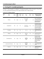
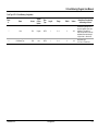
Form A6149 Part Number D301193X012 October 2013 V-Cone® Metering Program (for the ROC800-Series) User Manual Remote Automation Solutions V-Cone Metering Program User Manual Revision Tracking Sheet October 2013 This manual may be revised periodically to incorporate new or updated information. The revision date of each page appears at the bottom of the page opposite the page number. A change in revision date to any page also changes the date of the manual that appears on the front cover. Listed below is the revision date of each page (if applicable): Page All All All ii, 1, 5, 6 Initial Issue ii Revision Oct-13 May-12 Oct-11 Apr-04 Sep-03 Revised Oct-13 V-Cone Metering Program User Manual Contents Chapter 1 – Introduction 1-1 1.1 Scope and Organization .............................................................................................................. 1-1 1.2 Product Overview ........................................................................................................................ 1-1 1.3 Program Requirements ............................................................................................................... 1-2 1.3.1 License Keys .................................................................................................................. 1-4 Chapter 2 – Installation 2.1 Installing the License Key............................................................................................................ 2-5 2.1.1 2.2 2-5 Verifying the License Key Installation ............................................................................ 2-6 Downloading the V-Cone Program ............................................................................................. 2-7 Chapter 3 – Configuration 3-1 3.1 V-Cone Configuration Screen ..................................................................................................... 3-2 3.2 Station Setup ............................................................................................................................... 3-4 3.3 Orifice Meter Setup ..................................................................................................................... 3-4 3.4 Orifice Values .............................................................................................................................. 3-6 3.5 Saving the Configuration ............................................................................................................. 3-7 Chapter 4 – Reference 4.1 Revised Oct-13 4-1 Point Type 61/71: V-Cone Metering Configuration ..................................................................... 4-2 Contents iii V-Cone Metering Program User Manual [This page is intentionally left blank.] iv Revised Oct-13 V-Cone Metering Program User Manual Chapter 1 – Introduction This chapter describes the structure of this manual and presents an overview of the V-Cone® Metering program for the ROC800-Series Remote Operations Controller (ROC800). 1.1 Scope and Organization This document serves as the user manual for the V-Cone Metering user program, which is intended for use in ROC800. This manual describes how to download and configure the V-Cone Metering user program (referred to as the “V-Cone program” or “the program” throughout the rest of this manual). You access and configure the program using ROCLINK 800 Configuration Software (version 2.00 or greater) loaded on a personal computer (PC) running Microsoft® Windows® 2000 (with Service Pack 2), Microsoft Windows XP, Microsoft Windows Vista™, or Microsoft Windows 7. The sections in this manual provide information in a sequence appropriate for first-time users. Once you become familiar with the procedures and the software running in a ROC800, the manual becomes a reference tool. This manual has the following major sections: Section 1 – Introduction Section 2 – Installation Section 3 – Configuration Section 4 – Reference This manual assumes that you are familiar with the ROC800 units and their configuration. For more information, refer to the following manuals: 1.2 ROC800-Series Remote Operations Controller Instruction Manual (Form A6175). ROCLINK 800 Configuration Software User Manual (for ROC800Series) (Form A6218). Product Overview The V-Cone program allows a ROC800 to calculate a corrected volumetric flow rate at a specified base pressure and temperature for a McCrometer V-Cone or Wafer-Cone flowmeter. The V-Cone or WaferCone flowmeter is very similar to an orifice plate calculation, uses many of the same configuration parameters, and produces many of the same calculated values. For this reason, the user program makes use of existing orifice meter run points already provided by the ROC800 firmware. In addition to the standard orifice point parameters, the ROC800 also calculates an actual volumetric flow rate, a fluid velocity, a thermal expansion factor, and the percent pressure loss in accordance with the Revised Oct-13 Installation 1-1 V-Cone Metering Program User Manual McCrometer specification McCrometer Flow Calculations for the V-Cone Flowmeter, October 2002. As part of the V-Cone program point configuration, you assign the VCone or the Wafer-Cone calculation to an orifice meter point. When the calculation is assigned, the standard AGA3 calculation is bypassed and the McCrometer calculation is performed instead. All standard orifice parameters, as well as the additional V-Cone program parameters, are available for assignment to Modbus registers, PID control loops, historical archiving, and FST and DS800 database functions. 1.3 Program Requirements The V-Cone program version 1.11 is compatible with ROC800-Series 2 firmware version 3.30 (or greater), ROC800-Series 1 firmware version 2.16 (or greater), ROC800L firmware version 1.20 (or greater), and with version 2.00 (or greater) of ROCLINK 800 configuration software. The program requires you to install an AGA 3/7/8 hardware-based license key to enable the calculations, and a V-Cone license key to enable the user program. Notes: Two versions of the program are included. Installation and operation are identical between the two programs, but they use different point type locations, different display numbers. V-Cone.61.tar uses point types 61 and uses display 61. V-Cone.71.tar uses point types 71 and uses display 71. Install the program version that avoids point type conflicts with currently installed programs. The installation process and functionality is the same for all versions of the V-Cone program. Program specifics include: File Name V-Cone.61.tar V-Cone.71.tar Target Unit/ Version ROC800Series 2 v. 3.30 ROC800Series 1 v. 2.16 ROC800Series 2 v. 3.30 User Defined Point (UDP) Flash Used (in bytes) SRAM Used (in bytes) DRAM Used (in bytes) ROCLINK 800 Version Display Number 61 16151 408 73728 2.00 61 71 16151 408 73728 2.00 71 ROC800Series 1 v. 2.16 1-2 Installation Revised Oct-13 V-Cone Metering Program User Manual For information on viewing the memory allocation of user programs, refer to Section 7.7 of the ROCLINK 800 Configuration Software User Manual (for ROC800-Series) (Form A6218). Revised Oct-13 Installation 1-3 V-Cone Metering Program User Manual 1.3.1 License Keys License keys, when matched with valid license codes, grant access to applications such as the V-Cone program. An AGA3/7/8 license key must be present to provide the required number of meter runs, and a separate license key is also required to enable the V-Cone user program. The term “license key” refers to the physical piece of hardware that can contain up to seven different licenses (refer to Figure 1–1). Each ROC800 can have none, one, or two license keys installed. If you remove a license key after enabling an application, the firmware disables the task from running. This prevents unauthorized execution of protected applications in a ROC800. J1 U1 DOC0422A Figure 1-1. License Key 1-4 Installation Revised Oct-13 V-Cone Metering Program User Manual Chapter 2 – Installation This section provides instructions for installing the V-Cone program into the ROC800. Read Section 1.3 of this manual for program requirements. Notes: 2.1 The computer running ROCLINK 800 must be connected to the Local Operator Interface (LOI) port before you begin the download. The program and license key can be installed in any order. The manual shows the installation of the license key first. The installation process and functionality is the same for all versions of the V-Cone program. Installing the License Key If you order the V-Cone program for a new ROC800, your ROC800 is delivered with the license key installed. Go to Section 2.2. If you order the program for an existing ROC800, you must install the license key yourself. Caution Failure to exercise proper electrostatic discharge precautions, such as wearing a grounded wrist strap may reset the processor or damage electronic components, resulting in interrupted operations. When working on units located in a hazardous area (where explosive gases may be present), make sure the area is in a non-hazardous state before performing these procedures. Performing these procedures in a hazardous area could result in personal injury or property damage. To install a license key: 1. Remove power from the ROC800. 2. Remove the wire channel cover. 3. Unscrew the screws from the Central Processing Unit (CPU) faceplate. 4. Remove the CPU faceplate. 5. Place the license key in the appropriate terminal slot (P4 or P6) in the CPU. Incorrect Correct DOC0423A Figure 2-1. License Key Installation Note: When using a single license key, install it in slot P4. Revised Oct-13 Installation 2-5 V-Cone Metering Program User Manual 6. Press the license key into the terminal until it is firmly seated (refer to Figure 2–1). 7. Replace the CPU faceplate. 8. Replace the screws on the CPU faceplate. 9. Replace the wire channel cover. 10. Restore power to the ROC800. 2.1.1 Verifying the License Key Installation After you install the license key, you can verify whether the ROC800 recognizes the key. From the ROCLINK 800 screen, select Utilities > License Key Administrator. The License Key Administrator screen displays: Figure 2-2. License Key Administrator V-Cone appears in the Application Name column. [For further information on the License Key Administrator screen, refer to Section 2.4 of the ROCLINK 800 Configuration Software User Manual (for ROC800Series) (Form A6218).] After you verify that the license key is correctly installed and recognized, proceed to Section 2.2 to download the user programs. 2-6 Installation Revised Oct-13 V-Cone Metering Program User Manual 2.2 Downloading the V-Cone Program This section provides instructions for installing the V-Cone program into the Flash memory on the ROC800. Note: Connect a PC to the ROC’s LOI port before starting the download. To download the user program: 1. Select any empty program number (in this case, number 1) into which to download the program: Figure 2-3. User Program Administrator 2. Click Browse in the Download User Program File frame. The Select User Program File screen displays (see Figure 2–4). 3. Select the path and user program file to download from the CD-ROM. (Program files are typically located in the Program Files folder on the CD-ROM.) As Figure 2–4 shows, the screen lists all valid user program files with the .TAR extension: Revised Oct-13 Installation 2-7 V-Cone Metering Program User Manual Figure 2-4. Select User Program File 11. Click Open to select the program file. The User Program Administrator screen displays. As shown in Figure 2–5, note that the Download User Program File frame identifies the selected program and that the Download & Start button is active: Figure 2-5. User Program Administrator 12. Click Download & Start to begin loading the selected program. The following message displays: 2-8 Installation Revised Oct-13 V-Cone Metering Program User Manual Figure 2-6. Confirm Download 13. Click Yes to begin the download. The following message displays when the download completes: Figure 2-7. ROCLINK 800 Download Confirmation 14. Click OK. The User Program Administrator screen displays (see Figure 2-8). Note that: The Device User Program Environment frame reflects the use of system memory. The User Programs Installed in Device frame identifies the installed program(s). The Status field indicates the program is loaded and running. Revised Oct-13 Installation 2-9 V-Cone Metering Program User Manual Figure 2-8. User Program Administrator 15. Proceed to Section 3 to configure the programs. 2-10 Installation Revised Oct-13 V-Cone Metering Program User Manual Chapter 3 – Configuration After you have loaded the V-Cone program, you configure it using ROCLINK 800 software. Most of the configuration for the V-Cone meter is done through the standard orifice meter setup screen and the station setup screen for the station to which the orifice meter belongs. For more information, refer to ROCLINK 800 Configuration Software User Manual (for ROC800-Series) (Form A6218). To do this, you use one program-specific screen (V-Cone Configuration) and two standard ROCLINK 800 screens (Orifice Meter Setup and Station Setup): Use the V-Cone Configuration screen to enable, select the McCrometer type along with the corresponding flow coefficient, and assign the V-Cone calculation for a specific meter run. Use the Station Setup screen to configure parameters common to multiple meter runs. Use the Orifice Meter Setup screen to configure parameters for a single meter run for use with the V-Cone program. Use the Orifice Values screen to view values calculated by the V-Cone program. Figure 3-1. ROCLINK 800 screen Revised Oct-13 Configuration 3-1 V-Cone Metering Program User Manual 3.1 V-Cone Configuration Screen Use the V-Cone configuration screen to assign the V-Cone meter to an existing orifice meter run and to enter the flow coefficient. You can also view the actual volumetric flow rate per second, the thermal expansion coefficient, the fluid velocity, and the percent pressure loss. To access this screen: 1. From the Directory Tree, select User Program > Program #1, V-Cone. 2. Select Display #61/71, V-Cone Configuration. 3. Double-click #1. The V-Cone Configuration screen displays: Figure 3-2. V-Cone Configuration Screen 4. Review the values in the following fields: 3-2 Field Description Point Number Indicates the iteration of the program you want to define. You can assign each iteration of the program (up to 12) to individual meter runs. Click ▼ to display additional iterations. Configuration Revised Oct-13 V-Cone Metering Program User Manual Field Description V-Cone Tag This read-only field shows the meter tag for the selected meter. The meter tag is defined in Meter>Setup. End Element Type Specifies the end element type of the selected meter. Valid Selections are V-Cone and WaferCone. Associated Orifice Run Sets the orifice meter used in V-Cone calculations for the selected point number. Either the Orifice Meter Run Configuration or Orifice Meter Run Values point type can be selected and any valid logical or parameter number. Note: The selected orifice meter point is automatically assigned a “User Defined Device” meter type and the user program will be in control of calculating all values except compressibility and density. Flow Coefficient Sets a user-defined value for calculations. This value is obtained from the V-Cone sizing and calibration report. Units This read-only field displays the units of measurement for this V-Cone point. Valid values are US or Metric. Note: The Units selection is made under Meter>Setup>Station for the station to which the associated orifice meter run belongs. Fluid Velocity This read-only field displays the velocity of the fluid through the V-Cone. Values are in feet/second or meters/second. Actual Volume Flow Rate This read-only field displays the volumetric flow rate at the flowing temperature and pressure. Values are in ft3/second or m3/second. Percent Pressure Loss This read-only field displays the permanent pressure loss at the V-Cone expressed as a percentage of the differential pressure. Thermal Expansion Factor This read-only field displays the correction for the expansion of the cone and pipe materials, due to differences between operating temperature and calibration temperature. 5. Click Apply to save any changes you have made to this screen. 6. Proceed to Section 3.2 to configure the Orifice/Station configuration. Revised Oct-13 Configuration 3-3 V-Cone Metering Program User Manual 3.2 Station Setup The Station Setup screen is accessed via Meter > Setup > Station. This screen allows for configuration of attributes that are common to multiple meter runs. General items such as the base pressure, base temperature, unit selection and gas quality data are configured here. On the general tab, several station values are displayed which represent the summation of all the meter runs in the station. For more information, refer to ROCLINK 800 Configuration Software User Manual (for ROC800-Series) (Form A6218). Figure 3-3. Station Setup – Advanced Tab Review the configuration on this screen, and click Apply to save any changes you have made. Proceed to Section 3.3 to configure the Meter Setup screen. 3.3 Orifice Meter Setup The Orifice Meter Setup screen is accessed via Meter > Setup > Orifice Meter. This screen allows for configuration of attributes of a single orifice meter. The Meter Type selection on the Orifice Meter Setup screen is automatically set to “User Defined Device” by the V-Cone user program when the orifice meter point for the selected meter run is selected as the associated meter run in the V-Cone program. This has the effect of bypassing the standard AGA3 calculation and allows the V-Cone program to write the results of the V-Cone or Wafer-Cone calculation to the orifice meter point type. The following parameters have different meanings for the V-Cone metering user program. 3-4 Configuration Revised Oct-13 V-Cone Metering Program User Manual Orifice Diameter – Represents the diameter of the V-Cone or Wafer-Cone Values are in inches or mm. Figure 3-4. Orifice Meter Setup – General Tab Orifice Material – Represents the type of material of which the VCone or Wafer-Cone is constructed. Valid vales are Stainless Steel, Monel, or Carbon Steel. Ref Temp – Represents the temperature at which the V-Cone or Wafer-Cone diameter was measured. Values are in Deg F or Deg C. Figure 3-5. Orifice Meter Setup – Advanced Tab Revised Oct-13 Configuration 3-5 V-Cone Metering Program User Manual Review the configuration on this screen, and click Apply to save any changes you have made. Proceed to Section 3.3 to view orifice values. 3.4 Orifice Values Parameters displayed on the Meter > Values > Orifice Meter screen represent values calculated by the V-Cone program for orifice meters associated with a V-Cone point number. The Orifice Diameter value on the Factors tab represents the V-Cone diameter in inches or mm. Values are calculated per the McCrometer V-Cone specification. Figure 3-6 Orifice Meter Values Proceed to Section 3.5 to save your configuration. 3-6 Configuration Revised Oct-13 V-Cone Metering Program User Manual 3.5 Saving the Configuration Whenever you modify or change the configuration, it is a good practice to save the final configuration to memory. To save the configuration: 1. Select ROC > Flags. The Flags screen displays: Figure 3-7 Flags screen 2. Click Save Configuration. A verification message displays: Figure 3-8 Perform screen 3. Click Yes to begin the save process. The Flash Write Status field on the Flags screen displays In Progress. When the process ends, the Flash Write Status field on the Flags screen displays Completed (see Figure 3-9). Revised Oct-13 Configuration 3-7 V-Cone Metering Program User Manual Figure 3-9 Flags screen 4. Click Update on the Flags screen. This completes the process of saving your new configuration. Note: For archive purposes, you should also save this configuration to your PC’s hard drive or a removable media (such as a diskette or a flash drive) using the File > Save Configuration option on the ROCLINK 800 menu bar. 3-8 Configuration Revised Oct-13 V-Cone Metering Program User Manual Chapter 4 – Reference This section provides tables of information on the user-defined point types used by the V-Cone program. Revised Oct-13 Point Type 61/71 (V-Cone Metering Configuration) Reference 4-1 V-Cone Metering Program User Manual 4.1 Point Type 61/71: V-Cone Metering Configuration Point type 61/71 contains the parameters for configuring the V-Cone program and contains the calculation results specific to V-Cone or WaferCone. Up to 12 logical points of this point type will exist, equal to the number of AGA3/7/8 meter runs licensed. Point Type 61/71: V-Cone Metering Configuration Parm # 0 Name Point Tag Id. Access R/O System or User Update Program Data Type AC Length Range 10 0x20 → 0x7E for each ASCII character Default ““ Version Description of functionality and meaning of values 1.00 Identification name for the V-Cone meter run. The tag is assigned to the associated orifice meter run and the value is copied to the V-Cone point type 61. Values must be printable ASCII characters. 1 Associated Meter Run R/W User TLP 3 113 or 114, 0→11, Any valid parameter 0, 0, 0 1.00 The associated orifice meter run contains most of the configuration parameters and calculated values for the V-Cone meter and provides the density and compressibility values to the V-Cone calculation. 2 Flow Coefficient R/W User Float 4 >0.0 → 5.0 1.00 1.00 User entered flow coefficient, obtained from sizing and calibration reports. 3 Fluid Velocity R/O Program Float 4 Any Positive Floating Point Number 0.00 1.00 Calculated value of fluid velocity in ft3/second or m3/second. 4 Thermal Expansion Factor R/O Program Float 4 Any Positive Floating Point Number 1.00 1.00 Calculated value of thermal expansion factor. This factor corrects for the thermal expansion of the cone and pipe materials due to differences between operating temperature and calibration temperature. 5 Actual Volumetric Flow Per Second R/O Program Float 4 Any Positive Floating Point Number 0.00 1.00 The volumetric flow rate at flowing pressure and temperature in ft3/sec or m3/sec. 6 Pressure Loss R/O Program Float 4 0.0-100.0 0.00 1.00 The permanent pressure loss represented as a percentage of the differential pressure. 4-2 Configuration Revised Oct-13 V-Cone Metering Program User Manual Point Type 61/71: V-Cone Metering Configuration Parm # Name Access System or User Update Data Type Length Range Default Version Description of functionality and meaning of values 7 Units R/O Program UINT8 1 0→1 0 1.00 Indicates the engineering units for the process variables, inputs, and calculations. This selection is copied from the station to which the associated orifice meter belongs. 0 = English Units, 1 = Metric Units. 8 End Element Type R/W User UINT8 1 0→1 0 1.10 End Element Type: 0 = V-Cone, 1 = Wafer-Cone Revised Oct-13 Configuration 4-3 Headquarters: Emerson Process Management Remote Automation Solutions 6005 Rogerdale Road Houston, TX 77072 U.S.A. T +1 281 879 2699 | F +1 281 988 4445 www.EmersonProcess.com/Remote Europe: Emerson Process Management Remote Automation Solutions Unit 8, Waterfront Business Park Dudley Road, Brierly Hill Dudley UK DY5 1LX T +44 1384 487200 | F +44 1384 487258 www.EmersonProcess.com/Remote North American/Latin America: Emerson Process Management Remote Automation Solutions 6005 Rogerdale Road Houston TX USA 77072 T +1 281 879 2699 | F +1 281 988 4445 www.EmersonProcess.com/Remote Middle East/Africa: Emerson Process Management Remote Automation Solutions Emerson FZE P.O. Box 17033 Jebel Ali Free Zone – South 2 Dubai U.A.E. T +971 4 8118100 | F +971 4 8865465 www.EmersonProcess.com/Remote Asia-Pacific: Emerson Process Management Remote Automation Solutions 1 Pandan Crescent Singapore 128461 T +65 6777 8211| F +65 6777 0947 www.EmersonProcess.com/Remote Remote Automation Solutions © 2003-2013 Remote Automation Solutions, a business unit of Emerson Process Management. All rights reserved. Remote Automation Solutions, a business unit of Emerson Process Management, shall not be liable for technical or editorial errors in this manual or omissions from this manual. REMOTE AUTOMATION SOLUTIONS MAKES NO WARRANTIES, EXPRESSED OR IMPLIED, INCLUDING THE IMPLIED WARRANTIES OF MERCHANTABILITY AND FITNESS FOR A PARTICULAR PURPOSE WITH RESPECT TO THIS MANUAL AND, IN NO EVENT SHALL REMOTE AUTOMATION SOLUTIONS BE LIABLE FOR ANY INCIDENTAL, PUNITIVE, SPECIAL OR CONSEQUENTIAL DAMAGES INCLUDING, BUT NOT LIMITED TO, LOSS OF PRODUCTION, LOSS OF PROFITS, LOSS OF REVENUE OR USE AND COSTS INCURRED INCLUDING WITHOUT LIMITATION FOR CAPITAL, FUEL AND POWER, AND CLAIMS OF THIRD PARTIES. Bristol, Inc., Bristol Canada, BBI SA de CV and Emerson Process Management Ltd, Remote Automation Solutions (UK), are wholly owned subsidiaries of Emerson Electric Co. doing business as Remote Automation Solutions, a business unit of Emerson Process Management. FloBoss, ROCLINK, Bristol, Bristol Babcock, ControlWave, TeleFlow, Helicoid, OpenEnterprise, and METCO are trademarks of Remote Automation Solutions. AMS, PlantWeb and the PlantWeb logo are marks of Emerson Electric Co. The Emerson logo is a trademark and service mark of the Emerson Electric Co. All other marks are property of their respective owners. The contents of this publication are presented for informational purposes only. While every effort has been made to ensure informational accuracy, they are not to be construed as warranties or guarantees, express or implied, regarding the products or services described herein or their use or applicability. Remote Automation Solutions reserves the right to modify or improve the designs or specifications of such products at any time without notice. All sales are governed by Remote Automation Solutions’ terms and conditions which are available upon request. Remote Automation Solutions does not assume responsibility for the selection, use or maintenance of any product. Responsibility for proper selection, use and maintenance of any Remote Automation Solutions product remains solely with the purchaser and end-user.