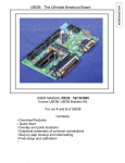
1
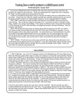
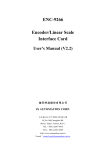
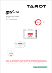
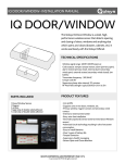
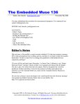
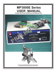
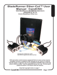
SETTING and TESTING INPUTS - HOMES
The bulk of MACH3 and the Hardware has to do with Inputs and Outputs (I/O). In the BladeRunner AIO system
I/O takes several forms. Ultimately an INPUT is a signal coming INTO MACH3 from an external source as a logic
level (either Active High or Active Low) MACH is setup to “watch” certain Ports and Pins (input points) and then
using a term called “mapping” it assigns an INPUT to an ACTION. The BladeRunner is unique in that it has
double the number of normal inputs to a single Parallel (printer/LPT) port so you have more than the normal 5
inputs to work with. This is essential when using the THC function in MACH because it alone needs 3 dedicated
inputs.
It is important to understand how the input Port Expansion works and how the mappings are used.
The UBOB III is the hardware I/O part of the BladeRunner. It takes outside inputs from the Table I/O card to
sense physical switches and sets up the “sharing” of the inputs. There are two PORTS defined in the setup.
PORT1 and PORT8. PORT 8 is the shared port to PORT1. The physical inputs are individual and each one is
opto-isolated and noise filtered. The circuit in the UBOB III takes all of the individual inputs and puts them on
TWO BANKS of signals.....4 on each bank (E-STOP is not shared). A special pulse is sent from MACH to tell the
hardware which BANK to read. This happens thousands of times per second in a process called “multiplexing”.
MACH alternately reads all of the inputs from BANK A (PORT 1) and then from BANK B (PORT 8). It is an
effective way to increase the number of input signals without having to add more physical inputs at the computer.
There are two things to keep in mind:
The shared inputs do not work when MACH is in RESET because all outputs are off and that includes the
special pulse from MACH to switch back and forth between the two BANKS of inputs.
The shared input process is controlled through a special DRIVER (plug-in) for the UBOBIII. It has to be
installed and enabled and set correctly for the shared inputs to work.
(versions of MACH3 before 3.41.020 DO NOT SUPPORT SHARED INPUTS even if the UBOBIII driver is loaded.
UBOB driver is ccc_UBOB.dll. It is added during an auto-install from the CD or the BladeRunnerAIOUBOB3-Install file.
The DTHC critical signals of THC ON (Arc OK), THC UP and THC DOWN and the Z home for the IHS (Initial
Height Sensing aka “Touch-off”) are REQUIRED for a Plasma setup. Other inputs are not required but highly
recommended to help in the cut process.
When you load the BladeRunnerAIO-UBOB3-Install file earlier in this manual it loads the right Drivers (plug-ins)
enables them and sets their parameters. It also provides a default configuration for all of the INPUTS and
OUTPUTS that are common on the BladeRunner. The following screens show what the default settings will look
like. There may be differences in settings for inputs NOT ENABLED. Do not worry. A disabled input is ignored by
MACH3. Only the pins that are enabled count.
THE DEFAULT SETUP
1, XYZ&A Homes are enabled and set to the correct port/pin pairs
2. All LIMITS are disabled (see setting up LIMITS for details)
3 The THC INPUTS are all enabled and setup...even on a Router Profile since those
inputs can be re-purposed and used for other functions if desired.
4. The E-STOP cannot be disabled and the Active Low setting is critical (RED X default)
CandCNC
Page 70
BladeRunner
Hardware
G
SETTING and TESTING INPUTS - HOMES
Each axis as a ++ and – which are the FAR and NEAR LIMITS. Each axis has a HOME
Each axis has an Enabled Column. Do not use Emulated ON (Red X for normal setups)
BladeRunner
Hardware
G
DO NOT USE THIS BUTTON!
The BladeRunner is unique in that it has two input PORTS (1 & 8). The pins are “shared”
so that PORT 1 Pin 11 is shared with PORT 8 PIN 11. That offers doubel the normal inputs
Note: A home is enabled by default. This may need to be changed if you do not software slave
A to another axis with a Home. See the setup of Homes & Limits section for details
E-Stop Cannot be disabled. The Active Low value is important. Note THC related signals are
on PORT 8. THC ON is the same as ARC OK.
CandCNC
Page 71
THE CHARGE PUMP
THE CHARGE PUMP
The Charge Pump (CP) is an important safety signal in MACH and used by the BladeRunner. It is a ‘Keep
Alive” signal that is a waveform (approx 12 KHZ) and is generated by MACH and controlled by MACH and
the CandCNC drivers. If for any reason the power to the control system is turned on before the PC is
powered up it is possible that as the PC “boots” the parallel port can have signal changes (during POST)
that would might cause an output to go active.
Stepper motors require very specific signals to move making them inherently immune to random port
signals, The circuits in the BladeRunner do not allow any signal to pass to any of the drives unless MACH
is fully started and is functional and the operator has brought the system out of reset. NO CP, NO
OUTPUTS!
HOW IT WORKS:
MACH is programmed to turn on the CP only when MACH is loaded and has control of the PC and the
parallel port and MACH is out of RESET. While MACH controls the output signals through internal logic
there are hardware functions that act as a second level of safety. In the UBOB III based system the CP
signal MUST be present (not just a logic level) on the CP line from the PC or the internal buffers will be
disabled. No outputs will function. Without CP no Step signal will be sent to any motor drive (No
MOTION). Without CP no relay will fire.
If you start MACH and the BladeRunner and you get no motion the first thing is to check the CP LED on
the side of the BladeRunner. It detects and turns on the buffer circuits in the BladeRunner.
CandCNC
Page 72
BladeRunner
Hardware
G
TABLE I/O CARD LOCATION
CHECKING INPUT SIGNALS:
The following sections detail how to use the hardware interface to use Inputs and
Outputs. Please review the section on the physical location of the internal cards and
then the section on the Table I/O card (where Homes and Limits and other Inputs are
connected. There are sections on using the E-STOP (either software or hardware or
both) Setting up HOMES and testing and optional LIMITS. Even if you do not plan to
use the XY or A homes it is important to at least test each input.
TABLE I/O MODULE LOCATION INSIDE BLADERUNNER AIO ESPII CASE
To access Inputs turn off power and remove fron cover. Locate Table I/O
Card and use detialed pages in this setion to make INPUT connections
1
QUAD 6
RELAY
T10
14 PLUG
J2
1
ALT8
K
ALT7
D15
ALT6
ARC OK
K
K
UP
C11
ARC OK
D16
UP
C6
J14
C8
J13
ALT5
25
10
R5
D20
Q6
R8 R4 K
C14
C1
D18
T3
DOWN
K
K
ALT4
C5
J10
C4
J8
C3
J12
ALT3
DOWN
C9
J9
LIMITS
AHome
D8
LIMITS
T2
T19
D7
D6
T17
ZHome
AHome
T5
K3
D5
T15
D4
C2
J7
ALT2
D21 K
R7
2 3
J22
1
K4
D3
K3
R1
D10
K4
T13
Q5
C12
R3
DANGER! DANGER!
YHome
ZHome
13
C13
K D11
J5
J18
K4
K3 R2
COM
J4
K4
Xhome
J11
EPO
NO
NO Com2
T21
T20
D2
YHome
Xhome
ALT1
EPO
C&CNC REV 1
TABLEI/O-16
INSIDE TOP VIEW
TABLE I/O or TABLE I/O II CARD
This area open fo
DTHC or ISS-02
Expansion
CARDS
UBOB III Universal Breakout Board
BLADERUNNER UBOB MODULE DETAILS
CandCNC
Page 73
BladeRunner
Hardware
G
SETTING and TESTING INPUTS - HOMES
Setting up HOMES.
Homes are used for establishing a known POSITION, Most often to define the
TABLE ZERO locations and be able to return to the same fixed spot. Much like the
address on your house versus the location of you RV at any given time. If you
establish a TABLE 0 and do all of your cutting in reference to the TABLE ZERO than
you can always re-establish your cut at anytime even after a power failure and ESTOP event that can cause the loss of position.
TESTING HOMES at the TABLE I/O.
If you have not yet mounted or wired your HOME switches yet, it is easy to test to
make sure of there operation:
1. UNPLUG THE AUXILLARY AC CORD THAT PROVIDES POWER FOR THE AC
SOCKETS BEFORE YOU RUN ANY TESTS! You will need to power up the
BladeRunner and the DC supply to run the INPUT tests but there is no AC high
voltage in the top of the unit UNLESS YOU HAVE THE AUX AC CORD PLUGGED
IN.
2. Open the BladeRunner up (remove the cover and place it gently off to one side
leaving the cables to the Front Panel plugged in. Expose the TABLE I/O in the top of
the case as shown in the illustration on page_73 Note the input terminal pairs are
side by side in two rows.
3. Power up the BladeRunner AIO with and turn on the DC (Front Panel). You do
not need the motors plugged in, but if they are it is okay. MACH will not come out of
RESET if the DC power is off. Inputs do not work right if MACH is in RESET
4. Make sure MACH3 is loaded and the BladeRunner Profile is selected. Open
the DIAGNOSTICS PAGE for the test
5. To test the inputs use a small screwdriver or metal object to short across a pair
of inputs. Start with X Home and go down through A home.
6. Note on the TABLE I/O Card there are small LED’s next to each pair. When
you short across and pair you should see the associated LED turn on. That
indicates the circuit is complete between the Input on the Table I/O and the UBOBIII.
It also confirms the 25 pin cable is working.
CandCNC
Page 75
BladeRunner
Hardware
G
SETTING and TESTING INPUTS - HOMES
MAKE SURE THE AUX AC INPUT CORD IS DISCONNECTED FROM THE WALL
SOCKET BEFORE YOU RUN ANY TESTS
DANGER ZONE
WHEN AUX AC
CORD IS
PLUGGED IN
CONNECTED TO
TABLE I/O HEADER
ON UBOB III CARD
TO TEST:
SHORT
ACROSS
INPUT PAIRs
Example of testing X HOME input and indications on the
DIAGNOSTICS SCREEN. Test each input at a time and match up
the INPUT STATUS. The RAW PORT BITS shows the signal AT
THE PORT 1 input on the PC as MACH sees it. NOTE: You cannot
test the LIMIT input. The AUX 0 is NOT and input for the
BladeRunner.
Flashing INPUT
on RAW PORT
INPUT BITS
4 5
6 7 8
Checking the INPUTS
RAW PORT INPUT BITS
BIT 4 = A home/THC DOWN
BIT 5 = Z home/THC UP
BIT 6 = Y home/ARC OKAY
BIT 7 = E-STOP(EPO)
BIT 8 = X home/LIMITS
CandCNC
NORMAL INDICATIONS
With PORT1 unplugged from BladeRunner: All Bits (4 - 8} should
be ON STEADY
When MACH is out of reset then you should see the RAW PORT
BITS SHOWN ABOVE. Flashing inputs indicate activity on that
input (E-STOP MUST BE OFF - STEADY (dark))
Page 76
BladeRunner
Hardware
G
SETTING and TESTING INPUTS - HOMES
EXAMPLE of HOME SWITCH
MicroSwitch Type switch with roller
lever actuator. Switch has .250 quik
connects and a NO and NC set of
contacts. Mouting in this case is drilled
and tapped AL block with High Strength
3M double-sided tape holding it to the
table frame Switch trips on bottom of
gantry frame but allows it to roll past if
needed.
Mount your HOME Switches so they define the X and Y zeros on your table. Mount some clips or
brackets (stops) on the cutting surface or edges to let you index a sheet of material in relation to the
table zero. Even if the STOPS are not exactly at table zero you can deal with the offsets in the CAM
layout. Having alignment stops on your table let you accurately remove then re-load a piece of
material. Having a defined table 0, 0 that can be referenced to makes the recovery of a loss of
absolute position easy to recover from. We have provided enough inputs to allow for up to 4
Homes.
The Z home setup is covered on the next page and depends on the type Floating Torch Holder you
are using.
The BladeRunner AIO enclosure is furnished with 2 access holes for routing switch wires into the box
for connection to the tabs on the TABLE I/O card. The holes are filled with two rubber knock-out
plugs that are easily removed. HOME switch wires carry very small amounts of current (< 15ma) and
low voltage (3 -5 volts DC) so the wire size is not critical. It is recommended it be stranded for
flexibility on any moving part of the table and for longer runs twisted pair(s) are recommended. Wire
from 24Ga to 18Ga works best. The smaller the conductor the more wire pairs will fit through the
access holes. Use the correct sized Crimp-On connector for the size wire you use.
Switch Wire Access
Plugs on End of
BladeRUnner AIO
CandCNC
Page 77
BladeRunner
Hardware
G
Home Switch Connections: At least one Home (Z) is required if you are
using the BladeRunner Dragon-Cut for plasma tables. It is recommended
you mount and connect up HOMES for the X & Y but it is not required.
Z AXIS “Touch Off” SWITCH
Z HOME
WHAT IS A FLOATING TORCH
HOLDER and WHY DO I NEED ONE?
Example of a Z with the Floating Torch Holder for
doing the IHS for Plasma cutting.
The Floating Torch holder is a torch
holder mounted on a separate slide
from the Z axis and allows the torch to
move UP and DOWN independent of
the Z motion. In operation it uses the
end of the torch (torch tip) as a “Probe”
to find the Top-of-Material. Because
metal tends to warp and the slats may
not be perfectly level, the Z zero
changes (top of the material) as you
move around the table surface. The
DTHCII will track the rise and fall of the
material as it cuts to hold a constant arc
gap, BUT the absolute value of Z as
displayed by the Z DRO is based on the
LAST REFERENCE DONE. (Where it
started) Each pierce needs to be done
at exactly the right height above the
material so a method if Initial Height
Sensing (IHS) is needed. The Floating
Torch holder lets the Torch be the
sensing probe for the IHS. It is a
mechanical way to do the probe and is
more reliable than ohmic or capacitive
sensing. Using a Z homing sequence
generated by the G-Code (from
SheetCAM) the Z is lowered until the tip
of the torch touches the metal and the
floating mount allows the torch to be
pushed UP and that trisp the swtich.
Z AXIS FLOATING HEAD
SWITCH. Close up of
switch connections. Use
Normally Open Pair.
(Precision Plasma HD
Gantry and Z)
CONNECTED TO Z
HOME in BLADERUNNER
on the TABLE I/O
CandCNC
Page 78
BladeRunner
Hardware
G
SETTING and TESTING INPUTS - HOMES
BladeRunner
Hardware
G
Using an Optional Salve
Side Home Switch;
Typical rectangular
table setup
It is advantageous to use a
HOME on the slaved axis
(in this case A). There is an
input for an A HOME. If you
set your inputs to have an A
HOME in INPUT SIGNALS
then slave the A axis the
gantry will move towards
the switches and stop the
motor on the first one to
make contact. The other
axis will continue to run unitl
it contacts it;s swtich . If the
two sides have gotten out of
sync the XY REF will let the
gantry “Auto-square” itself.
Y axis
4 motor setup (dual drive
on the gantry)
X Home
SWITCH
If you make the bracket on
one side or the other
adjustable you and fine
tune the position and
square the gantry with the
table.
CandCNC
X, Y Homes
A Home
SWITCH
Z axis w/ torch holder
Z HOME
Y Home
SWITCH
If you elect NOT to use a
slave axis HOME (in case
you need the input for
something else). You
must still enable A home
in the MACH Profile but
map the A home to the
same Port and PIN as the
Master Home (Y in this
example)
GANTRY
X axis
0, 0
If you stand here to run the machine
then 0, 0 is lower left corner from your
location. X is cross axis (short axis)
Make this
Switch Bracket
Adjustable
Page 79
SETTING and TESTING INPUTS - HOMES
G
Each HOME Switch in the system has an associated set of parameters to define
how it is used.
To access the Configuration Menu open the CONFIG/Homing&Limits window
shown below. Most of the defaults will be correct. The HOME NEG setting tells
MACH which way to move to find a home switch. After you setup your home
switches you should test each one and setup the seek direction.
1. Make sure the HOME switch shows up in the Diagnostics Window when you
manually activate the switch. On the Z home for a plasma setup using the floating
Torch holder, manually raise the torch by hand and test the switch.
2. Do one axis at a time. In the Program Run and the Diagnostics Tab you will find
a REF button next to each axis DRO. Move (jog) each axis out several inches
away from it’s home switch. Click the REF button on the X axis and if it starts to
move AWAY from the HOME Switch, stop the motion and open the Home & Limits
window and click the Home NEG indicator for that axis. Each time you click it will
change the setting from a Green Check to a RED X and back. Set it to the
opposite value and click OK. Re-Test the REF on the axis you changed and make
sure it moves to it’s Home Switch.
3. Test and set each axis Home that you have
When Homing, the Z axis on a Plasma setup should move down to the material. It
will move until it trips the Z home switch then stop, IT WILL NOT
AUTOMATICALLY PICK UP THE Z above the material.
CandCNC
Page 80
BladeRunner
Hardware
SETTING HOME SWITCH “SEEK” DIRECTION.
HOME & LIMIT WIRING
BladeRunner
Hardware
G
Home and limit switch hook ups
Typical connections for Homes and Limits
START of
STRING
NO
COM
NC
NO
COM
NC
NO
COM
NC
NO
NC
All of the inputs are opto isolated and map to a
specific pin on the parallel port(s). In reality you
can use any input for any signal. Inputs are not
fast enough for Encoder feedback faster than a
few pulses per second. The inputs use a “floating”
ground (+12 return). If you need more inputs than
the 8 (9 with EPO) then a PORT 2 card can be
hooked to the UBOB and the added Aux and
COM
Normally closed contacts
For far limits. Wired in series
END of
STRING
JUMPER EPO to be able to
bring MACH out of RESET
AUX0
DOWN
T2
T3
UP
T4
EPO
J1
C14
T11
ARC OK
D15
AUX1
D3
R1
J13
AUX2
K3
J12
K4
R2
J18
J5
AUX3
C11
NO Com2
Com1
48
NO
J4
BHOME
C10
K5
K3
K4
DANGER!
DANGER!
J7
J8
AUX4
J11
Xhome
D2
C1
10
13
25
C&CNC
47 TABLE I/O
REV 6
J6
49
K4
C13C12
QUAD RELAY
J10
J33
K3
D9
6
1
J9
T13
YHome
ZHome
AHome
LIMITS
DWN
AUX0
UP
14
1
T20
T21
T15
T10
T17
T12
C2
ARC OK
LIMITS
AHome
T19
50
T14
ZHome
C9
T16
C4
C3
T18
YHome
T6
Xhome
T5
52
T7
C5
T8
C8
PLUG
C7
C6
J2
T9
QUAD RELAY HEADER
is for an optional quad relay card
and adds 4 more relays to the outputs.
CandCNC
Page 81
COM
NO
NC
X
COM
NO
NC
Y
COM
NC
Z
NO
Individual Homes Wired Normally Open
BladeRunner
Hardware
G
The X Home should light up when you manually activate X Home switch. It should be off
when the switch is not active. If it is reversed (i.e. goes OFF when you activate the switch
but stays on otherwise) you will need to reverse the polarity of the switch in Ports & Pins/
Input Signals. We recommend using normally open (NO) contacts on Homes and Normally
Closed (NC) contacts on the far limits (if used).
The far limits are wired in series external to the Table I/O card and it is setup so breaking
the string at any point activates a hard limit. The hard limits are safety switches located at
points on the table to prevent the machine from going past the table travel limits. You can
have far limits (opposite the 0,0 location of the table) AND near limits (at points where the
machine would crash on the other side of the Home switches. Limits are optional and on
stepper based systems you could elect to have just hard stops since the motors can be
stalled without damage.
A NOTE ABOUT LIMITS on the BladeRunner:
A stepper motor/driver is a “torque limited system” meaning that the drives limit the amount
of torque a stepper motor can apply to a load. It does that by limiting the current on each
pulse. While most AC and DC motors will quickly exceed their ratings if presented with a
large overload, the stepper just stalls (starts slipping) and “loses steps”. Because if this
they are safe from overload and will simply stop turning. Simple mechanical stops on an
axis will keep motors from running to far and no damage to motor or drive is inflicted. It
sounds bad because the motor vibrates as it attempts to turn but no harm is done. The
motor will not overheat and the electronics will not see it as an overload unless all 4 motors
are stalled at the same time. LIMITS are more for decoration than function on a stepper
system. Some users like to have them. If that describes you then by all means install and
set them up...you will feel much better!
CandCNC
Page 82
SPECIAL MANUAL JOG INPUT
For Oxy-Fuel Cutting
SPECIAL SECTION: Hooking up a remote control for doing Oxy-Fuel cutting.
Disregard this section if you do not have an oxy-fuel setup on you table.
IF YOU DO WANT TO SETUP AN OXY_FUEL SYSTEM PLEASE NOTE THE
FOLLOWING:
1. Setup and copy your working Plasma Profile using the MACH LOADER covered
inPage 34 of this manual.
2, Make the changes listed on the next pages to THAT NEW PROFILE.
3. You can control the Z UP and DOWN manually during flame cutting using either a
set of switches OR the PC keyboard but not BOTH.
4. There may be some reconfiguration of outputs needed for oxy=fuel if you want
automated control of the Oxygen valve and/or an automatic striker.
5. The THC cannot sense the height of the tip since there is no cutting volts or current
to read. Typically oxy-fuel is done on thicker material and at much slower feedrates
than plasma so manual height operation is possible.
CandCNC
Page 83
BladeRunner
Hardware
G
SPECIAL MANUAL JOG INPUT
For Oxy-Fuel Cutting
BladeRunner
Hardware
G
If you want to use the manual UP and DoWN inputs on the Table I/O card for controlling the Z while code is running
you can use one of the swtich setups on the previous page into inputs. You must then open the COFIG in MACH
and select PORTS 7 PINS and the MILL OPTIONS TAB as shown. Check the “Allow THC UP/DOWN Control
even if not in THC Mode” Checkbox and then APPLY button. This sets up MACH so it will listen to the UP and
DOWN commands even when the THC Button is OFF in MACH. Also remember that the UP and DOWN inputs on
the Table I/O card are in parallel with the UP and DOWN signals from the DTHC so MACH will LISTEN TO
EITHER. The manual UP and DOWN is not normally used with the DTHC and the THC Button enabled. You CAN
manually control the plasma height if you turn off the THC button and have the above box checked but it is
not recommended. The speed at which plasma normally cuts and the small arc gaps involved makes the
reaction time too slow for manual Z spacing
To do the same thing using the keyboard you must setup the INPUT Pins in MACH so THC UP and THC DOWN
use EMULATED enabled (green check). YOu can then click on the HOT KEY for each and use the Set Hotkey to
select two keyboard keys. Do not use keys assigned to any other function! While you can use both hardware
swtiches and the keyboard hot keys it could get confusing. We present both as options but recommend you use
one of the other
CandCNC
Page 74
SPECIAL MANUAL JOG INPUT
For Oxy-Fuel Cutting
BladeRunner
Hardware
G
USING TABLE I/O INPUTS FOR REMOTE CONTROL OF UP and DOWN
OR
UP
DOWN
ON-OFF-ON
Center off.
Single toogle
Normally Open Momentary Switches
used for external control of UP and
DOWN (manual) for OXY -FUEL
T18
AHome
LIMITS
AUX0
DOWN
UP
T5
T16
C4
T14
T19
T17
T15
Xhome
K3
D9
EPO
T21
49
K4
J9
D15
AUX1
K3
K3
K4
BHOME
J6
AUX2
AUX4
QUAD RELAY
J10
DANGER!
DANGER!
J33
K4
NO
J5
J4
AUX3
NO Com2
J18
Com1
J7
J11
CandCNC
T13
YHome
ZHome
AHome
LIMITS
DWN
AUX0
UP
T20
C&CNC
TABLE I/O
REV 6
T12
C2
ARC OK
T6
ZHome
T7
T8
YHome
T9
NO
COM
Xhome
NO
Page 84
X HOME
ISO1
R1
RESISTOR
Floating Ground
CANDCNC
5 to 24VDC
100 ma or more
-
+
Table I/O
1
2
3
4
5
6
7
8
9
10
11
12
13
14
15
16
17
18
19
20
21
22
23
24
25
RED
CON25
RESISTOR
R3
Page 85
12 VDC
24 VDC
820
1.5K
5 VDC
10 VDC
330
680
BLK
RED
LED on Table I/O
D4
R3 Values Aux volts
1
2
3
4
5
6
7
8
9
10
11
12
13
14
15
16
17
18
19
20
21
22
23
24
25
1
T13
T12
GRN
BLU
WHT
XHome Tab
1
Common Tab
OPB917IZ Slot Opto
Qut goes low when light
path is interrupted. Low
signal turns on input
R2
X HOME INPUT
C2
CAP NP
Floating Ground
Table I/O [HCL 301]
C ARD
LED blocks higher voltage to UBOB Opto
BladeRunner
Hardware
Floating Ground
Detail of connection for ONE input (X HOME). All others are the same except on different pins
AUX 5 to 24VDC Supply to match Opto switch. Do
not Ground neg side of power supply to external
ground or chassis. Negative side needs to connect
to input circuit common (Floating Ground on the Table
I/O card ONLY)
Normally a NO switch is connected across T12 and T13
terminals (XHome) and closing the switch turns on D4
through the cable to ISO1 on the UBOB. Since there
are two LED's in series (equal to 4 diodes) current from
the 24V side will not flow backwards through the LED's
and damage anything. Reverse breakdown of LED is >
than 24VDC.
OPTO on UBOB Card
+
4
3
ON UBOB Card
1
CandCNC
2
DC-DC Floating 9V
WARNING Do not attempt this option unless you can read and understand the schematic
and have the wiring skills to make the connections and test equipment to troubleshoot the setup..
We offer this page as an EXAMPLE as to how to wire in other types of sensors. It does not represent components or products we sell or
provide in the BladeRunner. We have been asked in the past on how to do this and this page is the documentation of that request. .Please
do
USING OPTICAL SENSORS FOR INPUTS
G
E-STOP and Safety Shutdown
BladeRunner
Hardware
G
In the BladeRunner system there are two forms of E-STOP:
Software (MACH3 based) E-STOP
Hardware (ESPII / UACM Card) E-STOP
SOFTWARE E-STOP
In MACH there is a manditory input for E-STOP. It is implemented as a normally
closed input (must be held low to come out of RESET). That input is assigned in the
BladeRunner AIO to input pin 10. With nothing attached to that pin it is pulled high by
the parallal port. IF MACH is in RESET, all outputs are disabled and no inputs are
acted on (ignored).
There is a general misunderstanding about software E-stop and if it is safe if the
motors are still under power. The answer lays in the fact that a stepper based system
like the BladeRunner HAS TO HAVE PRECISE TIMED SIGNALS to special drivers to
initiate motion. It cannot simply “run away”. It is virtually impossible to make a stepper
motor turn without the operating software (MACH) and the electronics providing a valid
pulse stream. In any failure scenario of the hardware (drive malfunction, shorted/open
signals, disconnected wires, loss of power, etc) motor rotation is not possible. Since
the software MUST be in control to issue pulses and the Charge Pump will turn off if
the software is frozen, in a loop, or malfunctioning, putting the software into RESET for
any reason will stop motion. It is actually harder to get motion when you SHOULD
have it than to have a stopped system. One of the added benefits to a stepper based
control is IF IT DOES NOT HAVE VALID STEP COMMANDS IT LOCKS THE
MOTORS if power is still on the drives. Any consequence of applying DC or a short to
any motor winding will cease rotation and typically lock the motor. The only argument
is that the input device for E-STOP might fail, but that is no more likely than a failure of
a HARDWARE based e-stop. So a failed drive will not cause a motor to Run Away. A
failed computer or communications interface will not result in random or uncontrolled
motion. Coupled with the Charge Pump (see section on the Charge Pump function)
the probability of any motion more than .050 inches is about the same as a computer
attached to a printer and no keyboard activity (no user) firing up and printing a perfect
copy of the Magna Carta from random noise.
Since it REQUIRES concise control from the software to create motion the software
can effectively control it going into RESET and E-STOP
The user can willfully disable Software E-STOP by setting the E-STOP input to read
the wrong polarity and render the E-STOP disabled but a hardware E-stop can be
disabled as well.
CandCNC
Page 86
E-STOP and Safety Shutdown
SOFTWARE E-STOP
Implementing a SOFTWARE (ONLY) E-STOP. The BladeRunner AIO when properly
setup will be put into RESET if the E-STOP (EPO) string is broken.
EPO CONTACTS
ON TABLE I/O CARD
Wired Jumper
+
+
Isolated
Power
Supply
Visible LED
J6
ESPII
Supply
Bypass
ESPII Control relay
NC when ON
System is ACTIVE ON. All connections,
voltages and components MUST be
intact and working OR the system will
Software E-STOP. Anytime power is off
MACH cannot come out of reset.
Jumper at EPO can be a string of “N...”
switches (NC in series) that can be
wired at any point on the equipment.
any switch or connection in the string
that open will trigger an E-stop. Once
closed condition is restored the
operator must inititate a RESET to bring
the system back out of Software E-Stop
DANGER ZONE
WHEN AUX AC
CORD IS
PLUGGED IN
CONNECTED TO
TABLE I/O HEADER
ON UBOB III CARD
EPO MUST BE JUMPERED
(Closed). Jumper can be replaced
by one or more Normally Closed
Switches (in series) for Software ESTOP
CandCNC
Page 87
BladeRunner
Hardware
G
E-STOP and Safety Shutdown
HARDWARE E-STOP
USE Dotted wiring for single
switch. You can wire multiple
switches in series as long as
they all are Normally Closed
when inactive. Pushing any
swtich in the string will OPEN
HARDWARE E-STOP. As an option there are
connections provided for a Normally Closed
Hardware E-stop that removes current flow from the
Control relay. The Control relay is a small electromechanical DPDT relay that DIRECTLY provides
power to the Main Safety Relay (AC INPUT RELAY).
This is a direct shutoff with no semiconductor failure
points. When the HARDWARE E-STOP is tripped
the DC power is removed from the motors, dynamic
braking is applied (Load Dump), a software e-stop is
sent via the second set of realy contacts on the
Control Relay, and the processor that controls all of
the power monitor and functions is signaled. As
long as the Hardware E-STOP is OPEN (tripped)
than the AC is removed from the main power supply.
Barring failure of both the processor and the control
software, there is no possibility of motion from the
system even if the Hardware E-STOP is pulled out of
tripped condition
NO COM NC
BladeRunner
Hardware
G
NO COM NC
Switch must be Normally Closed and
OPEN when pushed (or pulled on
some types). If switch is mounted
more than 6 ft from Front Panel card
use twisted pair wire. 24 to 20 ga
wire is okay.
REMOTE SWITCHES NOT INCLUDED
Serial to UBOB
D19
J3
NC C NO
LS2
J29
J9
BladeRunner
ONLY
1
Interface
+
D5
To External DB9
on MTA Side Plate
2
1
EPO
EPO
Jumper
to RUN
G251-4
DB9 Serial
Q6
2
UACM
1
4
2
STOP
SW2
J4
Grey = no jumper
3
MODE
Jumpers
see
Chart
Test
1
TEMP 2
Sensor
ON for
BladeRunner
Drives
Off
CandCNC
MODE
1
3
5
2
7
8
J63
1 J52
4
6
J1
TEMP2 KILL
Power
Fault
J4 MODE JUMPER ON UACM
FRONT PANEL CARD
J4
1
Rear of
Programing
Headers
FRONT PANEL
1
2
SW1
CARD
RUN
4
3
MODE
MODE
Jumpers
TEMP 2
Sensor
ON for
ALL versions
50hz =Jumpered
1
3
5
2 50/60 HZ
7
8
4
6
BladeRunner
J1 Jumpered for 650 & 1500
TEMP2 KILL
update: Temp 2 jumper
on all units shipped after 4/2/11
Y1
U7
SW3
MTA
1
TEMP PROBE
C
Test
CandCNC
UACM
FRONTPANEL
REV3
20
19
1
SIP6
1
J45
ESP 650
& 1500
ONLY
2
16
15
Temp
Fault
Lamps & Switches
on Backside of card
+5 OK
Drive
Fault
Page 88
The BladeRunner AIO uses a unique method to get expanded outputs from just one
Parallel Port. Using the CandCNC UBOB III technolgy the outputs are mapped to a
“Virtual Port” (PORT 4). The status of each of those outputs is held in MACH on the
PORT. The ccc_comm plug-in then uses three of the parallel port pins (1. 14 and 16) to
send the data to the UBOB III card. The data has 8 bits and that represents the status
of 8 individual outputs. The data is read and updated many times per second so any
change in the MACH settings get refreshed in the hardware quickly. Unlike most
MACH Breakout Boards (BoB’s) the UBOB III can control up to 8 independant relay
outputs.
DO NOT MAKE CHANGES TO THE Charge Pump SETTINGS
Note: the Output SIGNAL name above is mapped to a PORT/PIN pair and that
defines which physical device is activated by the UBOB output section. While
there are 8 signals two of them (pin 7 and Pin 8 ) are used with the DTHC
internally. Pin 8 goes though the DTHC module and fires the Torch Relay (on a
plasma setup) in the THC SENSOR PWM module.
CandCNC
Page 89
G
BladeRunner
Hardware
SETUP & TESTING OUTPUTS
SETUP & TESTING OUTPUTS
G
10
K4
K3
J2
K4
K3
K3
D3
D10
DANGER! DANGER!
K3
BladeRunner
Hardware
K4
LED
COM J5
K4Panel
J4
K4
K3
COM
NO Com2
NO
C&CNC
TABLEI/O
REV8
K3
NO J18
OUTPUTS
6
D2
+
T7
T6
C9
C5
1
C4
C6
T8
T19
T17
T18
T16
C3
C7
AUX0
DOWN (PORT2]
UP
T9
T2
LIMITS
T3
ZHome AHome
T4
T15
T13
Xhome YHome
T5
C2
TABLE I/O Card
T14
T12
OUTPUT Status (Cont). There are two AUXILLARY OUTPUT Relays on a
BladeRunner AIO unit. They are designed as Output 1 and Output 2 on the Buttons
and they toggle ON/OFF the AC Outlets A and B on the end of the BladeRunner Box.
These AC outlets are wired to the AUX AC line cord on the BladeRunner. That cord
must be plugged in before the outlets can be used. CAUTION there is high voltage
(120VAC ) at the Relays and the Outlets. DO NOT OPERATE THE BLADERUNNER
WITH THE AUX AC CORD PLUGGED IN AND THE TOP COVER REMOVED.
NOTE: The number of output relays can be expanded by adding in a Quad Relay
Expansion card but is seldom used so connections and setup are not covered here
On a BladeRunner Dragon-Cut (with DTHC) OUTPUT 1 is used for turn on the TORCH
Relay located out on the THC SENSOR PWM. Operation is covered in depth in the
DTHCII User Manual but it is easy to simply plug in the THC SENSOR PWM module to
the DTHCII module using the 25ft UTP Cable and test the TORCH ON by toggleing the
TORCH button on the Diagnostics Screen and watching the TORCH LED on the front of
the THC SENSOR PWM module. You can test the other two AUX outputs by plugging
in the AUX AC cable and plugging in an AC load (table lamp, 120VAC FAN . etc) and
toggling the individual outputs on and off.
The AUX outlets can also be turned ON and OFF from G-code using an “M” command.
What M command is used to turn on/off an OUTPUT is a setting in MACh and comes
defaulted so a M03 or M04 turns on OUTPUT1 (Torch on the Plasma Profile, Spindle on
the Router Profile. M05 turns OFF either. In a full Spindle Speed System the M04
turns ON the REVERSE RELAY.
CandCNC
Page 90
SETUP & TESTING OUTPUTS
BladeRunner
Hardware
G
AUX AC
Line Cord
AC Line Cord
Main Power
K3
K4
K3
D3
J2
1
UP
K
D17
C6
K
C8
C9
C5
D8
LIMITS
D7
AHome
K
C4
D6
K
ZHome
C7
K3
T18
T16
C3
K
T6
D5
DOWN
T7
T17
K
D18
T8
T19
YHome
K
AUX0
DOWN (PORT2]
UP
T9
T2
LIMITS
T3
ZHome AHome
T4
T15
T10
C2
+
T5
C15
D4
EPO
ARC
OK
K
6
T11
D2
T20
D10
K3Panel
J1
T21
K3
K4
BHOME AUX1
D15
J13
ARC
OK
J6
J8
J10
DANGER! DANGER!
Xhome
AUX2
K
10
K4
LED
COM J5
J12
AUX4
K3
T13
Xhome YHome
T14
T12
CandCNC
J33
K4Panel
J4
K4
K3
COM
J7
NO
NO Com2
K3
J11
NO J18
OUTPUTS
AUX3
THIS
SECTION OF
TABLE I/O IS
Dangerous
(High Voltage)
When AUX AC
CORD IS
PLUGGED IN!
Switched B
Outlet
K4 Relay
C&CNC
TABLEI/O
REV8
Switched A
Outlet
K3 Relay
Page 91
SETUP & TESTING OUTPUTS
Checking Outputs Using Diagnostics Page
Once you have established that you are getting proper inputs (see previous page) then
you can test the outputs. With the BladeRunner connected and powered up and with
the DC power on (Front panel White Button pushed and GREEN Led is ON) then open
the Diagnostic tab
Bring MACH out of RESET
(Indicator on steady GREEN)
If you cannot come out of
RESET see previous page for
ESTOP input being OFF
Charge Pump LED (Yellow)
As soon as MACH is out of RESET the CP (Charge Pump) LED on
the side of the Bladerunner should come on steady
No CP will inhibit ALL outputs including Motor motion signals.
Nothing will turn on or move. Lack of CP shows the parallel port is
not working or at the wrong port address in MACH. You can also
get no CP if you are not running the correct profile or the ccc_Ubob
and ccc_comm plug-in’s are not active.
Once you have the CP on you can trip an output and it will start
to flash in the OUTPUT STATUS. Plasma systems will have 3
ouputs (Torch is output1). Routers only have two outputs.
If you want to test the physical outputs on a Blade runner plug an AC device (lamp, fan,
etc) into the A or B outlet on the end and toggle Output 2 or 3 to turn it on.
CandCNC
Page 92
BladeRunner
Hardware
G