1
Clocks and Clock Distribution
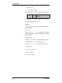
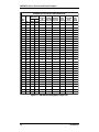
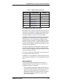
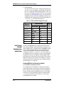
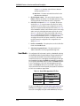
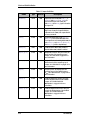
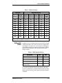
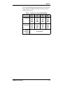
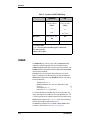
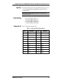
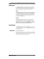
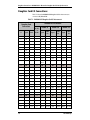
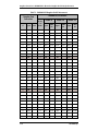
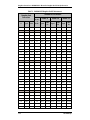
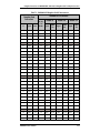
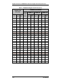
Table 4-3 Jumper Definitions
Name
Type
Default
Description
PLLSEL2[1]
LVTTL
LOW
Input Clock Select: If LOW, U16:DCLK[7] or
FCLKOUT (U14:PLL1A or HDR_CLKOUT) is
selected as the input clock. If HIGH, the
U16:PLL2B_N (U14:PLL1B_N) pair is selected as
the input clock.
MODE[2:1]
3-Level
HIGH
Output Mode: If HIGH, clock outputs disable to
high-Z state. If LOW, clock outputs disable to
“HOLD-OFF’ mode. If MID, clock outputs disable
to factory test mode.
INV2[1]
3-Level
MID
Invert Mode: When HIGH, clocks CCLK[3:0]
(ECLK[3:0]) are inverted. When MID, these
clock outputs are non-inverting. When LOW, the
pairs CCLK[1:0] and CCLK[3:2] (ECLK[1:0]
and ECLK[3:2]) will be complementary.
LVTTL
LOW
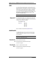
Feedback Disable: When HIGH, feedback is
disabled. When LOW, feedback is enabled.
RB[C-F]F[1:0]
3-Level
MID
Output Phase Function: Each pair controls the
phase function of the respective group of
outputs. See “Clock Skew” on page 4-12 for
more information.
[C-F]DS[1:0]
3-Level
LOW
Output Divider Function: Each pair controls the
divider function of the respective group of
outputs. See “Clock Division” on page 4-11 for
more information.
FS[2:1]
3-Level
LOW
Frequency Select: The input specifies the
operating range of the nominal frequency
(fNOM). See “General Control” on page 4-11 for
more information.
FBF0[2:1]
3-Level
LOW
Feedback Output Phase Function: The input
controls the phase function of the feedback
outputs. See “Feedback and Clock
Multiplication” on page 4-11 for more
information.
FBDS[1:0][2:1]
3-Level
MID
Feedback Output Divider Function: Each pair
controls the divider function of the feedback
outputs. See “Feedback and Clock
Multiplication” on page 4-11 for more
information.
FBDIS[2:1]
4-10
The DINI Group