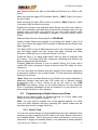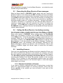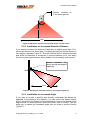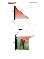
1
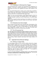
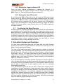
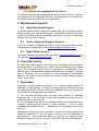
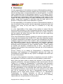
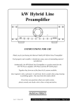
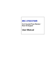
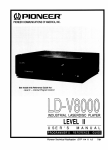
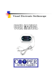
User Manual
a
product
Please ensure that you read the VoiceAlert System 6 Operating
Instructions included in the VA6000S starter kit, before reading this
manual.
Pay close attention to the guarantee conditions.
VoiceAlert User Manual
Table of Contents
1Introduction.......................................................................................................................4
1.1VA6000S Starter Kit...................................................................................................4
1.2Power requirements...................................................................................................4
1.3Features.....................................................................................................................4
1.4Accessories...............................................................................................................4
2Configuration of Base Receiver and Sensors...................................................................5
2.1Programming One Sensor per Zone .........................................................................5
2.2Programming multiple Sensors per Zone...................................................................6
2.3Recording the Base Receiver Zone messages..........................................................7
2.4Setting the Base Receiver low battery warning..........................................................7
2.5Installing Sensors......................................................................................................7
2.6Important Internal Sensor Settings..........................................................................10
2.7 Positioning the Base Receiver................................................................................11
3VoiceAlert Advanced Operation......................................................................................11
4VoiceAlert Troubleshooting.............................................................................................12
4.1Human Error............................................................................................................12
4.2Sensor Continuously Activating the Base Receiver (looping)..................................12
4.3Sensor not Activating the Base Receiver.................................................................12
5Wirelessalert Support......................................................................................................14
5.1Agent Technical Support..........................................................................................14
5.2Online Technical Support Contact...........................................................................14
5.3Head Office Contact................................................................................................14
6Copyright notice..............................................................................................................14
7Guarantee.......................................................................................................................14
8 Disclaimer......................................................................................................................15
Table of Figures
Figure 1: VoiceAlert Base Receiver and PIR Sensor..........................................................4
Figure 2: VA6000T wireless outdoor PIR sensor (VA-tx)....................................................5
Figure 3: Mini Transmitter (m-TX).......................................................................................5
Figure 4: VA-tx Sensor internal layout.................................................................................5
Figure 5: PIR Sensor mounted at standard height / no filter insert......................................8
Figure 6: PIR Sensor mounted low down and angled slightly up........................................8
Figure 7: PIR Sensor mounted on angled block of wood....................................................9
Figure 8: PIR Sensor with horizontal filter inserted.............................................................9
Copyright InFocus Trading 111 cc, 2009
2
VoiceAlert User Manual
Glossary of Terms
DIP
Dual Inline Package
JUS
VoiceAlert 12V Power Supply
LED
Light Emitting Diode
LLB
Long Life Battery
MHz
Megahertz
MIC
Microphone
m-TX
Mini Transmitter
PIR
Passive Infrared
UPS
Uninterrupted Power Supply
VA6000S
VoiceAlert Starter Kit
VA6000T
Additional VoiceAlert PIR Sensor
Copyright InFocus Trading 111 cc, 2009
3
VoiceAlert User Manual
1 Introduction
Please read the VoiceAlert System 6 Operating Instructions pamphlet
included in the VA6000S starter kit before continuing in order to
understand the basic radio operating principle behind VoiceAlert System 6.
Please note: ‘Sensor’ will be used as a generic term for any device used
for triggering Zones on the VoiceAlert Base Receiver.
1.1
VA6000S Starter Kit
Figure 1: VoiceAlert Base Receiver and PIR Sensor
The VA6000S starter kit forms the basis of the VoiceAlert system. It
consists of Base Receiver (VA-rx) and one VA6000T PIR Sensor (VA-tx)
(Figure 1).
You will seldom use the starter kit on its own unless you only need to
monitor a single Zone. Most applications require more than one Sensor.
Please contact your WirelessAlert agent if you wish to purchase additional
Sensors.
1.2
Power requirements
Base Receiver requires 12Volts to operate (e.g. 12V JUS transformer
power supply supplied in the starter kit).
Sensor requires a standard 9V battery (gives average six months
operation), 11.7V Long Life Battery (LLB) or 9V rechargeable battery.
1.3
Features
Basic features are listed in the VoiceAlert System 6 Operating
Instructions pamphlet (please read this before continuing).
1.4
Accessories
In addition to extra V6000T Sensors (VA-tx) (Figure 2), a Mini Transmitter
module (m-TX) (Figure 3), is also available for operation with the Base
Receiver. The m-TX module allows for a range of 3rd Party detection
devices (Infrared PIR, point-to-point beam, pressure mat, vibration switch,
and or tripwire) to be wirelessly coupled with the Base Receiver. Other
accessories include 433 MHz signal repeaters and a range of high gain
antennas for improving Sensor signal transmission and reception.
Operation of these accessories is not covered in this manual. Please
contact your WirelessAlert agent for further information.
Copyright InFocus Trading 111 cc, 2009
4
VoiceAlert User Manual
Figure 2: VA6000T wireless outdoor PIR sensor (VA-tx)
Figure 3: Mini Transmitter (m-TX)
2 Configuration of Base Receiver and Sensors
Please read the VoiceAlert System 6 Operating Instructions pamphlet
before continuing.
Follow the instructions below carefully to ensure optimal configuration of
your Sensors and Base Receiver.
2.1
Programming One Sensor per Zone
SW 1
DIP Switch
VR 1
J1
SW 2
Battery
connector
PIR optic
Figure 4: VA-tx Sensor internal layout
Make sure the Base Receiver is turned off using the on/off switch.
Remove the VA-tx Sensor cover and connect battery to the connector
(Figure 4). Make sure that the terminals of connector snap firmly onto
the battery’s terminals. Loose battery connectors can lead to low battery
messages and other looping issues (See Troubleshooting Chapter).
Set a unique code on the DIP switch (Figure 4). Make sure to record all
DIP codes for all Sensors as this will ensure proper management of Zones
Copyright InFocus Trading 111 cc, 2009
5
VoiceAlert User Manual
and Sensors should you wish to add additional Sensor/s to a Zone in the
future.
Make sure that the trigger LED indicator Switch 1 (SW1) (Figure 4) is set to
the on position.
Make sure that the Optic PIR is set to on position (SW2) (Figure 4). Optic
is on when SW2 is flicked to the right.
Replace the Sensor cover and then place Sensor out of the way, where it
won’t be accidentally activated (this is particularly important when you are
working with more than one Sensor as you don’t want random radio
signals interfering while attempting to program a specific Sensor onto a
Zone).
Slide the Base Receiver Setup switch to PROGRAM.
Locate chosen Sensor and activate it by waving your hand in front of its
lens. You will see the trigger LED illuminate to indicate that the Sensor has
been triggered.
The Setup LED on top of Base Receiver will in turn illuminate to indicate
that the trigger signal from the Sensor has been received and Base
Receiver is waiting for you to allocate Sensor to a Zone.
Press the Zone (1–6) ‘black push-switch’ that you wish to associate with
the Sensor. The Setup LED with extinguish, indicating that Sensor has
been programmed onto that Zone.
Program additional Sensors in turn to specific Zones (2-6) each with a
unique DIP code (remember to keep a record of the DIP codes for future
reference).
You can also label the Sensors with their specific Zone number (label with
a permanent marker or use a small sticker). This will help when identifying
Sensors in the future.
*Note* Make sure the Base Receiver is off before you connect batteries to
additional Sensors that have their DIP codes set to Sensors already
programmed onto a Zone. Failure to do so will result in the LOW
BATTERY low battery events on the Base Receiver for that particular
Zone. Low battery messages can be an irritation to try and remove if you
have multiple Sensors on your property.
2.2
Programming multiple Sensors per Zone
Match all DIP switch codes for Sensors specific to a Zone. Label each
Sensor with its Zone specific number (1 – 6).
Note: You only need to program one of the Sensors specific to a Zone
since the other Sensors will have matching DIP switch codes and will
therefore also be set to trigger that Zone.
2.2.1 Useful Trick
You can use a loose Sensor to shift installed Sensors onto a different Zone
number by simply matching the DIP code of the loose Sensor with that of
the installed Sensor. This is obvious but often overlooked; it can be very
strenuous to trigger an installed Sensor in an awkward or distant position
Copyright InFocus Trading 111 cc, 2009
6
VoiceAlert User Manual
while attempting to program it into the Base Receiver – so imitate the code
instead using a loose Sensor.
2.3
Recording the Base Receiver Zone messages
Slide the Setup Switch to RECORD. Speak clearly with your mouth at a
distance of about 15 cm away from the MIC situated on the top of the Base
Receiver and record your specific Zone message. Return the slide switch
to the RUN position when finished. There are six seconds of recording time
available for each Zone. Make use of the full six seconds by repeating a
message multiple times (e.g. “intruder in driveway!”, “intruder in driveway!”,
“intruder in driveway!”) to maximize the time that the Base Receiver is
reporting a trigger event. This will maximize the chance of hearing the
message. . If the PGM LED is flashing at any stage, you can press the
PLAYBACK button, and Base Receiver will broadcast all Zones that have
recently been activated.
2.4
Setting the Base Receiver low battery warning
You may want to hear a specific message e.g. “Low Battery on Sensor”
when a Sensor’s battery is getting low. To record this message, move the
Setup slide switch to RECORD. While holding down the PLAYBACK
button, say “Low Battery on Sensor” into the MIC. Return the slide switch
to the RUN position. To test the low battery message, press button #1 for 2
seconds. When any of the VA-6000T Sensor/Transmitters experience a
low battery condition, the LOW BATTERY LED will flash on the top of the
Base Receiver. It will also sound the Low Battery Message. Pressing the
PLAYBACK button, will broadcast Zone messages, followed by Low
Battery Message to identify any Sensors, with low batteries. After a new
battery is installed, trigger the Sensor again to cancel the low battery
message.
2.5
Installing Sensors
Once you have programmed the Sensors onto their respective Zones, you
will need to position the Sensors in and around your property such that
they give optimum detection while minimizing the chance of false triggers.
The VoiceAlert System 6 Operating Instructions Manual recommends
mounting the Sensors 2.2m above the ground, parallel to the mounting
surface. This is suitable for most applications however there are certain
situations that require Sensor to be mounted higher or lower and angled
either slightly up or down.
2.5.1 Standard Installation of Sensor
If you want to monitor a general area with no obstructions or pets then
follow the recommended height for mounting Sensors (2.2m) with the
Sensor parallel to the surface you have mounted it onto and no filter
inserts (Figure 5).
Copyright InFocus Trading 111 cc, 2009
7
VoiceAlert User Manual
Sensor mounted at
2.2m above ground
72°
12m
16m
Figure 5: PIR Sensor mounted at standard height / no filter insert.
2.5.2 Installation for Increased Detection Distance
If you want to increase the distance of detection to slightly more than 12 m,
secure the Sensor low down (app. 1m above ground) and tilt the Sensor to
face slightly upwards (Figure 6). This will shift the field of detection forward
and allow for detection of movement in some instances up to 15m away
from the sensor (performance will be subject to surrounding environment).
Sensor mounted 1m
above ground and angled
slightly up.
Wall
15m
Figure 6: PIR Sensor mounted low down and angled slightly up.
2.5.3 Installation for Increased Angle
If you want to monitor a specific area directly underneath the Sensor as
apposed to movement in the distance, you can mount the Sensor higher
than 2.2m and tilt the Sensor to face downwards. Secure the Sensor to an
angled block of wood and then mount the block onto a surface. This will
allow you to obtain the increased angle that you wish to set the Sensor
(Figure 7).
Copyright InFocus Trading 111 cc, 2009
8
VoiceAlert User Manual
Sensor mounted on
angled block of wood.
Wall
Figure 7: PIR Sensor mounted on angled block of wood.
2.5.4 Installation for Pet Friendly Operation
If there are large dogs on your property, insert a horizontal filter to make
the area of detection more horizontal than vertical. This will customize the
PIR detection area to a level where the dog (at height of head or tail) will
pass underneath and not cause activation, but human intruders will still be
detected (Figure 8).
Sensor mounted at height
above ground and with
horizontal filter insert to
prevent false trigger from
pets.
Wall
Figure 8: PIR Sensor with horizontal filter inserted.
Copyright InFocus Trading 111 cc, 2009
9
VoiceAlert User Manual
2.5.5 Installation for Reducing False Triggers
Use the horizontal filter to create a more horizontal area of detection. For
example, if you wish to exclude large plants of a certain height directly
underneath the Sensor from triggering the Sensor when blowing in the
wind.
Use the vertical Sensor filter to create a more vertical area of detection.
For example, if you share part of a driveway with your neighbour or if a
portion of the back yard contains a tree that blows in the wind. You can
use the vertical filter to exclude these false trigger areas.
*Note* You must remove branches or other foliage that grow in front of a
sensor over time as these could possibly lead to false triggering. A
schedule of periodic inspections must be implemented to cut away foliage
re-growth.
*Note* Do not mount the Sensor pointing in the direction of a swimming
pool. Sunlight reflecting off the pool’s surface onto the Sensor may cause
false triggers.
2.5.6 Protection from direct sunlight
Direct sunlight onto the Sensor can eventually lead to discoloration of the
Sensor cover. If possible, mount Sensors so they receive slight shading
from direct sunlight. If you have to mount Sensor on a wall that receives
direct sunlight then consider using a DIY, PVC cover to provide some
shading. Make sure you do not cover the lens of the filter.
2.5.7 Use of long-range lens
The long-range lens increases the infrared detection range from 12m to
30m. Be aware that the increased distance narrows the field of detection.
Long range Sensors will be more efficient at detecting objects moving
perpendicularly across the field of detection (left to right or right to left) as
apposed to movement parallel to field of detection (moving toward/awayfrom Sensor). They are very useful for monitoring along the length of long
walls or fences where intruders could jump over to gain access to a
property.
2.6
Important Internal Sensor Settings
2.6.1 Setting a re-trigger delay
To extend Sensor battery life you should consider setting the re-trigger
delay dial VR1 (Figure 4) to 30 or more seconds (turn clockwise to
increase delay / anticlockwise to decrease delay). Only do this for Sensors
that you expect will experience high traffic - activation during non-critical
times - (e.g. You may consider setting a delay to prevent continuous
activation of Sensors by your garden employee working in the garden
during the day). A delay of not more than 20 – 30 seconds is
recommended for this type of situation.
If you do not have a gardener or domestic staff on your premises during
the day, you should leave the trigger delay at zero seconds. You will then
be alerted immediately and continuously upon intrusion.
Copyright InFocus Trading 111 cc, 2009
10
VoiceAlert User Manual
2.6.2 Setting the trigger indicator LED
Once you have finished programming / installing the Sensors, it is
recommended that the trigger indicator LED be turned off using switch
SW1 (Figure 4). This will also extend Sensor battery life.
2.6.3 Setting the Optic PIR on/off
If you flick switch SW 2 (Figure 8) to the left, then the PIR optic for that
Sensor will be off and only the external trigger connector block (J1) will be
operational. If SW 2 is flicked to the right then both the PIR optic and the
J1 external device connector will be active. Consult your WirelessAlert
Agent if you are interested in using External Devices to trigger the sensor
via the J1 connector block or how to make use of m-TX module to perform
the same function.
2.7
Positioning the Base Receiver
Suitable areas for positioning the Base Receiver include the main bedroom
or somewhere more central like the living area. Adjust the volume on the
Base Receiver to a level that is loud enough to hear whilst moving around
the interior of the house. Make use of a UPS or several power supply units
at different locations to make it easy to move VoiceAlert from one location
to the next. Make sure not to leave the Base Receiver lying around in a
vulnerable location where untrained fingers can get hold of it and
inadvertently reset or change settings on the unit.
3 VoiceAlert Advanced Operation
You may have noticed that there are four Relay and one Audio Outputs
present at the back of the Base Receiver (remove the small cover at the
back of unit to expose the Relays).
The use of the Relays and Audio Output requires a degree of electrical
wiring knowledge. If you are familiar with electronics and wiring of electrical
devices then you may want to make use of the Relays to control security
lights and or a siren. The audio output can be used to extend the audible
range of the VoiceAlert to other parts of your home using external desktop
speakers and or your home PA system. Please contact your WirelessAlert
agent for assistance if need be.
If you are interested in connecting external sirens and or security lighting to
your VoiceAlert but you do not have experience with electronics and wiring
of external device then please contact your WirelessAlert agent and they
will be able to assist you in this regard or refer you to a qualified
WirelessAlert technician.
Your WirelessAlert Agent will also be able to assist with multiple Sensor
installations on large properties. Large properties often require Sensors
placed a fair distance from the Base Receiver (often beyond the transmit
capabilities of a Sensor). It is extremely important to ensure that radio
signals from Sensors placed far away or behind potential radio impeding
objects still reach the Base Receiver with sufficient strength. Your agent
will have testing equipment to do the necessary tests and recommend
steps for improving signal strength if required.
Copyright InFocus Trading 111 cc, 2009
11
VoiceAlert User Manual
4 VoiceAlert Troubleshooting
4.1
Human Error
Domestic Staff can very often be VoiceAlert’s worst enemy. They may
inadvertently unplug the Base Receiver while cleaning in the main
bedroom and forget to plug it in again. You should dedicate a wall socket
to the Base Receiver power supply that cannot be accessed by
unauthorised persons. Make sure you explain to staff and children to leave
the wall plug alone and not to touch any of the buttons on Base Receiver!
4.2
Sensor Continuously Activating the Base Receiver
(looping)
4.2.1 Flat Battery in Sensor
This can occur if the battery inside the Sensor has become very flat (<<
8V). Please replace flat battery and reprogram Sensor onto the correct
Zone.
Be aware: Low battery reports are transmitted at a very high trigger rate
and at an elevated level of power – and this can *severely* interfere with
other 433MHz components (such as car immobilisers, gate and garage
doors, etc). Never let a low battery condition persist.
4.2.2 Misty conditions
If there is thick mist / fog in your area then there is a chance that moisture
may enter through the small hole in the Sensor base plate and collect on
some of the sensitive electronics. This can induce a continuous transmit
(looping) condition.
If you are going to be installing Sensors in extremely misty conditions then
wrap strong electrical tape around the entire Sensor (especially where face
plate meets base) to seal it completely. Make sure to cover the small hole
in the base of the sensor.
4.3
Sensor not Activating the Base Receiver
4.3.1 Primary checks
Sensor battery completely flat (change the battery).
Check Sensor SW2 – must be in the ON position for PIR detection.
Battery terminal connector must fit properly (not loose).
Make sure the Base Receiver is in the RUN mode.
Make sure the Base Receiver has not been accidentally re-programmed or
interfered with.
4.3.2 Large obstacles
Large obstacles (large trees, concrete walls, dense foliage, uneven terrain)
in between the Sensor/s and the Base Receiver can reduce signal strength
significantly. Ask your agent to assist you in repositioning the Sensor/s and
Copyright InFocus Trading 111 cc, 2009
12
VoiceAlert User Manual
or making using of WirelessAlert 433MHz Repeaters to ensure signal
strength is sufficient when measured at the Base Receiver.
4.3.3 Metal structures
Metal roofing/walls and other large metal structures are not suitable for
mounting Sensors onto or under as they can either block the radio signal
completely or substantially reduce signal strength. Even if the metal
structure is a couple of meters away from the Sensor, this can still cause
interference. Reposition the Sensor/s at least ten meters away from metal
structures. Ask your agent to assist you in repositioning the Sensor/s and
or making using of WirelessAlert 433MHz Repeaters to ensure signal
strength is sufficient when measured at the Base Receiver.
4.3.4 Spider/ insect interference
Ants and small spiders can enter the Sensor through the small hole in the
base of the Sensor. They tend to build nests / webs which can eventually
cause short circuits on some of the sensitive electronics.
Remove any insects and clean out the nest/web with a soft dry brush (soft
paintbrush).
If insect problems persist, you may need to plug the hole in base of the
Sensor with electrical tape or silicone.
4.3.5 Misty conditions
Misty conditions can act as a shield against radio signals. This will be
obvious if on a sunny day, your Base Receiver receives signals from
Sensors, but not on misty days. You can install outdoor repeaters and or
high gain antennas to rectify the signal strength. Contact your Agent to for
assistance with repositioning sensors and or placement of the repeaters to
maximise signal strength.
4.3.6 Persistent mist / fog
If there is thick persistent mist / fog in your area then moisture may enter
through the small hole in the base plate and collect on some of the
sensitive electronics. This may decrease signal strength substantially, and
or the battery may short circuit and run flat very quickly. If you are going to
be installing Sensors in extremely misty conditions then wrap strong
electrical tape around the entire Sensor to seal it completely. You must
also be very careful to make sure that the Sensor cover plate is correctly
replaced with its seal in place after changing batteries to prevent moisture
ingress.
4.3.7 Base Receiver’s UPS backup battery is flat
If you are using the UPS backup battery to operate your Base Receiver
always make 100% sure the UPS battery remains fully charged (charger
connected) otherwise you signal reception will appear reduced (Sensor will
appear to not be triggering the Base Receiver from far away). Always
make sure the charger is connected to the UPS and charge the UPS for at
least twelve hours before using it out in the field without charger
connected.
Copyright InFocus Trading 111 cc, 2009
13
VoiceAlert User Manual
4.3.8 Sensor not programmed onto Zone
The Sensor may not have programmed correctly onto a Zone or it has lost
its programming link with Base Receiver. Re-programme the Sensor onto
the correct Zone and then recheck for activation.
5 Wirelessalert Support
5.1
Agent Technical Support
If you are experiencing a particular problem with your VoiceAlert system,
please consult your WirelessAlert agent. WirelessAlert Agents have been
trained to provide technical assistance and advice on how to effectively
operate your VoiceAlert system.
5.2
Online Technical Support Contact
If you do not have a WirelessAlert Agent in your area then please contact
online technical support @ Email: [email protected]
5.3
Head Office Contact
For Sales and Agent Information please Email: [email protected] or
visit Website: www.wirelessalert.co.za
6 Copyright notice
All Information and images in this manual are copyrighted and proprietary
to WirelessAlert. The manual as a whole may be distributed and copied
freely, but no partial content may be used/copied or distributed in any
way. No part of WirelessAlert products (including any Hardware, Firmware
and or Software) may be copied or reverse-engineered. WirelessAlert
reserves the right to make changes to contents of this manual, without
notice, at any time.
7 Guarantee
VoiceAlert is guaranteed for a period of 12 months against defects in
materials or workmanship. Should your product become defective during
the guarantee period it will be repaired or replaced at the sole discretion of
WirelessAlert under the following conditions:
A: The unit and enclosure must not have been opened or otherwise
tampered with. If the enclosure of any unit has been opened at all, the
guarantee will be null and void.
B: The guarantee does not cover damage resulting from excessive input
voltages, lightning, power surges or water damage. If any of these
conditions are detected during
assessment, the guarantee will be null
and void.
Assessment and opinion as to the status of each unit with regards to the
conditions named in “A” and “B”, above, will be at the sole discretion of
WirelessAlert. This guarantee does not provide for shipping costs.
Shipping costs will be for the account of the user under all circumstances.
Copyright InFocus Trading 111 cc, 2009
14
VoiceAlert User Manual
8 Disclaimer
It is the responsibility of all installers and users of WirelessAlert products to
read and fully understand manuals supplied with the products, to comply
with all warnings and to communicate these to relevant parties. It must be
clearly understood that no WirelessAlert product is a ‘life saving’ device,
and installers and users of WirelessAlert systems indemnify WirelessAlert;
its management, shareholders, staff and suppliers, of all claims in this
regard. No claim may be brought in respect of WirelessAlert component or
product usage that is greater in total value than the retail value of the
product or component itself at the installation in question.
It is the responsibility of all installers and users of WirelessAlert products to
test all elements of the product, and all associated component parts and
settings upon setup, at any time that it is modified or in any way
managed.
It is the responsibility of the owner of the system to ensure that the
functions and functionality of their WirelessAlert product and all associated
component parts and settings be tested at least once a week. Failure to
test any aspect will further void any claim that an end user might bring
against developers and suppliers.
Given that WirelessAlert products operate as wireless systems and must
comply with the limitations that ICASA, FCC, and other authorities impose
on wireless transmission strengths; and given that atmospheric and other
conditions might from time to time create or alter non-functional state for
the WirelessAlert system and its components, the Suppliers expressly
state that no guarantee of function can be given even when tests have
previously proven successful for one or another function. These vagaries
of function are therefore considered Acts of God - and provide the
Suppliers with insulation from prosecution that such Act of God conditions
generally provide.
InFocus Trading 111 cc trading as “WirelessAlert” in association with
developers and distributors of WirelessAlert products will under no
circumstances be held liable for any injuries or damages that result from
the use of this product.
If any part of this disclaimer is found by a competent court to be invalid or
non applicable, it will have no effect on the enforceability of other terms.
Much effort has been made to ensure the contents of this manual are
complete, informative, easy and interesting to read, and accurate. InFocus
Trading 111 cc trading as “WirelessAlert” in association with developers
and distributors of WirelessAlert products, cannot be held liable for any
damages directly or indirectly resulting from any errors in any manual.
It is the responsibility of the individual who reads this manual and uses
WirelessAlert products to communicate all of its contents to all of those
who will be impacted by the use of WirelessAlert products. By this
disclaimer and to these terms, InFocus Trading 111 cc, WirelessAlert
Technologies cc, Polygon Industries cc and all employees or
representatives are expressly relieved of all common law or statutory
responsibility for non-performance of this product.
Copyright InFocus Trading 111 cc, 2009
15