1
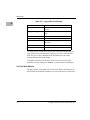
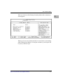
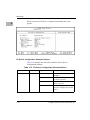
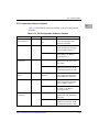
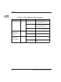
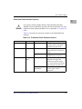
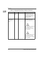
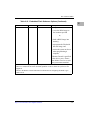
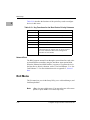
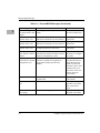
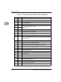
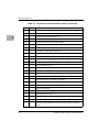
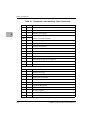
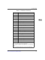
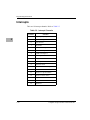
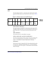
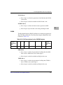
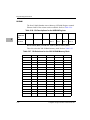
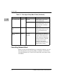
Programming Information
ALARM_A (Bit 3) and ALARM_B (Bit 2)
❏
Set to a logic 1 to allow the generation of an IRQ when the
ALARM_A or ALARM_B go active. Alarm is active when logic 0.
❏
Write a logic 0 to this bit to disable an IRQ for this event.
ENUM (Bit 4)
❏
Set to a logic 1 to allow the generation of an IRQ when the ENUM
event occurs.
❏
Write a logic 0 to this bit to disable an IRQ for this event.
5
ENABLE (Bit 7)
❏
Set to a logic 1 to allow the listed events to generate an IRQ.
❏
Write a logic 0 to prevent the events from generating an IRQ.
ALEN
The Alarm Enable Register (ALEN) defines the events that generate an
Alarm output. Refer to Table 5-21.
Table 5-21. Bit Descriptions for the ALEN Register
7 (most
significant
bit)
6
5
4
3
2
1
0 (least
significant
bit)
ENABLE
RES
RES
ENUM
ALARM_A
ALARM_B
TEMP
SMB
SMB ALERT (Bit 0)
5-26
❏
Set to a logic 1 to allow the generation of an Alarm when the SMB
Alert is active. SMB Alert is active when logic 0.
❏
Write a logic 0 to this bit to disable an Alarm for this event.
Computer Group Literature Center Web Site