1
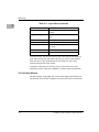
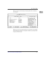
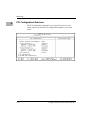
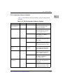
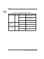
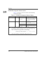
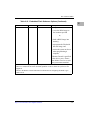
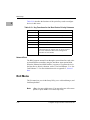
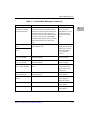
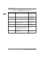
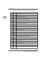
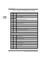
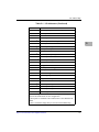
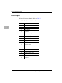
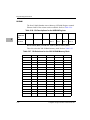
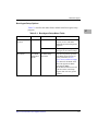
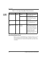
I/O Address Map
Table 5-1. I/O Addresses (Continued)
Address
Function
0080-009F
DMA page register, POST checkpoint
00A0-00BF
Interrupt controller 2
00C0-00DF
DMA controller 2
00F0
Reset coprocessor
0170-0177
2
Secondary IDE channel (opt)
01F0-01F7
2
Primary IDE channel
0278-027F 3
Parallel port 2 (opt)
02E8-02EF
3
Serial port 4 (opt)
02F8-02FF
2
Serial port 2 (default)
0376-0377
2
Secondary IDE port (opt)
0378-037F
2
Parallel port 1 (default)
03BC-03C3
3
Parallel port 3 (opt)
03E8-03EF
3
Serial port 3 (opt)
03F0-03F5
Floppy channel
03F6-03F7
03F8-03FF
Primary IDE and floppy
2
Serial port 1 (default)
040A-043F
DMA scatter/gather
0480-048F
DMA high pages
04D0-04D1
Edge/level interrupts
04D6
DMA2 extended mode
0678-067A
3
Parallel port 2 (opt)
0778-077A
3
Parallel port 1 (opt)
07BC-07BE
0CF8-0Cff
5
3
Parallel port 3 (opt)
PCI configuration
1
The Watchdog timer and LM78 are normally disabled but you can
relocate and enable them via PCI configuration.
2
These ports are available if the listed function is not enabled in the
BIOS.
3 This is an alternate range that you can select in the BIOS setup.
http://www.motorola.com/computer/literature
5-5