1
Training manual
COPYRIGHT © 2013 IGE+XAO. All rights reserved
Training manual
V7R2
Training manual
COPYRIGHT © 2013 IGE+XAO. All rights reserved
Copyright
Copyright (c) July 2013 IGE-XAO. All rights reserved. No part of this manual, or any portion of it,
shall be reproduced, transcribed, saved or translated, under whatever form and by whatever means,
without written authorization from IGE-XAO, 25 bld Victor Hugo, Immeuble Le Pythagore, BP 90312
31 773 COLOMIERS CEDEX FRANCE.
Page 2
A. Introduction
Training Manual
COPYRIGHT © 2013 IGE+XAO. All rights reserved
Table of Contents
A
INTRODUCTION
A.1.
A.2.
THE W ORKSPACE
FOLDERS AND FILES
11
12
15
B
CREATING A NEW WORKSPACE
16
C
DRAWING THE FIRST PAGE OF A CIRCUIT DIAGRAM
18
C.1.
C.2.
C.3.
C.4.
D
CREATING PAGE 1
GRID
DRAWING PAGE 1
WORKING WITH A ZOOMED PART OF THE DRAWING
DRAWING THE SECOND PAGE OF A CIRCUIT DIAGRAM
D.1.
D.2.
D.3.
CREATING PAGE 2
DRAWING PAGE 2
COPYING EXISTING ELEMENTS ON PAGE 2
18
19
20
26
27
27
28
37
E
DRAWING CABLES
45
F
ADDITIONAL PROCESSING OF CIRCUIT DIAGRAMS
48
F.1.
F.2.
F.3.
F.4.
G
USING CROSS-REFERENCE SYMBOLS
USING INFO TEXT SYMBOLS
PAGE INDEX
TEXTS
HYPERLINKS
G.1.
MANAGING THE HYPERLINKS
50
52
53
55
58
58
H
REDLINING
59
I
PRINTING
61
I.1.
PRINT
61
J
DATABASE LISTS
63
K
GRAPHICAL LISTS
66
K.1.
K.2.
K.3.
GENERATING A GRAPHICAL LIST
DEFINE PAGE TEXTS PEMANENTLY
GENERATING ALL DESIRED GRAPHICAL LISTS IN ONE STEP
66
68
68
L
INSERTING OTHER DOCUMENTS
69
M
CREATING COMPONENTS
70
M.1. CREATING A COMPONENT
M.2. CHANGING EXISTING SYMBOLS
M.2.1. Deleting Elements
M.2.2. Adding Elements
M.2.3. Adding Texts
M.2.4. Moving Texts
M.3. HANDLING GRAPHICS
M.4. USING AVAILABLE COMPONENTS
A. Introduction
70
75
75
76
76
78
81
83
Page 3
Training manual
COPYRIGHT © 2013 IGE+XAO. All rights reserved
M.5. INFORMATION ABOUT SPECIAL COMPONENTS AND THEIR CREATION
M.5.1. Contacts
M.5.2. Terminals
M.5.3. Multi-Layer Terminals (standard)
M.5.4. Connectors
M.5.5. Cross-Reference Symbols
M.5.6. Info Text Symbols
M.5.7. Components with Auxiliary Contacts
M.5.7.a. Symbols with cross reference as text
M.5.7.b. Symbols with graphical contact symbols in it
M.5.7.c. Examples of Components with Auxiliary Contacts
M.5.8. PLC Components
M.5.8.a. Examples of PLC Components
M.5.9. Smart black box symbols
M.6. CABLE SYMBOLS
M.6.1. Creating User-Defined Cable Symbols
M.6.2. Creating User-Defined Cables
M.6.3. Settings for Cables
M.7. INFORMATION ABOUT COMPONENT INSERTION
M.7.1.a. Relay Coils
M.7.1.b. Terminals
M.7.1.c. Assigning a Component Name
M.8. INFORMATION ABOUT SYMBOL DATABASES
M.8.1. Creating a New Database
M.8.2. Directories and Names
M.8.3. Working with Symbol Folders
M.8.4. Working with Symbols in the Database
M.8.5. Favorites Symbol Folder
M.8.6. Symbol Database Connection to Modules
N
GROUPS
N.1.
N.2.
N.3.
N.4.
O
BASIC OPERATIONS WITH TEMPLATES AND STANDARD SHEETS
O.1.
O.2.
O.3.
O.4.
P
CREATING A STANDARD SHEET
CREATING A PAGE TEMPLATE
CREATING A W ORKSPACE TEMPLATE
QUICKREFERENCE TEMPLATES AND STANDARD SHEETS
TEMPLATES AND STANDARD SHEETS FOR GRAPHICAL LISTS
P.1.
P.2.
P.3.
Q
CREATING A GROUP
UNGROUPING SELECTED ELEMENTS
MOTOR TERMINALS AND SIMILAR COMPONENTS
CONNECTORS: USING SEVERAL PLUGS AND JACKS TOGETHER
CREATING TEMPLATES FOR GRAPHICAL LISTS
FORMATTING TEMPLATES FOR GRAPHICAL LISTS
GENERATE COVER SHEETS FOR GRAPHICAL LISTS
EXTERNAL DATA TRANSFER
Q.1.
Q.2.
Page 4
DATA TRANSFER THROUGH DWG/DXF/DXB FORMAT
PIXEL IMAGES TRANSFER
85
85
85
86
87
88
88
89
89
90
90
91
92
95
96
96
97
99
100
100
100
100
101
101
101
101
101
102
102
104
104
107
107
108
109
110
118
120
122
123
123
125
132
133
133
134
A. Introduction
Training Manual
COPYRIGHT © 2013 IGE+XAO. All rights reserved
R
PROCESSING A WORKSPACE
R.1. ADDITIONAL OPTIONS FOR CROSS-REFERENCES
R.2. PLC FUNCTIONALITIES IN THE STANDARD LEVEL
R.2.1. Using the PLC database
R.3. ADDING AND DELETING PAGES
R.4. COPY SINGLE PAGE IN THE SAME W ORKSPACE
135
135
136
136
137
137
S
EASY EDITING IN DATABASE LISTS
138
T
CONTACT MIRROR AND TYPE DATABASE
139
T.1.
T.2.
T.3.
U
MANIPULATING THE TYPE DATABASE
USING TYPES IN THE CIRCUIT DIAGRAMS
AUXILIARY CONTACTS INSIDE ADD-ONS FOR COILS AND SUBTYPES
ADDITIONAL HINTS ABOUT COMPONENT MANAGEMENT IN THE TYPE DATABASE
U.1. CABLE MANAGEMENT
U.2. MANAGEMENT OF CONNECTORS
U.3. CHANNEL DEFINITION FOR PLC I/OS
U.4. BLACK BOXES
U.4.1. Assigning of types to intelligent black box symbols
U.4.2. Creating a Black Box from Channel Information
V
ADDITIONAL HINTS ABOUT THE TYPE DATABASE
V.1.
V.2.
V.3.
V.4.
V.5.
V.6.
V.7.
W
SEARCHING AND COPYING IN THE TYPE DATABASE
COMPLETING COMPONENTS
USING THE COMPONENT EXPLORER
IMPORTING AND EXPORTING ARTICLE MASTER DATA
MODIFYING EXISTING TYPES IN THE PROJECT
DISPLAYING INFORMATION ON THE EQUIPMENT FROM THE TYPE DATABASE
DEFINE WHICH TYPE DATABASE TO USE WITH A PROJECT
WIRE PROPERTIES
W.1.
W.2.
W.3.
W.4.
W.5.
W.6.
W.7.
W.8.
X
WIRE DIRECTION
CHANGING TARGETS
DEFINING A LINK
GRAPHICAL W IRE NUMBERING
SIGNAL PROPERTIES
WORKING WITHOUT SIGNAL PROPERTIES
VIEW AND CHANGE W IRE ATTRIBUTES
DEFINE THE POSITION OF THE W IRE TEXT
TERMINAL MATRIX
141
147
150
152
152
155
157
159
159
159
161
161
162
164
166
167
167
167
168
168
171
173
174
176
177
178
179
181
X.1. GENERATING A TERMINAL MATRIX
181
X.2. HANDLING MULTI-LAYER TERMINALS
183
X.3. CREATING A TEMPLATE FOR A TERMINAL MATRIX
184
X.3.1. General Information
184
X.3.2. Drawing Graphics Associated with Each Terminal – One Geometry for All Terminals
190
X.3.3. Drawing Graphics Associated with Each Terminal – One Specific Geometry for Each Kind
of Terminal
192
X.4. DRAW MORE THAN ONE TERMINAL STRIP PER PAGE
195
A. Introduction
Page 5
Training manual
COPYRIGHT © 2013 IGE+XAO. All rights reserved
Y
CABLE PLAN WITH GRAPHICS
Y.1.
Y.2.
Y.3.
Y.4.
Z
CREATING A CABLE PLAN WITH GRAPHICS
CREATING A TEMPLATE FOR CABLE PLANS WITH GRAPHICS
SHOWING NOT USED CABLE CORES IN CABLE PLAN
CABLE PLAN WITH SHIELD INFORMATION FOR CABLES
WIRING LISTS
Z.1. GRAPHICAL W IRING LIST
Z.1.1. Creating an Excel/Text File
199
201
201
203
203
207
209
210
AA
FUNCTION AND LOCATION
215
BB
REVISION MANAGEMENT
220
CC
ADVANCED FUNCTION/LOCATION AND PRODUCT MANAGEMENT
221
CC.1.
CC.2.
DD
DATABASE FOR FUNCTION/LOCATION AND PRODUCT MANAGEMENT
USING NESTED ASPECTS
COMPLEX MODIFICATIONS OF THE DATABASE LISTS
DD.1.1.
DD.1.2.
DD.1.3.
DD.1.4.
DD.1.5.
DD.1.6.
DD.1.7.
DD.1.8.
DD.1.9.
EE
221
229
233
Product Editor
Terminal Editor
Cable Editor
Connector Editor
Signal Editor
Wire Editor
Function/Location Editor
Document Editor
REDLINING OBJECTS LIST
233
233
235
235
235
235
236
236
237
ADVANCED PROCESSING OF A PROJECT
238
EE.1.
NAVIGATION IN THE PROJECT
238
EE.2.
WORKING WITH AUTOMATICALLY GENERATED CONNECTIONS
239
EE.3.
ORTHOGONAL W IRING
240
EE.4.
ADVANCED FUNCTIONALITY FOR CABLES
243
EE.4.1. Define Cable Names Automatically
243
EE.4.2. Display Cable Cores a Second Time
243
EE.5.
ADVANCED FUNCTIONALITY FOR POTENTIAL NUMBERING
244
EE.6.
COPYING PAGES
246
EE.6.1. Copy Single Page in the Same Workspace
246
EE.6.2. Copy Single Page in the Same Workspace or in Different Workspace
246
EE.6.3. Copy Multiple Pages Between Different Workspaces
248
EE.7.
CHANGING PAGE TEMPLATES
249
EE.8.
TRANSLATING A W ORKSPACE
250
EE.8.1. Displaying Several Translations at the Same Time
252
EE.8.2. Translation of Part Strings
252
EE.8.3. Updating Translation Text in a Sheet
252
EE.8.4. Looking up Texts in the Translation Database
254
EE.8.5. Exchanging the Source Languages of a Workspace
255
EE.9.
CHANGING THE FONTS AND ATTRIBUTES FOR ALL TEXTS IN THE W ORKSPACE, SYMBOL LIBRARIES
OR PAGE TEMPLATES
256
EE.10. PLC FUNCTIONALITIES IN THE ADVANCED LEVEL
259
EE.11. GENERATE GRAPHICAL LISTS IN ONE STEP
261
Page 6
A. Introduction
Training Manual
COPYRIGHT © 2013 IGE+XAO. All rights reserved
FF
CUSTOMIZING THE WORKSPACE/PAGE INFORMATION WINDOWS
262
GG
CUSTOMIZING THE WORKSPACE TREE
265
GG.1.
GG.2.
HH
HIDE UNNECESSARY DATABASE AND GRAPHICAL LISTS
SORTING OF DOCUMENTS IN THE W ORKSPACE TREE
USER-DEFINED SQL-QUERIES
HH.1.1.
HH.1.1.
II
Creating an SQL-Query for Adding a Database List in the Workspace Explorer
Definition of Graphical Formulas
TERMINAL PLAN
II.1. GENERATING A TERMINAL PLAN
II.2. CREATING A TEMPLATE FOR A TERMINAL PLAN
II.2.1. Drawing Graphics Associated with Each Terminal
II.2.2. Drawing Cables as a Grouping of Cable Cores
II.2.3. Drawing Cables/Geometry on Both Sides of the Terminals
II.2.4. Showing that Cable Cores are Used on Previous/Next Page
II.2.5. Symbols for a Terminal Plan
JJ
CONNECTOR MATRIX AND PLAN
JJ.1.
JJ.2.
JJ.3.
JJ.4.
KK
GENERATING A CONNECTOR MATRIX
CREATING A TEMPLATE FOR A CONNECTOR MATRIX
DRAW MORE THAN ONE CONNECTOR PER PAGE
CONNECTOR PLAN
TERMINAL ROW PICTURE PLAN
KK.1.
GENERATING A TERMINAL ROW PICTURE PLAN
265
266
268
268
273
275
275
276
279
279
282
283
285
286
286
287
288
290
291
291
LL
CABLE TERMINAL ROW PLAN
294
MM
PRODUCT ASSEMBLY LIST
295
MM.1.
NN
MULTICORES
NN.1.
OO
GENERATING A TEMPLATE FOR THE PRODUCT ASSEMBLY LIST
USING MULTICORES
INSERTING COMPONENTS NOT IN THE DRAWING VIA THE DATABASE EDITORS
OO.1. EDITOR FOR COMPONENTS W ITHOUT GRAPHICS
OO.2. INSERTING SPARE OR GROUND TERMINALS VIA THE TERMINAL EDITOR
OO.2.1. Handling Cables Without Graphics
OO.3. INSERTING SYMBOLS FOR COMPONENTS W ITHOUT GRAPHICS IN THE DIAGRAM (PICK LIST)
PP
AUTO DIAGRAM
PP.1.
INTRODUCTION
PP.2.
CREATING SYMBOLS (GROUPS)
PP.3.
PAGE TEMPLATES
PP.4.
EXCEL SPREADSHEET
PP.4.1. Project Data (ProjectInfo)
PP.4.2. Page Data (PageInfo)
PP.4.3. Select Symbol (Symbols)
PP.4.4. Defining Alias Names
PP.5.
AUTOMATIC GENERATION OF CIRCUIT DIAGRAMS
PP.5.1. The Autodiagram Command
A. Introduction
297
301
301
303
303
307
308
309
310
310
310
313
314
314
315
316
317
318
318
Page 7
Training manual
COPYRIGHT © 2013 IGE+XAO. All rights reserved
QQ
LISTS AND LABELS EDITOR
QQ.1. CREATING LABEL TEMPLATES
QQ.1.1. Files for Label Templates
QQ.1.2. Changing Label Templates
QQ.1.3. Printing Labels
QQ.2. CREATING LIST TEMPLATES
QQ.2.1. Files for List Templates
QQ.2.2. List Title (Text Object)
QQ.2.3. Header Lines
QQ.2.4. Group Header
QQ.2.5. Group Footer Lines
QQ.2.6. Data Lines
QQ.2.7. Footer Line
QQ.2.8. List Footer Line (Text Object)
QQ.3. EDITING LISTS
QQ.3.1. Changing Column Titles (Header Lines)
QQ.3.2. Changing a List (Font Size, Fields Order, Adding or Deleting Fields)
QQ.3.3. Changing the List Title
QQ.3.4. List Title with Questions
QQ.3.5. List Title with Generation Date
QQ.3.6. Filtering in the Lists
QQ.3.6.a. List of Parts for a Particular Manufacturer
QQ.3.6.b. List of Parts without Terminals
QQ.3.7. Calculations
QQ.3.7.a. Calculation of Order Costs
QQ.3.8. Line Numbering
QQ.4. DEFINING SQL-QUERIES FOR LISTS AND LABELS
QQ.4.1. Joining Two Lists
QQ.4.1.a. Joining Information from Cable List and Cable-Wires List
QQ.4.2. Filtering Double Records
QQ.4.2.a. List of Functions/Locations on Pages
QQ.4.3. Sorting a List
QQ.4.3.a. Order List
QQ.4.3.b. Cable Length Addition
QQ.4.3.c. Length Calculation for Cable Channels and Rails
QQ.4.4. Multiple Printing of Labels
QQ.4.5. Labels for Component Names with Defined Content
QQ.5. USEFUL TABLES IN ACCESS DATABASE
QQ.6. STATEMENT SUMMARY AND COMMANDS IN LISTS AND LABELS
QQ.6.1. SQL Statements
QQ.6.1.a. SELECT
QQ.6.1.b. SELECT DISTINCT
QQ.6.1.c. JOIN –clause
QQ.6.1.d. ORDER BY
QQ.6.1.e. WHERE/WHERE NOT
QQ.6.1.f. UNION ALL
QQ.6.1.g. Uppercase/ Lowercase
QQ.6.1.h. Logical Operators
QQ.6.1.i. Relational Operators
QQ.6.2. Commands in Lists and Labels
QQ.6.2.a. Conditions: If
Page 8
327
327
331
331
331
332
335
335
335
336
336
336
336
336
337
337
339
340
342
343
344
344
346
347
347
349
350
350
350
353
354
354
354
355
357
358
359
360
361
361
361
361
362
363
363
364
365
365
365
365
365
A. Introduction
Training Manual
COPYRIGHT © 2013 IGE+XAO. All rights reserved
QQ.6.2.b.
QQ.6.2.c.
QQ.6.2.d.
QQ.6.2.e.
QQ.6.2.f.
QQ.6.2.g.
RR
Upper$/Lower$
Val
Fstr$
AskString$
Len, Left$, Right$
Relational Operators
CABINET LAYOUT
RR.1. DRAWING CABINET LAYOUTS
RR.1.1. With the Cabinets Module
RR.1.2. Without the Cabinets Module
RR.2. USING LAYERS
RR.3. DIMENSION
RR.4. COMPARISON BETWEEN CIRCUIT DIAGRAMS AND CABINETS
SS
USEFUL TOOLS
SS.1.
SS.2.
TT
COMPRESSING PROJECTS
REORGANIZE W ORKSPACES
SETTINGS
TT.1.
SYSTEM SETTINGS
TT.2.
WORKSPACE PROPERTIES
TT.3.
PROPERTIES FOR CIRCUIT DIAGRAMS
TT.4.
PAGE PROPERTIES
TT.5.
CUSTOMIZING THE INTERFACE
TT.5.1. Quick Access Toolbar
TT.5.2. Define Hotkeys
TT.5.3. User Defined Categories
366
366
366
366
367
367
368
368
368
377
381
382
385
388
388
389
390
390
391
392
393
394
394
396
396
UU
COMMANDS EXPLORER
402
VV
INTELLIGENT DRAWING LEGACY MODULE
406
VV.1.
TOOLS FOR SCANNED DRAWINGS
407
VV.1.1. Importing Multiple Scanned Drawings in One Step
407
VV.1.2. Covering Scanned Symbols with an (White) Area ("BkSymbol" Command)
409
VV.2.
TOOLS FOR MAKING DXF/DWG IMPORTED DRAWINGS MORE INTELLIGENT
410
VV.2.1. Defining Patterns ("DefinePatterns" Command)
410
VV.2.2. Controling and Changing Patterns, Assigning Texts ("ShowPatterns" Command)
412
VV.2.3. Recognizing Patterns ("RecognizeDrawingPatterns" and "RecognizeWorkspacePatterns"
Commands)
414
VV.2.4. Displaying all Elements with Logic
414
A. Introduction
Page 9
Training manual
COPYRIGHT © 2013 IGE+XAO. All rights reserved
Page 10
A. Introduction
Training Manual
COPYRIGHT © 2013 IGE+XAO. All rights reserved
A
INTRODUCTION
By following this training manual step by step you will gain experience in using SEE Electrical.
If you have already worked with SEE Electrical, you can follow the examples step by step. You will
learn the fundamental SEE Electrical functions.
The first chapters contain information about the features used further in this Training Manual.
Chapters "Easy Editing in Database Lists" to "Function and Location" apply to SEE Electrical
Standard, chapters "Complex Modifications of the Database Lists" to "List and Label Editor" apply
only to SEE Electrical Advanced. Chapter "Cabinet Layout" requires SEE Electrical Standard, and
some examples require the Cabinets module in addition.
Abbreviations used in this training manual:
CA
CO
M
+
#
>
<Input>
T
I
A. Introduction
Select a category
Select a command
Select from pull-down menu
Select an element with the cursor
Keyboard entry
Select a field in a window
Type text or select element etc.
Click on tab in window
Select a toolbar icon
Page 11
Training manual
COPYRIGHT © 2013 IGE+XAO. All rights reserved
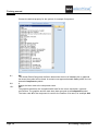
A.1. THE WORKSPACE
Most often a workspace in SEE Electrical contains circuit diagrams. Graphical lists are generated
automatically using the diagram information, for example:
List of Products
List of Terminals
List of PLC
List of Wires
List of Cables
List of Documents
etc.
Project data is used for the generation of the graphical List of Terminals (as well as terminal matrix in
Standard level), List of Cables and List of Products.
You can create drawings of cabinets or installation plans within a project.
SEE Electrical contains different modules that provide functions for drawing circuit diagrams,
installations, or cabinets. The availability of the appropriate module allows you to create the
examples.
Other documents can be added to the workspace in the Other documents area, for example Word
files or Excel spreadsheets.
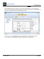
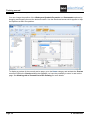
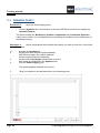
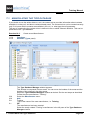
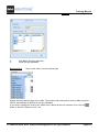
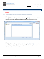
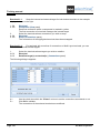
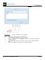
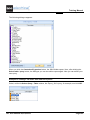
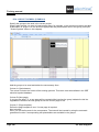
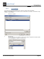
By default three areas appear on the screen when you launch SEE Electrical.
Page 12
A. Introduction
Training Manual
COPYRIGHT © 2013 IGE+XAO. All rights reserved
The Workspace/Symbols/Commands area is located on the left hand side in the SEE Electrical
window. The drawing area is located in the centre of the SEE Electrical window. The Properties area
is located on the right hand side in the SEE Electrical window.
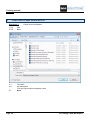
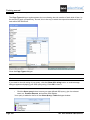
To display a list, go to the Workspace area, open Database lists and select the desired list.
You can toggle between Workspace, Symbols, Components and Commands.
A. Introduction
Page 13
Training manual
COPYRIGHT © 2013 IGE+XAO. All rights reserved
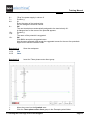
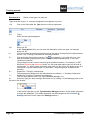
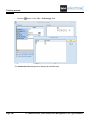
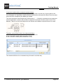
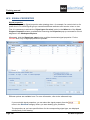
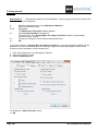
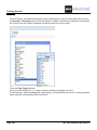
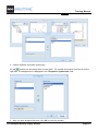
You can change the position of the Workspace/Symbols/Properties and Commands explorers by
dragging and dropping them at the desired location. Use the directional arrows which appear to drop
the explorers at their new position.
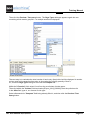
To display a preview of the currently active page, go to the Home category and activate the Preview
command. Within the Preview window that appears you have the possibility to zoom in and out the
page. See Working with a Zoomed Part of the Drawing for more details.
Page 14
A. Introduction
Training Manual
COPYRIGHT © 2013 IGE+XAO. All rights reserved
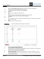
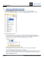
A.2. FOLDERS AND FILES
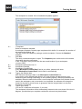
SEE Electrical uses the following folders and files:
< SEE Electrical V7 folder>
The program files of SEE Electrical are saved in this
folder.
...\PROJECTS
In this folder, you can find the workspace files of SEE
Electrical delivered by default.
Workspace files have the .SEP extension.
...\SYMBOLS
This folder contains the symbol databases in SEE
Electrical.
Symbol databases have the .SES extension.
The TYPES.SES database, required in the Standard and
Advanced levels is also stored here.
Please note that the SYSTEM.SES library is required for
internal purposes and must not be removed from this
folder.
If the Cabinet module is available, the IndexTable.SES is
used to create index tables.
....\TEMPLATES
This folder contains workspace and page templates,
templates for lists and labels. Fonts are saved here, too.
SEP: Workspace templates
TDW: Page templates
...\TEMPLATES\LABEL_SETTINGS
CABLESNEW.MDB or CABLESNEWIEEE.MDB that
contain settings for user defined cables.
DAT: Fonts
SLS files (used for creating labels for different printer
formats).
In addition, SEE Electrical Advanced uses the following files:
...\TEMPLATES
A. Introduction
In this folder, you can find the TRANSLATIONNEW.MDB
translation database used by SEE Electrical Advanced for
translating the workspaces.
Page 15
Training manual
COPYRIGHT © 2013 IGE+XAO. All rights reserved
B
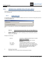
CREATING A NEW WORKSPACE
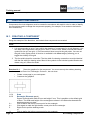
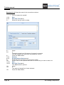
Exercise 2-1:
Create a new workspace.
1.CA
2.CO
File
New
3.>
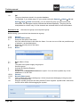
4.#
File name
My Workspace
You can type another workspace name.
Save
5.>
Page 16
B. Creating a New Workspace
Training Manual
COPYRIGHT © 2013 IGE+XAO. All rights reserved
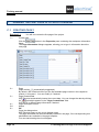
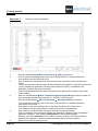
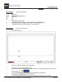
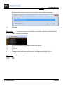
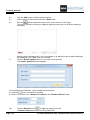
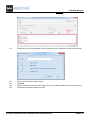
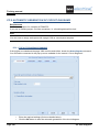
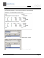
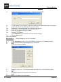
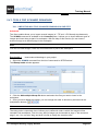
The workspace is created. A list of available templates appears.
6.>
7.>
8.>
9.#
10.>
11.#
12.>
13.#
<Template>
Select a workspace template.
A workspace template contains page templates which define, for example, the number of
columns in the drawing, etc.
The SEE Electrical installation package contains templates. Choose the Standard
template.
Click OK.
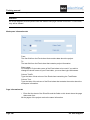
The newly created workspace is open. The Properties pane visible on the left contains
information about the workspace.
In the "File-name" field you can see the name and location of your workspace
(<name>.SEP).
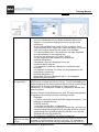
Workspace Description-line 01
Workspace Example
Workspace Created Date
If the "Workspace Created Date" field is not visible, please scroll down.
The "Workspace Created Date" field is filled in automatically.
Type in the desired date.
SEE Electrical shows the date in the Workspace Created Date line.
If you wish to use a different date format, you must change the date format in your
Windows system settings Depending on the operating system, different possibilities are
available. When the date format of the current computer is different from the date format
used in the workspace, and a conversion is not possible, the software will change the
format for the date to a text format, to guarantee that the original date is to be seen.
Workspace Created By
Type in your name.
You can fill in additional information, if you wish.
The workspace information will be automatically inserted in the norm sheet of the circuit
diagram, provided that your template contains the relevant text placeholders.
B. Creating a New Workspace
Page 17
Training manual
COPYRIGHT © 2013 IGE+XAO. All rights reserved
C
DRAWING THE FIRST PAGE OF A CIRCUIT DIAGRAM
C.1. CREATING PAGE 1
Exercise 3-1:
1.>
You will now create the first page of the project.
Create page
Click the
button in the Properties pane containing the workspace information
fields.
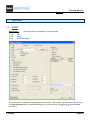
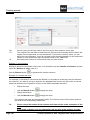
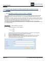
The Page information dialogue appears, allowing you to type in information about the
new page.
2.>
3.>
4.>
5.#
6.>
Page 18
Page
Page number: "1" (automatically suggested).
By default, SEE Electrical offers you the first available page number in the respective
module, in this case 1. You can modify it, if desired
Page Created Date
SEE Electrical automatically inserts the current date. You can change the date by clicking
the
field which appears in the "Page Created Date" field.
You can fill in different page information if desired.
Page Description-line 01
Motors
OK
Close the dialogue box.
SEE Electrical opens a new circuit diagram page.
The page information will be automatically inserted in the page, if the corresponding text
placeholders are available in the page template..
You can start drawing the circuit diagram.
C. Drawing the First Page of a Circuit Diagram
Training Manual
COPYRIGHT © 2013 IGE+XAO. All rights reserved
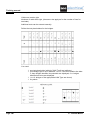
C.2. GRID
Using a grid you can align precisely geometrical elements, texts and components.
You can toggle the visibility of the grid by clicking the
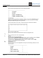
After clicking
icon in the Styles panel.
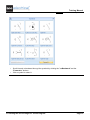
, the list of the default grid sizes appears:
If you choose “Other", you can set your own grid size.
Hint:
You can also define customised values to appear in the pull-down list of grid values. In order to do
this, you must modify the CAEGridSettings.xml file from the \Templates installation directory. This
file can contain no more than 10 grid values.
C. Drawing the First Page of a Circuit Diagram
Page 19
Training manual
COPYRIGHT © 2013 IGE+XAO. All rights reserved
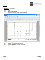
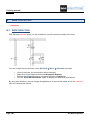
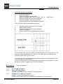
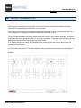
C.3. DRAWING PAGE 1
Exercise 3-2:
▪
Insert the Power supply group.
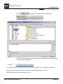
Click the Symbols tab in the left pane of the main SEE Electrical window to display the
Symbols Explorer.
This pane contains the Workspace, Symbols, Components and Commands Explorers.
If they are not visible, you can display them by activating the toolbars from the View panel of
the Home category.
Exercise 3-3:
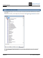
Select the database that contains the symbols you wish to work with. In this case,
select Examples.
1.T
2.
3.
4.
Activate the Symbols tab.
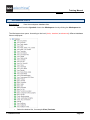
Double-click the Examples symbol database.
SEE Electrical opens the symbol database.
Various symbol folders are displayed.
Double-click the Examples symbol folder to open it.
All symbols are displayed in the Symbols area.
Click the Power supply group.
The symbol appears attached to the cursor.
5.
Page 20
"Drag" the symbol to the desired position in the drawing sheet.
C. Drawing the First Page of a Circuit Diagram
Training Manual
COPYRIGHT © 2013 IGE+XAO. All rights reserved
6.+
7.>
8.#
9.>
10.>
11.#
12.>
"Drop" the power supply in column 0.
Product (-)
X1
Enter the name of the terminal strip.
Do not change the terminal number.
OK
The next terminals are automatically assigned to the terminal strip X1.
A dialogue box for the name of the potential appears.
Product (-)
L1
The name of the potential is suggested.
OK
Click OK to accept the suggested name.
Use the same approach and accept the suggested names for the next four potentials.
Right-click to exit the insertion mode.
Exercise 3-4:
1.CA
2.CO
File
Save
Exercise 3-5:
1.
2.
Save the workspace.
Insert the Three-phase motor direct group.
Move the cursor into the Symbols area.
Click the Three-phase motor direct group in the Example symbol folder.
C. Drawing the First Page of a Circuit Diagram
Page 21
Training manual
COPYRIGHT © 2013 IGE+XAO. All rights reserved
3.
4.+
5.>
6. #
7.>
8.>
9.#
10.>
Drag the Three-phase motor direct group with the cursor to the drawing area.
Drop the group on the desired position in the sheet.
A dialogue box for the name of the terminal appears.
Product (-)
X2
The name X1 is suggested. Change it to X2.
OK
The next terminals are automatically assigned to the terminal strip.
The dialogue box for the Main relay-contact NO appears.
Product (-)
Q?
You can enter the name of the Main relay-contact NO. But do not change it now, because
you do not know it yet.
OK
Right-click to exit the insertion mode.
Exercise 3-6:
1.
2.
3.
4.+
5.
6.
Page 22
Insert the symbols for Three-phase motor reverse.
Move the cursor into the Symbols area.
Open the EN61346-2UK symbol library.
Open the Motors and Generators symbol folder. Select the Three-phase + PE symbol and
drag it with the cursor through the workspace.
Click in column 4 to drop the symbol there.
Double-click the Relay-contacts, MAIN symbol folder to open it, and select the "3-pole
NO" contactor symbol.
Drag the symbol with the cursor to the desired place –in column 4 for this particular case.
Click to drop the symbol.
C. Drawing the First Page of a Circuit Diagram
Training Manual
COPYRIGHT © 2013 IGE+XAO. All rights reserved
7.>
8.>
9.#
10.>
11.>
12.>
13.
14.>
15. #
16.>
17. #
18.>
19. #
20.>
21.
22.
The Component properties dialogue box appears.
Product (-)
Q?
You can enter the name of the contactor. But do not change it now, because you do not
know it yet.
OK
Close the dialogue.
Insert the second contactor at the desired position, proceeding in the same way.
The Component Properties dialogue box appears again. Leave the Q? value.
Click OK
Close the dialogue.
Now open the Terminals symbol folder and select the 4 terminals 90° vertical symbol.
Insert it at the desired position (in this case – in column 4) proceeding in the same way as
described for the previous symbols.
A dialogue box for the name of the terminal appears.
Product (-)
X2
Terminal Number
4
Terminal Sorting
5
OK
The next terminals are automatically assigned to the terminal strip.
Open the Protective devices symbol folder.
Select the "3-pole trip breaker" symbol, for example, and drag it to column 4. Drop the
symbol at the desired position by clicking with the mouse.
Right-click to exit the insertion mode.
You have positioned your symbols.
C. Drawing the First Page of a Circuit Diagram
Page 23
Training manual
COPYRIGHT © 2013 IGE+XAO. All rights reserved
Exercise 3-7:
1.
2.
3.
4.
5.
6.
Page 24
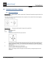
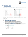
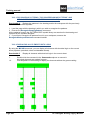
Draw the 3-pole connections.
Activate the Electrical ➤ Wire Connections ➤ 3 Wires command.
Click to select the starting point for the wire on the potential L1 vertically above the
connections of the first terminal (X2:4).
Click to select the second point for the wire on the top connection of the first terminal
(X2:4).
Three connections are drawn automatically: between the potential L1 and the first terminal
(X2:4), between the potential L2 and the second terminal (X2:5), and between the
potential L3 and the third terminal (X2:6).
They are automatically broken where the symbols are placed (for example, at the main
relay-contact).
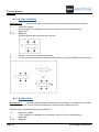
Now use the Electrical ➤ Wire Connections ➤ Orthogonal Wiring function to draw a 3wire connection between the potentials L1, L2 and L3 and the motor.
Activate the Electrical ➤ Wire Connections ➤ Orthogonal Wiring command.
Click to select the starting point for the wire on the potential L1 vertically above the
connection of the motor.
Click again to select the ending point on the first connection (U1) of the motor.
Four wires are automatically drawn to connect the motor to the potentials.
Now continue to draw multiple orthogonal wires proceeding as follows:
Click, for example, the connection between the potential L3 and the motor somewhere
below the contactor. Then click the connection 6 of the second contactor.
Similarly, click the connection 1 of the same contactor and then click the connection
between the potential L1 and the motor somewhere above the first contactor.
Right-click to exit the drawing mode.
C. Drawing the First Page of a Circuit Diagram
Training Manual
COPYRIGHT © 2013 IGE+XAO. All rights reserved
Hints
1. While you are moving the cursor, a dynamic visualization of the connection and contact points
appears, allowing you to see if the wires you are trying to draw are overlapping existing ones or
are violating symbols. In such case, drawing is restricted since SEE Electrical automatically
checks whether the desired connection is possible.
Exercise 3-8:
Draw the missing wire between the potential PE and the terminal X2:7. Change
the line style and the colour of the wire between the potential PE and the motor M2.
1.+
2.+
3.>
4.>
5.>
6.>
7.
8.
Use the Electrical ➤ Wire Connections ➤ 1 Wire command, as already described, to
draw the missing wire between the potential PE and the terminal X2:7.
Right-click the wire between the potential PE and the terminal X2:7 and select the
Properties pop-up command.
The wire properties appear in the Properties pane in the right part of the main SEE
Electrical window.
Penstyle
Select the line "Dash" style.
Pencolour
Select green colour.
The colour and the line style of the wire are changed dynamically on the screen.
Repeat the same operation for the wire between the terminal X2:7 and the motor.
Select the motor M2. Its properties appear in the Properties pane. Fill in "PE" in the field
for connection 03. Press the "Enter" key to validate.
Select the terminal X2:7 and, as described above, change its terminal number to PE via
the Properties pane.
You have completed Page 1 of the circuit diagram.
Exercise 3-9:
1.CA
2.CO
Save the workspace.
File
Save
Save frequently your workspaces. You can also click on the
C. Drawing the First Page of a Circuit Diagram
icon.
Page 25
Training manual
COPYRIGHT © 2013 IGE+XAO. All rights reserved
C.4. WORKING WITH A ZOOMED PART OF THE DRAWING
It is often necessary to zoom parts of the drawing.
Exercise 3-10:
Zooming the drawing through the Preview window.
Within the Preview window:
1.+
2.+
3+
4+
Click the first point of the rectangle outlining the area you want to zoom.
The rectangle is defined by two diagonally opposite points.
Click the second point of the rectangle opposite to the first one.
The selected area is zoomed.
You can move the zoomed area through the Preview window
Place the cursor on the grey rectangle that defines the zoomed area.
The cursor is displayed as a hand symbol.
Click and hold the left mouse button to move the rectangle.
To zoom out activate the Zoom Original command by pressing the F3 hot-key.
Exercise 3-11:
1.CA
2.CO
3.+
4.+
View
Zoom Window (Zoom panel)
Click the first point of the rectangle outlining the area you want to zoom.
The rectangle is defined by two diagonally opposite points.
Click the second point of the rectangle opposite to the first.
You can activate the Zoom Window command by pressing the F4 hot key.
Exercise 3-12:
1.CA
2.CO
3.+
Switch back to the general view of the circuit diagram.
View
Zoom Original (Zoom panel)
You can see the whole drawing again.
You can activate the Zoom Original command by pressing the F3 hot key.
Exercise 3-13:
1.CA
2.CO
Enlarge a part of the circuit diagram.
Moving the zoomed area.
View
Zoom Pan (Zoom panel)
The cursor appears as a hand.
Click the left mouse button and move the cursor to the desired position.
To zoom out activate the Zoom Original command by pressing the F3 hot key
Hint:
It is possible to zoom with a mouse wheel, pressing and holding down CTRL while scrolling the
mouse wheel upwards (enlarge) or downwards (decrease).
If you have a mouse wheel, press and hold it, then you can move the currently zoomed part of the
drawing.
Page 26
C. Drawing the First Page of a Circuit Diagram
Training Manual
COPYRIGHT © 2013 IGE+XAO. All rights reserved
D
DRAWING THE SECOND PAGE OF A CIRCUIT DIAGRAM
D.1. CREATING PAGE 2
Exercise 4-1:
1.CA
2.CO
3.>
4.#
5.>
6.>
7.>
Create page 2 of the workspace.
Home
New (Page panel)
If this function is not active, click the Circuit diagrams module in the Workspace Explorer
area, then click Home ➤ Page ➤ New again.
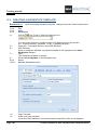
The Page information dialogue box appears.
Page description-line 01
Control gear
Page
Page number 2 is automatically suggested. Do not change it.
Page Created Date
The current date is displayed in this line.
Click OK to close the dialogue box.
SEE Electrical opens a new circuit diagram page.
Now, you can start drawing the second page of the circuit diagram.
D. Drawing the Second Page of a Circuit Diagram
Page 27
Training manual
COPYRIGHT © 2013 IGE+XAO. All rights reserved
D.2. DRAWING PAGE 2
In this chapter you will draw potentials L1 and N, some components and wires on page 2.
Exercise 4-2:
1.CA
2.CO
3.>
4.#
5.>
Draw potential L1.
Electrical
Top (Potential panel)
Product (-)
L1
Type the name of the potential.
OK
Close the dialogue.
Left to the potential, the cross-reference to the potential on page 1 appears automatically.
Exercise 4-3:
colour.
Draw potential N. Change the line style before drawing: select "Dash" and blue
1.
In the Styles panel of the Draw category, click the small arrow in the
Select "Dash". Now you can draw with a dashed line.
2.
In the Styles panel of the Draw category, click the small arrow in the
Choose "Blue". Now you can draw with blue colour.
Page 28
icon.
icon.
D. Drawing the Second Page of a Circuit Diagram
Training Manual
COPYRIGHT © 2013 IGE+XAO. All rights reserved
Exercise 4-4:
1.CA
2.CO
3.>
4.#
5.>
Electrical
Bottom (Potential panel)
Product (-)
N
OK
The dialogue box closes.
Change the line style again - choose "Solid" line and black colour.
In the Style toolbar, change the line style - choose "Solid" line.
In the Style toolbar, change the colour - choose black.
6.
7.
Exercise 4-5:
1.
2.
Draw the potential N.
Insert the relay symbol.
▪
Insert the first relay.
▪
Select the "EN61346-2UK" symbol database.
Move the cursor into the Symbols area.
Double-click the "EN61346-2UK" symbol database or click the plus sign to the left of the
symbol folder
.
The symbol database opens and the symbol folders are displayed.
Double-click the Relay coils folder to open it.
If the desired symbol folder is not visible, scroll down the symbol tree to find it.
D. Drawing the Second Page of a Circuit Diagram
Page 29
Training manual
COPYRIGHT © 2013 IGE+XAO. All rights reserved
3.
4.
5.+
Select the 1-pole component.
Move the cursor to the drawing.
The symbol appears attached to the cursor.
"Drop" the symbol at the desired position in the drawing sheet, in this case column 2.
The contact cross appears under the relay.
Hint:
You can move the contact cross to another position, if desired.
Exercise 4-6:
1.
2.
folder.
Page 30
Insert a one-pole Switchgear symbol.
Move the cursor to the Symbols area.
Close the "Relay coils" symbol folder by clicking the minus sign to the left of the symbol
D. Drawing the Second Page of a Circuit Diagram
Training Manual
COPYRIGHT © 2013 IGE+XAO. All rights reserved
3.
4.
5.
6.+
7.>
8.#
9.>
10.#
11.>
Double-click the "Switchgear, one pole" symbol folder to open it.
Click the NO turn detent component.
Move the cursor to the drawing area.
The symbol appears attached to the cursor.
"Drop" the symbol at the desired position in the drawing sheet, in this case column 2.
Double-click the symbol. The Component Properties dialogue appears.
Connection 00
13
Type the contact number.
Connection 01
14
Type the contact number.
OK
Close the dialogue box.
Hint
You can rotate a symbol by 90 degrees or more before inserting it.
▪ Press the "+" or "-" key on the numerical key board while the symbol is attached to the cursor.
The symbol is rotated 90 degrees clockwise or counter clockwise.
If you press the respective key once again, the symbol is rotated by another 90 degrees.
You can rotate the symbol with the help of the X or Z keyboard keys.
Exercise 4-7:
Insert a Relay-contact NO symbol.
D. Drawing the Second Page of a Circuit Diagram
Page 31
Training manual
COPYRIGHT © 2013 IGE+XAO. All rights reserved
1.
2.
3.
4.
5.
6.+
7.>
8.#
9.>
10.#
11.>
12.#
13.>
Move the cursor to the Symbols tree.
Close the "Switchgear one pole" symbol folder by clicking the minus sign left to the folder
name.
Double-click the "Relay-contacts NO" symbol folder.
Click the "1-pole NO" symbol
Move the cursor to the drawing area.
The symbol appears attached to the cursor.
"Drop" the symbol at the desired position in the drawing sheet, in this case column 2.
Product (-)
Type the name of the component which the contact must be assigned to.
1Q2
Click the
button in the "Product (-)" field.
The Function Location Product window appears listing the available contacts.
Choose the contact from this list.
Connection 00
13
Type the contact number.
Connection 01
14
Type the contact number.
OK
Close the dialogue box.
Hint:
You can also select symbols by using the graphical overview.
▪ Right-click the symbol folder within the Symbols tree, where the symbol is located - in our
example Relay-contacts NO.
▪ Select the Graphical Overview pop-up command.
Page 32
D. Drawing the Second Page of a Circuit Diagram
Training Manual
COPYRIGHT © 2013 IGE+XAO. All rights reserved
▪ Scroll forward or backward through the symbols by clicking the "<<Backward" and the
"Forward>>" buttons.
▪ Click a symbol to select it.
D. Drawing the Second Page of a Circuit Diagram
Page 33
Training manual
COPYRIGHT © 2013 IGE+XAO. All rights reserved
Exercise 4-8:
1.
2.
3.
4.
5.
6.+
7.>
8.#
9.>
10.#
11.>
12.#
13.>
14.#
Page 34
Insert the terminals.
Move the cursor to the Symbols tree.
Close the "Relay-contacts NO" symbol folder by clicking the minus sign to the left of the
folder name.
Double-click the "Terminals" symbol folder.
Click the 1 terminal 90° vertical component.
Move the cursor to the drawing area.
The symbol appears attached to the cursor.
"Drop" the symbol at the desired position in the drawing sheet, in this case above the
switch gear symbol in column 2.
The terminal name is asked.
Product (-)
X3
Type in the terminal name.
Terminal number
1
Fill in terminal number 1.
Terminal Index
1
The terminal index is used for sorting the terminals in the terminals list in order to insert
terminals PE or N in the right place in the terminals list.
Type
039061
Type in the type of the terminal.
D. Drawing the Second Page of a Circuit Diagram
Training Manual
COPYRIGHT © 2013 IGE+XAO. All rights reserved
15.>
OK
Close the dialogue box.
16.+
Place the next terminal under the switchgear symbol in column 2.
The terminal name is asked.
Product (-)
X3
The component name, terminal number and index are suggested. Accept them.
Type
039061
Fill in the type of the terminal.
OK
The box closes.
Right-click to exit the insertion mode.
17.>
18.#
19.>
20.#
21.>
Exercise 4-9:
1.CA
2.CO
3.+
4.+
5.
Draw the wire.
Electrical
1 Wire (Wires Connections panel)
Select the starting point for the wire on the potential L1 above the symbols.
Select the second point for the wire on the potential N below the symbols.
The wire is drawn and automatically broken where the symbols are inserted.
Right-click to exit drawing mode.
D. Drawing the Second Page of a Circuit Diagram
Page 35
Training manual
COPYRIGHT © 2013 IGE+XAO. All rights reserved
Exercise 4-10:
potential N.
Change the line style and the colour of the wire between the relay coil and the
1.+
Right-click the wire and select the Properties pop-up command.
The wire properties appear in the Properties pane in the right part of the main SEE Electrical
window.
2.>
Penstyle
3.>
Select the line "Dash" style.
4.>
Pencolour
5.>
Select blue colour.
The colour and the line style of the wire are changed dynamically on the screen.
Page 36
D. Drawing the Second Page of a Circuit Diagram
Training Manual
COPYRIGHT © 2013 IGE+XAO. All rights reserved
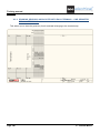
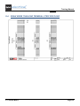
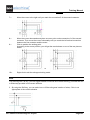
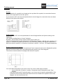
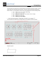
D.3. COPYING EXISTING ELEMENTS ON PAGE 2
Exercise 4-11:
Copy the drawn column.
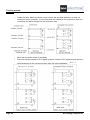
1.+ The Edit ➤ Select ➤ Normal function is active in case the cursor appears as an arrow
.
You can a single element or all of the symbols to be copied with a frame. The frame is defined as a
rectangle by marking two opposite corners.
In this exercise you will use a frame.
Two ways exist for selecting part of the drawing by a frame:
If you wish to process only elements that are located entirely within the area, move the cursor from
left to right:
The cursor graphic becomes:
If you wish to process all objects that are even partly included in the area, move the cursor from the
right to the left:
The cursor graphic becomes:
D. Drawing the Second Page of a Circuit Diagram
Page 37
Training manual
COPYRIGHT © 2013 IGE+XAO. All rights reserved
Hint:
If you wish to select elements in drawings with a lot of content, it is possible that you cannot place the
first corner point of the frame, since directly an element is selected.
The erroneous selection of an individual element can be avoided as follows:
▪ Press the W key on the keyboard and keep it pressed, while you click the first corner point of
the rectangle using the left mouse button.
2.+
3.+
4.
5.+
6.>
7.>
8.>
9.#
10.>
Press the left mouse button to define the first corner of the frame left above in the just now
drawn column 2.
The symbols are selected, if they are located completely in the frame.
Hold down the left mouse button while dragging to define the second corner in the next
step.
Select the second frame corner in the right bottom of the just now drawn column. All
selected components and wires have been highlighted.
After you have selected the column, place the cursor near the top left node. This point has
to be placed after copying. Press and hold down CTRL, press the left mouse button, and
move the mouse. A copy of the column has been created and can be inserted in the
desired position - in column 3. (If you do not press the CTRL key, the selected
components are moved.)
Insert the copy in column 3 and release the CTRL key.
The sequence of the dialogue boxes for the components depends on the sequence, in
which the components have been inserted or moved.
The terminal name is asked.
Product (-)
X3 is suggested by default. Type in terminal number 3 and terminal index 3, if they do not
appear automatically.
OK
The name for the normally open contact is asked.
Product (-)
Fill in the name of the contact NO.
K4
OK
Close the dialogue box.
Exercise 4-12:
Deselect all the selected components.
You can unselect all components by clicking at a position on the page where no object is located.
1.CA
2.CO
Page 38
General
Deselect All (Select panel)
D. Drawing the Second Page of a Circuit Diagram
Training Manual
COPYRIGHT © 2013 IGE+XAO. All rights reserved
Exercise 4-13:
1.
2.
3.
4.
5.+
6.>
7.#
8.>
9.#
10.>
11.#
12.>
13.
Insert the "1-pole NC" symbol. Place it on the existing wire in column 3.
Move the cursor to the Symbols tree.
Double-click the "Relay-contacts NC" symbol folder to open it.
Click the "1-pole NC" symbol.
Move the cursor to the drawing area.
The symbol appears attached to the cursor.
"Drop" the symbol at the desired position in the drawing sheet, in this case above the
relay coil in column 3.
The connection has been broken.
The dialogue box for the 1-pole NC relay contact appears.
Product (-)
K4
Connection 00
21
Insert contact number.
Connection 01
22
Insert contact number.
OK
Right-click to exit insertion mode.
D. Drawing the Second Page of a Circuit Diagram
Page 39
Training manual
COPYRIGHT © 2013 IGE+XAO. All rights reserved
Exercise 4-14:
1.+
3).
2.+
3.
4.+
5.>
6.>
Page 40
Copy components and wires needed for column 4.
Define the first frame point so that the top terminal is located within the frame (in column
Define the second frame point right below the group in column 3. All of the components
within the frame are highlighted.
After you have selected the required components and wires, click onto the top connection
of the relay coil. Press and hold down the CTRL key, press the left mouse button and
move the mouse. "Drag" the copy of the group to the desired place in column 4.
"Drop" the copy and release the CTRL key.
The dialogue boxes for the terminals and the contact appear.
The sequence of the dialogue boxes for the components depends on the sequence in
which the components have been inserted or moved.
The terminal name is asked.
Product (-)
X3 is suggested by default.
Insert the terminal number 5.
Insert the same value for the terminal index.
For the standard and higher levels of SEE Electrical, at the end of the Terminal number
line and Terminal Index line, the icon
appears. This function allows always finding
out the highest value for terminal number + 1 in the terminal strip, the same function is
available for the terminal index.
OK
The name for the 1-pole NC contact is asked.
D. Drawing the Second Page of a Circuit Diagram
Training Manual
COPYRIGHT © 2013 IGE+XAO. All rights reserved
7.>
8.>
9.>
Product (-) K4
Click the
button in the "Product (-)" field.
The Function Location Product window appears listing the available relay coils.
K3
Select the desired relay coil from the list.
OK
Exercise 4-15:
1.+
Click the left mouse button in an empty area of the window.
Exercise 4-16:
1.CA
2.CO
3.+
4.+
5.+
6.
Deselect all of the selected components.
Draw the missing wire.
Electrical
1 Wire (Wires Connections panel)
Place the first point of the wire on the existing vertical connection.
Place the corner point of the wire.
Place the end point of the wire onto the terminal.
Right-click to exit wire insertion mode.
D. Drawing the Second Page of a Circuit Diagram
Page 41
Training manual
COPYRIGHT © 2013 IGE+XAO. All rights reserved
Exercise 4-17:
column.
Draw the first missing column and then copy it to create the second missing
Insert again terminals, a normally open contact, and a lamp from the symbol database. You can find
the lamp in the Lamps folder. Right-click to exit insertion mode.
For the 1-pole NO relay-contact, choose the component name K2 from the list of relay coils and
type in the numbers 13 and 14. The terminals receive the suggested names and the type 036091.
Draw the wire by executing the Electrical ➤ Wire Connections ➤ 1 Wire command. Right-click to
exit wire insertion mode.
▪
Select the wire between the terminal and the potential N to change its line style and
colour.
You can copy the first new column to create the second by using a frame.
▪ Accept the suggested names for the terminals and fill in K3 as a name for the normally
open contact.
Page 42
D. Drawing the Second Page of a Circuit Diagram
Training Manual
COPYRIGHT © 2013 IGE+XAO. All rights reserved
Exercise 4-18:
Copy the third normally open contact.
1.+
Click the contact that you want to copy. If the cursor does not appear as an arrow, click
General ➤ Select ➤ Normal to activate the selection mode.
The contact has been selected.
2.
Press and hold down the CTRL key, press the left mouse button and "drag" the contact to
the desired position in column 8.
3.
"Drop" the copy there.
The dialogue box for the contact name appears.
4.>
Product (-)
5.>
K4
Choose the name from the list in the Function Location Product window.
6.>
OK
Close the dialogue box.
Deselect the contact.
7. Click anywhere within the empty area of the drawing.
Hint
You can insert multiple copies of the copied object.
▪ Select the object you wish to copy.
▪ Execute the Copy pop-up command.
▪ Select the Paste pop-up command.
D. Drawing the Second Page of a Circuit Diagram
Page 43
Training manual
COPYRIGHT © 2013 IGE+XAO. All rights reserved
▪ Press the number corresponding to the number of copies needed before you click to position
the first copy of the object.
▪ Click to position the first copy at the desired distance from the original object. The next copy
appears at the same distance, but in the next column. The same happens with the other copies.
If you type 0, you can create more than nine copies and define the distance between them.
Please note that this function is not available for the US version.
Exercise 4-19:
1.CA
2.CO
3.+
4.+
5.+
6.
Electrical
1 Wire (Wires Connections panel)
Select the starting point for the wire on the available wire between the NO contact K3 and
the terminal.
Select the corner point for the wire.
Select the end point for the wire on the potential L1.
Right-click to exit the drawing mode.
Exercise 4-21:
1.CA
2.CO
Draw the missing wire.
Save the workspace.
File
Save
Save frequently your workspaces. You can also click on the
Page 44
icon.
D. Drawing the Second Page of a Circuit Diagram
Training Manual
COPYRIGHT © 2013 IGE+XAO. All rights reserved
E
DRAWING CABLES
Exercise 5-1:
1.CA
2.CO
Draw cables W1 and W2 on page 1.
Electrical
Cable (Cable panel)
Note
In case you have selected the appropriate setting in the Cables tab of the Circuit Diagram
Properties window, when you execute the Electrical ➤ Cable ➤ Cable command, a dialogue
appears allowing you to insert a cable with previously defined symbols for start, middle and end of
the graphics. These user-defined cables are defined via the Cable Setup button in the Cables tab of
the Circuit Diagrams Properties window. If you choose an user-defined cable from the dialogue,
the cable will be inserted as previously defined.
If you use user defined cable symbols, the middle symbol will be automatically enlarged to cover any
gap between the wires.
3.+
4.+
Select a starting point for the cable.
Select the end point of the cable.
The Component Properties dialogue for the cable appears.
E. Drawing Cables
Page 45
Training manual
COPYRIGHT © 2013 IGE+XAO. All rights reserved
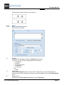
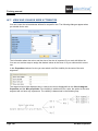
5.#
Insert the cable information as desired.
Fill in the information in the dialogue box as shown below.
6.>
7.#
8.>
9.#
Product (-)
W1
Type
U-1000 R2V 4G2,5²
The cable core numbers and colours are filled in automatically according to the selected
cable type.
Tick the check boxes in the Show column to define the data you wish to display on the
drawing.
OK
Draw the cable W2 by using the same approach.
10.>
Page 46
E. Drawing Cables
Training Manual
COPYRIGHT © 2013 IGE+XAO. All rights reserved
Fill in the cable information as shown below and click OK to close the dialogue box.
Note
If you want to toggle on/off the visibility for all cable core texts, you can press the SHIFT key on your
keyboard and then check/uncheck the visibility for the first cable-core text. The texts for the other
cable cores are automatically switched on/off.
E. Drawing Cables
Page 47
Training manual
COPYRIGHT © 2013 IGE+XAO. All rights reserved
F
ADDITIONAL PROCESSING OF CIRCUIT DIAGRAMS
Exercise 6-1:
1.+
Insert description for the two lamps on page 2.
Double-click the left lamp.
The Component Properties dialogue appears where you can add a description text.
Description
Fan runs
OK
Close the dialogue box.
Double-click the second lamp.
Description
Conveyor runs
OK
2.>
3.#
4.>
5.+
6.>
7.#
8.>
Exercise 6-2:
Name the contactors on page 1.
▪
Double-click page 1 in the Workspace pane to open it. 1. You can also click the
or press the Page Up key on the keyboard to go to the previous page.
▪ Double-click the first contactor on column 2.
Its Component properties dialogue box appears.
1.>
2.#
3.>
4.>
5.#
Page 48
icon
Product (-)
K2
Click the
button in the "Product (-)" field.
The Function Location Product window appears listing the available contacts.
Choose the K2 relay coil from this list.
OK
Close the dialogue.
Double-click the second contactor on column 4.
Its Component properties dialogue box appears.
Product (-)
K3
Click the
button in the "Product (-)" field.
F. Additional Processing of Circuit Diagrams
Training Manual
COPYRIGHT © 2013 IGE+XAO. All rights reserved
The Function Location Product window appears listing the available contacts.
Choose the K3 relay coil from this list.
6.>
7.>
8.#
9.>
OK
Close the dialogue.
Double-click the third contactor on column 5.
Its Component properties dialogue box appears.
Product (-)
K4
Click the
button in the "Product (-)" field.
The Function Location Product window appears listing the available contacts.
Choose the K4 relay coil from this list.
OK
Close the dialogue.
The cross references appear automatically under the contactors.
Hint
You can navigate between components and pages by clicking the cross-reference symbols. The
corresponding page is open and the component is shown by a red pin.
Exercise 6-3:
Look at the potentials on page 1. At the potentials L1 and N, cross-references to
page 2 have been created.
Exercise 6-4:
Switch to page 2. Look at the page. At the relay coils, cross-references to the
contacts on page 1 have been created.
1.
To switch to the next page, click on the icon
Exercise 6-5:
1.CA
2.CO
or press Page Down on the keyboard.
Save the workspace.
File
Save
F. Additional Processing of Circuit Diagrams
Page 49
Training manual
COPYRIGHT © 2013 IGE+XAO. All rights reserved
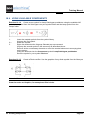
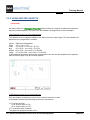
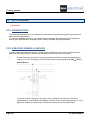
F.1. USING CROSS-REFERENCE SYMBOLS
If a wire cannot be drawn on the same page, symbols for cross-references are used. Cross-reference
symbols are available in the References folder of the EN61346-2UK symbol database. Only two
cross-references may receive one and the same name because a definite reference is required. The
look of the cross-reference symbols is not important. The connection of two cross-reference symbols
is possible via the component name.
Exercise 6-6:
Insert two cross-references in your example project.
▪
▪
Switch to page 1.
Open one symbol library EN61346-2UK. Open the References symbol folder and choose
"Reference (right)".
▪ Insert it and type the component name, for example V1.
▪ Switch to page 2. Select the "Reference (left)" symbol from the symbol libraries EN613462UK.
▪ Place it and type the name V1 again.
At both cross-references, a back-reference to the corresponding reference is created
automatically.
You can generate the cross-reference symbols using the Electrical ➤ Wire connections ➤
1 Wire command.
To insert cross-reference symbols while drawing a wire, double-click at the end of the wire.
The cross-reference symbol appears automatically.
Exercise 6-7:
A cross-reference can also be used for the Power supply, if you do not work with
Wires list and Wiring list. If you do so, use potential lines for the power supply.
The potentials on the next pages are created via the functions for drawing a potential.
Page 50
F. Additional Processing of Circuit Diagrams
Training Manual
COPYRIGHT © 2013 IGE+XAO. All rights reserved
Or
Exercise 6-9:
1.CA
2.CO
Save the workspace.
File
Save
F. Additional Processing of Circuit Diagrams
Page 51
Training manual
COPYRIGHT © 2013 IGE+XAO. All rights reserved
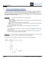
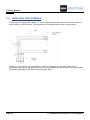
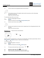
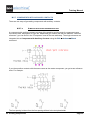
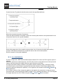
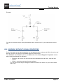
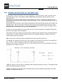
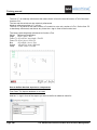
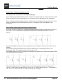
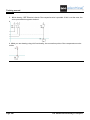
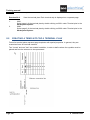
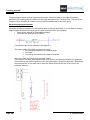
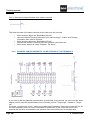
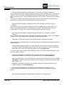
F.2. USING INFO TEXT SYMBOLS
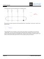
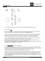
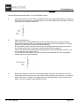
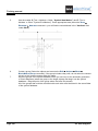
If wires begin or end as shown below, i.e. if your responsibility breaks at the end of a wire, this wire
has no target for SEE Electrical. The terminals of the terminal strip X0 have no target either.
However, if you insert an info text symbol (it consists of graphics, a connection point, and a
component name) at the end of the wire, the wire, and consequently the terminal, has a target again.
Info texts are available in the EN61346-2UK symbol library.
Page 52
F. Additional Processing of Circuit Diagrams
Training Manual
COPYRIGHT © 2013 IGE+XAO. All rights reserved
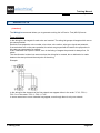
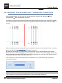
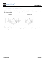
F.3. PAGE INDEX
If an installation has just been built, it is often necessary to add pages in order to have additional
circuit parts in the project. If a page numbering for the component names is used, then the names of
the components which are already installed must not be changed.
The page index allows inserting pages without changing the numbers of the existing ones.
Exercise 6-9:
▪
1.>
2.#
3.>
4.#
5.>
Insert page 1a in the workspace.
Create a new page using the same approach as for the creation of page 2.
Page
Change the page number.
1
Index
a
Type in the page index.
OK
The page has been created.
F. Additional Processing of Circuit Diagrams
Page 53
Training manual
COPYRIGHT © 2013 IGE+XAO. All rights reserved
Hint:
Place a symbol of a lamp on page 1a. If the workspace is created using Page Number, it is
automatically named 1aP0. When you draw the potential L1 on page 1a, the cross-references on
pages 1 and 2 will be updated. The same happens to the cross references for coils and contacts.
They will also be updated using the information of the page index.
Exercise 6-10:
1.CA
2.CO
Page 54
Save the workspace.
File
Save
F. Additional Processing of Circuit Diagrams
Training Manual
COPYRIGHT © 2013 IGE+XAO. All rights reserved
F.4. TEXTS
Exercise 6-11:
You can insert comment texts in a page. Please insert the texts "Motor control 1"
and "Motor control 2" in page 2.
1.CA
2.CO
Draw
New Text (Elements panel)
You can click the
icon, too (the
allows you to edit existing texts).
3.+
4.#
icon allows you to create a new text, the
icon
Move the cursor into the "Text" field.
Motor control 1
Type in the text.
F. Additional Processing of Circuit Diagrams
Page 55
Training manual
COPYRIGHT © 2013 IGE+XAO. All rights reserved
5.>
Tick the "Show advanced properties" check box and select the desired text attributes,
such as size, highlight colour and adjustment (Left justified, or Centre justified).
6.+
Insert the text in the drawing by clicking at the desired position.
The Text dialogue box remains open.
Move the cursor into the "Text" field again.
Change the existing text or type in a new text, place the text in the drawing, etc.
Click the
button to close the Text dialogue box.
7.+
8.
9.>
Exercise 6-12:
Change the text you just inserted.
1.CA
2.CO
Edit
Edit Text (Text panel)
3.M
You can also click the
icon.
Click the text you want to change.
4.+
Move the cursor into the "Text" field.
Page 56
F. Additional Processing of Circuit Diagrams
Training Manual
COPYRIGHT © 2013 IGE+XAO. All rights reserved
5.#
<Text>
Change the text "Motor control 1" to "Motor 1".
The change can be seen directly in the drawing.
6.>
If you want, tick the "Show advanced properties" check box and change the desired text
attributes, such as size, highlight colour and adjustment (Left justified, or Centre justified).
7.+
8.+
9.
Click the next text you want to change: "Motor control 2" to "Motor 2" for example.
The Text dialogue box remains open.
Move the cursor into the "Text" field again.
Change the existing text etc.
10.>
Click the
button to close the Text dialogue box.
F. Additional Processing of Circuit Diagrams
Page 57
Training manual
COPYRIGHT © 2013 IGE+XAO. All rights reserved
G
HYPERLINKS
G.1. MANAGING THE HYPERLINKS
The commands give you the possibility to manage hyperlinks (web addresses or files) within the
different pages of the project.
You can add a hyperlink to each graphical object present within the SEE Electrical drawings.
It is possible to view which objects have a hyperlink through the Hyperlink command in the View
category.
If you add a hyperlink to a symbol, the link will be stored in the Symbols library together with the
symbol.
All picture files (BMP, JPG, TIFF, etc.), PDF files or MS Office files can be linked to an object.
Activate the Define command and paste the link from your browser (if it is a web address) or the path
to the file you want to link to the object into the field.
You can use the Define command in case you want to modify the hyperlink.
Click on the hyperlink and activate the Open command in order to load the link.
If you want to delete a hyperlink, click it and activate the Delete command.
Page 58
G. Hyperlinks
Training Manual
COPYRIGHT © 2013 IGE+XAO. All rights reserved
H
REDLINING
Redlining objects are graphical remarks inserted on the drawings. They can also be created in the
Viewer software.
Redlining objects are stored separately in the database so that the original drawing is not changed or
damaged.
All redlining objects are drawn in red and are saved in layer 1. They consist of a callout graphics and
a callout text, which are processed in a single operation.
Exercise 7-1:
▪
1.CA
2.CO
3.+
4.+
5.+
6.+
7#
8.+
9.+
Draw a callout around the first motor on page 1.
Open page 1 of the workspace.
Redlining
Cloud (Draw Callouts panel)
Click the first point of the cloud outlining the area you want to mark.
The cloud is defined by two diagonally opposite points.
Click the second point of the cloud opposite to the first.
Click once again to mark the point where the callout text is to be positioned.
Type in the desired callout text, in our example "Add information about power".
Press CTRL+ENTER to start a new line of the text.
Click OK to close the window.
Click the left mouse button or press the Enter key to finish drawing
The redlining is displayed on the page:
Right-click to exit callout drawing mode.
Exercise 7-2: Edit and move the inserted callout.
Special commands are available to allow you to edit and move callouts. The conventional commands
cannot be used in this case because the callouts are also available in the Viewer software.
1.CA
2.CO
3.+
H. Redlining
Redlining
Edit Text Callouts (Edit Callouts panel)
Click the callout's text in the drawing to select it.
The Text window appears. You can edit the text.
Page 59
Training manual
COPYRIGHT © 2013 IGE+XAO. All rights reserved
4.+
5.CA
6.CO
7.CO
8.+
9.
Click the
button to apply the changes.
Redlining
Select Callouts (Select Callouts panel)
Move Callouts (Edit Callouts panel)
Click the callout you want to move.
Click on the new position of the callout.
Exercise 7-3: Select and delete the callout you just inserted.
Special commands are available to allow you to select and delete callouts. The conventional
commands cannot be used in this case because the callouts are also available in the Viewer
software.
1.CA
2.CO
3.+
4.CA
5.CO
Page 60
Redlining
Select Callouts (Select Callouts panel)
The cursor changes to
.
Click the callout in the drawing to select it.
You can select several callouts by holding down the Shift or the CTRL keys during the
selection (standard Windows procedure).
Redlining
Delete Callouts (Select Callouts panel)
The callouts are deleted.
Right-click to exit the callout deletion mode.
H. Redlining
Training Manual
COPYRIGHT © 2013 IGE+XAO. All rights reserved
I
PRINTING
I.1.
PRINT
Exercise 8-1:
1.CA
2.CO
3.CO
After the project is completed, it can be printed.
File
Print
Print Document
A print preview is available for single pages of the project. This function can be accessed by clicking
the Print Preview button in the Print dialogue or by executing the File ➤ Print ➤ Print Preview
command.
I. Printing
Page 61
Training manual
COPYRIGHT © 2013 IGE+XAO. All rights reserved
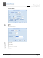
Exercise 8-2: Print Preview
1.CA
2.CO
File
Print ➤ Print Preview
A print preview of the currently active page appears.
3.>
4.>
Click the
icon to zoom the preview.
Click the Close button to exit the print preview
or
Press the ESC key on the keyboard.
Page 62
I. Printing
Training Manual
COPYRIGHT © 2013 IGE+XAO. All rights reserved
J
DATABASE LISTS
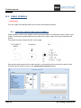
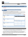
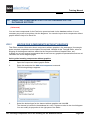
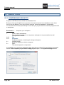
Exercise 9-1:
▪
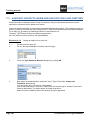
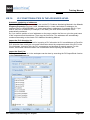
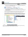
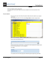
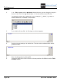
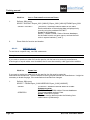
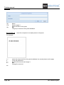
View the workspace database lists.
Switch from the Symbols view to the Workspace view by clicking the Workspace tab.
The Workspace tree opens. According to the level (basic, standard, or advanced), different database
lists are displayed.
▪
Select the desired list, for example View, Products.
J. Database Lists
Page 63
Training manual
COPYRIGHT © 2013 IGE+XAO. All rights reserved
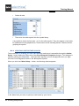
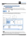
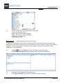
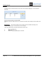
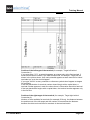
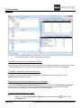
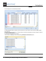
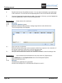
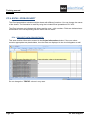
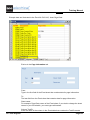
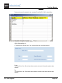
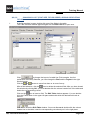
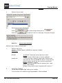
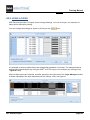
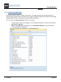
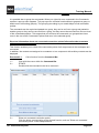
1.
View, Products
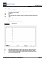
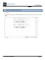
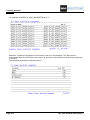
Double-click the list to display its contents in the right pane:
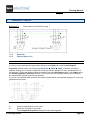
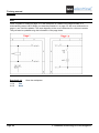
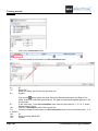
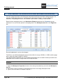
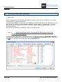
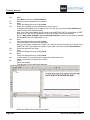
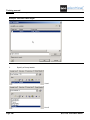
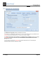
Exercise 9-2:
1.>
2.M
3.>
4.M
5.#
6.>
7.M
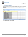
Select the "Product" column
Click the right mouse button.
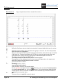
Select the Sort descending on row pop-up command.
The components will be sorted in descending order and the components on page 2 (i.e.
with 2 as the first character in their names) will be displayed before the components on
page 1.
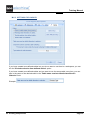
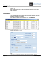
Select the "Product" column again.
Click the right mouse button.
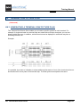
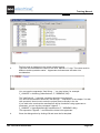
Click the Set Filter On -> Product? pop-up command.
*K*
Type in the Filter-Value.
If you are searching for one specific component, you can type its complete name. You
may use the wildcards characters ? and * for filtering according to any single character (?)
or more characters (*).
If you press ENTER, only the records that satisfy the filter condition will be displayed.
Select the "Product "column again.
Click the right mouse button.
Select the Remove Filter/Sort pop-up command.
All of the records are displayed again.
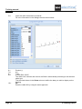
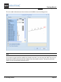
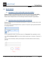
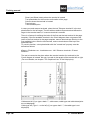
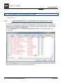
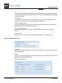
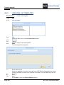
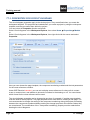
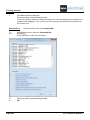
Exercise 9-3:
1.>
2.M
3.#
4.>
5.M
Page 64
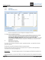
You can sort or filter the information in the list.
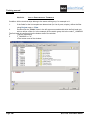
Creating, storing and loading filters and sorting.
Select the "Product" column
Click the right mouse button.
Click the Set Filter On -> Product? pop-up command.
*K*
Type in the Filter-Value.
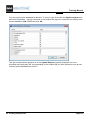
Select the "Product "column again.
Click the right mouse button.
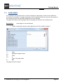
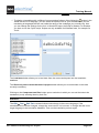
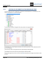
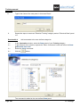
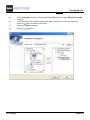
Select the Load Filter/Sort from File pop-up command.
J. Database Lists
Training Manual
COPYRIGHT © 2013 IGE+XAO. All rights reserved
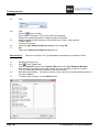
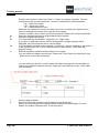
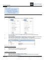
Select the desired filter/sorting fro the drop-down list in the window that appears:
6.>
Click OK.
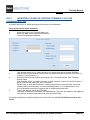
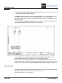
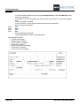
Exercise 9-4:
You can save the lists in other files, for example in MS-Excel or MS-Word files.
1.
Launch MS-Excel or MS-Word.
2..>
Click the top left field in the database list as shown above.
The database list is selected.
CTRL + C
The selected area has been copied.
Paste the copied data area within MS-Excel or MS-Word by clicking CTRL + V.
3.#
4.
Exercise 9-5:
1.CA
2.CO
Save the workspace.
File
Save
J. Database Lists
Page 65
Training manual
COPYRIGHT © 2013 IGE+XAO. All rights reserved
K
GRAPHICAL LISTS
K.1. GENERATING A GRAPHICAL LIST
The graphical lists allow filling the project information in forms.
Exercise 10-1:
1.
Create a graphical product list for the workspace.
Expand the Graphical Lists node in the Workspace tree.
According to the level and the language version of the software, different Graphical Lists
are available.
2.
3.CO
Page 66
Select the Products graphical list and click the right mouse button.
Generate
The graphical list has been generated.
K. Graphical Lists
Training Manual
COPYRIGHT © 2013 IGE+XAO. All rights reserved
4.
0001
Click the plus + sign in front of Products in the Workspace Explorer and open the
graphical list by double-clicking 0001.
Exercise 10-2:
lists afterwards.
Generate other graphical lists using the same approach. Look at the graphical
Terminal matrix and Wiring can be generated in SEE Electrical standard and advanced.
Terminal plan, Terminal row picture plan and Multicores can be generated only in SEE Electrical
advanced.
Products Assembly can be generated only in SEE Electrical advanced.
Exercise 10-3:
1.CA
Save the workspace.
File ➤ Save
K. Graphical Lists
Page 67
Training manual
COPYRIGHT © 2013 IGE+XAO. All rights reserved
K.2. DEFINE PAGE TEXTS PEMANENTLY
The Defaults button is available in the List Properties dialogue for all lists.
You can define the texts that will appear in the text attributes of the defined template.
The Terminal Matrix, Terminal Plan, Terminal Row Picture use the "Page Description 01" texts.
K.3. GENERATING ALL DESIRED GRAPHICAL LISTS IN ONE STEP
Within SEE Electrical, you can generate all desired graphical lists in a single operation.
If you possess the Basic or Standard levels of SEE Electrical, you need specific page templates in
order to generate multiple graphical lists in one step.
If you possess the Advanced level of the software, a specific functionality is available allowing you to
generate the lists.
For further details on how to do this, see chapter Creating Templates for Graphical Lists.
Page 68
K. Graphical Lists
Training Manual
COPYRIGHT © 2013 IGE+XAO. All rights reserved
L
INSERTING OTHER DOCUMENTS
You can insert other documents into the workspace, such as WinWord-files or Excel-spreadsheets.
The kind of these documents depends on the Windows programs installed on your computer and
supporting the ActiveX technology. When you wish to view such a document, the respective program
will be activated.
Exercise 11-1:
Insert a document from another Windows application, which supports the ActiveX
technology, as follows:
1.
Select Other documents in the Workspace tree.
2.CA
3.CO
Home
New (Page panel)
SEE Electrical opens the Page information dialogue box.
Page Description-line 01
Other data
Page
Page number 1 is suggested automatically. Do not change it.
Page Created Date
The current date is suggested.
You may fill in additional information, if desired.
OK
The dialogue box closes.
The Insert Object dialogue box appears, allowing you to choose the other document to
be inserted. The dialogue box contains the Windows applications installed on your
computer which support the ActiveX technology.
Choose one of the displayed applications.
OK
The dialogue box closes. The functions of the selected application are now available for
editing the document.
Edit your document.
4.>
5.#
6.>
7.>
8.>
9.>
10.>
11.
Exercise 11-2:
1.CA
2.CO
Save the workspace.
File
Save
L. Inserting Other Documents
Page 69
Training manual
COPYRIGHT © 2013 IGE+XAO. All rights reserved
M
CREATING COMPONENTS
Components for circuit diagrams must be created in accordance with explicit rules in order to identify
the connections and to manage the components properly (for example, for a contact to be listed in
the Products list).
M.1. CREATING A COMPONENT
Using the example of the black box, we illustrate how components are created.
Hints:
1. It is recommended to set a 5 mm grid for the drawing of components for circuit diagrams. You
can draw new components using a grid of 5mm, 2,5 mm or less. Make sure that the created
symbol fits into a 5 mm grid, i.e. the connections have to end at the grid points. You can set
the grid via the Styles panel. A function is available in the View category allowing you to
toggle the visibility of the grid.
2. The line width should be controlled. The line width for drawing connections must be identical
with the line width for drawing wires. Most of the symbols in the included symbol libraries are
drawn using a 0,25mm line width.
Exercise 12-1:
Draw the graphics for the component. You must use only the ordinary drawing
functions, such as Draw Line, Rectangle, Circle etc., but not wires.
▪
▪
1.CA
2.CO
3.+
4.+
5.
3.
Page 70
Create a new page in your workspace.
Construct the graphics.
Draw
Rectangle (Elements panel)
Draw a rectangle with width 20 mm and height 5 mm. This is possible on the default grid
of 5mm. The width and height of the rectangle are shown in the Status bar beneath the
drawing area as you draw.
Click to define the left top corner point for the rectangle.
Click again to mark the right bottom corner point for the rectangle.
Right-click to quit the drawing mode.
or
Click to define the left top corner point for the rectangle.
M. Creating Components
Training Manual
COPYRIGHT © 2013 IGE+XAO. All rights reserved
4.
Keep the left mouse button pressed and move the cursor to the right bottom corner point
of the rectangle.
8.
Release the mouse button.
9.CA
Draw
10.CO
Line (Elements panel)
Draw two connection lines above and below the rectangle. These connection lines should
be 5 mm long. The length of the lines is shown beneath the drawing area as you draw.
11.+
Click the starting point of the line.
12.+
Click the second line point.
13.
Right-click to finish drawing the line, do not draw a polygon.
Afterwards, you can draw the next line.
14.+
Click the starting point.
15.+
Click the second point.
etc.
Right-click to finish drawing the last line, do not draw a polygon.
Right-click to exit the drawing mode.
Exercise 12-2:
Define the symbol.
The graphics must be defined as a symbol.
1.CA
2.CO
3.+
4.+
5.
6.M
General
Normal (Select panel)
Click to define the first point of the frame.
The frame (rectangle) must include all the graphics of the symbol.
Click the second point of the frame.
Right-click.
Select the Block pop-up command.
The Block/Component definition dialogue appears.
M. Creating Components
Page 71
Training manual
COPYRIGHT © 2013 IGE+XAO. All rights reserved
Choose the desired property for the symbol, for example Component.
8.>
9.#
10.>
Page 72
OK
The chosen Block/Component definition determines the kind of database list or graphical
list where the symbol will be listed. A contact cross appears beneath Coil symbols, but not
beneath Component symbols.
A
Assign the letter code to the component name.
OK
The graphics has been now completed with texts for the name, description, type and
connections. The graphics and the texts have been grouped as a Component symbol.
The letter code A for the component is used for the creation of its name, for example 3A8.
M. Creating Components
Training Manual
COPYRIGHT © 2013 IGE+XAO. All rights reserved
Hints for the automatically located connections: Connection points are located
automatically at the end of all the lines, which stick out of the symbol horizontally or
vertically (they are surrounded by an imaginary rectangle).
At the diode, there are too many connections. In the following tasks, you will learn how to
delete these connections.
If a symbol already has connections, no other connections will be automatically placed
(otherwise the diode connections could never be removed). In this case you must, for
example, copy the existing connections.
The order of placing the connection points corresponds to the order in which the lines
have been created (drawing or copying).
The default settings for the automatically inserted texts are made in the symbol library
SYSTEM.
Exercise 12-3:
Save the symbol in the symbol library.
If the new symbol is used not only in the current workspace, but it must be available for future
projects, you must save it in the symbol library.
If the new symbol is used only in the current workspace or it will be copied from the current page into
another place if needed, it is not necessary to save it in the symbol library.
1.
2.
3.
4.M
5.#
Activate the Symbols area.
If the Workspace area is visible, click the Symbols tab to activate the Symbols area.
MySymbols
Select the MySymbols database.
You can save only in this database or in a new database that you have created.
Right-click with the mouse.
New Folder
Relay coils
Type the name of the new symbol database.
M. Creating Components
Page 73
Training manual
COPYRIGHT © 2013 IGE+XAO. All rights reserved
6.CA
7.CO
8.+
9.+
Home
Component (Select panel)
Select the new symbol.
Drag the symbol into the newly created folder in the symbol database. Hold down the left
mouse button while you are dragging the symbol.
Important!!!!!
Always drag the upper left connection of a symbol into the database. The symbol point that you hold
while dragging into the database will be later the point that you place!
10.>
11.#
12.>
Page 74
Name
Relay coil
Type the symbol name and a symbol description.
Click OK.
The symbol has been saved in the symbol database.
M. Creating Components
Training Manual
COPYRIGHT © 2013 IGE+XAO. All rights reserved
M.2. CHANGING EXISTING SYMBOLS
M.2.1. DELETING ELEMENTS
Exercise 12-4:
Draw a diode. Create a symbol with "Component" properties using the diode. Use
the known functions.
The diode will receive 4 connections because the end points of the crosslink finish at the imaginary
"surrounding" rectangle, too.
Exercise 12-5:
Change the diode symbol. Ungroup the symbol first.
1.+
2.
3.CO
Select the symbol.
Right click.
Explode
Execute the command from the pop-up menu.
4.
You can work now with the single component parts as if they have been created just now.
Delete connections 3 and 4. (The connections consist always of the connection symbol
and the connection text. When you select the text, the connection symbol is automatically
selected too.)
Group the symbol again into a Component.
Save the symbol in the MySymbols symbol folder.
5.
Make sure to always click the left upper connection when you drag the symbol into the
database!
M. Creating Components
Page 75
Training manual
COPYRIGHT © 2013 IGE+XAO. All rights reserved
M.2.2. ADDING ELEMENTS
Exercise 12-6:
1.+
2.
3.CO
4.
5.
Add one connection to the black box created at the beginning of this chapter.
Select the symbol.
(If the symbol is not available in the drawing, insert in from the symbol library.)
Right click.
Explode
Execute the command from the pop-up menu.
Draw a new line in the already known way.
You can either remove all the available connections or copy one available connection text.
M.2.3. ADDING TEXTS
Exercise 12-7:
The automatically inserted texts are often not enough. For example, for the black
box you created first, you must have the description "Power supply" and the text 12V.
Add the texts to the black box that you created first.
1.+
2.
3.CO
Page 76
Select the symbol.
(If the symbol is not available in the drawing, insert in from the symbol library.)
Right click.
Explode
M. Creating Components
Training Manual
COPYRIGHT © 2013 IGE+XAO. All rights reserved
Execute the command from the pop-up menu.
4.CA
5.CO
Draw
New Text (Elements panel)
New texts are required.
6.>
Attribute
Define the text attributes. Select the Attribute from the list.
In the list, you can find the following groups of attributes:
Workspace
Content
Function/Location
Component
Connection
and
Other.
Component
Open the Component node in the list. Under Component, you can find the texts for
product name, index, description and type, as well as additional texts called Description
texts.
Description 01
Double-click the Description 01 attribute under Component.
7.>
8.>
M. Creating Components
Page 77
Training manual
COPYRIGHT © 2013 IGE+XAO. All rights reserved
9.#
12V
Type the desired text in the input box.
10.>
Right justified
The text has to be right justified.
Insert the text into the desired position in the drawing, left to the black box.
If the Text dialogue box is located over the place where you want to insert the text, you
can move it. Left-click the blue bar of the dialogue box, hold the left mouse button and
drag the box to another location. Drop at the desired location and release the left mouse
button.
Group the symbol to a Component again.
Double-click the symbol.
You can change the Description 01 in the Component properties dialogue box.
Save the symbol in the MySymbols symbol folder.
Make sure to always click the left upper connection when you drag the symbol into the
database!
Open the View, Products database list.
In the Description 01 column, you will find your new text.
Select all the elements of the symbol again and group the elements into a Component
symbol.
11.+
12.
13.
14.
15.
M.2.4. MOVING TEXTS
If a symbol is ungrouped, all the texts including connection texts can be easily moved using the Drag
and Drop function.
Connection texts and corresponding connection symbols always compose a whole, so they are
always moved together using Drag and Drop.
If a symbol is already used in a connection, it is not recommended to ungroup the symbol if you want
to move the component name.
In this chapter, a function for relocating simple texts will be presented, even though they are part of a
connection or a symbol.
Attention:
Do not ungroup the connection between the connection symbol and the connection text using the
Explode command!!!
Exercise 12-8:
that.
1.+
2.
3.CO
Page 78
Move the component name and the connection texts. Ungroup the symbol before
Select the symbol.
(If the symbol is not available in the drawing, insert in from the symbol library.)
Right click.
Explode
M. Creating Components
Training Manual
COPYRIGHT © 2013 IGE+XAO. All rights reserved
Execute the command from the pop-up menu.
4.+
Move the component name.
To do this, use the Drag and Drop function. Click the text, hold the left mouse button and
move the text to the desired location. Release the left mouse button.
Move a connection text.
General
Single Element (Select panel)
Connection symbol and connection text usually belong together. Use the Single Element
function to select apart the connection text or the connection symbol.
Select a connection text.
Right click and select the Move pop-up command.
Pick the reference point for the movement on the text connection point.
Place the text in the desired position.
Proceed in the same way for other connection texts.
Then group the parts into a "Component" symbol again.
5.+
6.CA
7.CO
8.+
9 M.
10.+
11.+
Exercise 12-9:
▪
Move the component name of the black box.
Do not ungroup the symbol!
1.CA
General
2.CO
Single Element (Select panel)
3.+
Select the component name.
4.M
Right-click and select the Move pop-up command.
5.+
Pick the reference point for the movement of the text.
6.+
Place the text in the desired position.
You can move all the texts without ungrouping the component.
M. Creating Components
Page 79
Training manual
COPYRIGHT © 2013 IGE+XAO. All rights reserved
Exercise 12-10: Rotate the texts for the connection numbers.
▪
Do not ungroup the symbol!
1.CA
2.CO
3.+
Edit
Edit Text (Text panel)
Select the text you want to rotate.
4.>
5.#
Angle
0
Change the angle from 90 degree to 0 degree for example.
You can change more texts now, but please don´t do so.
Close the Text window.
General
Single Element (Select panel)
Select the next connection text you want to rotate.
Press CTRL on the keyboard and select a second text you want to rotate, etc.
Edit
Edit Text (Text panel)
The Text window is opened.
Angle
0
The angle is changed for all texts selected.
Close the Text window.
6.>
7.CA
8.CO
9.+
10.+
11.CA
12.CO
13.>
14.>
15.>
Page 80
M. Creating Components
Training Manual
COPYRIGHT © 2013 IGE+XAO. All rights reserved
M.3. HANDLING GRAPHICS
Exercise 12-11:
Draw a symbol for a coil.
Fill in the rectangle. Use the Draw ➤ Elements ➤ Fill/Hatch area command.
Select the appropriate filling in the Select brush command (Draw ➤ Styles panel). Circles and
ellipses are automatically filled during the drawing, so the setting can be set up to "None".
Exercise 12-12: Create a signal lamp.
You cannot draw the lines on the grid so that they end at the circle. By using the Edit ➤ Change
Element ➤ Trim command, you can truncate too long cutting lines. By using the Edit ➤ Change
Element ➤ Extend command, you can extend too short lines to the cutting edge.
To trim the lines which are too long:
1.+
2.CO
Click the cutting edge at the circle.
Trim
Select the function from the Edit ➤ Change Element panel.
M. Creating Components
Page 81
Training manual
COPYRIGHT © 2013 IGE+XAO. All rights reserved
3.+
Click the element of the graphics that must be removed:
4.+
Click another element of the graphics that must be removed up to the cutting edge
selected in the first step.
Right-click to exit the function.
To extend the lines which are too short:
1.+
2.CO
3.+
4.+
Click the cutting edge at the circle.
Extend
Select the function from the Edit ➤ Change element panel.
Click the end of a line to be extended:
Click the end of another line that must be extended up to the cutting edge selected in the
first step.
Right-click to exit the function.
Exercise 12-13:
Draw the shown smoke detector.
Draw the arrows at 0 degrees first. In this way, the arrowheads can be drawn symmetrically. Use the
Edit ➤Actions ➤ Rotate command to rotate the arrow afterwards.
To rotate the arrows:
1.+
Select the graphics of the arrow.
2.CO
Rotate
Select the function from the Edit ➤ Actions panel.
3.+
Fix the point which will be a rotation centre:
4.+
5.+
6.+
Define the rotation axis:
Move the cursor. The selected elements are rotated.
Place the selected elements at the desired rotation angle.
Page 82
M. Creating Components
Training Manual
COPYRIGHT © 2013 IGE+XAO. All rights reserved
M.4. USING AVAILABLE COMPONENTS
Exercise 12-14: Create a new symbol for Lamp Switchgear pushbutton using the available NO
push detent symbol from the Switchgear one pole symbol folder and the lamp symbol from the
Lamps folder.
1.
2.+
3.
Insert the needed symbols from the symbol library.
Ungroup the first symbol.
Select the symbol.
Right click and select the Ungroup Selected pop-up command.
Ungroup the second symbol in the same way as described above.
Remove all the unnecessary elements or move the needed elements to an empty place
on the screen.
Group the elements into the Component symbol Lamp Switchgear pushbutton.
Save the symbol in your symbol database.
Exercise 12-15:
a basis.
Create a Diode rectifier. Use the graphics of any diode symbol from the library as
Attention!!!
Draw the nodes as Graphics, for example as filled circles.
M. Creating Components
Page 83
Training manual
COPYRIGHT © 2013 IGE+XAO. All rights reserved
Exercise 12-16: If you need a component that can be easily created after deleting graphics
elements from one available component, you can proceed as follows:
You need this component:
This component is available:
▪
▪
Insert the available component.
Right-click to activate the pop-up menu and click the Select single element command.
Then select the element and delete it. (You can select several elements if you hold down
the CTRL key.)
If the new symbol is used only in the current workspace, it is not necessary to save it in the
symbol library.
Page 84
M. Creating Components
Training Manual
COPYRIGHT © 2013 IGE+XAO. All rights reserved
M.5. INFORMATION ABOUT SPECIAL COMPONENTS AND THEIR
CREATION
M.5.1. CONTACTS
Contacts require texts for component names, connection texts and a cross reference text.
If the contact has a description text placeholder, the description will be assigned from the coil, if it has
been entered there.
In the case of change-over contacts, place the connections in the following order: root, normally open
contact side, normally closed contact side.
SEE Electrical also differentiates between main contacts (main normally open contact, main normally
closed contact) and auxiliary contacts (normally closed contact, normally open contact, change-over
contact).
M.5.2. TERMINALS
Terminals require at least the following texts: component name, terminal number, terminal index, and
at least one connection text.
For a terminal number, you should type any number, ?, x or X, if the number has to be incremented.
In this way you can obtain terminal numbers like L1, N, or PE.
If texts are placed automatically as you create a symbol in SEE Electrical, the connections are
created automatically as described in the paragraph above, i.e. without texts. If you wish to have
connection texts for diode terminals, you have to place the connection texts manually. Of course,
texts should not be deleted in this case.
If you would like to display terminal strip name and terminal number in one text, such as X2:17, you
have to use Terminal name + number merged the text attribute which you can find under the Other
attributes node. Place in this case only the text with the Terminal name + number merged attribute
into the graphics. Group the terminal symbol afterwards.
M. Creating Components
Page 85
Training manual
COPYRIGHT © 2013 IGE+XAO. All rights reserved
M.5.3. MULTI-LAYER TERMINALS (STANDARD)
Multi-Layer terminals represent several terminals placed in the circuit diagram, with the same number
and the same index, and grouped as a combined component (multi-layer terminal block). The single
terminals represent the levels. They differ in the designation of the levels, and in the level number.
All elements of a multi-layer terminal have the same type.
In the List of parts (standard level), only one record exists. If you use the Cabinet module, only one
symbol is available there.
The difference between multi-layer terminals and "normal" terminals is that the multi-layer terminals
need additional text placeholders to identify the level number and the level name, as well as a level
separator between the terminal number and the level name.
Page 86
M. Creating Components
Training Manual
COPYRIGHT © 2013 IGE+XAO. All rights reserved
M.5.4. CONNECTORS
The connectors require specific texts. At the creation of the connector the "Product name",
"Description", "Type", "Pin Name" and "Pin-Id (Sorting)" texts are generated automatically.
"Pin Name" contains the pin name defined by the manufacturer.
"Pin-Id (Sorting)" gives the sort order in which the pins are added automatically to the circuit diagram.
If you want a different name than the one suggested automatically, change the "Product Name" in
the Component Properties dialogue.
Plugs have a wire side and a plug/jack side. A plug is connected to a wire on its wire side and to a
jack on the other side. The jack can be part of a component or of another connector.
Jacks have a wire side and a plug/jack side. A plug is connected to a wire on its wire side and to a
plug on the other side. The plug can be part of a component or of another connector.
In SEE Electrical the wire side has to be represented by the first connection point and the plug side
has to be represented by the second connection point.
No physical wire can be connected here. In case you draw a wire and connect it to the plug side, it
will be used only to find the component/connector and write the information in the Connector-Pin list,
but this wire will not be displayed in the wire list and the wire number/potential name will not be
created. It is not possible to draw a cable in such situation.
Control the wire and plug sides before you store the symbol in the symbol library (Electrical ➤ View
➤ Connection). If you have to change the wire and plug connections, use the Electrical ➤
Connections ➤ Swap command.
M. Creating Components
Page 87
Training manual
COPYRIGHT © 2013 IGE+XAO. All rights reserved
M.5.5. CROSS-REFERENCE SYMBOLS
The way in which potentials are managed in the workspace defines how you have to handle your
cross-reference symbols.
Cross-reference symbols in workspaces with potential objects
Cross-reference symbols consist of the graphics and the texts for Product, Code/Cell Reference
(Text dialogue ➤ Attributes ➤ Components node) and a connection symbol. If the connection
symbol is inserted manually the field is empty. If the symbol is inserted automatically, the
connection text is present in the field. The connection text has to be deleted, so that only the
connection symbol remains. (Press the F6 hot key to activate the Select Single Element
command, select the connection text and then delete it).
If several cross-references obtain the same name, you can define by an index which cross
reference should be linked with the other one. There must always be only two cross-references
with the same name and the same index because this is the only way to create a unique cross
reference.
The text placeholder for the index requires the "Product Index" text property (it can be found in
the "Component" area). The text should be placed manually before the cross-reference symbol is
blocked.
If you rename a cross-reference which possesses an index, only the name of the cross-reference
which possesses the same name and the same index, if present, will be changed.
Cross-reference symbols in workspaces with potentials managed as wires
Cross-reference symbols consist of the graphics and the texts for Product, Code/Cell Reference
(Text dialogue ➤ Attributes ➤ Components node) and a connection text.
Inside these symbols there is a connection text which determines whether a cross-reference
symbol is recognized as source (connection text $1) or as target (connection text $0).
Cross-references can only be generated if a pair of cross-reference symbols with the same name
is found, where one has the source attribute and the other the target attribute. A source symbol
always finds the next target with the same name - on the next or one of the following pages. (This
allows cross references to work even if a page is inserted or removed). A target symbols "looks
back" to pages in front of the current page.
M.5.6. INFO TEXT SYMBOLS
Info text symbols allow you to manage targets for Terminals list, Cables list, Cable-cores List, Wires
List, Multicores List (only for advanced). The designation of the "Info text" symbols is not
automatically assigned/changed.
Info text symbols consist of the graphics, the Product, and the connection symbol. The connection
text must be deleted so that only the connection symbol remains (Press the F6 function key to
activate the Select single element command, select the connection text and then delete it).
No characters (or blanks) should be entered for the component name when you create the symbol in
order to prevent the automatic modification of the component's name. Therefore, when creating the
symbol, do not fill in a component name, just click directly OK.
Page 88
M. Creating Components
Training Manual
COPYRIGHT © 2013 IGE+XAO. All rights reserved
M.5.7. COMPONENTS WITH AUXILIARY CONTACTS
There are two ways of generating components with auxiliary contacts:
M.5.7.a.
SYMBOLS WITH CROSS REFERENCE AS TEXT
A component with auxiliary contacts consists of the graphics and the texts for component name,
connection texts, description 00, type etc. Additionally you need a text with the attribute "code/cell
reference" (you can find it in the "Component" area of the text attributes). The single elements are
integrated into a Component with Auxiliary Contacts using the Edit ➤ Actions ➤ Block
command.
If you then position contacts with the same name as the master component, you get cross reference
texts. For example:
The line spacing is taken from the line spacing defined in the text placeholder.
M. Creating Components
Page 89
Training manual
COPYRIGHT © 2013 IGE+XAO. All rights reserved
M.5.7.b.
SYMBOLS WITH GRAPHICAL CONTACT SYMBOLS IN IT
A component with auxiliary contacts consists of the graphics and the following texts: component
name, description, type, connection texts etc. Furthermore, the contacts available in the component
are required. The single parts are grouped as a Component with Auxiliary Contacts by using the
Edit ➤ Actions ➤ Block command.
M.5.7.c.
EXAMPLES OF COMPONENTS WITH AUXILIARY CONTACTS
Contacts for the component with auxiliary contacts
If a cross-reference must go out of a component with auxiliary contacts to a contact, you must place
contact symbols in the component.
First, create the graphics.
Create the texts. Pay attention that the texts receive the specified attributes.
Move the connection text if necessary.
Select then all the elements of the symbol and group them into a Contact symbol, such as a normally
closed contact, a normally open contact or a change-over contact.
Component with auxiliary contacts
Draw the graphics.
Page 90
M. Creating Components
Training Manual
COPYRIGHT © 2013 IGE+XAO. All rights reserved
Create the texts. Pay attention that the texts receive the specified attributes.
Move the connection(s) text(s) if necessary.
Insert the required number of contacts. Insert the contact symbol without a text placeholder for the
component name from the symbol database.
Select all the elements of the symbol and group them into a Component symbol with auxiliary
contacts. SEE Electrical deletes the component names from the contact symbols.
Save the symbol in the symbol database.
M.5.8. PLC COMPONENTS
For PLC-components, SEE Electrical differentiates between PLC-racks and PLC signals (inputs or
outputs).
When the symbols are created properly, the PLC-racks receive cross-references to the inputs and
outputs, and the inputs and outputs receive a back reference to the Rack.
A single input/output always consists of the graphics and the following texts: component name,
connection text(s), cross reference (optional, for the back reference to the Rack), Address, PLC
comment (optional), description (optional). A PLC-signal can be created via the Edit ➤ Actions ➤
Block command.
A PLC-Rack consists of the component graphics, the texts for the component: component name,
connection texts, comment and type and the number of PLC-signals (see above). You can integrate
the single elements into a PLC-Rack using the Edit ➤ Actions ➤ Block command.
M. Creating Components
Page 91
Training manual
COPYRIGHT © 2013 IGE+XAO. All rights reserved
M.5.8.a.
EXAMPLES OF PLC COMPONENTS
PLC-signals
▪
Draw the graphics.
▪
Create the texts. Make sure that the texts receive the specified attributes. All of the
displayed texts including the texts for addresses and descriptions are necessary.
▪
▪
▪
Move the connection texts if necessary.
Select all the parts of the symbol and create a PLC-signal symbol.
Save the symbol in the symbol database.
PLC-signals to be used in PLC-Rack
If a cross-reference must go out of a PLC-Rack to a PLC-signal, you should place symbols for PLCsignals in the Rack.
▪
Page 92
Draw the graphics first.
M. Creating Components
Training Manual
COPYRIGHT © 2013 IGE+XAO. All rights reserved
▪
Create the texts. Make sure that the texts receive the specified attributes.
▪
▪
Move the connection text if necessary.
Select all the parts of the symbol and create a PLC-signal symbol.
PLC-Rack
▪
Create the graphics first.
M. Creating Components
Page 93
Training manual
COPYRIGHT © 2013 IGE+XAO. All rights reserved
▪
Create the texts. Make sure that the texts receive the specified attributes. At least one
connection text is necessary. (If no connections are needed for the component, place the
connection and define a space for the connection text).
▪
▪
Move the connection text(s) if necessary.
Place the required number of PLC-signal symbols. Insert the PLC-signal symbol without a
text placeholder for the component name from the symbol database:
Page 94
M. Creating Components
Training Manual
COPYRIGHT © 2013 IGE+XAO. All rights reserved
▪
▪
▪
Change the names of the PLC signals.
Select all symbols and create a PLC-component symbol SEE Electrical deletes the
component names from the PLC-signal symbols.
Save the symbol in the symbol database.
M.5.9. SMART BLACK BOX SYMBOLS
The smart black box symbol creates connection points at the places where it connects with the wires.
1.
To use smart black boxes draw a rectangle Draw ➤ Elements ➤ Rectangle around the
wires.
2.
Right-click it and select the Block pop-up command.
3.
Choose the Smart black box symbol from the list.
4.
Type in the code for the symbol.
5.
Specify the lines that will automatically generate connection points.
The connection points are automatically created.
Hint:
You can zoom in or out an intelligent black box symbol whose outline was generated as a rectangle,
as follows: press the CTRL and SHIFT key on the keyboard at the same time and identify the
rectangle while these keys are pressed. Only the rectangle is now selected and you can change its
size when the default setting "Trackers on the selected elements" is active. Please make sure that
you never change the size of an intelligent black box symbol when connections are already
connected.
M. Creating Components
Page 95
Training manual
COPYRIGHT © 2013 IGE+XAO. All rights reserved
M.6. CABLE SYMBOLS
(Advanced)
You can create user-defined cables and use them later when necessary.
M.6.1. CREATING USER-DEFINED CABLE SYMBOLS
Cable symbols consist of the graphic and the text placeholders for component name, function, type,
length, 2 connection symbols (without text), cable core number, cable core colour and cable core
section.
The symbol must be created with the correct angle.
After grouping the elements into a cable symbol, you can define which texts will be visible via the
check box in the "Show" column in the Component Properties window.
Page 96
M. Creating Components
Training Manual
COPYRIGHT © 2013 IGE+XAO. All rights reserved
▪
Delete all texts.
▪
Then move the cable symbol into the symbol library.
It is possible to insert the free texts 1 to 3 to the cable symbol. They also appear in the Cable
list (database list and graphical list). These texts must be manually placed, if desired, before
grouping the symbol.
M.6.2. CREATING USER-DEFINED CABLES
The functionality for creating your own cable definition and layout is accessible through the Cables
Setup… button within the Cables tab of the Circuit Diagrams Properties dialogue. This dialogue is
called by clicking the Properties… command from the pop-up menu that appears when you rightclick the Circuit Diagrams module in the Workspace Explorer.
When you click the Cables Setup… button, the following window appears:
In the Name field, you have to specify a cable name by your choice.
M. Creating Components
Page 97
Training manual
COPYRIGHT © 2013 IGE+XAO. All rights reserved
After you click the
button within the "Start Symbol" field, the Symbol browser opens, allowing
you to select the additional symbol used at the first cable core. Its description will be displayed in this
field.
In the same way, you choose the additional symbol to be used at the middle core and the additional
one for the last core of the cable. Their names (descriptions) are displayed, respectively, in the
"Middle Symbol" and "End Symbol" fields. The definition is saved in CABLESNEW.MDB. The file
must be located in your Templates folder. The definitions are available for all workspaces.
In the "Angle" field you have to specify the fixed rotation of your cable at the insertion. Because the
symbols are used, the angle is fixed. If an angle of 0 degree is used, the cable cores are created
from left to right. If an angle of 180 degree is used, the cores are created from right to left. The same
is applied for 90 and 270 degrees.
Hints
1: For creating cable definitions, the various cable symbols must be present in the symbol database.
Symbols must have all the necessary cable symbol properties assigned.
2: The symbols must be created at such angle as it is defined for use.
3: The defined cables are to be stored in the ...Template\CablesNew.mdb database. The cables from
this database are available for all projects.
When you want to use or add a user-defined cable, a dialogue listing all pre-defined cables appears.
Example:
If no use-defined cable exists yet (possible list empty), no list will appear.
In case you choose a user-defined cable, it will be inserted. Otherwise (if you cancel the dialogue),
SEE Electrical will add a basic cable.
Page 98
M. Creating Components
Training Manual
COPYRIGHT © 2013 IGE+XAO. All rights reserved
M.6.3. SETTINGS FOR CABLES
If you have created user-defined cables but you do not want to use them in a workspace, you can
tick the "Exclude selection from defined cables" option.
If you have created user-defined cables and you want to use the same cable every time, you can
type in the name of the desired cable in the "Cable name used as default alternative for
selection" field:
Example:
M. Creating Components
Page 99
Training manual
COPYRIGHT © 2013 IGE+XAO. All rights reserved
M.7. INFORMATION ABOUT COMPONENT INSERTION
Components can be inserted from the symbol database into the drawing by left-clicking with the
mouse to select the desired component and dragging it into the drawing (the left mouse button
should not be pressed). The component is attached to the mouse and can be placed in the drawing.
M.7.1.a.
RELAY COILS
If a relay coil is placed, a contact cross appears beneath the component.
The contact cross can be moved independently, if needed.
M.7.1.b.
TERMINALS
Terminals are named automatically using incrementing numbers, after they have been inserted.
Terminals are sorted using an assigned index. The index is usually defined automatically. You can
change the index as you insert the terminal or afterwards in the Component Properties dialogue. For
example, the index allows inserting PE terminals in the appropriate place.
M.7.1.c.
ASSIGNING A COMPONENT NAME
You can define the method of assigning component names in the Circuit Diagrams Properties
dialogue.
Right-click the Circuit Diagrams module in the Workspace Explorer and select the Properties pop-up
command.
Within the Component numbering area, select the desired component numbering.
For some symbols, such as contacts, it is possible to select the name of an available coil/relay or
component with auxiliary contacts in the Product field. For terminals, you can select the name of an
available terminal strip. For PLC inputs/outputs, you can choose the component name from the list of
available PLC components.
Page 100
M. Creating Components
Training Manual
COPYRIGHT © 2013 IGE+XAO. All rights reserved
M.8. INFORMATION ABOUT SYMBOL DATABASES
M.8.1. CREATING A NEW DATABASE
If you want to create a new empty symbol database, right-click in the empty space of the Symbols
area and execute the New Symbol Database function in the pop-up menu.
M.8.2. DIRECTORIES AND NAMES
SEE Electrical stores the symbol databases in the directory defined in the System settings dialogue,
accessible via the File ➤ System settings button, which can be executed only if no project is open.
A database file has the .SES extension.
You can create symbols and save them in your own symbol databases. It is not allowed to perform
changes in the supplied symbol databases marked with a
icon.
M.8.3. WORKING WITH SYMBOL FOLDERS
When the symbol database or a symbol folder is selected, you can right–click and choose the New
Folder pop-up command in order to create a new subgroup for components.
Type in the name of the New Folder.
The new symbol folder is arranged in alphabetical order in the tree of symbol folders.
If you wish to Delete Folder or Copy Folder, select the symbol folder, right click, and choose the
appropriate command from the pop-up menu. To rename a symbol folder, choose the Properties…
pop-up command and type in its new name.
A warning message appears before deleting, you must confirm this process.
The symbol folder has been deleted including all symbols within it.
The renamed symbol folder can be relocated to another place within the database because the
symbol folders are arranged alphabetically.
After copying a symbol folder, it can be pasted into another place by using the Paste Folder
command from the pop-up menu.
M.8.4. WORKING WITH SYMBOLS IN THE DATABASE
▪
Select a symbol and right-click to choose the respective pop-up command in order to
delete, rename, and copy the symbol.
A renamed symbol can be relocated to another place within the database because the
symbols are arranged alphabetically.
After copying a symbol, it can be pasted into another symbol folder by using the Paste
Symbol command from the pop-up menu.
M. Creating Components
Page 101
Training manual
COPYRIGHT © 2013 IGE+XAO. All rights reserved
M.8.5. FAVORITES SYMBOL FOLDER
You can create your own, user-defined symbol folder, named "Favorites". By adding a symbol to this
folder, you will create a shortcut to the referred symbol, whichever database it belongs to.
Right-click the desired symbol and execute the Add to Favorites pop-up command. The selected
symbol is added to the Favorites symbol folder.
You can add any symbols, selected according to your needs, to the Favorites symbol folder.
Favorites are stored in the registry settings as a string list in the General\Favorites key.
The Favorites symbol folder is related to every module, e.g. Circuit Diagram, Installation, etc. It
automatically expands, and clears, and collapses at filtering.
When you right click a symbol from this folder and execute the Properties… command, the favourite
symbol properties – for the present case – will display the full link path.
M.8.6. SYMBOL DATABASE CONNECTION TO MODULES
Since the number of the symbol databases within SEE Electrical is considerable, the symbol
databases are allocated to the respective modules before they are displayed. So, a particular symbol
database is connected to the module used.
Page 102
M. Creating Components
Training Manual
COPYRIGHT © 2013 IGE+XAO. All rights reserved
You can specify which databases to allocate. To do this, right-click within the Symbol explorer and
select the Properties… pop-up command. In the window that appears, customize the visibility of the
symbol databases (ON or OFF) and click OK.
This also means that the appearance of the Symbol Explorer (typically displayed in a more
simplified and limited way) will vary depending on the module that you have activated, since all nonrelevant symbol databases are left out.
M. Creating Components
Page 103
Training manual
COPYRIGHT © 2013 IGE+XAO. All rights reserved
N
GROUPS
Several components including wires and potentials (such as Reverse circuit breaker, interlock) can
be saved in the symbol database.
In this way you can save time working with repeating circuit groups.
Before saving the group in the symbol database, you can choose its performance.
Loose group
The single symbols, wires and potentials of the group are available for single manipulation, that
is, they can be moved, copied or deleted.
Component group
The component group must remain grouped, i.e. it can be moved or deleted as a whole.
After ungrouping, the single symbols, wires and potentials in the group can become accessible
again and can be used individually, if needed.
In both cases you can edit the component names and the potential names.
N.1. CREATING A GROUP
Using the Power supply example, we will illustrate how the two kinds of groups are created.
Exercise 13-1:
Draw the required potentials, insert the symbols for terminals and switchgear.
Use the known commands.
Page 104
N. Groups
Training Manual
COPYRIGHT © 2013 IGE+XAO. All rights reserved
Exercise 13-2:
Save the group for further usage in the symbol database.
Before storing the group in the symbol database, decide what its performance will be:
Single symbols, wires and potentials can be manipulated single again, i.e. they can be moved,
copied or deleted (Loose group).
The group must be manipulated as a whole (Component group), i.e. it can only be moved or
deleted as a group. (If desired, it can be ungrouped so that single symbols, wires and potentials in
the group can become accessible and can be used individually again.)
In both cases you can edit the component names and the potential names at any time.
Exercise 13-2a:
1.
2.
3.
4.CO
5.#
6.CA
7.CO
8.+
9.+
10.>
11.#
N. Groups
First, save the supply as a loose group.
Activate the Symbols Explorer.
MySymbols
Double-click the MySymbols database. You can save symbols only in this database or in
a new one.
Right-click with the mouse.
New Folder
Power supplies
Type in the name of the new symbol folder.
General
Normal (Select panel)
Select all the components of the power supply using a frame.
Two ways exist for selecting part of the drawing:
If you wish to process only elements that are located entirely within the area, move the
cursor from left to right:
The cursor graphic becomes:
If you wish to process all objects that are even partly included in the area, move the cursor
from the right to the left:
The cursor graphic becomes:
Select the components in the desired way.
Drag the selected symbols into the newly created "Power supplies" folder. Hold down the
left mouse button while dragging the symbol.
Name
Power supply 1
Type the group's name.
Page 105
Training manual
COPYRIGHT © 2013 IGE+XAO. All rights reserved
12.>
OK
The group has been stored in the symbol database.
For example, if you delete page 3 in your project (using the General ➤ Select ➤ All and
Home ➤ Page ➤ Delete commands), you can insert the group you have just stored.
Afterwards, the switchgear can be selected and deleted separately. The group can be
manipulated as a whole only if all the elements are selected within a frame beforehand.
Exercise 13-2b:
Now save the group as a component group.
Before saving, you must block the elements as a group.
1.CA
2.CO
3.+
4.+.
5.
6.CO.
7.>
8.>
8.
9.
10.CA
11.CO
12.+
13.+
Page 106
General
Normal (Select panel)
Select the first point of the frame.
All of the elements have to be within the frame. You can use one of the two possible ways
of selection, as described above.
Select the second point of the frame.
Right -click
Block
Block, Macro, Group
OK
The parts of the power supply are grouped.
Save the group.
Activate the Symbols Explorer.
MySymbols
Double-click the MySymbols database to open it. You can store symbols only in this
database or in a new one.
General
Normal (Select panel)
Click to select the newly created group. All the components belonging to the group are
selected simultaneously.
Drag the symbol group into the newly created "Power supplies" symbol folder. Hold down
the left mouse button while dragging the symbol.
N. Groups
Training Manual
COPYRIGHT © 2013 IGE+XAO. All rights reserved
14.>
15.#
Name
Power supply 2
Type in the group's name.
OK
The group has been stored in the symbol database.
16.>
Exercise 13-3:
Ungroup the Power supply 2 group again.
Delete page 3 again (using the General ➤ Select ➤ All and Home ➤ Page ➤ Delete commands).
Insert the Power supply 2 group. Select the power supply. All of the elements can be selected only
together. If you wish to select a single component, the group must be ungrouped first.
1.CA
2.CO
3.+
4.CA.
5.CO
General
Normal (Select panel)
Select the group
Edit
Explode (Actions panel)
The single elements are accessible again (symbols, potentials and wires).
Select the switchgear again. It is accessible now.
N.2. UNGROUPING SELECTED ELEMENTS
If a single symbol (such as a wire, potential) must be moved or deleted after inserting the group, the
group has to be ungrouped. (This does not apply to loose groups.)
▪
▪
Click to select the group.
Execute the Edit ➤ Actions ➤ Explode command. The group has been ungrouped.
N.3. MOTOR TERMINALS AND SIMILAR COMPONENTS
If several terminals together are frequently needed, such as terminals for a motor, then those
terminals must be defined as a group. For the second terminal and every next terminal, you can
disable the view of the terminal strip using the Edit Component command.
N. Groups
Page 107
Training manual
COPYRIGHT © 2013 IGE+XAO. All rights reserved
N.4.
CONNECTORS: USING SEVERAL PLUGS AND JACKS TOGETHER
If you group several connector symbols as a macro/group, a Component Properties dialogue
appears listing all pins of this group that belong to the same connector.
Example: Two macro groups have been defined and stored together in the library – one contains the
male and the other the female pins.
Page 108
N. Groups
Training Manual
COPYRIGHT © 2013 IGE+XAO. All rights reserved
O
BASIC OPERATIONS WITH TEMPLATES AND STANDARD SHEETS
There is a significant difference between templates for a workspace and templates for pages for a
circuit diagram or for graphical lists in SEE Electrical.
Workspace templates
Workspace templates can be saved using the File ➤ Save as ➤ Workspace template command
and they can later be chosen when you create a new workspace.
A workspace template consists of data about the component numbering, text size of crossreferences, page template (norm sheet) for circuit diagrams, and templates for graphical lists.
A workspace template may also contain a completed standard circuit diagram to be inserted if
necessary, saved under another name and then changed as desired.
Templates for single pages for circuit diagrams (Page templates)
Page templates can be saved using the File ➤ Save as ➤ Page template command and they can
later be chosen using the File ➤ Open ➤ Page template command at any time.
A page template can be also assigned to the workspace template, then it will be used automatically
for creating a new workspace.
In addition to the norm sheet, a page template contains the properties of the current page, such as
page size, position of the first top potential, position of the first bottom potential, grid etc.
Templates for graphical lists
You can create your own templates for graphical lists. In addition to the graphics of the norm page,
you can define which records from a database list must be recorded into the graphical list.
Before creating the graphical list, you can choose the template to be used. Select the respective
graphical list in the Workspace Explorer, right-click and execute the Properties pop-up command.
Select the new template and close the dialogue box by clicking OK. Now the new template will be
used if you create the graphical list.
The template chosen for each graphical list is saved in the workspace template. The templates for
graphical lists have to be set before storing the workspace template. They are used by default for
creating the relevant graphical list.
O. Basic Operations with Templates and Standard Sheets
Page 109
Training manual
COPYRIGHT © 2013 IGE+XAO. All rights reserved
O.1. CREATING A STANDARD SHEET
Standard sheets are created user-specific. This chapter will give you general information on how to
create a standard sheet.
Exercise 14-1:
standard sheet).
Switch to an empty page of the workspace (there must be nothing in it except the
Delete the existing standard sheet using the Edit ➤ Select ➤ All and Edit ➤ Actions ➤ Delete
commands. It is important that there is nothing on the current page.
You can disintegrate the existing standard sheet into its single parts later via the Edit ➤ Actions ➤
Delete command, right click and execute the Explode pop-up command, if you with to edit it and
create a new standard sheet.
Exercise 14-2:
Change the properties of your new standard sheet as desired. Define the number
of columns in the drawing, too.
A standard sheet for circuit diagrams is usually drawn in the A3 or A4 format. For cabinet drawings
you will need a standard sheet on a scale 1:1.
1.
2.
3.CO
4.>
5.#
6.>
7.#
8.>
Select the page in the workspace tree that you are editing now.
Right click.
Select the Properties pop-up command.
The Properties window appears in the right pane of the main SEE Electrical window,
displaying the properties of the current page.
X-Extension of Page
Type in the new page size in the "X-Extension of Page" field.
<new size>
Y-Extension of drawing
Enter the new Y-extension of Page.
<new size>
Look at the other settings in the dialogue box, position for the first top potential etc.
Change other properties as desired. The position for the first top potential must be high
enough, but within the section defined in the standard sheet. The definition of sections is
described below.
Press the Enter key to validate the new settings for each of the modified properties.
The properties are changed dynamically.
Exercise 14-3:
Construct the graphics for your standard sheet (use the commands from the
Draw category to draw a line, rectangle, etc.). Draw the geometry for the columns, too.
The complete standard sheet or your Logo can be imported using the File ➤ Open ➤ CADdy
Classic Drawing(s) or AutoCAD DXF/DWG Drawing commands. You can find information about
importing DXF/DWG/DXB drawings in the relevant chapter of this training manual.
Page 110
O. Basic Operations with Templates and Standard Sheets
Training Manual
COPYRIGHT © 2013 IGE+XAO. All rights reserved
You can insert the company logo as a pixel image by using the General ➤ Insert ➤ Picture
command. You can find information for inserting Bitmap Objects in the relevant chapter in this
training manual.
Exercise 14-4:
Insert the texts you need into the norm sheet, such as project name, page name
etc.
There is a difference between unchangeable texts and texts customizable to the current project or
page. You can fill in the data of the current project as texts into the standard sheet, using text
placeholders. For example, you can write a ? sign there.
First, insert the unchangeable texts.
1.CA
2.CO
3.>
4.>
5.#
6.+
Draw
New Text (Elements panel)
Attribute
The unchangeable texts must have a "Normal Text" attribute.
Text
<Type the text>
Insert the text
O. Basic Operations with Templates and Standard Sheets
Page 111
Training manual
COPYRIGHT © 2013 IGE+XAO. All rights reserved
Enter the fixed texts and place them into the desired positions.
To insert a text:
Type the text in the input field, for example: "Project:". Go out of the Text dialogue box
with the cursor and place the text into the drawing. Go into the input field of the Text
dialogue box again and type in the next text, etc.
Then insert the texts for the column. These texts have the "Normal text" attribute:
Next, insert the variable texts:
After you have inserted all of the fixed texts, place the changeable texts.
7.#
8.>
9.>
10.+
Page 112
?
Type a question mark for the text placeholder.
Attribute
Select the kind of the text placeholder.
The data from the Workspace Information window, which is available under the Project
attributes node, belongs to the whole project and applies to all the pages.
The data from the Page Information window, which is available under the Page
attributes, and it is specific for the current page.
<Choose an attribute>
Insert the text
Choose the attribute for the changeable text, drag it into the drawing, and drop it on the
desired location.
O. Basic Operations with Templates and Standard Sheets
Training Manual
COPYRIGHT © 2013 IGE+XAO. All rights reserved
To choose an attribute:
Choose the kind of text, for example File-name in the Workspace node of the attributes
in the Text dialogue box. If you go out of the dialogue box, the question mark that you
have entered in step 7 is attached to the cursor, and can be placed into the drawing. Go
into the Text dialogue box again and select the next kind of text in the Attribute field, for
example Content / Page or Content / Page Created date. Place the question mark again.
After you have inserted all texts, close the Text dialogue box.
Exercise 14-5:
Select all of the elements that belong to the standard sheet. Group the selected
elements to a standard sheet.
1CA
2.CO
3.
4.CO
5.>
6.>
General
All (Select panel)
Right-click with the mouse.
Block
Select this function from the pop-up menu.
Page Template, Title block.
OK
You have now created the first standard sheet. To use it for the next pages, create a page
template.
Exercise 14-6:
Define texts to use in headers for columns and rows in a symbol.
Example for the vertical symbols
Each symbol is made by lines.
Make sure all three symbols are of the same size, for example 10 mm wide and 5 high.
Each symbol has to contain the text to use (Text attribute "Column name marker" or "Row name
marker".
1.
Drag the upper left point to library for all the symbols.
Lines are extended / shortened if necessary. The Y-size of a column symbol is not changed (the
same is for the X-size of a row symbol).
Exercise 14-7:
You must now define the section to use on the page. Open the "Page
Properties" again.
1.CA
2.CO
3.>
Home
Properties
Click the the
button in the "Page template sections" field.
The Define Sections window appears. One section is always present by default.
O. Basic Operations with Templates and Standard Sheets
Page 113
Training manual
COPYRIGHT © 2013 IGE+XAO. All rights reserved
4.>
5.>
Click the Add button to define another section.
Insert a name for the section within the "Name" field.
6.>
Click the
button to define the area to use for the section on the page.
The area is defined by clicking to diagonal opposite points (like you do when drawing a
rectangle).
7.>
After the area is defined, the X- and Y-coordinate of its start point and its width and height
are displayed in the "Size" field of the window.
Click the Define Symbols button if you want to use symbols.
The Header Symbols window appears.
Three symbols are necessary, a start, middle and end symbol.
8.> Click the
button to browse for symbols.
9.> Enter 1 as a value in the "Number of columns" and "Number of Rows" fields.
10.>
Page 114
Click the Refresh button
to apply the changes to both
In Define Section area only one cell is visible now:
O. Basic Operations with Templates and Standard Sheets
Training Manual
COPYRIGHT © 2013 IGE+XAO. All rights reserved
11.>
Double-click the column header of the existing column to define the rules for the column.
12.>
13.>
14.>
15.>
Enter 0 (zero) as the column name.
Click OK.
Define the rules for the row in the same way. (For example, add an A for the row name).
Double-click the cell to define its rules.
O. Basic Operations with Templates and Standard Sheets
Page 115
Training manual
COPYRIGHT © 2013 IGE+XAO. All rights reserved
16.>
17.>
Insert 0 (zero) for the Sort index to sort from top to down and from left to right.
The content of the text field is used if the cell (column/row) information will be used in the
names of the components or cross references. If you want to use thus value, you can
define the cell information. If you do not want to use the cell information in the component
names or cross references, leave the default value in the "Text" field.
Now define the number of columns and rows you want to have:
18.
Example 1: only columns
Nothing is defined in the header of the rows. You will define only the "Number of columns" and will
leave the "Number of rows" value to 1.
Use the Refresh button
to generate the number columns.
Example 2: columns and rows
For example 5 rows and 10 columns will be defined: it is important to create the rows first and then
the columns if you want to sort your objects in the database lists from the top left corner of a sheet
down first and then to the right like it is done in the default templates delivered.
▪
Define the rows.
▪
▪
Use the Refresh button
Define the columns.
to apply the value.
▪
Use the Refresh button
to apply the value.
The columns and rows are automatically made. The rules for name of first column and row
are used for the automatically made ones.
19.
Please control the names of the columns and rows and the order and names of the
cells!
If you made a mistake, you can change the rule for each of the columns or rows,
but it is easier to start with step 7 from this description again.)
Page 116
O. Basic Operations with Templates and Standard Sheets
Training Manual
COPYRIGHT © 2013 IGE+XAO. All rights reserved
Example for columns only:
Example for columns and rows (= page coordinates)
20.
If you want to change the name of a column or row now, just double click its header and
make your changes. Like this it for example is possible to have characters from F to A in
the rows instead of A to F.
In this case it could be necessary to change the sort order too.
21.
Click OK to close the window..
22.
Now setup/control the other page properties as usual.
23.
Keep in mind the positions for the first top and bottom potentials in relation to the section
borders. The position for the first top potential is set relatively to the top border of section,
the position for first bottom potential is set relatively to bottom border of section. The
margins for the left and right potentials are also relative to the section borders.
O. Basic Operations with Templates and Standard Sheets
Page 117
Training manual
COPYRIGHT © 2013 IGE+XAO. All rights reserved
O.2. CREATING A PAGE TEMPLATE
You can save the standard sheet created in the previous section as a page template. Before you
save the page template, look at the current properties, because a page template consists of the
standard sheet and the appropriate properties.
Exercise 14-8:
Verify and change, in necessary, the properties for the page template.
1.
2.
3.CO
In the Workspace tree, select the page that you are currently editing.
Right-click with the mouse.
Execute the Properties pop-up command.
The Properties window appears in the right pane of the main SEE Electrical window,
displaying the properties of the current page.
Look at the properties that you can set. Change some properties, as desired.
4.>
Press the Enter key to validate the new settings for each of the modified properties.
The properties are changed dynamically.
Page 118
O. Basic Operations with Templates and Standard Sheets
Training Manual
COPYRIGHT © 2013 IGE+XAO. All rights reserved
Exercise 14-9:
1.
2.CA
3.CO
4.CO
5.#
6.>
In the Workspace tree, select the page that you are currently editing.
File
Save as
Page template
<name>
OK.
The page template has been saved. You can load it at any time or assign it as a page
template to a project template, as described in the next chapter.
Exercise 14-10:
1.
2.CA
3.CO
4.CO
5.>
6.>
Save the page template.
Open the page template on another page.
<page>
In the Workspace tree, select the page that you are currently editing (page 1 or 2).
File
Open
Page template
<Your template>
No
The new page template has been loaded, the project data and page data have been
inserted into the new standard sheet, and the existing circuit parts on the page have been
kept.
O. Basic Operations with Templates and Standard Sheets
Page 119
Training manual
COPYRIGHT © 2013 IGE+XAO. All rights reserved
O.3. CREATING A WORKSPACE TEMPLATE
Exercise 14-11:
Open an existing workspace template, change it and save it with another name.
1.CA
2.CO
3.CO
File
Open
Workspace
4.>
Click the
5.>
6.>
7.>
8.
9.CA
10.CO
11.>
12.
Page 120
in the "Look in" field of the dialogue box
You can search projects in another directory. By default projects are saved in
the...\Projects directory, templates - in the...\Templates directory.
Select the...\Templates directory under SEE Electrical.
SEE Electrical
Select a workspace template. Its properties appear in the right pane of the Open
Workspace dialogue.
Open
The workspace template is opened.
Select Circuit diagrams in the Workspace tree.
Home
Module (Properties panel)
Page Template
Select your page template.
Verify all of the properties in this window and the properties of the circuit diagrams.
O. Basic Operations with Templates and Standard Sheets
Training Manual
COPYRIGHT © 2013 IGE+XAO. All rights reserved
13.>
Select a method for naming the components in the workspace from the Component
Numbering pull-down list within the Circuit Diagrams Properties dialogue box.
OK
Exercise 14-12:
1.CA
2.CO
3.CO
4.#
5.>
Save the new workspace template.
File
Save as
Workspace template
<name of the template>
Save
If you create a new workspace by using this template, the newly created page template applies to all
new circuit diagram pages of the workspace. If you need to use different templates on different
pages, it is possible to change the page template via the File ➤ Open ➤ Page template command,
as described above.
Exercise 14-13:
1.
2.
3.CO
Close the workspace template to prevent undesired changes.
Click on the workspace name in the Workspace tree.
Right-click with the mouse.
Close Workspace
O. Basic Operations with Templates and Standard Sheets
Page 121
Training manual
COPYRIGHT © 2013 IGE+XAO. All rights reserved
O.4. QUICKREFERENCE TEMPLATES AND STANDARD SHEETS
Workspace Template (-> File ➤ Open ➤ Workspace, Select the ...\Templates directory, Select
template <Name>.SEP)
Workspace Properties (-> <Name>.SEP in the Workspace Explorer, pop-up menu)
Function / Location settings
Revision
Circuit Diagram Properties
Component Numbering, etc.
Select a page template.
Page Template
(-> Circuit diagrams in the Workspace Explorer, pop-up menu)
(-> <Name>.TDW)
Create Standard sheet
Draw graphics
Block: Page Template, Title block
Page Properties (-> Page in the Workspace Explorer, pop-up menu)
Number of columns in page
Position of Potentials
Grid size
Save Page template
(-> File ➤ Save as ➤ Page Template)
Cabinets Properties
(->Cabinets in the Workspace Explorer, pop-up menu)
Select page template, etc.
Page Template
See above
(-> <Name>.TDW)
Graphical Lists – List of documents - Properties
Explorer, pop-up menu)
Select page template, etc.
Page Template
See above
(-> <Name>.TDW)
Graphical Lists - List of products – Properties
up menu)
etc.
Page 122
(->List of Documents in the Workspace
(->List of Products in the Workspace Explorer, pop-
O. Basic Operations with Templates and Standard Sheets
Training Manual
COPYRIGHT © 2013 IGE+XAO. All rights reserved
P
TEMPLATES AND STANDARD SHEETS FOR GRAPHICAL LISTS
P.1. CREATING TEMPLATES FOR GRAPHICAL LISTS
Exercise 15-12:
1.
2.
3.
4.M
5CA
6.CO
7.
8.M
9.
10.
11.
11CA
12.CO
14.
15.M
16.>
17.>
Open the Graphical Lists area.
Select the graphical list you wish to create a template for.
Right-click with the mouse.
Select the Load Page Template command from the pop-up menu.
The newly created template can be loaded and changed. After you delete this template, it
is possible to create a new one. (The template opens in its own window, i.e. it does not
exist as a page in the Workspace Explorer).
It was described in the Creating a Standard Sheet chapter how to delete an available
standard sheet using the Edit ➤ Select ➤ All and Edit ➤ Actions ➤ Delete commands.
Now, you must change the available standard sheet.
General
All (Select panel)
Right-click
Explode from the pop-up menu.
After ungrouping the standard sheet, all the elements become accessible again.
You can add, erase and move lines, if needed.
You can also edit, erase and add texts.
There is a difference between unchangeable texts and texts that have to be entered with
data from the database lists.
All of the texts in a template for graphical lists have the "Normal Text" attribute.
Texts to be filled in with data from the database lists, must be presented always in the
format #<number>, such as #120010 for page number. You can find a list of the available
numbers for text placeholders at the end of this section or in the "List Construction
Set.SES" symbol library.
A special text placeholder "#Lines 30 7.5" must be presented in the template in order to
state the number of lines available in the template (for example 30) and the line-distance
(for example 7.5).
Enter the text exactly in the following format:
#Lines <number of lines> <line-distance>
The point is required as a decimal delimiter in the line-distance.
After you have created the template, group it again.
General
All (Select panel)
Right click
Select Block from the pop-up menu.
Page Template, Title block
OK
Exercise 15-13:
1.
2.CA
Create templates for graphical lists.
Save the template.
In the Workspace Explorer, select the current page under Graphical Lists.
File
P. Templates and Standard Sheets for Graphical Lists
Page 123
Training manual
COPYRIGHT © 2013 IGE+XAO. All rights reserved
3.CO
Save as
4.CO
5.#
6.>
Page Template
<name>
OK
Exercise 15-14:
Select a template for a graphical list as follows:
You can select the template for the graphical list in the Properties dialogue box.
1.
2.
3.CO
4.>
5.>
In the Workspace Explorer, select the graphical list, which you would like to select a new
template for.
Right click
Properties
Select your new template.
Click the
icon to select the desired template. A pop-up list appears, including all of the
templates for graphical lists.
Select the template.
OK
The setting for the template has been saved within the workspace.
If you create a new workspace template, you can select new templates for graphical lists,
too.
Examples for text placeholders from database lists:
You will find detailed information about all the lists in The Graphical Lists chapter of the software's
Help.
List of products
Number
120010
120020
160020
140020
140050
160010
160030
160040
160041
160042
160043
160044
160045
160046
160047
160048
160049
165150
165151
12000170
Page 124
Description
Page number
Page Index
Cell
Function (=)
Location (+)
Product
Description
Type1
Type2
Type3
Type4
Type5
Type6
Type7
Type8
Type9
Type10
Free text 01
Free text 02
Manufacturer
P. Templates and Standard Sheets for Graphical Lists
Training Manual
COPYRIGHT © 2013 IGE+XAO. All rights reserved
P.2. FORMATTING TEMPLATES FOR GRAPHICAL LISTS
The format of graphical lists (except for Terminal matrix, Terminal plan, Terminal row picture, Cable
Terminal row plan, connector matrix, connector plan and Assembly list) can be customized by using:
sorting, filtering, defining first page, page break after changing the defined values.
The control is realized via the page template using some keywords defined with the "#" sign:
#PageBegin
<page
number>
The graphical list will start from the defined page number.
Example (for List of Products):
#PageBegin 100
The first graphical List of Products always begins automatically
from page number 100.
#PageBegin ?
Each time you generate the List of Products, a question about
the start page number will appear.
Using #PageBegin [<List ID>] it is possible to assign
consecutive page numbers to all graphical lists.
Example: First, the Document List is created. The page numbers
of the Product List will be followed on seamlessly to the last
page of the Document List. So the placeholder # Page Begin
[3011] is required in the Standard sheet symbol of the page
template for the Product list. For the IDs of the various lists, see
the chapter "Generate all desired graphical lists in one step "
below.
It is possible to define one page number and different indexes
for pages that are generated for one kind of a graphical list. In
this case, the page number will not be changed.
The definition has to be made in the following way:
#PageBegin <page number> <separator> <page index>
The page index has values in the range from A to Z. The
numbering is executed in the same way as the numbering for
the Excel columns.
For example:
#PageBegin 10 / A -> the result is pages 10.A, 10.B,
10.C.....
P. Templates and Standard Sheets for Graphical Lists
Page 125
Training manual
COPYRIGHT © 2013 IGE+XAO. All rights reserved
#PageBreak
<value>
#LineBreak
<value>
#ColumnBreak
<values>
#Pos. <value>
#OrderBy
<values>
Page 126
#PageBegin 10 / AA -> the result is pages 10.AA, 10.AB,
10.AC.....
You have to make sure that the number of pages does not
exceed the number of digits given for the index.
Example:
The X1, X2…X50 terminal strips are used in a workspace. The
index that is used is A, B, C…
After the creation of Index Z, the next terminal strip is generated
on a page with index AA, but, in the project tree, the AA page is
sorted after page A and the sorting will be the following:
A X1
AA X27
AB X28
B X2 etc.
A new page will begin, if the defined value changes.
Example (List of Products):
#PageBreak 140020, 140050
Each time the Function (140020) or Location (140050) changes,
a page break is inserted and the list continues on a new page.
The list can be sorted by the function in this way.
An empty line is inserted if the defined value changes.
The #ColumnBreak command allows you to switch to the next
column if the given value changes (if a #PageBreak command
exists and the value defined in there is the same defined in
#Column Break, the page is changed).
The same rules as for the #LineBreak command are valid.
The placeholder #Pos. command enables you to get a line
numbering (= consecutive numbers) in simple graphical lists like
document list, product list, cable list etc. (line numbering is
already possible in wiring list).
The placeholder can be used together with a start value for the
line number #Pos.[n], for example #Pos.[100] starts with value
100. If a start value for the line number is not found, the line
number will start with value 1. The increment for the number
always is 1.
The line numbers cannot be used in terminal matrix, connector
matrix, cable plan, cable terminal-row plan, products assembly,
terminal plan, terminal row picture plan and connector plan lists.
The graphical list is sorted according to the defined values
whose codes (#number) are stated after the keyword #OrderBy.
Example (List of Products):
#OrderBy 140020, 140050, 160010
The List of Products is ordered, at first, by Function of the
products in ascending order, then by Location of the products in
ascending order, and then by component names in ascending
order.
You can sort the List of Products according to types
#OrderBy 160040
or according to component names
#OrderBy 160010.
P. Templates and Standard Sheets for Graphical Lists
Training Manual
COPYRIGHT © 2013 IGE+XAO. All rights reserved
#Where
[argument]
Sorting in descending order is also possible:
#OrderBy 140050 DESC, 160010
The List of Products is ordered at first by Function of the
products in descending order, then by component names in
ascending order.
In Document List #OrderBy is not available
Records in the list are filtered according to the defined value.
Example (List of Products):
#Where [140050] = "+P1" AND [120010]>10
The List of Products will contain only components with Location
"+P1" and placed on page number >10.
Or
#Where [160040] = "M10" OR [160040] = "M20"
The List of Products will contain only components with types
M10 and M20.
Example (List of Documents):
#Where [160040] <> " not used "
The Product list contains all products without the ones with the
type "not used".
#Where NOT [160040] IS NULL
or
#Where [160040] IS NOT NULL
or
#Where [160040] <> " "
The Product list contains all products without the ones with an
empty type.
Another example for use (Product list again):
#Where Instr ([160010]), "M") >0
The component list contains only components with the code "M"
in their name.
Next example for use (Product list again):
#Where NOT Instr ([160010]), "M") >0
The component list contains no components any more, that
have the code "M" in their name.
Example of use: Cable core list:
The "Cable Type" is sometimes not entered (i. e. undefined,
therefore you cannot filter on it, but this is necessary, since all
entries are required, except for these with the value in the cable
type:
# WHERE (((IIf (IsNull ([160 200]), "", [160 200])) <> "Not
Required"))
Using the IIf function you can determine whether a term is true
or false. If the term is true, IIf returns a value, if the term is false,
IIf returns another value. You define the values, which are
returned by Iif. The IIf function syntax uses the following
arguments:
DESCRIPTION OF ARGUMENTS
expr required: a term that you want to evaluate.
Truepart required. Value or term that is returned if expr is "true".
falsepart required. Value or term that is returned if expr is
"wrong".
Thus, IIF returns the value " ", if 160200 has no entry (and thus
P. Templates and Standard Sheets for Graphical Lists
Page 127
Training manual
COPYRIGHT © 2013 IGE+XAO. All rights reserved
#Columns
<number of
columns>
<offset for next
column>
Output multiline
text in a single line
in lists
Page 128
we get an entry) and the value for the cable type, when 160 200
is an entry. Using Where you can give out only that, what is not
equal to the term "Not Required".
In Document list there are specific rules, refer to the specific list
to get to know about them.
In Terminal Matrix and Terminal Plan, Connector Matrix and
Plan, Terminal Row Picture Plan, and Cable Plan, this attribute
is not available.
In other lists might exist several restrictions.
It is possible to output more than one column in multiple
graphical lists that are filled line by line: Documents list, Product
list, Part list, Cable list, Cable wire list, Terminal list, … In
Terminal Matrix and Terminal Plan, as well as in Terminal Row
Picture, Cable Plan and Products Assembly this option is not
available.
If two or more columns have to be generated, the page template
must contain a text with "normal" attribute and the following
content:
#Columns <number of columns> <offset for next column>
For example, #columns 2 150 like in the example shown above.
The second column needs to contain the geometry and the texts
for the headline but no placeholder IDs such as #180015.
The #ColumnBreak command allows you to switch to a new
column if the defined criteria is executed (if #PageBreak exist, it
has a higher priority).
Syntax: #ColumnBreak <Value>
The rules are similar to the ones valid for the #PageBreak.
Additionally, there are commands that allow you to define in
which direction will be filled the columns.
#RightThenDown: place the first entry in the first line, place the
next entry in the first line of the next column
#DownThenLeft (=default if nothing is defined): fill all lines in the
first column, then start with line 1 in the second column
If, for example, the text "description 00" is to be split in three
lines in a component to fit the space available in the circuit
diagram, it is possible to display this text in one line in the
product list.
P. Templates and Standard Sheets for Graphical Lists
Training Manual
COPYRIGHT © 2013 IGE+XAO. All rights reserved
Use word wrap in
an expression
If, for example, the text "description 00" is to be split in three
lines in a component to fit the space available in the circuit
diagram, it is possible to display this text in one line In the
product list.
In the Terminal Matrix and Terminal Plan, as well as in the
Terminal Row Picture, Cable Plan, Connector Matrix, Connector
Plan and Products Assembly this option is not available.
To output multiple lines in one single line, the page templates
must be enhanced in the following way:
The ID for the "Description 00" text is 160030.
If in the template for the product list is present the
#160030 $SingleLine
Placeholder, the text is displayed in one line
maximum speed reached
If no separator is defined, a blank one is used after each
linebreak.
If a separator is defined, it is used. If in the temp0late for the
product list is present the
#160030 $SingleLine [-]
placeholder, the text is displayed with a – as a separator.
Maximum-speed-reached.
It is possible to use a line break inside a text added to a simple
graphical list, to make the text fit a column. To use the wrapping the
page templates of the simple graphical list be defined in the text that
contains the ID. Syntax for wrapping is: %wt(<number of
characters>). If no maximum number of characters is defined, then
wrap is ignored.
All other column format definitions are valid. The wrap text algorithm
is applied to the text after all other formatting is made.
Examples:
1) if there is a column with ID #120100 (Page Description 1), the
wrapping is defined like this:
#120100 %wt(10)
-> the wrap is made after 10 characters.
2) if content of a column is made from several Ids (=a formula is
used) like #fu[#120100][,][#120110], the wrap definition must be
placed inside the information about the first ID to use: like this
#fu[#120100 %wt(7)][,][#120110]
The wrapping is applied on the entire formula text.
Output multiple
In the simple graphical lists like Document List, Product List etc. it is
values in one field possible to combine several values in one entry. For example for
in lists
components with more than one type the product list can now be
P. Templates and Standard Sheets for Graphical Lists
Page 129
Training manual
COPYRIGHT © 2013 IGE+XAO. All rights reserved
generated in a much nicer way.
The combination of several values is done using the #FU command.
This command uses the following syntax:
The number of
digits and the
length of the text
can be controlled.
Page 130
#FU[#<1st ID>][Separator][#2nd ID][;][#3rd ID]
Examples:
- Combine 2 types in the Product List:
(Separator ;):
#FU[#160040][;] [#160041]
- Combine Page description 1 and 2 in the Document List
(Separator space):
#FU[#120100][ ] [#120110]
Some formatting attributes have been introduced to allow the
formatting of information displayed in the graphical lists (none of
these formatting attributes can be combined with another one of
these attributes).
In the Terminal Matrix and Terminal Plan, as well as in the
Terminal Row Picture, Cable Plan and Products Assembly this
option is not available.
Attention: only one of this formatting attributes can be used.
Numerical values:
Control the number of decimal places
Add to your template a text placeholder with "Normal" text
attribute that contains the command
#<ID of text attribute> %.<n>f or #<ID of text attribute> %d
Add this if three decimal places are necessary for the amount
(ID 180040) in the part list. The result for the amount in the part
list is 5.004.
#180040 %d
Add this no decimal places are necessary for the amount (ID
180040) in the part list. The result for the amount in the part list
is 5
For example:
#180040 %.3f
Add this if three decimal places are necessary for the amount
(ID 180040) in the part list. The result for the amount in the part
list is 5.
Control the decimal places and add static text
Add a text placeholder with "Normal" text attribute to your
template that contains the command
#<ID of text attribute> %<n>.f<text>
For example:
#160101 %.2fmeter
Add this if two decimal places are necessary for the length of the
cable (ID 160101) in the cable list and the text "meter" must be
inserted after the value. The result is 5.45 meter.
Use full integer formatting
Add to your template a text placeholder with "Normal" text
attribute that contains the command
#<ID of text attribute> %0<n>d
For example:
#120010 %03d
Add this if three integer values are necessary for the length of
P. Templates and Standard Sheets for Graphical Lists
Training Manual
COPYRIGHT © 2013 IGE+XAO. All rights reserved
the page number (ID 120010) in the Document list. If are
present the pages 5, 11, 123 and 444, the result is the following:
005 or 011 or 123 OR 4444
The #<ID of text attribute> %0<n> d command states that the 0
is added to the value as often as necessary to reach the
minimum length of the string defined by <n>. Is a value exceeds
the minimum length it does not change.
Text strings
Control the length
Add to your template a text placeholder with the "Normal" text
attribute that contains the command
#<ID of text attribute> %<n>s
For example
#160030 %30s
Add this if only 30 characters fit into the field available for the
"Description 00" text (ID 160030) in the Product list. The text is
truncated after 30 characters. If, for example, are used 50
characters, only 30 are displayed.
Generate all desired graphical lists in one step
Within SEE Electrical, you are able to generate all desired graphical lists in just one click.
Using internal codes within the graphical lists, you can define a "chain reaction" at graphical lists
generation. The internal codes also allow you to specify consecutive page numbering valid for all
lists, e.g. the first document obtains page number 1, the next - 2 and so on, until completed. This
enables more flexible handling of graphical lists.
The following attributes must be specified within the list:
#NextList List ID
Example :
#NextList 3100
There are no brackets [ ] allowed.
For this example, the next list generated will be 3100. This code must be inserted in the first list that
you generate. The first list starts a "chain reaction", i.e. this code will automatically call and generate
the next kind of graphical list (in this example, list type 3100).
The IDs for the types of graphical lists are as follows:
2000 - Other documents
3001 - Documents list
3011 - Products list
3020 - Terminals list
3025 – Connector list (only Advanced)
3026 Connector Pin list (only Advanced)
3030 - Cable list
3031 - Cable-core list
3050 – PLC I/O list
3060 - Wires list
3100 - Parts simple list
3101 – Parts list, Simple
3102 - Spareparts list (from Standard)
3103 - Spareparts list, Simple (from Standard)
3104 - Terminal matrix (from Standard)
3105 - Cable plan (from Standard)
P. Templates and Standard Sheets for Graphical Lists
Page 131
Training manual
COPYRIGHT © 2013 IGE+XAO. All rights reserved
3108 - Connector matrix
3106 - Cable terminal row plan (only Advanced)
3110 - Parts simple F&L sorted
3112 - Parts F&L sorted (only Advanced)
3220 - Products assembly (only Advanced)
3225 – Aspect Functions (only Advanced)
3226 – Aspect Locations (only Advanced)
3235 - Cables list F&L Sorted (only Advanced)
3236 - Cable core list F&L Sorted (only Advanced)
3270 - Terminal plan (only Advanced)
3271 - Terminal row picture (only Advanced)
3273 - Connector plan
3280 - Multicores list (only Advanced)
3285 - Multicores wires list (only Advanced)
# PageBegin [List ID]
Example:
# PageBegin [3000] –
The brackets [ ] must be used!
Page numbering of the current list continues the page numbering from the last page number
generated in the list with ID 3000.
# PageBegin [List ID] $
The brackets [ ] must be used!
Example: [3000] $ - Pages have the numbers in the function groups in list 3000: consecutive page
numbering independent from the type of the list in which the data is inserted.
# PageBegin <page number> (for ex. 20)
Example: 20 - The page numbering starts at page 20.
# PageBegin <page number> % (for ex. 20%)
Example: 20% - Page numbering starts at page 20 for each function group.
P.3. GENERATE COVER SHEETS FOR GRAPHICAL LISTS
All graphical lists can generate a cover sheet if necessary.
This is done with the text #CoverSheet <"template name for cover sheet"> (text attribute "normal"
text) inside the page template of the graphical list.
Example for document list:
#CoverSheet "Cover Document List".
The page template for the cover sheet CoverDocumentlist.TDW must be located in …\templates
folder.
In the properties for the graphical list is defined the template to use for list generation and not the one
to use for the cover sheet.
The cover sheet for the list is always loaded. Inside a coversheet no data source will be used. So the
coversheet is a static drawing where only the default objects are shown and project attributes are
read.
Page 132
P. Templates and Standard Sheets for Graphical Lists
Training Manual
COPYRIGHT © 2013 IGE+XAO. All rights reserved
Q
EXTERNAL DATA TRANSFER
Q.1. DATA TRANSFER THROUGH DWG/DXF/DXB FORMAT
Data transfer between various CAD-systems is possible through the DWG/DXF/DXB format.
However, it is not possible to transfer data about electro-technical logic while transferring data
through these formats.
Exercise 16-1:
Import data into SEE Electrical.
Create a new empty page first.
1.CA
2.CO
3.CO
5.>
6.>
7.>
8.>
9.>
10.>
11.>
File
Open
AutoCAD DWG/DXF/DXB Drawing…
Files of Type
AutoCAD DXF files (*.dxf)
Select the desired type of file.
Look in
Select the folder where the file is located.
Select the file.
"Fit contents to Page"
The properties of the imported drawing have to be adjusted. The option must be ticked.
Delete Page before import
The available drawing (i.e. the empty standard sheet) must be deleted. The option must
be ticked.
Open
The file has been imported and is displayed as a drawing.
You can edit it now as desired.
Exercise 16-2:
Save data within DXF format.
1.
Switch to any page in the workspace that you want to save within a DXF, DWG or DXB
format.
2.CA
File
3.CO
Save as
4.CO
AutoCAD DWG/DXF/DXB Drawing…
5.>
Save as type
6.>
DXF v2004 File format (*.dxf)
Select the desired type of file.
7.>
File name
8.>
<name>
Type the name of the file.
9.>
Save in
10.>
Select the folder where the file must be saved.
11.>
Save
The file has been saved.
Using the same approach, you can save DWG/DXF/DXB files in all pages of your project
by activating the File ➤ Save as ➤ AutoCAD DWG/DXF/DXB Workspace… command.
Q. External Data Transfer
Page 133
Training manual
COPYRIGHT © 2013 IGE+XAO. All rights reserved
Q.2. PIXEL IMAGES TRANSFER
You can insert pixel images (JPG, BMP, etc.) in SEE Electrical drawings.
Exercise 16-3:
1.CA
2.CO
3.+
4.+
5.
6.>
You can import a logo as a Bitmap object.
General
Picture (Insert panel)
The following formats are supported: PCX, JPG and BMP.
Select the first point of the frame, where the Picture is to be inserted. The frame is defined
as a rectangle by two opposite corner points.
Select the second point of the frame for the Picture.
Select the desired file.
Open
You have just inserted the Bitmap object into the drawing.
You can modify the Bitmap object.
7.
Click the
8.+
Left-click the bitmap object:
You can see the trackers on each corner point and between them.
Use the trackers to change the size of the bitmap object.
Click within the bitmap object, hold the left mouse button and move the object to the
desired position.
9.+
10.+
icon to enable trackers on selected elements.
11.
Click the
icon again to switch the trackers off.
12.
To rotate the bitmap select it and use the Rotate pop-up command to rotate it at 90
degrees.
Page 134
Q. External Data Transfer
Training Manual
COPYRIGHT © 2013 IGE+XAO. All rights reserved
R
PROCESSING A WORKSPACE
(Standard)
R.1. ADDITIONAL OPTIONS FOR CROSS-REFERENCES
Exercise:
1.
2.
3.M.
4.#
Show targets for cross-references.
Select the cross-reference, which you want to show the target for.
Right-click to open the pop-up menu..
Properties
Change the default setting for the Show target value from Off to On.
Type in the desired text.
R. Processing a Workspace
Page 135
Training manual
COPYRIGHT © 2013 IGE+XAO. All rights reserved
R.2. PLC FUNCTIONALITIES IN THE STANDARD LEVEL
R.2.1. USING THE PLC DATABASE
In SEE Electrical Standard level, there is a possibility to make sure you assign only those PLC
addresses used in the rack, if there is one.
To do so proceed as follows: when giving the name and the PLC address to a PLC I/O, give the
name first. After that you can click the
button in the "Connection" line or in the "PLC address" line.
.
After that a window appears, that shows all the PLC addresses defined in the rack. If PLC description
or PLC comment is defined in the rack, you see the appropriate information.
An entry in the column "Code/Cell reference" shows, this I/O is already used.
Review
If a Rack is already placed, it will be checked while inserting the inputs/outputs if the address is
already available, and if the number of connections at the input/output complies with the number of
the connections at the Rack input/output. An error message can appear.
In the Check PLC Connections database list, such errors are documented if you do not correct them.
Page 136
R. Processing a Workspace
Training Manual
COPYRIGHT © 2013 IGE+XAO. All rights reserved
R.3. ADDING AND DELETING PAGES
If you select a page in the Workspace Explorer and you right-click with the mouse, a pop-up menu
appears, allowing you to add pages before the current page (Insert Gap(s) Before This Page) or
remove empty pages before the current page (Remove Gaps Before This Page).
If you use a page based numbering, you can choose whether to change the component names or
not.
The functions are available for each kind of plans, as well as for graphical lists. After generating
terminal matrices, it is possible, for example, to start on page number 300.
R.4. COPY SINGLE PAGE IN THE SAME WORKSPACE
If you select a page in the Workspace Explorer and you right-click with the mouse, a pop-up menu
appears, allowing you to copy the current page. You can later paste it in the active workspace.
When the command is activated, the Page information dialogue appears. It contains all page
information texts existing in the copied page. Assign the new page number, modify any page
information and click OK.
Component names are either automatically adapted, or you are asked to confirm their names if the
"Component Numbering" is set to "Free". References are automatically updated.
R. Processing a Workspace
Page 137
Training manual
COPYRIGHT © 2013 IGE+XAO. All rights reserved
S
EASY EDITING IN DATABASE LISTS
(standard)
In SEE Electrical standard, there are editors available in the Database lists.
You can change data via these Editors. The changes are saved in the circuit diagrams.
Exercise 17-1:
1.
2.
3.#
Make changes in the Product Editor.
Select the row of the record you want to change, for example the component Q1.
The component information is displayed in the pane on the right.
In the right pane, select the row you want to change, for example Circuit breaker.
Circuit breaker
Type in the desired text.
Click the next component you want to change.
Look at the page of the circuit diagram, where the changed components are located. The
modifications are visible.
If you have changed the way of automatic numbering of the components or you want to
rename all the components and the Automatic numbering has been selected (=> Circuit
diagram properties, General tab, Component numbering), you can rename them by
executing the Renumber all components on all pages command in the Product editor.
If you inserted or removed terminals, you can change the terminal number and sorting via
the terminal editor executing the Renumber all shown terminals command found in the
pop-up menu.
Through the pop-up menu, in the Contact list is available the Renumber all contacts on
all shown components command, which allows you to renumber all the new contacts.
The renumbering of the contacts can be made only if the contactors / relays / components
with auxiliary contacts have a valid channel definition. This is necessary because the
connection information is extracted from the channel definition even by renumbering.
The renumbering starts on the first page, then continues page after page and on each
page it begins from the upper left to the lower right corner.
If you use a filter for example for one page, the contacts of all contactors / relays /
components with auxiliary contacts, located on the page, will be renumbered, i. e the
master symbols are always decisive. If you filter on a single contactor / relay / component
with auxiliary contacts, only the contacts on this will be renumbered.
Page 138
S. Easy Editing in Database lists
Training Manual
COPYRIGHT © 2013 IGE+XAO. All rights reserved
T
CONTACT MIRROR AND TYPE DATABASE
(Standard)
In SEE Electrical standard, you can choose to add cross references between a relay coil and its
related contacts: using either a contact mirror or a contact cross.
Exercise 18-1:
Check the circuit diagram properties for the project. A contact mirror instead of a
contact cross must be used in the future. (You can save this setting in your workspace template.)
1.
2.
3CO
4.T
5.>
6.>
Click Circuit diagrams in the Workspace Explorer.
Right-click with the mouse
Properties…
The Circuit Diagrams Properties dialogue box appears.
Coil
Select the Coil tab.
Use contact mirror
Tick the option.
OK
Exercise 18-2: Use contact mirror if the article information is not defined.
A symbol database with the symbol for the contact mirrors has to be defined in the Coil tab of the
Circuit Diagrams Properties window. The first symbol in the symbols folder that has the same
symbol ID as the already inserted contact is used for the building of the contact mirror. For example,
if, in the symbols folder you have two symbols with ID for the main contact – one single pole and one
three pole, the first one is used. Additionally you have to activate the "Use contact mirror" option.
1.
Click Circuit diagrams in the Workspace Explorer.
2.
Right-click
3.CO
Properties…
The Circuit Diagrams Properties window appears.
4.T
Coil
Select the Coil tab.
5.>
Choose the Default mirror symbol folder to use.
6.>
Choose the Types library and in there the Mirrors folder.
T. Contact Mirror and Type Database
Page 139
Training manual
COPYRIGHT © 2013 IGE+XAO. All rights reserved
6.>
OK
If you want to use article data with your coils, follow the rules defined in the next chapter.
Page 140
T. Contact Mirror and Type Database
Training Manual
COPYRIGHT © 2013 IGE+XAO. All rights reserved
T.1. MANIPULATING THE TYPE DATABASE
If you decide to use the article data on a coil, the contact mirror provides information about contacts
available in a relay coil, and about contacts already used. The contact mirror can be created correctly
only if it is known which contacts are available in the coil, i.e. what type the coil possesses.
The way of constructing the contact mirror is defined in the so-called Channel definition. This can be
performed in the Type database.
Exercise 18-3:
Create a new Manufacturer.
1.CA
2.CO
Functions
Database (Types panel)
3.M
4.M
5.#
The Type Database Manager window appears.
This window is composed of three areas. You can move the borders of the areas and the
borders of the columns in the right panes.
Adjust the Type Database Manager window as desired. Do the next steps as described.
Create the new manufacturer "Training".
Select the Manufacturer menu.
Add
Training
Type in the name of the new manufacturer, i.e. Training.
OK
The manufacturer has been created.
Select the newly created "Training" manufacturer in the left pane of the Type Database
Manager window.
6.>
T. Contact Mirror and Type Database
Page 141
Training manual
COPYRIGHT © 2013 IGE+XAO. All rights reserved
Exercise 18-4:
Define a new type of a relay-coil.
Types must be unique, i.e. one type designation must appear only once.
1.M
Click in the field under the Type column in the top right pane.
2.#
Type 1
Enter the new type designation.
3.#
Relay coil AC
In the "Description" field, you can write the description of the new type, for example
Relay coil AC.
4.>
You can choose the desired manufacturer from the list by clicking within the Manufacturer
column. The "Training" manufacturer is already available.
5.>
Click within the Goods Group column. The
icon appears. If you click this icon, a list
with the available goods groups opens. Select the desired goods group, in our case "Auxiliary Contactors".
The goods groups are used for structuring the goods information. For example, in SEE
Electrical Standard and Advanced levels, you can enter data about types for all kinds of
components, i.e. switch gears, terminals, relay-coils etc. But, when you assign a type to a
component, only the relevant type is to be shown. The goods groups enable this preselection.
6.>
Expand the "Training" manufacturer.
The goods groups assigned to this manufacturer are shown, i.e. "Auxiliary Contactors".
7.>
Expand the "Auxiliary Contactors" goods group.
The new type appears now in the Type Database Manager, too.
8.>
Select the type you wish to assign information to, by clicking it in the Manager pane in the
left part of the window.
In the bottom right pane of the Type Database Manager window, all the default properties
of a type are displayed. (The default properties can be changed via the Functions ➤
Settings command, which opens the Settings window.)
Page 142
T. Contact Mirror and Type Database
Training Manual
COPYRIGHT © 2013 IGE+XAO. All rights reserved
9.>
Click the Value column for the respective properties.
Type in the following values:
Width: 100 (used in module Cabinets)
Height: 100 (used in module Cabinets)
Description 1: AC relay-coil
Order number: 123A
Exercise 18-5:
Define channels for your relay coil type.
A relay-coil or a component with auxiliary contacts needs the information about the contact mirror
that must be used. When a contact mirror must be shown under the relay-coil symbol, this property is
essential. It is also necessary for a component with auxiliary contacts if an automatic contact
numbering is to be performed.
1.>
Click the
icon in the Value column for the Define channels property.
The Channel Definitions dialogue appears. Perform the channel definition.
2.>
3.>
Select the Circuit Diagrams (EN) drawign type.
In the All connections area, insert the connection texts A1 and A2
T. Contact Mirror and Type Database
Page 143
Training manual
COPYRIGHT © 2013 IGE+XAO. All rights reserved
4.>
Click in the "Connection" field:
5.>
Check the "Use" check-boxes in the All connections area.
6.>
7.#
ID
Relay Coil
Select the Relay Coil ID from the pull-down list.
Symbol
8.>
9.>
Click on the
button within this field. Select the desired symbol from the Relay Coils
folder of the EN61346-2UK symbol library. The path to the selected symbol appears in the
Symbol field.
In the same way, in the All connections area, insert the connections: 1, 2, 3, 4, 5, and 6.
Repeat steps 3 and 4.
Click the "Connection" field of the second line.
Check the "Use" check-boxes in the All connections area for the connection texts 1, 2, 3,
10.>
11.>
4, 5 and 6
12.>
ID
13.#
Relay-contacts, MAIN, NO
14.>
Symbol
Page 144
T. Contact Mirror and Type Database
Training Manual
COPYRIGHT © 2013 IGE+XAO. All rights reserved
15.
16.>
17.>
18.
19.#
20.#
21.>
Click on the
button within this field. Select the 3-pole NO symbol from the Relaycontacts folder, MAIN folder of the EN61346-2UK symbol library
Reference Symbol
Click on the
button within this field.
You can select the contact mirror symbol from the symbol databases again.
Open the TYPES database, and then open the Mirrors folder by double clicking on it and
select the Main Contact NO3 symbol.
Repeat steps 4 to 17 for the NO auxiliary contact.
13, 14
Type the contact numbers of the first NO contact.
Relay-contacts, NO
Select the Relay-contacts, NO ID from the pull-down list.
Symbol
Click on the
button within this field. Select the desired symbol from the Relay-contacts,
NO folder of the EN61346-2UK symbol library.
Click on the
button within this field.
Reference Symbol
Click on the
button within this field
You can select the contact mirror symbol from the symbol databases again.
Open the TYPES database, and then open the Mirrors folder by double clicking on it and
select the Contact NO symbol.
23.>
Connection
24.
Repeat steps 4 to 17 for the NC auxiliary contact
14.#
21, 22
Type the contact numbers of the first NC contact.
15.#
Relay-contacts, NC
Select the Relay-contacts, NC ID from the pull-down list.
16.>
Symbol
22.>
17.>
18.>
19.>
Click on the
button within this field. Select the desired symbol from the Relay-contacts,
NC folder of the EN61346-2UK symbol library.
Reference Symbol
Click on the
button within this field once again.
You can select the contact mirror symbol from the symbol databases again.
Open the TYPES database, and then open the Mirrors folder by double clicking on it and
select the Contact NC symbol.
OK
T. Contact Mirror and Type Database
Page 145
Training manual
COPYRIGHT © 2013 IGE+XAO. All rights reserved
Finish the channel definition.
Exercise 18-6:
Copy the type you have just created and copy a different channel information..
1.>
2.>
Click the type in the type database
2.M
3.M
Functions
Copy Selected Type
A copy with the type name "Copy of <type>" appears, now it is "Copy of Type 1".
4.
Now copy a new channel definition for this type.
Make sure the type to add the channel definition to is selected.
5.
In the Functions menu of the Type database manager window choose the Copy
channel from other type command.
6.
Select the type to copy the channel information from like you select a type normally. (Only
one type can be selected here.)
7.
4.>
Page 146
Terminate your selection. Doing this the channel information is copied .
You can close the Type Database Manager window by clicking the Close button.
T. Contact Mirror and Type Database
Training Manual
COPYRIGHT © 2013 IGE+XAO. All rights reserved
T.2. USING TYPES IN THE CIRCUIT DIAGRAMS
Use the newly defined type in the current circuit diagram.
Exercise 18-7:
K2.
1.+
Switch to page 2 of your training workspace, and define a type for the relay coil
Double-click the relay-coil.
You can fill in the type in the Type field using the keyboard or you can select the type from
the type database.
2.>
3.>
4.>
Click
.
The Type Database Browser window opens.
Open the Training manufacturer.
Select the Type 1 by clicking the field on the left of it.
5.>
Click the Select button.
The type is selected and appears in the right pane of the window.
6.>
7.>
Close the Type Database Browser window by clicking on the
OK
Close the Component Properties dialogue box.
The contact mirror appears.
Exercise 18-8:
.
Assign a type to coil K3.
You can filter in the type database.
1.+
Double-click the K3 coil.
2.>
Click
in the "Type" field.
T. Contact Mirror and Type Database
Page 147
Training manual
COPYRIGHT © 2013 IGE+XAO. All rights reserved
3.>
Filter
4.#
3TB
5.>
6.>
7.>
Click the
icon to confirm.
All the types containing "3TB" in their name are displayed.
Please use types that provide a suitable number of contacts.
Select a type by double-clicking in the field left to the Type, in this example
3TB46170BB4.
The type is selected.
Close the Type Database Browser dialogue by clicking OK.
OK
Close the Component Properties dialogue box.
Exercise 18-9:
contacts
Filter the coil types in the Type Database according to the number of used
1.+
Double-click the K4 coil.
2.>
3. +
Click
in the "Type" field
Tick the "Activate" option in the Contact Filter area of the Type Database Browser.
After the filter is activated, the list will contain only the necessary number of contacts.
You can additonaly add more contacts to the filter manually.
Define the desired filter – the base of the filter is the number of contacts already present in
the circuit diagram.
To define more contacts, use the Define button..
4.>
5.>
Page 148
T. Contact Mirror and Type Database
Training Manual
COPYRIGHT © 2013 IGE+XAO. All rights reserved
Exercise 18-10:
Assign types to the two motor protective switches on page 1.
1.+
Double click one of the motor circuit breakers.
The Type Database Browser window opens.
2.+
3.>
4.>
5.>
Click
in the Type field.
Manufacturer..
<Manufacturer> - Select as manufacturer IGE+XAO.
Click in the field, where you want to group, e. g. Goods group and drag it with the mouse
button pressed in the "Drag a column header here to group by that column" position. If
necessary, drag another field in this position.
Through the "Collapse" button you can close the folder of all grouping at once
Close the Component Properties dialogue box.
The contact mirror appears.
6.>
7.
8.
9.
10.
If you want to cancel a grouping, click on the appropriate field and drag it with the left
mouse button pressed in the area of the column heading. Release the mouse button,
when you can see red arrows.
<Type>
Select the 3VE1011 Type for the motor circuit breaker. You can find the type in the Q
goods group.
Select the type through double click on the
area in front of the type.
Close the Type Database window with the
OK.
Leave the Component properties window.
button.
Exercise 18-11: If contactors or components with auxiliary contacts have a type with a channel
definition, the contact numbering is performed automatically. If no free contact of the relevant type is
available in the component, an error message appears.
1.+
Place a new contact, and assign it to an available contactor or a motor protective switch.
T. Contact Mirror and Type Database
Page 149
Training manual
COPYRIGHT © 2013 IGE+XAO. All rights reserved
T.3. AUXILIARY CONTACTS INSIDE ADD-ONS FOR COILS AND SUBTYPES
Components do not always consist of only one element, they are often assembled from several
elements or elements can be added to an article.
Fuses are typical examples of components assembled from several articles. They always consist of a
socket, a fuse link, a screw cap and a fitting screw. In SEE Electrical these parts are called subtypes.
For a relay coil, an add-on is needed sometimes, but sometimes not.
Therefore, SEE Electrical offers two different approaches.
All of the articles must be stored in the type database.
Exercise 18-12:
Assign an add-on for a relay coil.
1.+
2.
Double-click the relay coil.
Go into the type database and select a second type.
3.
Close the Type Database Browser dialogue by clicking OK.
3.
Both types are separated by a semicolon in the "Type" field of the Component
Properties dialogue box.
You can assign up to 10 types to a component.
Look at the Products list. A column Type 02 with the second type is created. Look at the
Parts list afterwards. The types remain on single lines there.
Add-ons must be added to relay coils always using this approach.
Page 150
T. Contact Mirror and Type Database
Training Manual
COPYRIGHT © 2013 IGE+XAO. All rights reserved
Exercise 18-13:
1.+
2.
3.
4.
5.
6.
Define and use a type for a fuse.
Insert a fuse into your drawing. Double-click the fuse.
Go into the type database and create a type "Fuse".
The needed elements for the fuse are available. Otherwise, define them before you create
the fuse type.
In the "Property" column, you can find the Assign sub types property.
Select Assign sub types.
You can choose all the types needed as elements for your fuse.
If several sockets or melt inserts are needed, choose the appropriate type several times.
Close the Type Database Browser dialogue by clicking OK.
Define then the next fuse type in the same way.
7.
Assign the type to the fuse.
Look at the Products list. For the component "Fuse", only one type is recorded in the list of
products, as well as in the Spare parts list.
In the Spareparts, simple list, each element of the fuse appears on a separate line.
Look in the Parts list. You only find the main type, too.
In the Parts, simple list the parts are on separate lines.
Once determined, the types for components with subtypes must not be changed again.
If a fuse sometimes has a splash guard and sometimes not, the type for the splash guard can be
defined as a second type for the fuse.
If you need a 16A fuse now, but you need a 4A fuse later, define two types with different subtypes,
etc.
T. Contact Mirror and Type Database
Page 151
Training manual
COPYRIGHT © 2013 IGE+XAO. All rights reserved
U
ADDITIONAL HINTS ABOUT COMPONENT MANAGEMENT IN THE
TYPE DATABASE
(Standard)
U.1. CABLE MANAGEMENT
SEE Electrical can manage information about Cable-cores in the type database and Cable-cores
used in a cable.
Exercise 19-1:
Define a cable type.
1.
2.
Open the type database and create a cable type as usual.
In the Property pane, find the Number of cores attribute.
3.
Click the
Page 152
icon and define a colour and a cross-section for the cable-cores.
U. Additional Hints about Component Management in the Type Database
Training Manual
COPYRIGHT © 2013 IGE+XAO. All rights reserved
4.
5.
Click OK to finish the definition.
Close the type database.
Exercise 19-2:
Draw a new cable. Use the defined type.
Assign the newly defined type to the cable. The number and cross-section for the cable-cores are
filled in automatically as defined in the type database.
If you wish to change the order of the cable-cores, delete all the core numbers, then click the
button in the first "Cable-core No." line.
U. Additional Hints about Component Management in the Type Database
Page 153
Training manual
COPYRIGHT © 2013 IGE+XAO. All rights reserved
A database opens, where all the free cores of the current cable are displayed. You can choose a
core here.
Select the desired cable-core and click OK.
It appears in the first "Cable-core No." line. Proceed in the same way to assign the other cable-cores,
too.
Exercise 19-3: Draw another cable with more cable-cores than available according to the
assigned database type. You will receive an error message.
Look in the Cable editor to see which cable has too many cores.
1.
2.
3.
Page 154
Open the Cable editor.
Right click.
Select the Check cables pop-up command.
U. Additional Hints about Component Management in the Type Database
Training Manual
COPYRIGHT © 2013 IGE+XAO. All rights reserved
U.2. MANAGEMENT OF CONNECTORS
The "Pin Numbers" property allows you to define the pin numbers present in a connector.
If the pin numbers are defined correctly, SEE Electrical suggests automatically the pin name and
controls the overbooking (if there is an overbooking, an error message appears).
The pins can get names such as 1, 2, 3... or 1A - 1Z, 1a -1z, 2A – 2Z, etc.
The "Pin Id" has to be a numerical value. The sort order of the pins have to follow the sort order of
the pins in the connector.
The pins have specific sort order in the connector determined by the manufacturer or by the way the
pins have to be connected to the cable.
Start with the pin in the middle and go to the ones in the outer parts.
If the Pin Id has been determined in the correct order, the pin names are suggested in the right sort
order at the insertion of the connector in the circuit diagram.
When the pin numbers are defined in the type, SEE Electrical controls that no pin is used twice and
that the overbooking is impossible.
If the type and pin information has been assigned to a connector the pin can be changed.
U. Additional Hints about Component Management in the Type Database
Page 155
Training manual
COPYRIGHT © 2013 IGE+XAO. All rights reserved
▪
Click the
button in the "Pin – ID (Sorting)" field.
The Connector Pins dialogue box displays all available pins.
Page 156
U. Additional Hints about Component Management in the Type Database
Training Manual
COPYRIGHT © 2013 IGE+XAO. All rights reserved
U.3. CHANNEL DEFINITION FOR PLC I/OS
A PLC rack can be stored in the channel structure as follows:
You have a PLC rack with two external connections and four analogue I/O ports.
Port 1 has the connection points a, b, c;
Port 2 has the connection points d, e, f;
Port 3 has the connection points g, h, i;
Port 4 has the connection points j, k, l.
In this example you must add five channels to the channel definition.
If you assign this type to a PLC Rack symbol, the connection texts are taken from the channel
definition.
U. Additional Hints about Component Management in the Type Database
Page 157
Training manual
COPYRIGHT © 2013 IGE+XAO. All rights reserved
Then you can insert the addresses.
The connection texts are displayed.
Page 158
U. Additional Hints about Component Management in the Type Database
Training Manual
COPYRIGHT © 2013 IGE+XAO. All rights reserved
U.4. BLACK BOXES
U.4.1. ASSIGNING OF TYPES TO INTELLIGENT BLACK BOX SYMBOLS
If a type is assigned to an intelligent black box, the connection texts are filled from the channel
definition as usual. In this case you must draw the wires in the sort order the connection texts are
defined in the channel definition to make sure the correct connection is attached to a wire.
Please choose "intelligent black box" when defining the channel information in type database.
U.4.2. CREATING A BLACK BOX FROM CHANNEL INFORMATION
Symbols for Black boxes can be generated automatically if you define the necessary values in their
channel definition.
If you use this way of generating black boxes, a symbol of "component" type is generated and NOT
an "intelligent black box.
Fill in the appropriate number of connection texts in the "Connection" field, separated by comma.
In the "ID Circuit diagrams (EN)" field, select the desired symbol type, for example "Component" or
"Coil".
The size of the automatically created symbol depends on the default distance used for drawing
potentials.
U. Additional Hints about Component Management in the Type Database
Page 159
Training manual
COPYRIGHT © 2013 IGE+XAO. All rights reserved
Position the newly created type via one of the commands Functions ➤ Component ➤ Add,
Functions ➤ Other ➤ Pick list or by using the Component Explorer. A black box is automatically
created.
The example above generates the following result:
Page 160
U. Additional Hints about Component Management in the Type Database
Training Manual
COPYRIGHT © 2013 IGE+XAO. All rights reserved
V
ADDITIONAL HINTS ABOUT THE TYPE DATABASE
(Standard)
V.1. SEARCHING AND COPYING IN THE TYPE DATABASE
Searching
In the Type Database Manager window, the Functions ➤ Find Type command is available. It
opens the familiar Type Database Browser dialogue, allowing you to search for a type.
Copying
In the Type Database Manager window, the Functions ➤ Copy Selected Type command is
available. By generating a copy of the selected type, this command allows you to create new
types quickly by modifying existing types.
V. Additional Hints about the Type Database
Page 161
Training manual
COPYRIGHT © 2013 IGE+XAO. All rights reserved
V.2. COMPLETING COMPONENTS
If a component consists of several parts, you can use the Functions ➤ Component ➤ Complete
command or activate the
icon to insert the parts that are not inserted yet.
Typical components consisting of several parts are:
Contactors: They consist of a coil and several contacts.
Some motor protective switches: They consist of the component itself and of contacts not located at
the same place as the component.
PLC-Racks: The Rack itself and several signals may be used.
Requirements:
In order to use this function, it is necessary to define in the Channel definition of the component and
all its parts which symbol must be used in the Circuit diagram module.
This applies to all components in the workspace.
At least one part of the component must already be inserted in the drawing.
Channel definition:
In the Type Database, the Circuit diagram symbol must be specified in the Channel definition.
Page 162
V. Additional Hints about the Type Database
Training Manual
COPYRIGHT © 2013 IGE+XAO. All rights reserved
Components with auxiliary contacts/contactors/relays:
A component with auxiliary contacts (contactors/relay) doesn't consist only of one symbol in the
Circuit diagram but dependent contacts (Slaves) are placed at other places different from the place
where the main component (the Master) is located.
The motor protective switch below has 6 connections (1, .., 6) directly connected at the component
and two dependent contacts (NO and NC) located and connected at another place in the Circuit
diagram. There is only a cross-reference to the Slaves at the Master component and vice versa.
Therefore, you will find 3 lines in the channel definition:
A line for the main component (with connections 1,2,3,4,5,6)
A line for the NO contact (with connections 13,14)
A line for the NC contact (with connections 21,22).
The channel definition for a contactor/relay is formed in a similar way.
V. Additional Hints about the Type Database
Page 163
Training manual
COPYRIGHT © 2013 IGE+XAO. All rights reserved
V.3. USING THE COMPONENT EXPLORER
The Component Explorer allows you to handle components with type information.
To display the Component Explorer, select the Home ➤ View ➤ Components command.
By using this explorer, you can:
Easily attach types to your components, as well as to multiple components in one step.
To do this, add one or several components, find the desired in the Component Explorer and
right-click to activate the Add to Selected Component pop-up command.
Use the Favorites folder for types often used
The handling of this Favorites folder is the same as the one in the Symbols Explorer.
Use the Add Database Component pop-up command
If the channel information is properly defined, the Add Database Component pop-up command
allows you to add the selected type into the drawing, as already known via the Functions ➤
Component ➤ Add command.
Page 164
V. Additional Hints about the Type Database
Training Manual
COPYRIGHT © 2013 IGE+XAO. All rights reserved
Insert symbols directly from the Component Explorer
If the channel definition is correct, the symbols to be used in the Circuit diagram module are
visible in the Component Explorer and can be "dragged" into the drawing.
Note
If you add a new type in the Type Database, you need to refresh the Component Explorer view to be
able to access the new type in the Component Explorer. To refresh the view click the
V. Additional Hints about the Type Database
icon.
Page 165
Training manual
COPYRIGHT © 2013 IGE+XAO. All rights reserved
V.4. IMPORTING AND EXPORTING ARTICLE MASTER DATA
You can receive article master data from the component manufacturer or from another source and
use it. SEE Electrical offers the possibility to import data with ECAD or Excel format in the type
database.
You can find both functions in the Type Database Manager window, in the Import/Export menu.
Here, you are also given the opportunity to import types from a XML spreadsheet file, for example
created with a Microsoft Excel application. However, a XML file may be generated from many other
external programs. As well, exporting types to a XML spreadsheet is possible.
The XML spreadsheet represents an ASCII formatted text file presenting the data structured in rows
and columns in a standard file structure, predefined with tags.
It is possible to open/edit/save XML Spreadsheets using a Microsoft Excel application.
The .xml file looks very much like a standard Excel table, but it cantinas hidden control elements.
That is why you can change only what is described below.
The first line contains the ID from SEE Electrical for each column. You are not allowed to
change this line.
The second line contains the titles of the columns. You are not allowed to change this line.
The following columns contain the information about the article in SEE Electrical.
Save the Excel file. Rename it, if desired, and keep in mind that you have to select the file type.
The contents and the structure of the Excel file can change, depending on the information contained
in the exported SEE Electrical type database.
Page 166
V. Additional Hints about the Type Database
Training Manual
COPYRIGHT © 2013 IGE+XAO. All rights reserved
V.5. MODIFYING EXISTING TYPES IN THE PROJECT
It is possible that you may need to make changes to a type that you have already assigned to a
symbol in your project.
These changes will not affect directly the current project, because the types used in the project are
stored and cannot change automatically when the type database is changed.
For example, if you negotiated prices for your project a year ago, the information cannot be updated
automatically.
To update the current type information, execute the Functions ➤ Types ➤ Update command.
V.6. DISPLAYING INFORMATION ON THE EQUIPMENT FROM THE TYPE
DATABASE
You can display information from the type database on a piece of equipment inserted in the circuit
diagram. In order to do this, you must use texts with the respective attributes during the symbol
generation.
The necessary text attributes can be found in the Type Properties node in the Text dialogue.
V.7. DEFINE WHICH TYPE DATABASE TO USE WITH A PROJECT
(Standard and Advanced)
It is possible to use different type databases in SEE Electrical.
Because of this each company can name its type database according to their needs <MyCompanyTypes.SES>.
If the type database carries the companies name, it might be much more convenient to include this
file into the process of securing data.
Customers serving different clients of course will also benefit from this as they now can assign the
clients type database to the client workspace(s).
If a type database different from the "TYPES.SES" is used, this is defined via a command. The Set
type database command allows you to select the new database to use with the current workspace.
The definition is saved in the workspace (or workspace template).
Assign type database to multiple workspaces
The Set MultiType DB command allows to assign a type database to multiple workspaces or to all in
one folder. It can only be executed, if no workspace is open.
First select the type database to use via the "Select type database" field.
The icon
allows you to select several workspaces.
The icon
allows you to select folders, where all workspaces will be treated.
"Set type database" applies the type data base selected to all workspaces defined.
V. Additional Hints about the Type Database
Page 167
Training manual
COPYRIGHT © 2013 IGE+XAO. All rights reserved
W
WIRE PROPERTIES
(Standard)
W.1. WIRE DIRECTION
SEE Electrical standard offers you the possibility to use wire direction instead of the node.
You can change the wire direction via the Electrical ➤ Wires ➤ Direction command.
▪
▪
▪
▪
Click on the node, the wire direction will be changed.
Right-click Circuit Diagrams within the Workspace Explorer.
Execute the Properties pop-up command and click the Wires tab.
Tick the "Show Wire directions" option to display wire directions permanently.
By using wire directions, you can change the appearance of the terminal matrix and in the advanced
level, the terminal plan as well.
Page 168
W. Wire Properties
Training Manual
COPYRIGHT © 2013 IGE+XAO. All rights reserved
Example 1:
Example 2:
W. Wire Properties
Page 169
Training manual
COPYRIGHT © 2013 IGE+XAO. All rights reserved
Note :
You can change the default wire directions via the following registry key:
[HKEY_CURRENT_USER\Software\CAE Development\SEE Electrical\Version
V7R2\1000\WireDirections] or [HKEY_CURRENT_USER\Software\CAE Development\SEE
Electrical\Version V7R2\1001\WireDirections] for circuit diagrams IEEE.
The possible values are:
WireDirectionLeftRightDown: 15025, 15027, 15035 and 15037 (default EN)
WireDirectionLeftRightUp: 15026, 15028, 15036 and 15038 ((default EN))
WireDirectionLeftUpDown: 15022 ((default EN)), 15024, 15032 and 15034
WireDirectionRightUpDown: 15021 ((default EN)), 15023, 15031 and 15033
You have to be an administrator on the computer to be able to perform this operation.
Page 170
W. Wire Properties
Training Manual
COPYRIGHT © 2013 IGE+XAO. All rights reserved
W.2. CHANGING TARGETS
In the terminal matrix, internal and external targets must appear on one defined side.
In the example above, internal and external targets are shown in colour either on the right or on the
left side.
This comes from the circuit diagram as terminals find usually the internal targets at their upper
connection, and the external targets at their bottom connection.
This can be useful in some cases but in others - not:
W. Wire Properties
Page 171
Training manual
COPYRIGHT © 2013 IGE+XAO. All rights reserved
Exercise 21-1:
Swap the internal and external target for both bottom terminals in the example
displayed above on the right.
1..CA
2..CO
3.
4..CA
5..CO
Electrical
Connection (View panel)
Each first connection within a component is marked in yellow.
The first connection of a terminal manages the internal target.
Select the terminals whose connections you wish to swap.
Electrical
Swap (Connections panel)
The connections of the highlighted terminals have been swapped.
Exercise 21-2:
For terminals with more than 2 connections or Multi-Layer terminals, you can
define more external/internal targets.
1.
2.CA
3.CO
Select the terminals whose targets you wish to redefine.
Electrical
Redefine target(s) on terminal(s) (Connections panel)
The following dialogue appears:
4.>
5.>
Page 172
Use the check box within the "Extern" column to set the connections as external or not.
Click OK to validate.
The connections of the selected terminals are redefined.
W. Wire Properties
Training Manual
COPYRIGHT © 2013 IGE+XAO. All rights reserved
W.3. DEFINING A LINK
Links are indicated automatically from the SEE Electrical standard level. Two types of Links are
created: Links identified via potentials and links identified via wires.
You can assign another type to the links, as well as the standard type. In this way you can
differentiate between inlaying links, wire links etc.
In the terminal matrix, the different link types can be displayed on various locations.
The following definitions are used:
P
Links identified via potentials
0
Links identified automatically via wires (main link type)
1
Link type 1, you can assign it instead of the Wire type, for example inlaying link
2
Link type 2
etc. up to
10
Link type 10
Exercise 21-3:
Switch to page 2 of your training workspace. Place a new terminal X2:11 beneath
the terminal X2:1. Define the link type between the terminals X2:1 and X2:11.
1..CA
2..CO
3.+
Electrical
Properties (Wires panel)
Identify the wire whose LINK-type you want to change.
4.>
LINK-Type
The value "Wire" in the LINK-type line means that a link type is not defined. In the
training, the LINK type "Wire" must represent inlaying links. Bridge type 1 would
represent wire links.
Bridge type 01
Select another link type.
OK
The link type has been changed and you can identify the next wire or close the function.
5.>
6.>
W. Wire Properties
Page 173
Training manual
COPYRIGHT © 2013 IGE+XAO. All rights reserved
W.4. GRAPHICAL WIRE NUMBERING
The graphical wire numbering is frequently requested. SEE Electrical standard provides this feature.
The functions for automatic numbering and removing wire numbers are available in the Electrical ➤
Wires ➤ Numbers subpanel.
It is important that the terms "net", "wire", "wire segment" are clearly defined in case signal types of
wires are not used. In case you use signal types of wires you have to understand well the terms
"signal type", "net", "wire", and "wire segment".
Signal type
Signal types can be: Power, Control, N, PE, Data bus, etc. For each signal type you can define
attributes (colour, size, line width and visibility for wire texts).
You will find detailed information in the next chapter.
Page 174
W. Wire Properties
Training Manual
COPYRIGHT © 2013 IGE+XAO. All rights reserved
Net
In the example shown above is present one net that links the switch with the two lamps. A net can
connect different connection points from different components. A net consists of different wires.
If you use the signal type, different nets can have the same signal type.
Wire
The wire is the physical object that always links exactly two components. The net shown in the
example above consists of two physical wires.
One wire is connecting the S1 switch with the H1 lamp
One wire is connecting the H1 lamp with the H2 lamp.
The wire directions in the net are very important.
Wire segment
Wire 1 contains two segments and Wire 2 has three segments. The segment between lamp H1 and
the direction node is common for both wires.
W. Wire Properties
Page 175
Training manual
COPYRIGHT © 2013 IGE+XAO. All rights reserved
W.5. SIGNAL PROPERTIES
Signal properties
It is possible to assign Signal properties when drawing wires - for example, for control circuit or for
power circuit. For each Signal type you can define different attributes such as wire colour or size.
First, it is necessary to activate the "Signal types for wires" option in the Wires tab of the Circuit
Diagram Properties window, available after executing the Properties pop-up command for Circuit
diagrams in the Workspace Explorer.
Afterwards, click the Signal type setup button to define the desired signal properties. For the
standard level, only 4 Signal properties are possible.
Different options are available here. For more information, refer to the software's help.
If you work with signal properties, you can select the signal property from the
menu in the Electrical category before you start drawing your potentials.
The properties, as you have specified them for the corresponding signal type, are displayed
subsequently in the drawing.
Page 176
W. Wire Properties
Training Manual
COPYRIGHT © 2013 IGE+XAO. All rights reserved
Example:
You can use various ways to assign the desired values to the wires. It is your choice which one to
use.
W.6. WORKING WITHOUT SIGNAL PROPERTIES
If you do not want to use signal properties, you can generate wire numbers and define the colour and
size for your wires in case you need these values for your wire list.
The "Potential" and "Unique" options in the Wires tab of the Circuit Diagrams Properties window
define how the attributes are managed.
▪
Potential – all wires in one net have the same attributes such as colour, size and wire
number.
▪ Unique – each wire can have its own attributes.
You can use various ways to assign the desired values to the wires. It is your choice which
one to use.
W. Wire Properties
Page 177
Training manual
COPYRIGHT © 2013 IGE+XAO. All rights reserved
W.7. VIEW AND CHANGE WIRE ATTRIBUTES
You can control the wire attributes defined for a specific wire. The following dialogue appear when
you double click a wire:
The information about the colour and the size of the wire is important if you work with Wires list.
You can use various ways to assign the desired values to the wires. It is your choice which one to
use.
In the Properties window of a wire you can switch on/off the visibility for the texts of the wire
segments.
The segment text will be displayed only in case a wire text is displayed from the Circuit diagram
Properties and the Wire properties. If the visibility is switched off for a wire, the option for the wire
segment will not have any importance. The visibility is determined in the following way:
Page 178
W. Wire Properties
Training Manual
COPYRIGHT © 2013 IGE+XAO. All rights reserved
W.8. DEFINE THE POSITION OF THE WIRE TEXT
It is possible to define the position of the text attributes for the wire number, colour and size. If you
use Signal type of wire, it is possible to define additionally the attributes and the position of the
potential name.
The positions of the wire properties have to be defined in a symbol. To define the settings for the
horizontal and vertical wires you need to create two symbols – one for the horizontal wire and one for
the vertical wire.
Each symbol has to contain one line which represents the wire and the texts for the wire number, the
potential name, wire size and colour (the text have to have the text attributes (ID) for wire number,
potential name, wire size and colour. The text properties such as text font, width and height, colour
and angle will be used when you create the wire properties.
If there is no text representation in the symbol for one of the wire properties, the default settings will
be used if the property will be displayed.
The position of the wire property on the wire will be taken from the position of the corresponding text
in the symbol. The value of the text defines how will be treated the position in relation to the wire.
The following values are possible:
"W->" the position of the text will be calculated from the left extremity of the wire.
For example: the position of the text (dX, dY) in relation to the extremity of the line in the symbol is 5
mm. The "W->" value is defined in the text with the ID for the wire number.
When the wire number is created in the wire, it will be places at 5 mm from the extremity of the wire
regardless of the length of the wire.
"<-W" the position of the text will be calculated from the right extremity of the wire. The alignment will
be from the right extremity of the wire.
"<-W->" the position of the text will be calculated with the percent between the position of the wire
property in relation with the wire.
W. Wire Properties
Page 179
Training manual
COPYRIGHT © 2013 IGE+XAO. All rights reserved
The symbol for the horizontal wire is supporting movable x- coordinate and the symbol for the vertical
wire is working with movable y-coordinate.
Important: After you change a symbol, you have to restart SEE Electrical.
The symbols have to be defined in the registry of Windows in the following way:
<symbol database>\<symbol folder>\<symbol name>
The registry value for the horizontal wire symbol is ...\1000\WirePropSettings.
The registry value for the vertical wire symbol is ...\1000\WirePropSettingsV.
The setting is used for Circuit Diagrams EN and IEEE.
This way of defining the symbol properties is valid for all wire modes.
The registry settings
...\Settings\Text\DefaultWirePropertiesFont
and
...\Settings\Text\DefaultPotentialNameFont
Page 180
W. Wire Properties
Training Manual
COPYRIGHT © 2013 IGE+XAO. All rights reserved
X
TERMINAL MATRIX
(standard)
X.1. GENERATING A TERMINAL MATRIX
The terminal matrix facilitates the installation of terminal strips.
X. Terminal Matrix
Page 181
Training manual
COPYRIGHT © 2013 IGE+XAO. All rights reserved
Exercise 22-1:
Generate a terminal matrix for a terminal strip from the training project.
1.
Select Terminal matrix from within the Graphical Lists in the Workspace tree.
Expand the Graphical Lists.
2.
3.CO
Right-click with the mouse.
Generate
In the Select Terminal Row dialogue, choose the terminal strip(s) for which you wish to
generate a matrix, for example X2 and X3.
X2, X3
OK
The Terminal matrices for the selected terminal strips have been created.
4.>
5.>
Exercise 22-2:
1.
2.
Page 182
Look at the terminal matrix. Each terminal strip appears on its own page.
0001
Double-click the page 1 beneath Terminal Matrix in the Workspace Explorer.
0002
Double-click the page 2 beneath Terminal Matrix in the Workspace Explorer.
X. Terminal Matrix
Training Manual
COPYRIGHT © 2013 IGE+XAO. All rights reserved
X.2. HANDLING MULTI-LAYER TERMINALS
You can handle multi-layer terminals in the Circuit diagram as follows:
▪
▪
Place the multi-layer terminals.
Enter the needed texts.
Single levels are connected together when the terminal name, terminal number, and terminal
sorting are equal. (The terminal number can be also empty.)
▪
Select the answer "Yes" to the question if the components are to be combined.
In the terminal matrix, the terminal number, the level separator and the level name are
entered together in the text placeholder for the terminal number.
X. Terminal Matrix
Page 183
Training manual
COPYRIGHT © 2013 IGE+XAO. All rights reserved
X.3. CREATING A TEMPLATE FOR A TERMINAL MATRIX
Templates for terminal matrices are page templates with special properties.
X.3.1. GENERAL INFORMATION
Exercise 22-3:
1.
2.
3.CO
4.CA
5.CA
Load the current template for the terminal matrix and modify it as desired.
Graphical Lists
Terminal Matrix
Right-click
Load Page Template
The current template of the terminal matrix has been loaded.
General ➤ Select ➤ All
Edit ➤ Actions ➤ Explode
Now you can edit the template.
General approach for creating a terminal matrix:
▪ Create the graphics.
▪ Define text placeholders by choosing the Draw ➤ Elements ➤ New Text
command.
You need the following text placeholders (available within Attribute / Other node):
Workspace name
Terminal Sheet
Date
Terminal Sheet Index
Function
Location
Terminal strip
Page 184
X. Terminal Matrix
Training Manual
COPYRIGHT © 2013 IGE+XAO. All rights reserved
Position of the left target of the terminal (for example, Target left behind
Connection1)
If you enter here "+P1", a potential appears as a target only at the first terminal, if
several terminals are linked. If you enter another text, for example "Target left" as
shown in the picture above, then each potential appears at each terminal for linked
terminals too, as in the circuit diagram.
If you type "NoPot" as text, potentials or reference symbols don't appear as targets
for terminals.
If the text placeholder for terminal number doesn't begin with a capital letter, a
terminal number appears in each line where there is information about this terminal.
If the text placeholder begins with a capital letter, the terminal number appears only
in the first line.
Position of the right target of the terminal (for example, Target right behind
Connection 2)
Number of lines available for terminals (for example 50 lines), the distance between
the position text of the left target and the number of lines defines the distance
between the third and next lines for terminals in the terminal matrix.
X. Terminal Matrix
Page 185
Training manual
COPYRIGHT © 2013 IGE+XAO. All rights reserved
Sheet (and Sheet Index) where the terminal is located
Text placeholder for the function and location of the page
Column where the terminal is located
Terminal type
Terminal description
In case you need reserve terminals, place the text "Reserve terminals" in the text
placeholder for the left target. The text with an attribute Spare-terminal defines the
target in the terminal matrix, if a reserve terminal is entered.
There is a feature for defining the index of the first and the last terminal in the page
template. If the first available terminal in the Circuit diagram does not possess the
index of the first terminal in the page template, reserve terminals are filled up to the
first available index. After the last terminal, reserve terminals are filled up to the
specified index.
To use this function, a text placeholder with the "normal text" property must be
defined as follows:
#Spare +FirstIndex=<n> +LastIndex=<m> +N="<Reserve terminal> <Format
Number>"
The text is inserted at the place where the terminal number for terminals in the
Circuit diagram is located. No entry is made in the targets of the terminal left or right.
(For more details, see chapter "The Graphical Lists" in the Help topics).
Cablename left (if you type a dash "-", cable-name, cable-type and cable-description
are not displayed)
Cable type left (Type1 – on the left) (if you type a dash "-", the cable-type is not
displayed)
Page 186
X. Terminal Matrix
Training Manual
COPYRIGHT © 2013 IGE+XAO. All rights reserved
Cable-dimension left (if you enter an article number as a cable-type, you can type
the text, such as NYM-J 5x1,5 in the cable-dimension)
Cable desc. left (on the left) (if you type a dash "-", the cable-description is not
displayed)
Cable-core Number left, for example c- (on the left)
The texts with the attributes "Cable-core umber Left" (ID=180128) and "Cable-core
Number Right" (ID=180131) are used to display a lot of information.
The first letter in the text allows you to define the information to be shown for a
cable-core and the second letter allows you to set the text to be shown for a wire:
+
N
C
c
E
displays nothing
displays the number (default)
displays the number (default)
displays the colour (if existing)
displays the colour (if existing) and the number (of the colour does not
exist)
always displays the colour (also when number is not used)
If you need more information, you can position a text with the "Cable-core Number
left" and "Cable-core Number right" attributes a second and a third time and thus
display the information for signal type and signal name.
Q
P
displays information about the signal type
displays information about the potential name
Cable-core section left (on the left)
The cable-core section can be entered for cable-cores and/or wires, too. Two signs
are needed here again. The combination Q- creates the section for cable-cores but
not for wires, -Q creates the section for wires but not for cable-cores. For the
Numbers of cable-lines left, the same rules apply as for the numbers of lines for
terminals.
The following characters determine the appearance of the text:
- text is not shown
* text is always shown
+ cable-core or wire square is shown only if cable-core or wire number is not empty.
Example: -* -> cable core square is not shown, wire square is always shown.
Cable-name (right)
The same rules apply as for the cable texts left
Cable-type right
The same rules apply as for the cable texts left.
Cable-description right
The same rules apply as for the cable texts left.
Cable-core Number right
The same rules apply as for the cable texts left.
X. Terminal Matrix
Page 187
Training manual
COPYRIGHT © 2013 IGE+XAO. All rights reserved
Cable-core section right
Numbers of cable-lines right, (the same rules apply as for the number of lines for
terminals)
Additional texts can be entered manually.
Define the text placeholders for the bridges.
You need:
one text placeholder (with the "LINK Type" text attribute);
If the bridge type is not in between 1 to 10: if this text contains the letter
P, then bridges identified via potentials are displayed; 0 => bridges
identified via wires are displayed;
1 to 10: bridges of the appropriate LINK Type are shown)
6 symbols
Page 188
X. Terminal Matrix
Training Manual
COPYRIGHT © 2013 IGE+XAO. All rights reserved
Create the symbols as follows:
1.
2.
3.
4.
5.
6.
Draw the graphics
Select the graphics of the symbol
Block to a symbol LINK Type 1 or LINK Type 2 or ... LINK Type 6
Drag the symbol into the symbol database
Delete the graphics used for the symbol
Pull the symbol out of the database and insert it.
After you have created and inserted all symbols:
1.
2.
3.
4.
5.
Select 6 symbols and the text for the bridge
Block as Macro/Group
Move the symbol into the symbol database
Delete the graphics
Pull the symbol out of the database and insert it.
For each LINK Type, you must create a text placeholder (see the picture above - for
example, bridge placeholders for P, 0 and 1). If a LINK Type is not defined in the
template, then a LINK Type 0 is used.
If a LINK Type P is not placed, bridges identified via wires are not displayed. In this
case, the target terminal is shown.
Here, you cannot use all of the settings options available via the template. For more
details see chapter "Graphical lists" in the User Manual.
Exercise 22-3:
Save the template.
1.CA
General ➤ Select ➤ All
2.CA
Edit ➤ Actions ➤ Block
Group the elements as Page Template, Title block symbol.
File ➤ Save as... ➤ Page Template
Define a name for the template and save it.
Set the new terminal matrix as a template in the properties of Terminal matrix.
3.CO
X. Terminal Matrix
Page 189
Training manual
COPYRIGHT © 2013 IGE+XAO. All rights reserved
X.3.2. DRAWING GRAPHICS ASSOCIATED WITH EACH TERMINAL – ONE GEOMETRY
FOR ALL TERMINALS
This allows you to draw the geometry for all terminals belonging to the terminal strip.
Page 190
X. Terminal Matrix
Training Manual
COPYRIGHT © 2013 IGE+XAO. All rights reserved
Generating the page template:
1.
Position all the elements of a terminal matrix or a terminal plan, as already described. Do
not position the place holder for terminal number. (You can use an existing template and
delete the geometry/texts that you do not need.)
2.
Generate a Block/Macro/Group symbol from all these elements (except for the terminal
number, if there is one).
Generating the geometry for each single terminal:
Draw the geometry for the first part of the terminal.
3a.
Group all the elements as a "Terminal, Line-Block: start" symbol. If the circle/ellipse for the
bridge shall appear only once in a terminal, please add it to the "Terminal, Line-Block:
start" symbol.
3b.
Draw the geometry for the last part of the terminal.
3c.
Group all the elements as a "Terminal, Line-Block: end" symbol.
Draw the geometry for the middle part of the terminal (these elements will eventually need
to be extended).
Group all the elements as a "Terminal, Line-Block: trim" symbol.
X. Terminal Matrix
Page 191
Training manual
COPYRIGHT © 2013 IGE+XAO. All rights reserved
3e.
If you want, you can draw geometry for the terminal number. This part will contain the
geometry for the bridge, in case the circle appears in each line or if a terminal occupies
two or more lines.
Group all the elements as a symbol of the type "Graphical symbol".
3f.
3g.
Position the text for terminal number.
Group the four symbols mentioned above together with the text for terminal number as a
"Block/Macro/Group" symbol.
Group all the symbols (the macro/group for the standard sheet and the macro/group for
single terminals) as a "Page Template, Title block" symbol.
Save the new page template.
4.
5.
X.3.3. DRAWING GRAPHICS ASSOCIATED WITH EACH TERMINAL – ONE SPECIFIC
GEOMETRY FOR EACH KIND OF TERMINAL
Unlike the situation described above, in this case the graphics for the terminal is not taken from the
page template, but from a symbol database.
Each terminal can be drawn with the help of a specific graphical symbol (stored in the symbol
database), so you can use different symbols for the different types of terminals (for example, spare
terminals, end and separator plates).
The symbol for the terminal in the terminal plans has to be assigned to the single terminals, as
described below in the part "Which symbols are used for the terminal?"
How to make a new template from an existing terminal plan template:
Page 192
X. Terminal Matrix
Training Manual
COPYRIGHT © 2013 IGE+XAO. All rights reserved
Remove all graphics and texts associated with the terminal symbol, except for the terminal number
(this text marks the position of the first terminal symbol).
Add a normal text defining a default terminal symbol. The syntax is:
#LineSymbol="<symbol database name>\<folder name>\<symbol name>"
For example:
#LineSymbol="Graphical List\TerminalPlan\0Terminal"
Generating a terminal symbol for the graphical plan (to store in the symbol database)
The symbol needs to contain the graphics of the terminal symbol, as described above (graphical
symbol (Id 180180)) and the following placeholder texts:
Terminal number (Id 180112) – this text is obligatory
Terminal connection text left (Id 180152) and right (Id 180153) – optional
Terminal type (Id 180140) – optional
Terminal description (Id 180142) – optional
Terminal free texts 1, 2 and 3 (Ids 180180, 180181 and 180182) – optional
And the page reference texts:
Terminal Page Function (=) (Id 180146), Terminal Page Location (+) (Id 180148), Terminal
Sheet (Id 180115), Terminal Sheet Index (Id 180143), Terminal Cell (Id 180116) – optional
Note :
The size of the terminal symbol graphics has to fit the line distance given for the terminal plan
(distance between the text for "Target left" and the text for "Number of lines for terminals"). The size
and distance must be the same.
Where is the symbol placed in the terminal plan?
In the template, the position of the first line is marked by the "Terminal number" placeholder text (Id
180112).
If the terminal symbol has a normal text with the contents "#SybPos", this text is put on top of the
placeholder text "Terminal number" (Id 180112) in the template (including the line offset). If no
"#SybPos" text is found in the terminal symbol, the "Terminal number" placeholder text from the
template is used to position the terminal symbol.
The search is faster if the "Terminal number" placeholder text in the symbol contains the "#SybPos"
text.
Which symbols are used for the terminal?
X. Terminal Matrix
Page 193
Training manual
COPYRIGHT © 2013 IGE+XAO. All rights reserved
The symbol name for the symbol used in Terminal Matrix, Terminal Plan and Terminal Row Picture
Plan can be specified by the "Terminal Plan Symbol" component text in the circuit diagram or inside
the Type database by the "Terminal Plan Symbol" type property (Id 12021300), in case you wish to
use the same terminal symbol for all terminals of one type. Define the symbol name without
specifying a symbol database and folder. The name of the symbol database and folder are given in
the page template in the #LineSymbol text.
For spare terminals, the default terminal symbol is used.
Hint
In the advanced level you can define spare terminals via the Terminal Editor.
Inserting headers and endplates
You can insert headers and endplates, if necessary.
The default symbols for header and endplate are defined in the page template. Add to the
#LineSymbol= placeholder an additional text with:
+P="<name of symbol for template>"
+H="<name for symbol for header>"
Example of an entry in the Terminal Plan template:
#LineSymbol="Graphical List\TerminalRowPicture\0Terminal" +H="0Header" +P="0Plate"
Plates and spare terminals from the "Component without graphics" list (advanced)
A plate is similar to a terminal and you can manage it as a terminal without graphic (manual
component).
The symbol name of a plate can be specified in the same way as for a terminal – by using the
"Terminal Plan Symbol" (Id 160450) or the type property (Id 12021300).
If the "+P" keyword is available in this text, then the header information ("+H") from the next terminal
is used in the Terminal Row Picture plan. Please note that if no header is specified, this means that
the default header is used. If no symbol is defined, the default plate symbol is used instead of the
default terminal symbol.
This means that "+P=0Plate" is the same as "+T=0Plate +P"
You can also define spare terminals with the Terminal Editor. If you want to add this to the plans, you
have to use the "Spare terminal text" keyword. Replace the "Spare" keyword, in case you have used
it to manage spare terminals up to now. If not, please refer to the text above about how to use the
"Spare" keyword and the "Spare terminal text" keyword instead of this. The difference between the
"Spare" and "Spare terminal text" keywords is that exactly the terminals defined in the Terminal
Editor are used as spare terminals.
Page 194
X. Terminal Matrix
Training Manual
COPYRIGHT © 2013 IGE+XAO. All rights reserved
X.4. DRAW MORE THAN ONE TERMINAL STRIP PER PAGE
X. Terminal Matrix
Page 195
Training manual
COPYRIGHT © 2013 IGE+XAO. All rights reserved
Generating the Page template:
Page 196
X. Terminal Matrix
Training Manual
COPYRIGHT © 2013 IGE+XAO. All rights reserved
1. Insert the elements of a terminal matrix or a terminal plan as described. Do not insert the
placeholders for the terminal strip and number. (You can use an existing template and delete the
geometry/texts that you do not need).
2. Add a "Normal" text attribute to the content.
#PageBreak=0
or
#PageBreak=0 #Lines=8 (for example)
where #Lines=8 indicates that the terminal strip header will use the space for eight terminal lines (if
you do not use any #Lines string to specify the terminal row header, the space will be calculated from
the graphics in the template.)
The text "#Pagebreak" in the template can be used to control the generation of the new page.
#PageBreak=0
Multiple terminal strips are generated on one page like before, a new page is generated only when
the previous page is already filled.
#PageBreak=1 or #PageBreak=160010 or #PageBreak="-"
are used to start a new page f the name of the terminal has been changed.
#PageBreak=140020 or #PageBreak="="
are used to start a new page if the function (=) has been changed.
#PageBreak=140050 or #PageBreak="+"
X. Terminal Matrix
Page 197
Training manual
COPYRIGHT © 2013 IGE+XAO. All rights reserved
Are used to start a new page if the function (+) has been changed.
Additionally, you can define how to manage the function and location information in the terminal strip.
If you add the text +DL0 to the #PageBreak command, the terminal strip name is always extended
with the function and location information (even if the terminal strip has the same function and
location information as the page where it is located).
If you add the text +DL1 to the #PageBreak command, the terminal row name will contain only the
function and location information in case they are different from the ones on the page.
3. Generate a Page template symbol from the inserted elements, except for the terminal number
and terminal strip name.
1. The terminal row header part has to be created in the following way
All the geometry and texts that show information that is never changed have to be groupd as a
"Graphical symbol". The graphical symbol and a text with the attribute "Terminal number" have to be
grouped as "Macro/"Group".
5. All the geometry and text that show information about the terminal that is never changed have to
be grouped as a "Graphical symbol". The graphical symbol and a text with the attribute "Terminal
number" have to be grouped as "Macro/"Group".
6. Group all elements as a symbol of the type "Graphical symbol"
7. Insert the text for the terminal number
8. Group the four symbols and the text for the terminal number as a "Block/Macro/Group" symbol.
9. Group all symbols (the macro/group for the standard sheet and the macro/group for the single
terminals) as a "Page Template, Title Block" symbol.
10. Save the new page template.
Page 198
X. Terminal Matrix
Training Manual
COPYRIGHT © 2013 IGE+XAO. All rights reserved
Y
CABLE PLAN WITH GRAPHICS
(standard)
The Cable plan with graphics enables a clearly-presented documentation of the cable cores and their
targets.
Y. Cable Plan with Graphics
Page 199
Training manual
COPYRIGHT © 2013 IGE+XAO. All rights reserved
The targets of the cable-cores can be displayed as text information or graphics.
Examples:
Page 200
Y. Cable Plan with Graphics
Training Manual
COPYRIGHT © 2013 IGE+XAO. All rights reserved
Y.1. CREATING A CABLE PLAN WITH GRAPHICS
Exercise 23-1:
Create the Cable plan with graphics for the training workspace.
1.
Select Cable plan within the Graphical lists area in the Workspace tree.
2.
3.CO
Right-click with the mouse.
Generate
The Cable plan with graphics is generated.
Exercise 23-2:
1.
Viewing the Cable plan.
0001
Select page 1 of the Cable plan with graphics by double-clicking on 0001 beneath Cable
plan in the Workspace tree.
Y.2. CREATING A TEMPLATE FOR CABLE PLANS WITH GRAPHICS
The template consists of the following parts:
Elements of the standard sheet -> Page Template, Title block symbol
Texts for first page number and page break (optional) (PageBreak=, + or -)
Header for Cable (Name, Type, etc.)
Data about Cable core number
Target left/ Target right
Number of lines for Cable cores
Exercise 23-3:
1.
2.
3.
3a.
3b.
3c.
4.
4a.
4b.
Create a template for Cable plan with graphics.
Draw the desired graphics and place the needed texts. Select All. Group the selected
elements as a "Page Template, Title block" symbol.
Insert texts for the first page number and page break (optional) (PageBreak=, + or -)
Create the Header for the cable:
Group the graphics and the text with the "normal text" attribute as a "Graphical Symbol".
Insert the texts for the cables. These are texts with the attribute "Cable name",
"Description", "Type", etc.
(Optional: A text of the form "Type: %s" provides the result, for instance Type: NYY
5x1,5.)
Group the "Graphical Symbol" and the texts for the cable as a "Block/Macro/Group"
symbol.
Define the view of the data for the Cable core number.
Group the graphics and the text with the "normal text" attribute as a "Graphical Symbol".
Insert texts for:
Cable core number (+c (colour/number) or +C (only colour) or + (only number) or –
(nothing);
Other cable attributes: colour, cross section, potential name, signal type of wire:
Y. Cable Plan with Graphics
Page 201
Training manual
COPYRIGHT © 2013 IGE+XAO. All rights reserved
4c.
5.
5a.
5b.
6.
Position a text with the "cable core colour" or "cable core square" attributes. Type the
code given below into this placeholder. The text is replaced by the associated text:
"+S" – cable core square
"+Q" – signal type of wire
"+P" – potential name for wire
Maximum five instances of the text for cable core colour and cable core square can be
used, for example three times colour and two times square.
Function, Location, Sheet, Index, and Column where the Cable core is located (optional).
Group the selected elements as a Block/Macro/Group symbol.
Define the targets left and right.
You need texts with the attribute "Target left" (or "Target right").
If you type in +NoSymbol into the text for the target left, no target symbols will be
displayed, only the component text is used as target.
If Circuit diagram symbols must be placed, 2 routes and 1 text are required for the position
of the symbol (look in the "List of Construction set" symbol library, "Cable plan with
graphics" folder).
Define the distance between different cables on one page.
You can define the distance via the texts "Cable core" in the Cable core information, and
"Cable name" in the Cable information.
You can define the direction, in which cable and cable cores appear in the template, by
means of the distance between the texts "Target left" and "Number of lines" in the Cable
core information.
7.
8.
Page 202
Save the page template.
Assign the new page template in the Properties of the Cable plan.
Here, you cannot use all of the settings options available via the template. For more
details, see chapter "Graphical lists" in the Help topics.
Y. Cable Plan with Graphics
Training Manual
COPYRIGHT © 2013 IGE+XAO. All rights reserved
Y.3. SHOWING NOT USED CABLE CORES IN CABLE PLAN
Spare cores can only be shown, if the cable got a type and the number of cores is defined inside this
type.
If you want to show the spare cores, the template must be changed. Just add a text with attribute
"normal" and content #Spare or #Spare=1.
If a text with content #Spare=0 is found, no spare cores are added to the cable plan.
Y.4. CABLE PLAN WITH SHIELD INFORMATION FOR CABLES
If you use user-created cable symbols for shields inside the circuit diagram, you may want to show
these symbols in the graphical cable plan as well. This is possible with the following 3 steps:
1. Circuit diagram:
Each cable for the circuit diagram needs to contain one symbol with a component text with the
"Cable-Shield" attribute. (This means, you have to add this text to your cable symbols and then
redraw existing cables, if you want to use cables with shield in your cable plans.)
It is recommended that you change the cable symbol which contains the shield:
Y. Cable Plan with Graphics
Page 203
Training manual
COPYRIGHT © 2013 IGE+XAO. All rights reserved
The component text "Cable-Shield" can contain the following keywords:
+S="Name of the symbol folder in the "Cables.SES" symbol library"
This name replaces the symbol group name in the template placeholder-text "Cable-Shield". It is
used by all shields of this cable.
-S= Do not draw the shield in the cable plan. (The effect is the same as if this component text does
not exist)
+C=<n>
where <n> gives the number of the core which is connected to the shield.
n=1: the first core is connected to the shield
n=2: the second core is connected to the shield
...
n=0: the last core is connected to the shield
2. Template for the graphical Cable plan
Add one or two placeholder texts "Cable-Shield" to the template of the graphical Cable plan.
These placeholders mark the position of the Cable-Shield (right and/or left).
The placeholder-text can contain the following keywords:
+S="Name of the symbol library\folder\symbol name"
Default: +S="Cables\CablePlan\Shield"
If this placeholder exists, the shield symbols defined in the circuit diagram cable symbols are not
used.
Page 204
Y. Cable Plan with Graphics
Training Manual
COPYRIGHT © 2013 IGE+XAO. All rights reserved
2. Generate cable-shield-symbols for the graphical Cable plan
A cable shield in the graphical Cable plan is constructed by symbols from a symbol group.
Such a symbol group consists of 7 symbols. The default symbol group should be stored in the
CABLES.SES library in the folder CablePlan like follows:
Symbol from the library
Cables\CablePlan\ShieldStart
Cables\CablePlan\ShieldStartC
Cables\CablePlan\ShieldMid
Cables\CablePlan\ShieldMidC
Cables\CablePlan\ShieldFree
Cables\CablePlan\ShieldEnd
Cables\CablePlan\ShieldEndC
Y. Cable Plan with Graphics
Description
This is the start symbol if the first core is not connected to
the shield.
This is the start symbol if the shield is connected to the first
core.
This is the middle symbol if a core is not connected to the
shield.
This is the middle symbol if the shield is connected to this
core.
If there is spacing between two cores in the cable plan, this
symbol is used to make the shield look closed.
This is the end symbol if the last core is not connected to
the shield.
This is the end symbol if the shield is connected to the last
core.
Page 205
Training manual
COPYRIGHT © 2013 IGE+XAO. All rights reserved
The symbols are used in the cable plan in the following way:
Each symbol consists of geometry and a placeholder-text "Cable-Shield", see the text "shield" in the
picture below:
This placeholder text is necessary in order to place the symbol in the template on top of the text
"Cable-shield". The text of the second symbol is positioned with a distance to the first one, that is
given by the distance between the template-texts "Target Left" and "Number of cable core lines" (Id=
180114). Each cable shield symbol has to fit into the space given by this distance.
Page 206
Y. Cable Plan with Graphics
Training Manual
COPYRIGHT © 2013 IGE+XAO. All rights reserved
Z
WIRING LISTS
(standard)
The WiringList command allows you to generate a wiring list in Excel or Text (ASCII) format.
Term definitions
In the wiring list, the targets for each wire are inserted. The wiring list groups all targets which are on
the same potential.
Each wire has properties: wire number, wire colour, wire section, wire type, signal and potential.
If several wires are on the same potential, the wires are grouped with the same wire properties. In
this case you can speak of a network.
If the "Potentials first" option is active, then in the listing of targets the potential is always first, if it
exists.
The wire direction is taken into account when the wiring list is created, but no distinction is made
between the start point and the end point of the wiring.
Example:
In the wiring list the elements of the first network can appear either in the order "-F1/2; -F2/L1; F3/L1" or in the order "-F3/L1; -F2/L1; -F1/2".
In some cases two or more networks may appear, even though there is only one network.
Z. Wiring Lists
Page 207
Training manual
COPYRIGHT © 2013 IGE+XAO. All rights reserved
Example:
The network "S2:14, H2:X1, H3:X1" appears - it cannot be continued from here. That is why the
network "H2:X1, M3:2" appears in addition.
If you modify the wire direction, as shown above, you get: "S2:14, M3:2, H2:X1, H3:X1".
If you use wiring lists, you should not insert any symbols on the potentials, because the potential will
appear twice as targets for the equipment.
Page 208
Z. Wiring Lists
Training Manual
COPYRIGHT © 2013 IGE+XAO. All rights reserved
Z.1. GRAPHICAL WIRING LIST
The graphical Wiring list is available in the Graphical Lists area of the Workspace Explorer.
The template contains only placeholders with the "Normal text" attribute.
For a wiring list specific criteria for sorting are valid, as described below. That is why the #OrderBy,
#Where, #PageBreak and #LineBreak commands cannot be used here.
Besides the ordinary placeholder texts in the page template, the following special placeholder texts
can be used:
ID
#Lines 30 7.5
#180110 $#
#175150
#175151
#175152
#175157
#175158
#180111
#180112
#Cnt=
Z. Wiring Lists
Description
It specifies the maximum number of lines (30) and the distance
(7.5) between them.
This text can be located anywhere in the page.
NOTE: You can change the number of lines and the line
distance.
Consecutive number for line
It is possible to add a prefix (X) or a postfix (z) to each number
($#). If you want to do so, use the following syntax: #180110
x$#z
Cross-section
Colour
Number (of the wire)
Signal type
Potential number
Combination of wire attributes
If you want a combination of the wire attributes (number, size,
colour, type, signal type or potential name) in one text, please
proceed as follows:
Combine the text placeholder #180111 in each combination
with the placeholders:
$N = wire number, $C = wire colour, $S = wire size, $T = wire
type, $P = signal type, $Q = potential name
Example: #180111 $N $C $S
If you want, you can use a separator (for example /). Example:
#180111 $N / $C / $S
The attributes appear in the Wiring list in the sort order in
which you define them in the template. You can add a blank
between the different attributes, like shown in the example or a
separator, for example a comma.
Represents the list of targets of each wire part
Example: #1801112 #Sep= " / " #Len=170 #Cnt=0
#Sort="1NCS"
If you use this placeholder, all targets are listed one after the
other. Different parameters allow you to define the
appearance. (All parameters must be in the definition.)
Specifies the maximum number of targets in each line of the
text (0 means ignore)
You can either use #Cnt or #Len to control the length of the
string.
Page 209
Training manual
COPYRIGHT © 2013 IGE+XAO. All rights reserved
#Len=
#Sep=
#Sort=
Specifies the maximum length of each line of the text (0 means
ignore)
You can either use #Cnt or #Len to control the length of the
string.
Specifies a separator between the targets (for example /). The
separator has to be inserted between inverted commas (" ").
With this, you can also add blanks. Example: #Sep=" / "
Controls wire part sorting.
Example: #Sort="0NCS" or #Sort="1NCS"
The number in that parameter specifies if potentials are set at
the beginning of the wiring list or not and if the wiring direction
is taken into account.
The first character after "#Sort=" is "0", "1", "2", or "3" and it
sets the sorting mode for targets:
"0" disables "sort potentials first"
+ disables "Sort targets
by name" (ignore wire directions)
"1" enables "sort potentials first"
+ disables "Sort targets
by name" (ignore wire directions)
(DEFAULT)
"2" disables "sort potentials first"
+ enables "Sort targets
by name" (ignore wire directions)
"3" enables "sort potentials first"
+ enables "Sort targets
by name" (ignore wire directions)
Z.1.1. CREATING AN EXCEL/TEXT FILE
The files are created via the WiringList command in the Commands tab. The command is available
only in case a circuit diagram sheet is currently open.
▪
Page 210
Execute the command from the Commands explorer.
Z. Wiring Lists
Training Manual
COPYRIGHT © 2013 IGE+XAO. All rights reserved
The following window appears:
▪
Specify, in the area Text file and Excel: Wire list, which information is to be displayed
and in what order it is to appear.
In the example above, the information about wire number, wire colour, wire section and wire
type will be displayed in the specified order.
If you tick the "Potentials first" option, you can define if potentials should appear at the
beginning of the wiring list or not.
If you tick the "Sort by name" option, you can define whether the wires should be sorted by wire
direction or by wire name.
Z. Wiring Lists
Page 211
Training manual
COPYRIGHT © 2013 IGE+XAO. All rights reserved
Excel list
The information in an Excel file basically corresponds to the information in the graphical list.
Column "A" shows a counter number, and the next columns display the wire properties, as
defined in the Text file and Excel: Wire list area. The next column shows whether a signal is
present. Then follow the columns with the targets.
By using the "Number of columns in the line" field, you can specify how many columns will
be created for targets (=column "Potential", if it is present + columns for targets). If there are
several destinations, when columns are available, a new line begins.
By default the Excel file is saved in the \Projects installation folder. It receives the name
<Workspace name.XLS>.
Text file (ASCII file)
By default the Excel file is saved in the \Projects installation folder. It receives the name
<Workspace name_WiringList.TXT>.
Page 212
Z. Wiring Lists
Training Manual
COPYRIGHT © 2013 IGE+XAO. All rights reserved
The following formatting options are available:
Pre-Wire list/Post-Wire list
In this field, you have the possibility to define a title for the wiring list.
/n defines the beginning of a new line
/t defines if the values of this area should be inserted with a tabulation to the right
For the Post-Wire list the same rules apply. If a line is not desired, leave it empty.
Pre-Wire/Post-Wire
In this field, you have the possibility to specify a title for the wire network.
/n defines the beginning of a new line
/t defines if the values of this area should be inserted with a tabulation to the right
$# displays the order number.
For the Post-Wire the same rules apply. If a line is not desired, leave it empty.
Pre-Wire Part/Post-WirePart
In this field, you have the possibility to specify a title for a network part (= wires with the same
wire properties).
/n defines the beginning of a new line
/t defines if the values of this area should be inserted with a tabulation to the right
Various placeholders allow you to set the desired values: $N (=wire number), $C (= wire
colour), $S (=wire section), $T (=type), $Q (=signal) and $P (=potential).
For the Post-Wire-Part the same rules apply. If a line is not desired, leave it empty.
Mark Target as Potential
In this field, you have the possibility to insert a prefix or a suffix which indicates potentials:
Z. Wiring Lists
Page 213
Training manual
COPYRIGHT © 2013 IGE+XAO. All rights reserved
Example 1:
Result:
Example 2:
Result:
Target Separator
In this field, you have the possibility to define whether the targets will be displayed in a single
line or not.
/n defines the beginning of a new line
/t defines if the values of this area should be inserted with a tabulation to the right
If you type in a character as separator, for example a semi-colon, all the targets will appear on a
single line.
Page 214
Z. Wiring Lists
Training Manual
COPYRIGHT © 2013 IGE+XAO. All rights reserved
AA
FUNCTION AND LOCATION
(Standard)
In SEE Electrical Standard or Advanced, you can choose to work with function/location by activating
the settings in the Workspace Properties window.
If you work with function and location, a component name consists of three parts: function (begins
with =), location (begins with +) and component name (begins with -). In most cases the function and
location are transferred from the legend of the standard sheet.
Exercise 25-1:
1.CA
2.CO
3.>
4.>
5.>
6.>
Create a new workspace.
File
New
File name
Type in a name for the new workspace.
Save
Choose the workspace template.
Click OK to confirm.
AA. Function and Location
Page 215
Training manual
COPYRIGHT © 2013 IGE+XAO. All rights reserved
Exercise 25-2:
Change the properties of the workspace. You are going to work with function and
location in your new workspace.
1.
2.
3.CO
4.>
5.>
6.>
Click the workspace name in the Workspace Explorer.
Right-click with the mouse
Properties
The Workspace Properties window appears.
Use Function/Location management
Tick the option. The "Group pages according to function" option is automatically
activated. Leave it ticked.
Choose the linetype to use for the function/location box.
OK
If you have chosen to "Group pages according to function", you must change the settings for the
generation of cross refereneces as in this case you might have duplicated page numbers so the
function must be included in cross reference too.
7. Click Circuit diagrams in the Workspace Explorer.
8. Right-click with the mouse.
9. Open the Refrences tab.
10. Enable the "Show Function" option.
11. OK
Page 216
AA. Function and Location
Training Manual
COPYRIGHT © 2013 IGE+XAO. All rights reserved
Exercise 25-3:
Create page 1 of the workspace and enter a function/location in the Page
information dialogue box. The values appear also in the standard sheet of page 1.
1.
2.
3.CO
Click Circuit diagrams in the Workspace Explorer.
Right-click with the mouse
New
Type the function and location data in the Page information dialogue box.
4.>
Function
5.#
A1
6.>
Location
7.#
01
8.>
OK
Create pages 2 and 3 in the same way. Enter function/location for page 2, too.
Give a different identification for page 3.
You can see in the workspace tree that the workspace has been restructured according to the
function and location.
Exercise 25-4:
new workspace.
1.
2.
3.
4.
Copy parts of the diagram of the already constructed training workspace into the
Select the part of the circuit diagram you wish to copy.
Press CTRL + C.
Switch to the page in the new workspace where you wish to paste the copy.
Press CTRL+ V. Paste the copy.
When you work with function and location, all the component names obtain a dash "-".
Exercise 25-5:
If several components must have a function/ location different from the page to
which they belong, they could be assigned to another function/location using the Function/Location
Box.
1.CA
2.CO
3.+
4.+
5.#
Electrical
Function/Location Box (Function/Location panel)
Fix the first point of the rectangle of the box.
Fix the second point of the rectangle of the box.
B1
Fill in the new value in the Function field.
6.#
02
Fill in the new value in the Location field.
OK
The input box closes.
Yes
7.>
8.>
Confirm the renaming of all the components inside the Function/Location box.
The new identifications have been assigned to all components located within the drawn
rectangle.
In the "Workspace properties" there is a setting that allows you to define if the
function/location boxes will change the names of the cable cores or slaves found inside
the box too.
AA. Function and Location
Page 217
Training manual
COPYRIGHT © 2013 IGE+XAO. All rights reserved
Exercise 25-6:
1.+
2.
3.>
4.>
If the name of the Function/Location box has to be changed, proceed as follows:
Double-click the Function/Location box whose texts you want to change
Type in the correct names in the corresponding fields.
OK
The input box closes.
Yes
Confirm the renaming of all the components inside the Function/Location box.
All the components inside the Function/Location box are renamed.
The size of a function / location box can be changed with the help of the trackers. The size of the texts
belonging to the box is not changed.
If, after a modifiction, a component is not located inside the box any more, it will show its function /
location texts. If a component is found inside box after modification that has not been inside before, it will
also show its function/location texts.
Please, disable trackers directly when you do not need them.
Exercise 25-7:
If some separate components must have another function/location, they can be
assigned to the function/location as follows:
1.+
2.
3.>
Double-click the component whose function and location you wish to change.
Fill in the correct values in the appropriate fields.
OK
Close the dialogue box.
Exercise 25-8:
1.
2.
3.M
4.
5.
Page 218
View the Products list and the Documents list.
Open the Graphical Lists area in the Workspace Explorer.
Select Documents.
Right-click and execute the Generate pop-up command.
Double-click the 0001 page to open it.
Repeat the same procedure for the Products list.
The components are displayed with their different functions/ locations.
AA. Function and Location
Training Manual
COPYRIGHT © 2013 IGE+XAO. All rights reserved
Hint
If you use function/location, it is possible to set the Show option for function/location in three levels by
editing the component: Auto (the function/location is displayed only if it does not correspond to the
values set for the page), Hide (they are never shown), Show (they are always shown). Furthermore,
it is possible to set the Merge option to show the function, location and product name in one line.
The Merge setting is helpful especially for potentials when their Function/Location is different from
the page where they are located.
As you can see in the illustration below, setting the Show option to Merge allows displaying the texts
in one line. In this way, potentials can be placed as usual with a distance of 5 mm between each
other.
AA. Function and Location
Page 219
Training manual
COPYRIGHT © 2013 IGE+XAO. All rights reserved
BB
REVISION MANAGEMENT
(Standard)
The revision management system allows you to update automatically any page on which data has
been modified including cases when the change is a result of an automatic SEE Electrical
functionality. SEE Electrical automatically inserts the new date on the corresponding pages.
To activate this function, tick the "Change Revision Date Automatically" option within the General
tab of the Workspace Properties window.
This feature is particularly useful in the case of relay coils and their contacts, typically represented on
more than one page.
For example, you move one contact in page 12 (with the relay coil in page 7) and save the
workspace afterwards. SEE Electrical will automatically change the revision date on page 12 as well
as on page 7.
Page 220
BB. Revision Management
Training Manual
COPYRIGHT © 2013 IGE+XAO. All rights reserved
CC
ADVANCED FUNCTION/LOCATION AND PRODUCT MANAGEMENT
(Advanced)
CC.1.DATABASE FOR FUNCTION/LOCATION AND PRODUCT
MANAGEMENT
The Aspects command from the Commands tab allows you to define and manage functions and
locations as well as the product database for the current workspace.
This command allows you to define the functions/locations and the product database for the whole
workspace before you start drawing or to add them later. You can also add some descriptions, as
well as display the pages and/or components which belong to a function/location.
Notes
1. When you launch the command for the first time, in case some functions/locations already exist
in the workspace, they will be displayed. Otherwise, the window appears empty.
2. If you use the Aspects command from the Commands explorer without activating the settings for
function/location management in the Workspace Properties window, the "Use function/location
management" and "Group pages according to function/location" options will be automatically
activated. In case you do now wish to group the pages according to their function/location, you need
to deactivate this option manually afterwards.
CC. Advanced Function/Location And Product Management
Page 221
Training manual
COPYRIGHT © 2013 IGE+XAO. All rights reserved
To add a Function\Location:
1.
Right-click to display the pop-up menu for Functions or Locations.
2.
Select the Add Function or the Add Location pop-up commands to create new
functions/locations.
You can create functions/locations hierarchically, by selecting an existing function/location
and executing the Add Function or Add Location pop-up commands.
Type in a name and a description (optionally) directly in the field that has been created.
3.
To modify a Function\Location:
1.
2.
Select the function or location you wish to modify.
Type in the new values in the appropriate field.
To delete a Function\Location:
1.
2.
3.
Page 222
Select the function or location you wish to delete.
Right-click and select the Delete Function or Delete Location pop-up command.
Click Yes to confirm the deletion.
CC. Advanced Function/Location And Product Management
Training Manual
COPYRIGHT © 2013 IGE+XAO. All rights reserved
Note
If there are pages or components belonging to this Function/Location, a warning message appears
and the deletion is cancelled.
To display components belonging to a Function\Location:
1.
2.
Select a Function or a Location.
Right-click and select the View Components pop-up command.
The components belonging to the respective function/location appear in the right pane of
the window.
If you double-click a component, SEE Electrical opens the page where it is located.
To display pages belonging to a Function\Location:
1.
2.
Select a Function or a Location.
Right-click and select the View Pages pop-up command.
The pages belonging to the respective function/location appear in the right pane of the
window.
CC. Advanced Function/Location And Product Management
Page 223
Training manual
COPYRIGHT © 2013 IGE+XAO. All rights reserved
If you double-click on a page, SEE Electrical opens it.
To load Function\Location information from project:
If the Function/Location information from the project is not read properly when you open the Function
/ Location Manager for the first time, you can use this command to recover the missing data.
To collapse / expand the Function/Location tree:
If you click a function/location and you execute the respective pop-up command, you can
expand/collapse the tree structure.
To use the Function/Location Database in a circuit diagram:
In case the "Enable Function/Location database" option is active in the Workspace Properties
window, you can access the Function/Location Management window and select the desired
function/location for the pages and components in your workspace.
To select a function/location for a page:
1.
Page 224
Execute the Home ➤ Information ➤ Page command and click the
"Function" field.
button in the
CC. Advanced Function/Location And Product Management
Training Manual
COPYRIGHT © 2013 IGE+XAO. All rights reserved
The Function/Location Management window appears, allowing you to select a function
and/or a location for the page.
To select a function/location for a component:
1.
Double-click the component to open the Component Properties window, for example:
2.
Click the
button in the "Function" field.
The Function/Location Management window appears, allowing you to select a function
and/or a location for the component.
To Export parts of the Aspects tree
You can export parts of the Aspects tree into an XML file and later import then into a new (or empty)
project.
1.
2.
3.
Select the node you want to export.
Only the information from the selected node and the structure below this node will be
exported. If you want to export information for the function and location, you have to
export to 2 XML files.
Select the Export To XML pop-up command.
Define the name of the XML file.
CC. Advanced Function/Location And Product Management
Page 225
Training manual
COPYRIGHT © 2013 IGE+XAO. All rights reserved
To import function/location information into the Aspects tree
You can import function/location information into the Aspects tree from an XML file.
1
2.
3.
Select the node you want to import the information into.
Right-click and select the Import from XML pop-up command.
Decide if you want to overwrite the existing information.
Note
The functions and locations can also be managed via the Function/Location database editor.
To add products:
If you have enabled the Product database in the Workspace Properties window ➤ General tab, the
Products area is available in the Function/Location/Product Manager.
1.
2.
Right-click within the Products area
Select the Add Product pop-up command.
You can add information about the new product in the new entry for a Product that appears. Within
this line it is possible to insert a product’s name and description.
If you define a component code, you can use the Renumber command to renumber the components
later on, if necessary
To add components
The Add Component command is also available in the right pane of the window . You can
also assign a type to the component in the right pane.Add Terminal/Connector (Hotkey SHIFT + >)- adds a terminal/connector to the selected product. This command is also available in the right
pane of the window -
.
After you execute the command, a window appears where you can define the number and sorting of
the terminal/connector. Define how many terminals or connector pins will be generated in the
"Amount" field. In "Offset" field, you can define the spacing between the values in
"Terminal/Connector sorting".
To copy, paste and delete products:
Use the available pop-up commands to execute the different actions.
Page 226
CC. Advanced Function/Location And Product Management
Training Manual
COPYRIGHT © 2013 IGE+XAO. All rights reserved
How to avoid inserting components with the same product aspect
The "Unique Product aspect on component" The functionality is available in the right part of the
window only in case a circuit diagram page has been opened. It is used to avoid inserting
components with the same product aspect twice.
You can use the Mark unused command to find which products are not used.
In case you want to use one component at two different places, disable the setting and place the
component a second time.
If the functionality is enabled and a product is already present in a workspace, the OK button is
greyed out in case you select this product (-) aspect again.
How to use the Product Aspect
When working with the Product aspect, component (and cable) names have to be assigned with the
help of the Function/Location/Product manager. (the component attributes "Description00" and
"Type" are filled from the "Component" definition here.) The function and location currently chosen in
the Function/Location/Product manager when making a component in the "product" area are used in
the component name.
After a component is created, a type can be added from type database.
You can also add terminals and connectors with the appropriate command.
If components are defined in the Function/Location/Product manager and the type used has a proper
channel definition (connection texts and symbol to use in circuit diagram are defined), you can
double-click the graphical symbol in the lower right area of the window and place it directly into an
open diagram.
If a component contains more than one channel, all available channels are displayed in this section.
The channels that have been already used are greyed out. On mouse over they show the page and
cell where the symbol is located. In this case you can navigate to this page by double-clicking in case
the window has been opened via the Aspects command.
How to change component names, when working with product database:
If you want to change the name of a component, you should select the name in the Components
area, select the correct aspects for the component and apply them with the Change aspect
command. (If the "Unique product aspect on component" option is enabled, no component with
the chosen product aspect can exist. If it does, you have to delete it first.) If you use the Change
aspects command, all appearances of the component in workspace (for example linked slaves etc. )
also change their names.
If you just select another name for a component that has several appearances in the workspace, the
names of the other appearances are not changed.
If you want to attach a slave to another master, you have to select the new name.
Types with channel definition - the Symbol Explorer section
If a channel definition is properly defined for a type used on a component, in the lower right part of
the aspects manager window are displayed the symbols defined in the channel.
You can double click a symbol in this symbol explorer section and place it in the current drawing.
After a symbol is placed, it is greyed-out and the page and cell it is found in are displayed on mouse
over.
CC. Advanced Function/Location And Product Management
Page 227
Training manual
COPYRIGHT © 2013 IGE+XAO. All rights reserved
By double clicking on an existing (= greyed-out) symbol in the symbol explorer section, you will be
navigated to the page where this part of the component is used.
If symbols for different modules are defined in the channel, all are found in the tab referring to the
module.
Page 228
CC. Advanced Function/Location And Product Management
Training Manual
COPYRIGHT © 2013 IGE+XAO. All rights reserved
CC.2.USING NESTED ASPECTS
(Advanced)
An option within the Workspace Properties window offers you support of relative and absolute
aspects (nested aspects). The option can be enabled if no pages exist in the workspace.
First Example for the use of nested aspects
The aspects from the page are added to the aspect found on each object. The box transfers its
aspects to the components it contains.
Object Reference Designation
Page
=Fu1 / +Lo1 / -Pr1
Fuse
=Fu1=Fu2 / +Lo1+Lo2 / -Pr1-F1
Box
=Fu1=Fu3 / +Lo1+Lo3 / -Pr1-Pr3
Switch =Fu1=Fu2 / +Lo1+Lo3 / -Pr1-Pr3-S2
Lamp =Fu1=Fu3=Fu4 /+Lo1+Lo3 / -Pr1-Pr3-P3
In this example all aspects seen at the components or the box are sub-aspects of the aspects
defined for the page - they are relative aspects.
2nd Example for the use of nested aspects
Only one aspect is used here, but the rule is valid for all three of them.
A workspace contains the following structure for the function:
= Fu1 (main function)
=Fu2 (sub function in Fu1)
=Fu3 (sub function in Fu1)
= Fu 4 (another main function)
The page has assigned function =Fu1
CC. Advanced Function/Location And Product Management
Page 229
Training manual
COPYRIGHT © 2013 IGE+XAO. All rights reserved
The fuse -F1 is relatively referenced, this means that it is found in the sub-function =Fu2 of the main
function =Fu1.
The box and the switch are also relatively referenced.
Absolute references show a ">" in front:
The fuse -F2 is placed in the main function =Fu4 which is not a sub -unction of =Fu1. So the fuse -F2
is absolutely referenced, and that is why it has the > sign in front of the function text.
The lamp is also absolutely referenced to function =Fu4.
Object Reference Designation
Page
=Fu1 / +Lo1 / -Pr1
Fuse -F1 =Fu1=Fu2 / +Lo1+Lo2 / -Pr1-F1
Fuse -F2 =Fu4 / +Lo1 / -Pr1-F2
Box
=Fu1=Fu3 / +Lo1 / -Pr1
Switch
=Fu1=Fu3 / +Lo1 / -Pr1-S2
Lamp
=Fu4 /+Lo1 / -Pr1-P3
How to define absolute aspects on components
First Case: The Aspect database is not used
Add the ">" sign in front of the aspect you want to define an absolute value for.
Page 230
CC. Advanced Function/Location And Product Management
Training Manual
COPYRIGHT © 2013 IGE+XAO. All rights reserved
Second Case: The Aspect database is used
The aspects have to be defined in the Aspects Manager.
If the component not found inside a function / location box and an aspect is chosen that is not a child
of the one defined on the current page, the > is created in front of this aspect on the component
If the component is found inside a function / location box and an aspect is chosen that is not a child
of the one defined for the function/location box, the > is created in front of this aspect on the
component.
How to define relative aspects for function / location boxes.
If you use a function / location box to hide the aspects already defined for components you have to
select No when the "Rename all components inside this function/location box?" question
appears.
If the answer is No, the aspects for the components are not changed - only the view of the texts is
updated.
If the answer is Yes, the aspects from the box are added to the ones already present on the
components. The -F7 component will be =C1=C1+A4+A4-F7
If the aspect defined on a box is changed and changes are applied to the components inside the box,
only the affected part is changed.
The location aspect for the -F7 component is +A4, the location aspect for the -F9 component is
+A4+A4.1. After location is changed from +A4 to +A5, the location aspect for the --F7 component is
+A5, the one for -F9 is +A5+A4.1 so only the affected part is change.
CC. Advanced Function/Location And Product Management
Page 231
Training manual
COPYRIGHT © 2013 IGE+XAO. All rights reserved
How to define absolute aspects for function / location boxes
First Case: The Aspect database is not used
Add the ">" sign in front of the aspect you want to define an absolute value for.
Second Case: The Aspect database is used
The aspects have to be defined in the Aspects Manager. When choosing the properties for a
component or function/location box, the "Absolute path" option is available and can be activated for
the absolute aspects.
Page 232
CC. Advanced Function/Location And Product Management
Training Manual
COPYRIGHT © 2013 IGE+XAO. All rights reserved
DD
COMPLEX MODIFICATIONS OF THE DATABASE LISTS
(Advanced)
DD.1.1.
PRODUCT EDITOR
You can edit one or several records. If a record is selected, you can change everything within this
record in the right pane of the editor. If several records are selected in the list by pressing CTRL or
SHIFT, you can change only description, type, and function/location, if needed. The changes apply to
all of the selected components.
The Renumber all components on all pages function is available as a pop-up command and
allows you to rename all the components on all the pages, as long as the user-defined Component
Numbering setting is not activated (from standard level).
DD.1.2.
TERMINAL EDITOR
You can edit one or more records.
The Renumber all components on all pages and Renumber all shown terminals (=filtered)
functions are available as pop-up commands.
Edit multiple records:
The sequence of defining the sorting criteria is important. The criteria are shown in the headline of
the window.
a) Change the terminal names for the whole terminal strip:
▪ Select all terminals in the terminal strip. Change the terminal names.
b)
Renumber all terminals in the terminal strip
▪ Select all terminals in the terminal strip.
In the "Terminal number" field, enter the following: 1>1 (start from terminal number 1, increment 1)
or
1>10 (start from terminal number 1, the next terminal has an increment 10, therefore it is 11)
This method can also be used for terminal index.
DD. Complex Modifications of the Database Lists
Page 233
Training manual
COPYRIGHT © 2013 IGE+XAO. All rights reserved
c) Renumber the terminals in a terminal strip as follows: all the terminals on page 1 in the top line
first, then all the terminals below (starting in column1) etc.
The terminal editor sorts directly so renumbering in this way is possible. Select the desired terminal
strip in the "Terminal strip" column. Right-click with the mouse and set the filter on. Right-click and
select Renumber all shown terminals from the pop-up menu.
d) Renumber the terminals in a terminal strip not in the available sequence but all terminals in
column 1of page 1 first, then the terminals in column 2 etc.
▪
▪
▪
▪
▪
Select the desired Terminal strip in the "Terminal strip" column.
Right click and set the filter on.
Select the "Page" column.
Right-click and sort the column in ascending order.
Select the column X – it is sorted in ascending order, and then the Y column is sorted in
descending order. Right-click again and click Renumber all shown terminals from the
pop-up menu.
e)
Renumber all terminals, except terminals with number PE, etc.
▪ Sort by terminal strip, then by terminal numbers, select all the terminals except these with
PE number etc. and change as described under b).
f)
Change the terminal type
▪ Select all the desired terminals and enter a type.
g) Renumber combined terminals in the Terminal Editor (advanced level)
In case you have multi-layer terminals in your circuit diagram, make sure to use the ">=" formula
when you rename them in order to avoid omitting numbers during the renumbering.
For example: 1>=1.
Page 234
DD. Complex Modifications of the Database Lists
Training Manual
COPYRIGHT © 2013 IGE+XAO. All rights reserved
When you rename multi-layer terminals, where there is more than one terminal with the same name,
number and sorting, a message appears, asking you whether to rename all components. Click the
Rename All button to make sure all single levels of multi-layer terminals remain combined.
DD.1.3.
CABLE EDITOR
Multiple records can be edited at the same time. By selecting the Check cables pop-up command,
you can check out overfilled cable-cores.
Cables can be automatically renumbered if a component code is defined for them in the Cables tab
of the Circuit Diagram Properties window and if an automatism for renumbering of components is
enabled.
The renumbering is possible in the "Editor, cable" database list via the Renumber all cables on all
pages command.
DD.1.4.
CONNECTOR EDITOR
The "Editor, Connector" allows you to change the information for the connectors and their pins.
Multiple records can be edited at the same time.
In the editor you can change the name and the type of the connectors as well as the pin-ID. The
name of the pin cannot be changed here, it is defined in the channel definition of the type. If a type is
assigned to a connector and the pin ID is changed, the pin name is updated directly from the type
information.
Pin Ids or pin names can be changed only if one pin is selected in the editor.
DD.1.5.
SIGNAL EDITOR
Multiple records can be edited at the same time.
DD.1.6.
WIRE EDITOR
Multiple records can be edited at the same time.
It is possible to switch the visibility for the wire texts in the Wire Editor. Depends on the settings in the
wire properties (Circuit Diagram Properties ➤ Wires tab) if the change will be executed per wire
and not per net.
If you select more than one entry, the visibility checkbox for the texts is dimmed, because in this case
the different wires can have different options for the visibility.
DD. Complex Modifications of the Database Lists
Page 235
Training manual
COPYRIGHT © 2013 IGE+XAO. All rights reserved
To switch the visibility in this case just click once to turn the visibility on for all the selected wires. If
you want to turn it off, click a second time. To confirm the change, click elsewhere in the editor.
DD.1.7.
FUNCTION/LOCATION EDITOR
Multiple records can be edited at the same time. The position of the page in the Workspace Explorer
can be adjusted.
DD.1.8.
DOCUMENT EDITOR
You can select, within this editor, multiple documents from a project and delete them in a single
operation by using the Delete Selected… pop-up command.
In the "Editor, Document" you have the possibility to change the page template for the selected
pages.
▪
▪
Select the pages you want to change the template for.
Right-click and select the Change page template pop-up command.
If you have selected only one document, a message appears asking you if you want to clear
the entire page, or if you want to change only the template.
Page 236
DD. Complex Modifications of the Database Lists
Training Manual
COPYRIGHT © 2013 IGE+XAO. All rights reserved
If you have selected multiple documents, a message appears asking you if you want to clear
the drawing (or change the template) only on the active page, or on all of the selected pages.
If you work with IEEE circuit diagrams, make sure that the number and the position of the
sections are equal in the old and in the new template.
If you select different kind of documents, a message appears informing you that it is not
possible to change the template unless selecting documents of the same kind.
DD.1.9.
REDLINING OBJECTS LIST
Callouts are shown in the "View, Redlining" list with the text they contain and the page where they
are found.
Because of this, callouts can be used to keep an overview about the revisions made in a workspace.
The "View, redlining" list gives you the possibility to navigate to the redlining in the page via the popup menu.
If the database list is already open and you need to refresh it, please close and reopen it.
If the database list "View, Redlining" is opened, there is a question, if the existing "Redlining list" shall
be opened or if a new one must be created.
This database list can then be inserted into a page using the List2drw command or in the Advanced
level, a user defined graphical list can be created. (#Where Export_4212)
DD. Complex Modifications of the Database Lists
Page 237
Training manual
COPYRIGHT © 2013 IGE+XAO. All rights reserved
EE
ADVANCED PROCESSING OF A PROJECT
(Advanced)
EE.1. NAVIGATION IN THE PROJECT
Two ways of navigation exist in SEE Electrical:
Navigation via cross-references:
This method of navigation allows you to go from one page to another with the help of the crossreferences between different components, for example potentials.
Double-click the cross-reference symbol on the potential L1 on page 1 of your training
workspace.
SEE Electrical automatically opens page 2, where the source reference of the potential L1 is
marked with a red pin.
Navigation via the database editors
This method of navigation allows you to go from a component in the database editor to the page
where it is inserted.
Open a database editor, for example the Product Editor.
Select a component, for example the motor 1M2.
Right-click and execute the Go to the Page pop-up command.
SEE Electrical automatically opens the page, where the component is located and it is marked
with a red pin.
Navigation is implemented for some graphical lists such as Products list, Terminal list, PLC I/O
list, Cable list, Products Assembly.
Tick the product name and select GoTo pop-up command.
Page 238
EE. Advanced Processing of a Project
Training Manual
COPYRIGHT © 2013 IGE+XAO. All rights reserved
EE.2. WORKING WITH AUTOMATICALLY GENERATED CONNECTIONS
When adding symbols you can view the relevant wires by means of the Electrical ➤ Wire
Connections ➤ Auto Connection command.
If enabled, the command automatically adds vertical/horizontal wires when new symbols are added.
The example below shows screen shots (of the graphical representation) before and after adding a
symbol:
When using the automatic wiring tool, you are enabled to define the route direction of the connection
pin by the Electrical ➤ Connections ➤ Direction command.
By analyzing the shape of a given symbol, SEE Electrical in most cases calculates the possible
directions for connecting the symbol (up, down, right, left). However, the shape of some special userdefined symbols may cause SEE Electrical to fail the calculation. In such case, SEE Electrical looks
for the basic definition of directions set by the user.
The command is used to set this parameter as a default one. So, after activating it, specify the
connection direction:
Important!
The command is only active and available when using the automatic wiring tool.
EE. Advanced Processing of a Project
Page 239
Training manual
COPYRIGHT © 2013 IGE+XAO. All rights reserved
EE.3. ORTHOGONAL WIRING
The Electrical ➤ Wire connections➤ Orthogonal Wiring command allows you to draw multi-mode
wiring. You are allowed, optionally, to draw direct orthogonal wiring.
Exercise 29-1:
Draw an orthogonal wiring. To do this, open page 1 of your workspace and delete
all wires between the symbols which represent the motor reverse protection (columns 4 and 5).
Proceed as follows:
1.CA
3.CO
3.+
4.+
5.+
6.+
Page 240
Electrical
Orthogonal Wiring (Wire Connections panel)
Position the first point of the connection on the first top potential.
A wiring must always begin on an existing wire or on a component.
Move the cursor downwards to the motor.
Place the ending point of the wire on the connection point U1 of the motor.
Now continue to draw the missing wires between the second main contactor in the motor
reverse protection. The Orthogonal Wiring command is still active.
Place the first point of the wire in the left vertical wire above the first main contactor.
EE. Advanced Processing of a Project
Training Manual
COPYRIGHT © 2013 IGE+XAO. All rights reserved
7.+
Move the cursor to the right until you reach the connection 5 of the second contactor.
8.+
Move the cursor downwards and place a corner point under connection 6 of the second
contactor. Then move the cursor horizontally until you reach the left vertical connection
between the first contactor and the motor.
Click to position the ending point.
According to the cursor position, you will get the result shown on one of the two pictures
below:
9.+
or
10.>
Right-click to exit the orthogonal wiring mode.
Hints
1.By pressing the Tab key, you can toggle between horizontal and vertical drawing, provided that this
is technically possible in the current situation.
2. By using the Shift key, you can switch on or off the orthogonal creation of wires, if this is not
appropriate in the current situation.
EE. Advanced Processing of a Project
Page 241
Training manual
COPYRIGHT © 2013 IGE+XAO. All rights reserved
3. While drawing, SEE Electrical checks if the respective wire is possible. If this is not the case, the
wire representation appears dashed.
4.
4. While you are drawing using this functionality, the connection points of the components are also
visible.
Page 242
EE. Advanced Processing of a Project
Training Manual
COPYRIGHT © 2013 IGE+XAO. All rights reserved
EE.4. ADVANCED FUNCTIONALITY FOR CABLES
EE.4.1.DEFINE CABLE NAMES AUTOMATICALLY
It is possible to define a component code for the cables. If you have not defined a component code in
the "Component code for automatic cable numbering" field (Circuit Diagrams Properties
window ➤ Cables tab), the cable names have to be assigned manually.
If you have defined a component code, the "Component Numbering" method (Circuit Diagrams
Properties window ➤ General tab) is applied for the cables.
EE.4.2.DISPLAY CABLE CORES A SECOND TIME
Select the cable you want to display for a second time, for example, after a cross reference. The
Copy Ghost command allows you to make a copy of an existing cable core. With the Paste
command the copy can be placed elsewhere in the diagram. The copy is only "ghost" object. It
cannot be edited. If you modify the original cable core, the changes are forwarded to the ghost copy.
If the original cable core is deleted, a "?" appears on the copy of the cable core. It has to be deleted
manually.
EE. Advanced Processing of a Project
Page 243
Training manual
COPYRIGHT © 2013 IGE+XAO. All rights reserved
EE.5. ADVANCED FUNCTIONALITY FOR POTENTIAL NUMBERING
With the Define Signal Number (Electrical category) command you can define the way of
numbering of the signals for each connection. This is possible if you use the Signal type property.
If two components connected to one wire define different rules for the numbering, one is taken by
random.
Make sure you do not set up a rule for the wire numbering that generates duplicated numbers.
How to define a definition:
Select an entry from the Components texts area and move it to the Signal number definition area,
using the
button.
If you want to remove an entry from the Signal number definition, use the
button.
How to remove a definition:
Use the Delete definition button.
Example of a rule:
The separator can contain any text string, for example "-" or a text such as "Wire number".
Page 244
EE. Advanced Processing of a Project
Training Manual
COPYRIGHT © 2013 IGE+XAO. All rights reserved
Result:
The rule is stored with the symbol you defined it for.
If the "Ignore numbering definition in symbols" option inside the Signal setup dialogue (Circuit
diagrams Properties window ➤ Wires tab), the numbering definition from the connection is ignored
and is used the definition from the signal type.
EE. Advanced Processing of a Project
Page 245
Training manual
COPYRIGHT © 2013 IGE+XAO. All rights reserved
EE.6. COPYING PAGES
EE.6.1.COPY SINGLE PAGE IN THE SAME WORKSPACE
If you select a page in the Workspace Explorer and you right-click with the mouse, a pop-up menu
appears, allowing you to copy the current page. You can later paste it in the active workspace.
When the command is activated, the Page information dialogue appears. It contains all page
information texts existing in the copied page. Assign the new page number, modify any page
information and click OK.
Component names are either automatically adapted, or you are asked to confirm their names if the
"Component Numbering" is set to "Free". References are automatically updated.
The functionality is already available in the Standard level.
EE.6.2.COPY SINGLE PAGE IN THE SAME WORKSPACE OR IN DIFFERENT WORKSPACE
In the Workspace Explorer, you can copy and/or move pages from one workspace to another using
Drag & Drop. You can also do this within one and the same workspace.
Hint
To create a copy of the page and keep the existing one, press the "CTRL" key while moving the
page.
The copying of pages between workspaces is only possible, provided that the following rules are
kept:
Both workspaces must be open.
The module from which the page is copied and the module to which it is copied must be of the
same type.
For pages in the Circuit diagrams module, if Function and Location management is enabled in
the source workspace:
Function and Location management must also be enabled in the destination
workspace;
or
If Function and Location are not enabled in the destination workspace, the page
that is copied must have empty values for Function and Location.
If the source Function is different than the destination Function, the copied page takes the value
of the destination Function.
Page 246
EE. Advanced Processing of a Project
Training Manual
COPYRIGHT © 2013 IGE+XAO. All rights reserved
The copied pages are exact copies of the original page. This means:
If you copy a page within the same workspace, you have to change the names of copied
terminals (in the diagram or via the Terminal Editor), as they are duplicated to the ones on the
original page.
If you copy the page to a different workspace, this may not be necessary, since the terminals
may not exist there before copying.
If you copy a page within the same workspace, you have to change the names of copied cables
(in the diagram or via the Cable Editor), as they are duplicated to the ones on the original page.
If you copy the page to a different workspace, this may not be necessary, since the cables
may not exist there before copying.
If you exchange the name of the cable on the copied page, only the cores of this cable
receive the new cable name, as there is no link between the objects on the original page and
their copies in the same workspace.
For contacts and PLC I/Os, if the master is on the copied page, too, the link is still valid and the
name of the master is inherited by the slave.
If the master is on a different page, you have to assign the correct name. We recommend that
you display the Component Properties dialogue and make sure the right name is assigned.
The names of components are treated as defined by the selected component numbering
method. This means, if "Free" is chosen for component numbering, you have to change the
names, otherwise they are changed automatically.
Note :
A message box appears informing you that only saved information will be copied. It also shows you
the number the page will receive after copying. You can later change that number, if desired.
EE. Advanced Processing of a Project
Page 247
Training manual
COPYRIGHT © 2013 IGE+XAO. All rights reserved
EE.6.3.COPY MULTIPLE PAGES BETWEEN DIFFERENT WORKSPACES
In the Commands explorer, the CopyP command allows you to copy pages from one workspace to
another.
The target workspace has to be closed before executing the command.
1.
2.
3.
4.
5.
Page 248
Execute the command.
Define the source workspace.
Define the target workspace. The pages that exist in the target workspace are marked
with a lock
.
Insert a value in the "Start Page" field and, if necessary, information in the "New
Function (=)" and "New Location (+)" fields.
You have to make sure that the pages you want to copy do not exist in the target
workspace. In this case, an error message appears.
The selected pages will be inserted in a temporary target workspace, the number of the
first new page will be the one you defined, the numbers of the other new pages will be
consecutive to the one you defined for the first one.
Open the list of pages in the source workspace and mark the pages you want to copy.
EE. Advanced Processing of a Project
Training Manual
COPYRIGHT © 2013 IGE+XAO. All rights reserved
6.
With the
button move the selected page to the target workspace. .
If you make a mistake, you can mark the pages in the temporary target workspace and remove them
by pressing the
button.
7.
If you want to copy more pages, insert the new Start page 2 again, select the pages to be
copied and move them to the target workspace..
8.
Use the Start to copy page(s) button to copy the pages to the target workspace.
9.
Close the Copy pages window and open the target workspace.
If in the pages exist terminal strips or cables, their names will be changed. For example, from X1 and
W2 to X1#0001 or W2#0001 to avoid duplicate names. You have to rename them manually or in the
database editors.
The names of the slaves that are on the same page as their master are changed according the
change of the name of the master. If the slaves are located on a different page, you have to control
their names.
EE.7. CHANGING PAGE TEMPLATES
It is possible to change page templates for all circuit diagrams at the same time or for a single page:
The Functions ➤ Change Page template on all pages… command allows changing the page
template in all of the circuit diagrams in a single operation.
In the Document Editor you can select the pages for which you want to change the template and
execute the Change Page template on all pages pop-up command.
The File ➤ Open ➤ Page Template command allows changing the page template for the current
page. You can choose whether other objects to remain on the page or not.
In both cases, the page templates settings have an effect on the components, i.e. the component
names may be customized.
EE. Advanced Processing of a Project
Page 249
Training manual
COPYRIGHT © 2013 IGE+XAO. All rights reserved
EE.8. TRANSLATING A WORKSPACE
(Advanced)
The Functions ➤ Other ➤ Translate command allows you to translate all texts contained in the
circuit diagrams at the same time (consequently – all texts in the existing graphical lists, too).
The source texts and the translated texts are stored in the TRANSLATIONNEW.MDB file (in the ...
\SYMBOLS installation folder). The translation database can also be edited using MS Access or you
can export it to XML, send the XML file to a translation office and reimport the XML file again.
You can also add your own texts to the translation database.
If you wish to create a new line:
▪ Select and existing line, right-click and choose the Add New line pop-up command.
If you wish to delete entries:
▪ Select the entry you wish to delete, right-click and execute the Delete line pop-up
command. Please note that it is only possible to delete single lines.
If you wish to create a second line in the entry:
▪ Press CTRL and ENTER and continue with the input on the second line in the entry.
Page 250
EE. Advanced Processing of a Project
Training Manual
COPYRIGHT © 2013 IGE+XAO. All rights reserved
To display a translation with a different font proceed as follows: after clicking the
button in the
"Font" column for a language, you can select the specific font for your translations. If you are
translating to languages that are not inside the range of the codepage you normally use, here
you can change the settings for the font. In Western Europe, the script is Western, for Russian
you have to use the Cyrillic script. Scripts are only available for Windows fonts, for example for
"Arial".
The Load texts button allows you to load texts from the current workspace into the translation
database.
The Show only source texts that exist in project button allows you to concentrate on the texts
currently necessary.
Clicking on the Component text filter button opens a window in which you can set the texts to be
translated (or not) selecting them by their IDs.
Attention!
The Edit ➤ Text ➤ Edit Text command shows texts always in the source language. If the
translatable text must be changed, change the source text if it is incorrect, or change the text in the
target language in the translation database. Then run the translation process again.
EE. Advanced Processing of a Project
Page 251
Training manual
COPYRIGHT © 2013 IGE+XAO. All rights reserved
EE.8.1. DISPLAYING SEVERAL TRANSLATIONS AT THE SAME TIME
(all levels and Viewer)
It is possible:
To show different translations in one line/in different lines:
If you wish to display them in one line, you can choose a separator in the respective field.
Languages can be moved to the desired position in the Languages setup area of the Translation
window or via the View ➤ Other ➤Language command.
EE.8.2.TRANSLATION OF PART STRINGS
It is possible to translate part strings. The software searches the part strings in the following way:
First is searched the whole text to be translated. If a match has been found, the text is translated.
If the text is not found in the translation database, the software searches for a part string of the text.
The software searches first for the part string that has the largest number of characters. If this part
string is not found in the translation database, the next one in the text is taken into consideration, etc.
Examples:
Source text
Motor
Motor control
Diagram: Source text
Motor 1
Motor 2
Motor control
Motor control circuit
French translation
Moteur
Controle du moteur
French translation
Moteur 1
Moteur 2
Controle du moteur
Controle du moteur circuit
EE.8.3.UPDATING TRANSLATION TEXT IN A SHEET
(Advanced)
Generally, when you modify an already translated text, you can only change the text in the source
language. In the example below the text "Motor" has been translated from English to French –
Moteur.
The Functions ➤ Other ➤ Update Translated Text command allows you to directly edit the
translation text.
Page 252
EE. Advanced Processing of a Project
Training Manual
COPYRIGHT © 2013 IGE+XAO. All rights reserved
Exercise 29-2:
1.CO
2.
3.
4.
5.>
Update a translated text in your workspace.
Functions ➤ Other ➤ Update Translated Text
Select the text whose translation you wish to update.
Select the language from the "Language" pull-down list in the dialogue that appears.
Fill in the new text.
An additional option allows you to modify or add a text into the translation database.
OK
The modified translation is inserted into the translation database.
EE. Advanced Processing of a Project
Page 253
Training manual
COPYRIGHT © 2013 IGE+XAO. All rights reserved
EE.8.4.LOOKING UP TEXTS IN THE TRANSLATION DATABASE
If you use a text frequently, it must be written at all the places in the same way.
When you use the Draw ➤ Elements ➤ New or Edit ➤ Text ➤ Edit Text commands, you can look
up in the translation database while entering the text if the text is available and how it was written
exactly. In this way you can avoid different spellings and reduce errors.
Type the text and click the Search text in Translation database button. All the texts from the
translation database ("Source language" column) beginning with this text are displayed and can be
selected by double-clicking with the mouse.
If you activate Search any part of text, the whole phrase is searched in the translation database.
For the text "Cable", the "cable channel" term will also be found.
Page 254
EE. Advanced Processing of a Project
Training Manual
COPYRIGHT © 2013 IGE+XAO. All rights reserved
EE.8.5.EXCHANGING THE SOURCE LANGUAGES OF A WORKSPACE
(Advanced)
Through the TransText2SourceText and TransText2SourceTextWsp commands, available in the
Commands pane you can transfer one existing translation language as a source language in a
single page or a workspace.
The SwapSourceLanguageInTranslationDatabase command gives you the possibility to define as
a source language each language available in the current translation database (TranslationNew.MDB
in the Templates folder of your SEE Electrical installation).
If the new source language contains empty or duplicated entries, there will be a loss of data, because
the entry in the source language column cannot be empty; if one term is found twice in the new
source language, the second entry will overwrite the first one or it will be refused.
Make sure to avoid both situations before you activate the command.
Within the translation database you can manage twenty one languages including the source
language.
Exercise 29-1:
Swap the languages in the translation database.
Make a backup copy of your existing translation database (TranslationNew.MDB in the Templates
folder of your SEE Electrical installation).
1.CO
SwapSourceLanguageInTranslationDatabase
2.
Select the language that shall be the new source language in the "Select language to be
Source Language" field.
3. >
Type the language name of the new source language.
Make sure to use a name not already used as a language column. If you have to use an
already existing name, it will be used only in case it does not contain entries. If it contains
entries, an error message will appear and you will have to delete the entries before you
could use the language.
If you use the name of an existing column, a new column ("Language New") will be
generated in order to keep the amount of twenty one languages in the language database.
In case you have duplicated or empty entries in the new source language, a list of these
entries appears. A SwapTranslationSourceLanguage.log file is created in the ..\Templates
folder that contains the list of entries.
EE. Advanced Processing of a Project
Page 255
Training manual
COPYRIGHT © 2013 IGE+XAO. All rights reserved
EE.9. CHANGING THE FONTS AND ATTRIBUTES FOR ALL TEXTS IN THE
WORKSPACE, SYMBOL LIBRARIES OR PAGE TEMPLATES
You can change the fonts in the workspaces, page templates and symbol libraries. All tools are
located in the Commands pane of the software. It is possible to change the fonts for a single project
or for several project, symbol libraries and templates.
Exercise 29-3:
Finding and changing all fonts used in a single workspace.
1.CO
2.
FontToolReadSingleProject
Define the project to scan for fonts - the current project is suggested by default.
3.
4.>
Press the
button to choose another project.
Define the XML file to write the font settings into in the “Set XML file to export text” field.
5.
Press the
button to open and load the desired folder and then type name of XML
file.
Close the folder window with the help of the Open button.
If you select an existing XML file, a question appears asking you if you want to add the
results of the new scan to this XML file or if you want to start again. If you add the new
results to the existing file, you can benefit from the mappings already done and you will be
sure that you use the same definitions for all your data.
Press the Scan project for texts button to start the scanning process.
FontToolMapFont
Choose the first XML file with the results from the scanning of your data.
Change the settings for “New Font Name”, “New Font Height”, “New Font Width” and
“New Font Distance” for each of the different fonts and the combinations of text
attributes.
In case you need to use a different code page than the default one, it is possible to
choose the appropriate script when defining the font. The script you defined appears in
the "New Font Script" field but cannot be changed
Save your changes with the help of the Set font mapping button.
Close the window with Cancel.
FontToolChangeSingleProject
Define the project to replace the fonts in - the current project is suggested by default.
6.
7.
8. CO
9.
10.
11.
12.
13. CO
14.
15.
16.
Press the
button to choose another project.
Choose the XML file to take the mapping information from in the “Set XML file to export
text” field.
17.
18.
19.
Press the
button to open and load the desired folder and then select the XML file.
Close the folder window with the help of the Open button.
Press the Replace projects text button to start the replacing process.
Exercise 29-4:
Finding and changing all fonts used in several workspaces.
1.CO
2.
FontToolReadProjects
Press the
button within the Projects area to define the projects to scan for fonts.
3.
4.>
Press the
button if you want to remove a project from the list.
Define the XML file to write the font settings into in the “Set XML file to export text” field.
Page 256
EE. Advanced Processing of a Project
Training Manual
COPYRIGHT © 2013 IGE+XAO. All rights reserved
5.
file.
6.
7.
8. CO
9.
10.
11.
12.
13. CO
14.
Press the
button to open and load the desired folder and then type name of XML
Close the folder window with the help of the Open button.
If you select an existing XML file, a question appears asking you if you want to add the
results of the new scan to this XML file or if you want to start again. If you add the new
results to the existing file, you can benefit from the mappings already done and you will be
sure that you use the same definitions for all your data.
Press the Scan projects for texts button to start the scanning process.
FontToolMapFont
Choose the first XML file with the results from the scanning of your data.
Change the settings for “New Font Name”, “New Font Height”, “New Font Width” and
“New Font Distance” for each of the different fonts and the combinations of text
attributes.
In case you need to use a different code page than the default one, it is possible to
choose the appropriate script when defining the font. The script you defined appears in
the "New Font Script" field but cannot be changed
Save your changes with the help of the Set font mapping button.
Close the window with Cancel.
FontToolChangeProjects
Press the
button within the Projects area to define the projects to scan for fonts.
15.
16.
Press the
button if you want to remove a project from the list.
Choose the XML file to take the mapping information from in the “Set XML file to export
text” field.
17.
18.
19.
Press the
button to open and load the desired folder and then select the XML file.
Close the folder window with the help of the Open button.
Press the Replace projects text button to start the replacing process.
Exercise 29-5:
Finding and changing all fonts used in a single or in several libraries.
1.CO
2.
FontToolReadSymbol
Press the
button within the Symbols area to define the libraries to scan for fonts.
3.
4.>
Press the
button if you want to remove a library from the list.
Define the XML file to write the font settings into in the “Set XML file to export text” field.
5.
file.
6.
Press the
7.
8. CO
9.
10.
button to open and load the desired folder and then type name of XML
Close the folder window with the help of the Open button.
If you select an existing XML file, a question appears asking you if you want to add the
results of the new scan to this XML file or if you want to start again. If you add the new
results to the existing file, you can benefit from the mappings already done and you will be
sure that you use the same definitions for all your data.
Press the Scan symbols text button to start the scanning process.
FontToolMapFont
Choose the first XML file with the results from the scanning of your data.
Change the settings for “New Font Name”, “New Font Height”, “New Font Width” and
“New Font Distance” for each of the different fonts and the combinations of text
attributes.
EE. Advanced Processing of a Project
Page 257
Training manual
COPYRIGHT © 2013 IGE+XAO. All rights reserved
11.
12.
13. CO
14.
In case you need to use a different code page than the default one, it is possible to
choose the appropriate script when defining the font. The script you defined appears in
the "New Font Script" field but cannot be changed
Save your changes with the help of the Set font mapping button.
Close the window with Cancel.
FontToolChangeSymbol
Press the
button within the Library area to define the projects to scan for fonts.
15.
16.
Press the
button if you want to remove a library from the list.
Choose the XML file to take the mapping information from in the “Set XML file to export
text” field.
17.
18.
19.
Press the
button to open and load the desired folder and then select the XML file.
Close the folder window with the help of the Open button.
Press the Replace symbols text button to start the replacing process.
Exercise 29-6:
Finding and changing all fonts used in a single or in several templates.
1.CO
2.
FontToolReadTemplate
Press the
button within the Templates area to define the templates to scan for fonts.
3.
4.>
Press the
button if you want to remove a template from the list.
Define the XML file to write the font settings into in the “Set XML file to export text” field.
5.
file.
6.
Press the
7.
8. CO
9.
10.
11.
12.
13. CO
14.
button to open and load the desired folder and then type name of XML
Close the folder window with the help of the Open button.
If you select an existing XML file, a question appears asking you if you want to add the
results of the new scan to this XML file or if you want to start again. If you add the new
results to the existing file, you can benefit from the mappings already done and you will be
sure that you use the same definitions for all your data.
Press the Scan templates text button to start the scanning process
FontToolMapFont
Choose the first XML file with the results from the scanning of your data.
Change the settings for “New Font Name”, “New Font Height”, “New Font Width” and
“New Font Distance” for each of the different fonts and the combinations of text
attributes.
In case you need to use a different code page than the default one, it is possible to
choose the appropriate script when defining the font. The script you defined appears in
the "New Font Script" field but cannot be changed
Save your changes with the help of the Set font mapping button.
Close the window with Cancel.
FontToolChangeTemplate
Press the
button within the Templates area to define the templates to scan for fonts.
15.
16.
Press the
button if you want to remove a template from the list.
Choose the XML file to take the mapping information from in the “Set XML file to export
text” field.
17.
18.
19.
Press the
button to open and load the desired folder and then select the XML file.
Close the folder window with the help of the Open button.
Press the Replace templates text button to start the replacing process.
Page 258
EE. Advanced Processing of a Project
Training Manual
COPYRIGHT © 2013 IGE+XAO. All rights reserved
EE.10.
PLC FUNCTIONALITIES IN THE ADVANCED LEVEL
Automatic numbering of addresses
If you use SEE Electrical advanced, you can set the PLC Address Numbering Method in the Circuit
Diagrams Properties (Decimal, Octal, Hexadecimal (i.e. lower case letters in addresses, for
example E0.a) or HEXADECIMAL (i.e. upper case letters in addresses, for example E0.A)). If you
enter a value for an address (for example, in the Rack), the next values based upon it are
automatically numbered.
So if you need to position a lot of addresses on the page, position the first one, give the good name
of the component and the address. Then copy the next ones. The addresses are automatically
numbered according to the chosen PLC Address Numbering Method.
Import the PLC allocation list
There is a feature in SEE Electrical for importing a PLC allocation list if it is available as an Excel file.
PLC allocation lists usually do not contain information about the component name of the PLC in the
Circuit diagram. Instead of this, the PLC components are identified via module names. For this
reason, the module names are taken into consideration while importing the allocation list.
Import the Excel List
The import of the Excel list in the workspace can be done by executing the PLCImportExcel function
in the Commands explorer.
EE. Advanced Processing of a Project
Page 259
Training manual
COPYRIGHT © 2013 IGE+XAO. All rights reserved
Define the text property for the group identifier of the PLC. This text property must be available in the
list of the importable text properties.
Symbols
The PLC-Rack symbols and PLC-connections symbols must contain all the texts that are imported,
i.e. PLC-Rack symbols and PLC-connections symbols must contain in particular the "PLC group
identifier" and the "PLC-address" connections. For the import of the allocation list, it must be chosen
which text should receive the "PLC group identifier" (for example, Free text 01 or Free text 20 or
Description). It is important to decide which text is possible and you have to insert this text in your
PLC Rack and PLC connections.
Assign the information to the symbols
Double-click the PLCImportAssign command from the Commands explorer to execute it.
Afterwards identify the symbol that you want to assign information to.
Page 260
EE. Advanced Processing of a Project
Training Manual
COPYRIGHT © 2013 IGE+XAO. All rights reserved
EE.11.
GENERATE GRAPHICAL LISTS IN ONE STEP
Advanced
The Graphical lists can be generated in one step using the Generate command in the Graphical lists
node.
Exercise 29-7:
Generate the graphical lists with the help of the Generate pop-up command:
1.+
2.CO
3.>
In the Workspace Explorer, right-click the Graphical lists node.
Generate
Select the lists you want to generate.
4.>
The
button allows you to define the order in which the lists are generated. You can
make sure that the document list is generated as last one so it will contain all others.
You can use the Save Settings button to save the settings you just defined for using them
again.
Generate
5.>
6.>
EE. Advanced Processing of a Project
Page 261
Training manual
COPYRIGHT © 2013 IGE+XAO. All rights reserved
FF
CUSTOMIZING THE WORKSPACE/PAGE INFORMATION WINDOWS
You can change the texts in the Workspace information and Page information dialogue boxes. For
example, Project-description line 3 could become Commission number. You can change the
sequence of displaying the texts in the windows, hide records, or add your own records.
Right-click the workspace name in the Workspace Explorer and select the Properties pop-up
command. You can find the options for changing texts in the Workspace text tab or the Page text
tab.
Records highlighted in red can be changed.
The IDs for user-defined Workspace texts must be within the range 102000 to 110000, and the page
texts –within the range 122000 to 130000.
The example below illustrates how a user-defined workspace text is created. Similar procedures are
applicable for the creation of page texts and component texts.
Example:
1. Open the Workspace Properties window in the already described way and click the Workspace
text tab.
2. Scroll down to the very bottom of the window and click in the empty Description field.
3. Type in your text there, for example: "My text…".
Page 262
FF. Customizing the Workspace/Page Information Windows
Training Manual
COPYRIGHT © 2013 IGE+XAO. All rights reserved
A new empty line is automatically inserted:
4. Fill in the other fields as desired, tick the check box in the "Show" column and click OK to apply
your new text.
A message appears informing you that you have to close the workspace and open it again in order to
activate the new setting(s).
5. Close the workspace and re-open it.
The new text is displayed in the corresponding Workspace information pane:
FF. Customizing the Workspace/Page Information Windows
Page 263
Training manual
COPYRIGHT © 2013 IGE+XAO. All rights reserved
Hints
1. If you click OK without entering the Text id field, a message appears, informing you that your text
ID must be within a certain range.
2. To delete any user-defined entry, select it and press the Delete key on the keyboard.
You can also hide not needed Database lists and Graphical lists.
You can find the customizing options for the workspace tree within the Workspace Properties
dialogue box by clicking the List definition tab.
Page 264
FF. Customizing the Workspace/Page Information Windows
Training Manual
COPYRIGHT © 2013 IGE+XAO. All rights reserved
GG CUSTOMIZING THE WORKSPACE TREE
(Advanced)
GG.1.
HIDE UNNECESSARY DATABASE AND GRAPHICAL LISTS
It is possible to create your own database and graphical lists, and thus your own SQL queries.
(However, it is not possible to insert the "Terminal Matrix", "Terminal Row Picture", "Terminal Row
Picture Plan" or "Cable Plan" graphical lists for a second time into the project tree. Also database
editors are not user-defined customizable.)
In the List definition tab of the Workspace Properties window, you can find the options for
customizing.
User defined database lists must contain a number from the range 4501 to 4999. The numbers for
custom graphical lists must be between 3501 and 3999.
GG. Customizing the Workspace tree
Page 265
Training manual
COPYRIGHT © 2013 IGE+XAO. All rights reserved
GG.2.
SORTING OF DOCUMENTS IN THE WORKSPACE TREE
You can change the order of appearance of the lists in the workspace tree. For example, you can
order the workspace tree in the following way:
To sort the lists as desired, change the list order number in the respective field:
For example give 1 for the Project cover sheet, 2 for the Document list, 3 for the cabinets and 4 for
the Circuit Diagrams.
The native sort orders for the grafical lists are values between 3000 and 3999.
The database lists can be sorted using values between 4000 and 4999.
The sort order given here is the one used in the Print command when all pages are printed one after
the other.
Page 266
GG. Customizing the Workspace tree
Training Manual
COPYRIGHT © 2013 IGE+XAO. All rights reserved
The "View, Documents" and "Editor, Documents" database lists show the documents as ordered in
the workspace tree.
The order of the documents part of the Graphical lists depends on the sorting order within the List
Definition tab, e.g if the order is the default one (3001) or a customized order is used. If the default
order has not been changed, for compatibility reasons, the Documents list is always inserted in the
top of the lists and you can still use the FirstContentLine command.
If you use a customized order, the Documents list is sorted according to the workspace sort order. If
you want to keep the Documents list in first place in the Graphical lists and it has to be in first place
also in the Documents node, you could change the sort order to 3002.
GG. Customizing the Workspace tree
Page 267
Training manual
COPYRIGHT © 2013 IGE+XAO. All rights reserved
HH
USER-DEFINED SQL-QUERIES
(Advanced)
SQL is embedded in the SEE Electrical database to allow you to create any kind of form, including
summarization of different parameters.
You have the possibility to create your own Database lists and Graphical lists, and herewith your own
SQL-queries. (However, it is not possible to add the "Terminal matrix", "Terminal plan", "Terminal
plan (multi level)" or "Cable plan" into the Workspace Explorer again. Database editors are not
customizable either.)
SQL-queries are created or modified by means of the SQL Builder.
HH.1.1.
CREATING AN SQL-QUERY FOR ADDING A DATABASE LIST IN THE
WORKSPACE EXPLORER
For accessing the SQL Builder, right-click first on the workspace name in the Workspace Explorer
and select the Properties pop-up command to open the Workspace Properties window. Then click
the
icon in an empty Query field within the List definition tab:
Page 268
HH. User-Defined SQL-Queries
Training Manual
COPYRIGHT © 2013 IGE+XAO. All rights reserved
The following dialogue appears:
When you click the Create/modify queries button, the SQL Builder opens. Here, after clicking the
Select table / query button, the dialogue you can see above opens again. Now you can define your
own query.
Example of creating a list with a total amount of prices:
Select, within the Select Query / Table window, the Export_3010 query, for example, and click OK:
HH. User-Defined SQL-Queries
Page 269
Training manual
COPYRIGHT © 2013 IGE+XAO. All rights reserved
From the Export_3010 table that appears, select 160030 which is the ID of Description 00, and click
the Preview / Test Query button in the SQL Builder. A table is opened that contains the "Description
00" column from the Products database list with all entries from your project:
Close the Page Types dialogue.
Now, group the entries first, i.e. create a column containing all entries only once.
For this purpose, within the Group tab, select [Export_3010].[160030] and move it to the right bottom
pane using the corresponding directional button.
Page 270
HH. User-Defined SQL-Queries
Training Manual
COPYRIGHT © 2013 IGE+XAO. All rights reserved
Then click the Preview / Test query button. The Page Types dialogue appears again but now
containing all the entries grouped – no multiple entries are displayed:
The next step is to calculate the total number of each entry (item) which will be displayed in another
column next to the respective item entry to show what the existing quantity of that is.
So, close the Page Types dialogue and click the Compute tab.
Within the" Function" field, select Count from the scroll-down list that opens.
Then click within the "Column" field and select [Export_3010].[160030] from the pull-down list.
In the Alias field, type in, ex. Amount for the type.
Select afterwards the "Compute" field being already filled in, and then click the Preview / Test
Query button.
HH. User-Defined SQL-Queries
Page 271
Training manual
COPYRIGHT © 2013 IGE+XAO. All rights reserved
The Page Types dialogue again appears but now showing also the number of each kind of item, i.e.
the amount of each grouped entry. As well, this is the way in which the respective database list will
look within SEE Electrical:
Close the Page Types dialogue.
Hint
If you want to view the string of your query, click the Show SQL string button: a small message
dialogue appears displaying your SQL-query string. Click OK to close it.
▪
Click the Save query button to save your new defined SQL-query, give it a relevant
name, ex. Product Amount, and exit the SQL Builder.
Your query is added to the list in the Select Query / Table dialogue window:
Page 272
HH. User-Defined SQL-Queries
Training Manual
COPYRIGHT © 2013 IGE+XAO. All rights reserved
▪
Define now a new List Definition (Database list) in the Workspace Properties window
and choose for query the one just created.
▪
▪
Tick the check box in the "Show" column and click OK to save the changes.
Close the workspace. When you re-open it, the new database list will be displayed in the
Workspace Explorer.
User-defined Database Lists must receive an ID number within the range 4501 –4999. The
number for user-defined Graphical lists must be within the range from 3501 to 3999.
In this new database list created with the user-defined query described above, all
Descriptions 00 concerning the various items are listed and what is more, all products with
the same description are counted and their total number is displayed for each description:
HH.1.1.
DEFINITION OF GRAPHICAL FORMULAS
Within the graphical lists, the query is inserted as a normal text containing the following syntax:
#QUERY [<name of query>] #WHERE [<argument>]="<content>".
HH. User-Defined SQL-Queries
Page 273
Training manual
COPYRIGHT © 2013 IGE+XAO. All rights reserved
For example: #QUERY [U_APd] #WHERE [APno]="1"
Maximum 10 pieces of equipment can be listed in the list in this example. The index for the
components listed in this list has to be unique, as we want to see each piece of electrical equipment
in one line.
This template generates the following result:
Page 274
HH. User-Defined SQL-Queries
Training Manual
COPYRIGHT © 2013 IGE+XAO. All rights reserved
II
TERMINAL PLAN
(Advanced)
II.1. GENERATING A TERMINAL PLAN
In terminal plans with graphics, the first target is assigned to each terminal as a symbol; the second
target is assigned to the terminal as a text.
Exercise 32-1:
Generate a terminal plan for the training project.
1.
Select Terminal plan in the Graphical lists area in the Workspace Explorer.
2.
3.CO
Right-click with the mouse.
Generate
The Select Terminal Row dialogue appears.
Choose the terminal strip(s) for which you wish to generate a terminal plan.
By default all terminal strips are selected.
Click OK.
The terminal plan has been created.
4.>
5.>
II. Terminal Plan
Page 275
Training manual
COPYRIGHT © 2013 IGE+XAO. All rights reserved
Exercise 32-2:
1.
2.
View the terminal plan. Each terminal strip is displayed on a separate page.
0001
Select page 1 of the terminal plan by double-clicking on 0001 under Terminal plan in the
Workspace Explorer.
0002
Select page 2 of the terminal plan by double-clicking on 0002 under Terminal plan in the
Workspace Explorer.
II.2. CREATING A TEMPLATE FOR A TERMINAL PLAN
Forms for terminal plans represent page templates with special properties. In general, they are
created as forms for terminal matrices.
Two "routes" and one "text" are needed in addition, in order to define where the symbols must be
placed and how the wires are to be represented.
Page 276
II. Terminal Plan
Training Manual
COPYRIGHT © 2013 IGE+XAO. All rights reserved
1. First route: Minimum connection route
The route must display a connection between the place where the text of the first terminal will appear
and the place where the component symbol will appear.
This route will be extended to the first connection of the component symbol while generating the
terminal plan, if necessary.
Only vertical or horizontal lines are allowed.
2. Second route: The route defines the distance between the terminal row and the last remote
object.
If several connection lines exist, this route defines the distance between the connection lines; to be
more precise: the difference between the x and y values defines the distances between the
connection extension lines.
3. The text
The text defines where the reference point of the component is placed.
The "routes" and the "text" have special identifications. Insert the Routing symbol from the List
construction set symbol database into the Terminal plan and change it, if you want to create a
completely new Terminal plan.
II. Terminal Plan
Page 277
Training manual
COPYRIGHT © 2013 IGE+XAO. All rights reserved
Routing
If the connection of a symbol is not located on the top side of the symbol, the connection lines are
drawn on the right side round to the symbol.
If you insert the +RT1 text in the text placeholder for the left target, the connection lines are drawn
directly to the symbol connections.
Symbol scaling
+SF, +SX and/or +SY in the text placeholder for the left target defines the Symbol scaling in the
Cable plan.
+SF defines a scaling factor in X and Y direction.
Example: +SF0.8 makes all the symbols smaller by the factor 0.8.
+SX or +SY define limits for the component in X/Y direction. Example: +SX100: If the extension of a
symbol in X direction is greater than 100 mm, then the scaling factor for this special component is
defined so that its extension in X direction is less than or equal <= 100 mm. +SY applies adequately.
Explicit component text insertion
The Function, Location, Product, Description and Type component texts can be displayed at places
different from those where they are located within the symbol in the Circuit diagram.
The texts are located outside a rectangle that frames the symbol.
You must define the position of the texts in the Form for the Cable plan as follows:
▪ Insert a text with a Function, Location, Component name, Description and/or Type
attribute.
If you do not work with Function/Location, you do not need to insert the placeholders. If the
Function must be shown at the place where the text is located at the symbol in the Circuit
diagram, do not insert this text, etc.
Page 278
II. Terminal Plan
Training Manual
COPYRIGHT © 2013 IGE+XAO. All rights reserved
If the text placeholder for the component name contains the =+- signs, the Function and
Location, as well as the Component name appear consecutively in this text.
▪
Enter one of the following definitions in the placeholder for the left target of the terminals:
+MTX0: place the text on the right to the component
+MTY0: place the text beneath the component
▪ Group the component texts and the text for the left target as a "Macro/Group" symbol.
You cannot use here all of the settings options available in the template. Refer to the
"Graphical lists" chapter in the Help files for more details.
▪ Display cable core information and colour, potential name or signal type
The texts with the "Cable-core Number Left" (Id=180128) and "Cable-core Number Right"
(Id=180131) attributes are used to display a lot of information.
The first letter in the text allows you to decide which information is shown for a cable-core and
the second letter defines which text is shown for the wire:
shows nothing
+
shows number (default)
N
shows number (default)
C
shows colour (if colour exists)
c
shows colour (if colour exists) and number (if colour does not exist)
E
shows always colour (also with number not used)
If you need more information, you can position a text with the "Cable-core Number Left" and
"Cable-core Number Right" attributes a second and a third time and display the information
for signal type or potential name with their help.
Q
generates information about the signal type
P
generates information about the potential name
II.2.1. DRAWING GRAPHICS ASSOCIATED WITH EACH TERMINAL
As described in the chapter "Creating a Template for the Terminal Matrix", it is possible to use a
symbol for each terminal instead of a grid for the whole page.
II.2.2. DRAWING CABLES AS A GROUPING OF CABLE CORES
II. Terminal Plan
Page 279
Training manual
COPYRIGHT © 2013 IGE+XAO. All rights reserved
The groupings of cable cores are generated because, instead of texts for the cable information,
definitions for a cable group are added into the page template for the Terminal Plan. The text for the
number of lines available for cables has to be defined additionally to this cable group.
Generating the page template:
Generate all objects necessary for the terminal plan as already described. (You can load an existing
page template and delete the texts for the cable information from this template.
▪ Block all this objects as "Block/Macro/Group".
▪ Generate the cable group as follows:
(The symbols are shown rotated by 90 degrees.)
The cable symbol (ID=1600) consists of 3 blocks:
the routing information from cable to target
the cable
the routing information from cable to terminals
After you create all 3 parts, block them as "Cable".
The length of the three parts together has to be equal to the distance between the geometry
of the terminal plan and the position of the text placeholder "Graphical target left". Additionally
the horizontal line in the cable has to be at the same height as the end of the line for the
minimum distance.
Page 280
II. Terminal Plan
Training Manual
COPYRIGHT © 2013 IGE+XAO. All rights reserved
Part 1: Generate routing-information from cable to the target:
The part for the routing-information from the cable to the target consists of:
the text placeholder for cable core number left (ID 180128), for example. No.
the text placeholder for cable core square (ID 180138) (optional)
the minimum connection line, (black horizontal line, ID 180125)
As in the terminal plan, the line shows a connection between the positions, where later the text
for the first cable core is found, to the position, where the component symbol is found. Eventually
the line is extended to the position, where the first contact point of the component is found, when
generating the plans.
line for cable core number (lilac, horizontal line, ID 1 (shown dash dotted here))
vertical line, used to connect all cable cores, ID 1, shown blue here. This line crosses the other
two lines in their common endpoint.
▪
Block all these objects as "Block/Macro/Group".
Part 2: Generate cable:
The part for the cable contains:
The geometry for the cable.
Generate the geometry like you normally do. You can add normal texts if you want. Block all as
"Graphical Symbol".
Text placeholder for cable name, for example W??? (ID 180110)
Text placeholder for "Type" (ID 180140)
Example: Type %s" where the placeholder "%s" is replaced by the cable type.
Text placeholder for "Description" (ID 180142)
Example: Des: %s" where the placeholder "%s" is replaced by the cable description.
Text placeholder for "cable type" (ID 180144)
Example: Dim: %s" where the placeholder "%s" is replaced by the text "cable-type".
Text placeholder for "Length" (ID 180145)
Example: L= %s" where the placeholder "%s" is replaced by the length
▪
Block all these objects as "Block/Macro/Group".
II. Terminal Plan
Page 281
Training manual
COPYRIGHT © 2013 IGE+XAO. All rights reserved
Part 3: Generate routing-information from cable to terminal
This block consists of the same elements as the cable core left mirrored.
▪
▪
▪
▪
▪
Block all these objects as "Block/Macro/Group".
Select the blocks "Routing-information from cable to target", "Cable" and "Routinginformation from cable to terminal".
Block all these objects as "Block/Macro/Group".
Position the number of lines on top of the minimum connection line.
Block all the objects as "Page Template, Title block".
II.2.3. DRAWING CABLES/GEOMETRY ON BOTH SIDES OF THE TERMINALS
If you want to add the graphical representation to both sides of the terminal, you can insert the same
objects used to insert the representation on the left side, just use "Target right " instead of " Target
left".
Of course, you also have to use " cable core number right" instead of "cable core number left" etc for
the other necessary texts. One text is orientated in the direction of the connection point of the
terminal and the other is orientated in the direction of the connection point of the target side.
Page 282
II. Terminal Plan
Training Manual
COPYRIGHT © 2013 IGE+XAO. All rights reserved
II.2.4. SHOWING THAT CABLE CORES ARE USED ON PREVIOUS/NEXT PAGE
The Terminal Plan can generate information showing whether cable cores of a cable are used on
previous
or next
page.
Example:
In the page template you have to add two macro/groups to each placeholder for left or right cable:
group for cable reference symbol to previous page;
group for cable reference symbol to next page.
Each cable reference group contains the following elements:
text with attribute "cable reference LAST" or "cable reference NEXT" (depends on which cable
reference group you are preparing)
geometry which represents the cross reference, for example
II. Terminal Plan
.
Page 283
Training manual
COPYRIGHT © 2013 IGE+XAO. All rights reserved
With the text with the attribute "cable reference LAST" or "cable reference NEXT" you can control the
position on which the cross-reference symbol appears. Use the following keywords to do so:
+Mode=0 (and other values): the Cable reference-symbol is not drawn
+Mode=1: the reference-symbol is moved to the end of the grouping-line of the target-routing;
If the collecting-line of the target-routing gets an offset, then both cable reference symbols get the
same offset.
+Mode=2: the reference-symbol -symbol is moved to the end of grouping-line of the terminalrouting;
If the collection-line of the terminal-routing gets an offset then both cable reference symbols set
the same offset.
+Mode=3: the Cable reference symbol is not moved (relative to the cable name).
In the template the following flags control the behaviour:
If the cable-name left (id=180127) and cable-name right (id=180130) in the template each contain
the substring "+1Cable", then the cable name is shown only once at each terminal row (each
graphical cable has only one core-grouping).
Cable-core-routing:
The macro/group for the left cable routing contains 2 core-groupings, which each contain a "Cablecore Number Left" (id=180128) (together with 3 lines building the "cross").
If the "Cable-core Number Left" contains the text "+Route=1" or "+Route=2", the cable-core routing
style is changed as follows:
+Route=1 (Default): each core-grouping line automatically gets an offset (this is safer, because
lines do not appear that easily on top of each other).
+Route=2: If this setting is found, the core-grouping line gets an offset only if it intersects with
another core-grouping line.
The symbol for the right cable routing works in the same way, but uses "Cable-core Number
Right" (id=180131).
Note :
If a cable is on the left and right side of the terminal-row (only one page), the Cable-referencesymbols may not be correct.
Page 284
II. Terminal Plan
Training Manual
COPYRIGHT © 2013 IGE+XAO. All rights reserved
II.2.5. SYMBOLS FOR A TERMINAL PLAN
At the terminal plan generation, the component symbols used in the circuit diagram are placed.
Drawing connecting lines in the terminal plan is better possible if the connections of the components
are stuck out upward:
This way:
Not this way:
Suppress symbols:
If you add the +NoSymbol text to the left target, no symbols are drawn, only the component text is
used as target.
II. Terminal Plan
Page 285
Training manual
COPYRIGHT © 2013 IGE+XAO. All rights reserved
JJ
CONNECTOR MATRIX AND PLAN
(Advanced)
JJ.1. GENERATING A CONNECTOR MATRIX
The connector matrix facilitates the installation of connectors.
Exercise:
Generate a connector matrix.
1.
Select Connector matrix from within the Graphical Lists in the Workspace tree.
Expand the Graphical Lists.
2.
3.CO
Right-click with the mouse.
Generate
In the Select Terminal Row dialogue, choose the connector(s) for which you wish to
generate a matrix, for example X2 and X3.
X2, X3
OK
The Connector matrices have been created.
4.>
5.>
Page 286
JJ. Connector Matrix and Plan
Training Manual
COPYRIGHT © 2013 IGE+XAO. All rights reserved
JJ.2. CREATING A TEMPLATE FOR A CONNECTOR MATRIX
Templates for connector matrices are page templates with special properties.
A Connector Matrix provides similar possibilities, which you know from Terminal Matrix.
That is why, the template creation follows similar rules, too.
Differences in the text place holders between Terminal Matrix and Connector Matrix (or Terminal
Row Picture and Connector Plan):
Header:
(ID=180110)
Row:
ID=180112
ID=180137
Terminal Matrix and Terminal
Row Picture
Terminal strip
Connector Matrix and
Connector Plan
Connector
Terminal
Terminal number
Terminal index
Pin
Connector Pin
Pin-ID
In a Connector Matrix or a Connector Plan, cables are entered only on the left side of a pin because
the plug on its second side will be always plugged into another connector. By default, the attached
connector is always shown on the right side of a pin, so cables are not necessary here.
Bridges are not required in the Connector Matrix or in the Connector plan, so there are no
placeholders in the page template.
More information about this you can find in the Manual.
JJ. Connector Matrix and Plan
Page 287
Training manual
COPYRIGHT © 2013 IGE+XAO. All rights reserved
JJ.3. DRAW MORE THAN ONE CONNECTOR PER PAGE
Generating the Page template:
Page 288
JJ. Connector Matrix and Plan
Training Manual
COPYRIGHT © 2013 IGE+XAO. All rights reserved
1.
2.
3.
4.
5.
6.
7. .
Group the geometry and texts from the title block as "Page Template/Title Block" symbol.
Generate all geometry and texts that show information that belongs to the Connector.
Place a text with the attribute "Connector".
Generate all geometry and texts that show information that belongs to the pin. The
geometry and texts that are not changed have to be grouped as "Graphical symbol".
Place a text with the attribute "Pin number".
The graphical symbol and the text with the attribute "Pin number" have to be grouped as
"Macro/Group".
Add a "Normal" text attribute to the content.
#PageBreak=0
or
#PageBreak=0 #Lines=8 (for example)
where #Lines=8 indicates that multiple connectors will be generated and #Lines=8 indicates that the
"connector header" uses the space given for 8 terminal-lines (if no #Lines is used to specify the
connector header, the necessary space is calculated from the graphic found in the template)
The text "#Pagebreak" in the template can be used to control the generation of the new page.
#PageBreak=0
Multiple connectors are generated on one page like before, a new page is generated only if the page
is full.
#PageBreak=1 or #PageBreak=160010 or #PageBreak="-"
are used to start a new page f the name of the connector has been changed.
#PageBreak=140020 or #PageBreak="="
are used to start a new page if the function (=) has been changed.
#PageBreak=140050 or #PageBreak="+"
Are used to start a new page if the function (+) has been changed.
You can define how is managed the function and location information in the connector's name.
The connector's name is always extended with the function and location information if you add the
text +DL0 to the #PageBreak command (even if the connector has the same function and location
information then the page it is found on).
If you add the text +DL1 to the #PageBreak command then the connector's name contains only the
function and location information in case they are different from the ones found on the page.
8. Group all symbols (the macro/group for the standard sheet and the macro/group for the single
terminals) as a "Page Template, Title Block" symbol.
9. Save the new page template.
JJ. Connector Matrix and Plan
Page 289
Training manual
COPYRIGHT © 2013 IGE+XAO. All rights reserved
JJ.4. CONNECTOR PLAN
(Advanced)
The Connector plan is created following the same rules as the Terminal Row Picture, but of course, it
shows connectors and their pins.
More information about creating of templates you can find in the Manual.
Page 290
JJ. Connector Matrix and Plan
Training Manual
COPYRIGHT © 2013 IGE+XAO. All rights reserved
KK
TERMINAL ROW PICTURE PLAN
(Advanced)
KK.1.GENERATING A TERMINAL ROW PICTURE PLAN
The Terminal Row Picture Plan enables you to insert a specific symbol for each terminal. For
example, if single terminals in a terminal strip are mixed with multi-layer terminals, you can see
directly which these are. In addition, a diode terminal can be displayed in a different way than a
Switching terminal, etc.
Example:
It is possible, by means of a Header, to show additional information in front of the terminal as the one
shown above the cover plate of the terminal strip. The End symbol accomplishes the same.
KK. Terminal Row Picture Plan
Page 291
Training manual
COPYRIGHT © 2013 IGE+XAO. All rights reserved
You can specify in three ways which symbol must be used for displaying the terminal:
Via the terminal type:
In the Type database, you can assign the symbol by selecting the "Symbol name for terminal plan
(multi level)" property or select the symbol by means of the Symbol browser.
You can also determine, in addition to the terminal symbol, which Header symbol and which End
symbol to be used in the Terminal plan (multi level). The definition must be formed as follows:
+T="<Terminal Symbol Name > +H="<Header Symbol Name>" +E="<End Symbol Name>".
If you do not wish to place a "Header Symbol", you can type +H0 behind the name of the terminal
symbol for the Terminal plan (multi level), therefore +T="<Name>" +H0.
If you wish to give, before each terminal, the "Header Symbol" indicated in the Symbol for the
Terminal plan (multi level), type +H1, therefore +T="<Name>" +H1.
If you wish to give, behind each terminal, the "End symbol" indicated in the Symbol for the Terminal
row picture, type +E, therefore +T="<Name>" +E.
Via the terminal symbol in the Circuit diagram:
You can define a symbol by the "Symbol name terminal plan" text. The symbol is searched in the
TERMINALROWPICTURE symbol library of the "Terminalplan" symbol folder. If it must be searched
in another location, please specify <Symbol database>\<Folder>\<Symbol name>.
This symbol is also used if another symbol is assigned by the type.
You can also determine, in addition to the terminal symbol, which "Header Symbol"and which "End
symbol" must be used in the Terminal plan (multi level). The definition must be formed as follows:
+T="<Terminal symbol Name> +H="<Header Symbol Name>" +E="< End Symbol Name >". (If you
wish to insert Header and End Symbols here, you must always indicate the Symbol for the Terminal
Row Picture plan, too!)
Page 292
KK. Terminal Row Picture Plan
Training Manual
COPYRIGHT © 2013 IGE+XAO. All rights reserved
If you do not wish to place a Header Symbol, you can type +H0 behind the name of the terminal
symbol for the Terminal Row Picture plan, therefore +T="<Name>" +H0.
If you wish to give, in front of each terminal, the Header Symbol indicated in the Symbol for the
Terminal Row Picture plan, type +H1, therefore +T="<Name>" +H1.
If you wish to give, behind each terminal, the End Symbol indicated in the Symbol for the Terminal
Row Picture plan, type +E, therefore +T="<Name>" +E.
If you want to assign, behind the last symbol of a terminal strip, the "End Symbol" defined in the
Symbol for the Terminal Row Picture plan, and if the symbol for the Terminal Row Picture plan is
given in the Type, then fill in here, in the Circuit diagram, only an +E for this symbol.
In this way, you can assign the symbols for the Terminal row picture to the terminal types and then
set the end plate flexible via +E at the symbol, or accomplish varying definitions.
Default Symbol
If a symbol name is found neither in the terminal symbol nor in the type, the "0Terminal" symbol from
the TERMINALROWPICTURE Symbol database is inserted.
Exercise 33-1:
1.
2.
3.CO
4.>
5.>
Select Terminal Row Picture Plan in the Graphical lists area of the Workspace
Explorer.
Right-click with the mouse.
Generate
The Select Terminal Row dialogue appears.
Choose the terminal strip(s) for which you wish to generate a terminal row picture plan.
By default all terminal strips are selected.
Click OK.
The Terminal Row Picture Plan is generated.
Exercise 33-2:
terminal strip.
1.
2.
Generate the Terminal Row Picture Plan for the training workspace.
View the Terminal Row Picture Plans. A separate sheet is created for each
0001
Select sheet 1 of the Terminal Row Picture Plan by double-clicking on 0001 beneath
Terminal Plan (multi level) in the Workspace tree.
0002
Select sheet 2 of the Terminal Row Picture Plan by double-clicking on 0002 beneath
Terminal Row Picture Plan in the Workspace Explorer.
KK. Terminal Row Picture Plan
Page 293
Training manual
COPYRIGHT © 2013 IGE+XAO. All rights reserved
LL
CABLE TERMINAL ROW PLAN
(Advanced)
The Cable Terminal Row Plan is a plan which allows you to generate various views of the cables and
the terminals in the circuit diagram, according to the selected template.
For further details on how to generate a page template for the Cable Terminal Row Plan, please
consult the "Graphical Lists" chapter of the Help files.
Page 294
LL. Cable Terminal Row Plan
Training Manual
COPYRIGHT © 2013 IGE+XAO. All rights reserved
MM PRODUCT ASSEMBLY LIST
(Advanced)
This list gives a complete overview of the entire component by collecting all master and slaves
information and presenting all information in one symbol.
The Product Assembly list is generated using the same symbols for the components as used in the
circuit diagrams. A rectangle is created automatically around the symbol.
For the components which consist of master and slave symbols, like relays for example, the master
and slave symbols are grouped together in a common rectangle. The sorting order inside this group
depends on the sort order set in the channel definition for the assigned type. Items not present in the
diagram are also shown but with empty wiring information.
If no channel information exists, the individual items are arranged in the order in which they are
inserted into the diagram.
If wire numbers are defined in the circuit diagram, they will appear on the wires in the assembly list
as well.
Example:
MM. Product Assembly List
Page 295
Training manual
COPYRIGHT © 2013 IGE+XAO. All rights reserved
The page template controls the distance, the orientation and the layout of the generated graphical
list.
Page 296
MM. Product Assembly List
Training Manual
COPYRIGHT © 2013 IGE+XAO. All rights reserved
MM.1.
LIST
GENERATING A TEMPLATE FOR THE PRODUCT ASSEMBLY
Besides the ordinary placeholder texts in the page template, the following special placeholder texts
are necessary:
You find all the different text attributes in the "Other" area in the text attributes list.
▪ Add a text with the attribute "Start reference" (ID 180174), for example "X".
This text defines the start point for inserting the component symbols. It also controls the area
used for placing the components.
"ex=420; ey=50" or "endx=420; endy=50" defines the (absolute) x and y value of the right
bottom edge.
"dx=410; dy=205" defines the area to the reference point of the "Start reference" text.
Note :
You get exactly the same component if the right / bottom edge is on the wrong side of the "start
reference" text (no rectangle inside the drawing boundaries). If no right edge for the placing is
defined in the template, the right bottom edge is calculated from the "X- and Y- Extension of Page"
properties: right side of drawing area = (max. x-coordinate of drawing) - 2*0.03* (max. x-coordinate
of drawing) and bottom side of drawing area = (min. y-coordinate of drawing) * 0.101
▪ Add a text with the attribute "Placing distance" (ID 180172), for example dx=15; dy=10.
This text defines the distance between two components in x- and y– direction.
MM. Product Assembly List
Page 297
Training manual
COPYRIGHT © 2013 IGE+XAO. All rights reserved
▪ Add a text with the attribute "Placing order" (ID 180173), for example "horizontal".
This text defines the order of placing of the components. The key words can be "horizontal" or
"vertical". If it is "horizontal", the placing of components starts from left and continues to the
right, until the row is full. Then the placing continues in the next row. "Horizontal" is the default
value.
If "vertical" is chosen, the placing of components starts on top and goes to the bottom until
the column is full. Then the positioning continues in the next column.
▪
Add a text with the attribute "Graphical visibility" (ID=180178), for example "show
graphic".
This text determines if the graphical symbols are shown inside every component or not. In
order for the graphical symbol to be displayed, the content of this placeholder has to be
"show graphic". If this is not the case, the graphical symbol will not be shown.
▪
Add a text with the attribute "Graphical offset" (ID=180177), for example "graphical
offset=5".
This text defines the offset from the boundary rectangle to the graphical symbol. The software
looks for the "=" sign and takes the value after it to generate the offset.
▪
Add texts to control the position of the component name, description and type
If no definitions for component name, function and location are made, the texts appear at their
default positions.
▪
Add a text with attribute "product (-)" to the block for the component inside the template if
you want to define the position of the component name or the look of the text yourselves
(the attribute is found in the Component section in the Text Attributes).
You have to define the position of the component name if you want to define description, type
and / or function / location.
▪
Add a text with attribute "description 00" to the block for the component inside the
template (the attribute is found in the Component section in the Text Attributes)
▪
Add a text with attribute "type" (the attribute is found in the Component section in the Text
Attributes). If more than one type is defined in the component, all types will be shown like
type1; type2, etc.
▪
Add texts with attributes "function" and "location" (attribute is found in the Function &
Location section in the Text Attributes)
▪ Add a text with the attribute "Connection text" (ID=180169), for example "conn 1".
This text defines the attributes for the connection point name and its position inside the
symbol.
▪
Page 298
Add a text with the attribute "Signal Name" (ID=180170), for example "S1".
MM. Product Assembly List
Training Manual
COPYRIGHT © 2013 IGE+XAO. All rights reserved
This text defines the attributes for the signal name and its position inside the symbol. It can be
used to add more information about the wire. The value of the text defines the information
which is shown. You can position it max 6 times in the template and use the following codes:
"+N" --> Cable-core or wire number (default flag)
"+C" --> Cable-core or wire colour
"+c" --> Cable-core or wire colour and number if colour is empty
"+S" --> Cable-core or wire size
"+Q" --> Cable-core or wire signal
"+P" --> Cable-core or wire potential
▪ Add a text with the attribute "Target Name" (ID=180171), for example "T1".
This text defines the attributes for the target name and its position inside the symbol.
Graphical symbol
MM. Product Assembly List
Page 299
Training manual
COPYRIGHT © 2013 IGE+XAO. All rights reserved
The graphical symbol contains 3 parts:
▪ Draw a line (ID 1) and block it as "Signal line".
The line has to be strictly vertical. This line defines the length of the connection lines. (If in
the parent group of this line there are other elements, they will be placed in the symbol,
too.)
▪ Draw a line (ID 1) and block it as "Symbol height".
The line has to be strictly vertical. The line defines the height of the symbol.
▪ Draw geometry by using the Draw ➤ Elements ➤ Line command (part of a
rectangle).
This geometry is used to generate the rectangle for the components.
▪ Block the 3 parts as "Block, Macro, Group".
Page 300
MM. Product Assembly List
Training Manual
COPYRIGHT © 2013 IGE+XAO. All rights reserved
NN
MULTICORES
(Advanced)
NN.1.USING MULTICORES
Multicores are used for drawing a wire that must contain multiple cables, for example, if you have to
go from one circuit board to another circuit board upon connectors.
Multicores can be displayed in the special database lists Multicores and Multicore-wires
Exercise 36-1:
1.CA
2.CO
3.+
Define a wire as a multicore wire.
Electrical
Multicore (Multicore panel)
Identify the wire you wish to define as a multicore.
The multicore receives a name.
You can define another wire as a multicore. Do not do this now. Right-click to exit the
multicore drawing mode.
NN. Multicores
Page 301
Training manual
COPYRIGHT © 2013 IGE+XAO. All rights reserved
4.
Double-click the text of the Multicore name. You can enter a description, type and length
of the multicores. You will find the corresponding data in the list of multicores afterwards.
5.
You can change the pen style and pen width, if you wish. In this way, you can highlight the
multicores graphically. Use the functions already known.
Exercise 36-2:
Assign wires to the multicores.
1.CA
2.CO
3.+
Electrical
Properties (Multicore panel)
Select the multicores that you wish to assign single wires to and edit the wires.
The following dialogue box appears:
4.>
Click in the line to add wires.
Define the wires sorting, type in the connection of the first component, the connection of
the second component, wire-colour, wire-size and wire-type.
To delete a wire, select the line and press the Delete key.
After you have defined all the wires in the multicore, click OK to close the dialogue box.
5.>
Exercise 36-3:
1.
2.
3.CO
Page 302
View the Multicores and Multicores-wires lists within the Graphical lists.
Select Multicores in the Graphical lists area of the Workspace Explorer.
Right-click with the mouse
Generate
The Multicores graphical list is generated.
Double-click the page 001 in the Workspace Explorer to open it.
NN. Multicores
Training Manual
COPYRIGHT © 2013 IGE+XAO. All rights reserved
OO INSERTING COMPONENTS NOT IN THE DRAWING VIA THE
DATABASE EDITORS
(Advanced)
You can insert components for the Part list or spare terminals via the database editors. It is not
necessary any more to insert them into the diagrams. You can also import such components without
graphic with the help of an Excel file.
OO.1.
EDITOR FOR COMPONENTS WITHOUT GRAPHICS
This Editor contains information about components without graphics in the workspace (for example,
spare terminals, separation and end plates for terminals, inserted via the Terminal Editor; a box for
shipping of the designed machine, added via the Component Without Graphic Editor, etc.).
It allows you to insert manual components that do not have any graphical representation and are not
inserted in the circuit diagram pages.
Quick guide: Inserting components without graphics
1.
Open the Component without graphic Editor.
2.
Right click and select the Add new component command.
The following dialogue appears:
3.
Select the desired type for the element without graphics and click OK.
The element is inserted in the database list, even if it does not exist in the circuit diagram.
You can modify its properties in the right pane of the Editor.
OO. Inserting Components not in the Drawing via the Database Editors
Page 303
Training manual
COPYRIGHT © 2013 IGE+XAO. All rights reserved
Hint
If you right-click on a row containing a component and you execute the Add new component
command, the new component will be a copy of the existing one. To create a different kind of
component, right-click the headline of the Component Without Graphic Editor.
In the right pane of the Editor you can:
assign a name (Function (=), Location (+), and / or Product (-) ) to a component without graphic
Make sure the "Amount" value is 1, otherwise you generate duplicated components.
If you want to create a component, spare terminal or cable with a name already existing in the
diagrams, the entry will not be created.
add an amount to a component without graphic (for example add 1000 labels)
Make sure not to define a component name in this case, otherwise you generate duplicated
components.
add new component properties to the components without graphic
4.
5.
Select a row on the left pane of the window.
In the right pane, open the pull-down list of properties in the last row.
6.
Type a text value for the property and press Enter.
A new row appears automatically, allowing you to add more component properties.
Notes :
1. You can also add terminals without graphic using this Editor. For further details about creating
terminals, see also Error! Reference source not found..
2. You can also add cables without graphic using this Editor. For further details about creating
cables, see also Error! Reference source not found..
Page 304
OO. Inserting Components not in the Drawing via the Database Editors
Training Manual
COPYRIGHT © 2013 IGE+XAO. All rights reserved
To delete a component not in graphic:
1.
2.
3.
Select the element.
Right-click and select the Delete Selected command.
Click OK to confirm.
Notes:
1. If you wish to insert these components in the circuit diagram, you can do that through the Pick
List command in the Functions category. Make sure you have defined a database type and a
graphic for the element in the channel definition of the type. If in the channel definition no symbol
is defined but connection texts and a size for the symbol are set, a black box is generated. If
nothing is defined, a rectangle with one connection point is generated when the component is
inserted.
2. When you position a component without graphic into a diagram, it receives a name in accordance
with the IEC 60757 norm, depending on its type (set during its creation) or the type assigned to it
from the Type Database. If no specific type is defined (the symbol is simply created as
"Component") and no type is assigned from the Type Database, then the name from the Editor is
used (the Product (-) field). When you insert a component into a circuit diagram page, it
disappears from the Component Without Graphic list.
3. If a cable is inserted via the Picklist, you have to follow the rules for drawing cables. If you want to
insert cable cores at different places, you can take the first cable core from the Picklist, but after that
you have to draw the other cable cores via the Electrical ➤ Cable ➤Cable command, as the cable
disappears from the Component Without Graphic list, as soon as the first core is inserted.
Quick guide: Importing/Exporting manual components from an Excel file
A pop-up command in the Components without Graphic Editor allows you to import/export Excel files,
containing information about components without graphics (manual components).
1.
Right click in the Components without Graphic Editor and activate the Excel Import/Export command.
OO. Inserting Components not in the Drawing via the Database Editors
Page 305
Training manual
COPYRIGHT © 2013 IGE+XAO. All rights reserved
The following dialogue appears:
2.
3.
Click the Import or the Export button and select the file to process.
Click Exit to quit the command.
Close and reopen the database editor for the modifications to appear.
Hint:
The Excel file used needs a very specific format. We recommend that you create some components
without graphic of the desired type and export the list to Excel. Then you can use this file as a master
file, put data into it and import it. The first row of the Excel sheet always contains a headline
(descriptions of the columns) and can be empty. The second row contains the IDs for identification of
the columns. Do not change this row. The third row contains the definitions for the components.
Page 306
OO. Inserting Components not in the Drawing via the Database Editors
Training Manual
COPYRIGHT © 2013 IGE+XAO. All rights reserved
OO.2.
INSERTING SPARE OR GROUND TERMINALS VIA THE
TERMINAL EDITOR
A function allows you to insert spare/ground terminals in the database.
Quick guide "Insert spare terminals":
1.
2.
3.
4.
5.
Right click a line in the Terminal Editor list.
Select the Add new component command.
The following dialogue appears:
This window allows you to easily define a lot of spare terminals in a single operation.
Add the name of the terminal strip to which the spare terminals will belong. (Function (=),
Location (+) and Product (-) ).
Define the first terminal number and sorting in the "Terminal number" and "Terminal
sorting" fields.
With "Number offset" you define the way, in which terminal number (if numerical value is
given) and terminal sorting are to be increased.
Please keep in mind that a terminal is uniquely specified by a terminal strip, a terminal
number and a terminal sorting. If a terminal already exists, it is not generated in here.
It is not possible to define the single levels of multilevel terminals here.
Type in the desired values and click OK.
The spare terminals are inserted in the database list. They also are added to the graphical
terminal lists at that position defined by their terminal sorting.
For further details about importing data from an Excel file, see also Error! Reference source not
found..
OO. Inserting Components not in the Drawing via the Database Editors
Page 307
Training manual
COPYRIGHT © 2013 IGE+XAO. All rights reserved
Note:
You can insert these terminals in the Circuit diagram as well, by using the Pick List command from
the Functions category.
OO.2.1.
HANDLING CABLES WITHOUT GRAPHICS
Quick guide: Inserting cables without graphics:
1.
2.
3.
Right click a line in the Cable Editor list.
Select the Add new component pop-up command.
Type in the desired values into the input fields on the right pane.
If you want to add a name for the cable, the name must be unique. If you do not define a name, you
can define an amount of cables.
The amount of cable cores is not managed in the case of a cable without graphics. This means that
when you insert at least one core in the circuit diagram, the cable disappears from the list of
components without graphics. The same happens if you rename an existing cable in the diagram
with the name of a cable existing only in the Editor.
Excel import:
When cables are imported from an Excel file, and a cable with the same name already exists, the
new imported cable receives an extension to its number, separated by "#". For example, if a cable
W1 already exists, the "W1" cable imported gets the new name "-W1#001" (if a second cable "W1" is
imported, it gets the name "W1#002").
Behaviour in the Pick List:
Let us assume that W1 and W2 are cables without graphics in the Pick List.
If you select W1 from the Pick List and change the name to W2, the cable W1 is taken from the Pick
List when you select it and the cable W2 is taken from the Pick List, because it is not found in the
diagram.
You will never find cables without graphics in the List of Cable-cores, because the cores of these
cables do not have targets.
Page 308
OO. Inserting Components not in the Drawing via the Database Editors
Training Manual
COPYRIGHT © 2013 IGE+XAO. All rights reserved
OO.3.
INSERTING SYMBOLS FOR COMPONENTS WITHOUT GRAPHICS
IN THE DIAGRAM (PICK LIST)
If you have defined "Components without graphic" (see Database lists, Editor, Components without
graphic), you can position the elements via the pick list.
If a symbol for the circuit diagram has been assigned to the type in the channel definition, the given
symbol is inserted. If no symbol has been assigned, SEE Electrical automatically creates a symbol
with one connection point.
When you position a component without graphics into the diagram, it receives the name you have
defined in the Editor. If you have not defined a name in the Editor, it gets an automatic name at the
insertion. As soon as you position it in the diagram, it disappears from the Component without
graphic List.
If a cable is inserted via the Picklist, you have to follow the rules for drawing cables. If you want to
insert cable cores at different places, you can take the first cable core from the Picklist, but after that
you have to draw the other cable cores via the Electrical ➤ Cable ➤ Cable command, as the cable
disappears from the Component Without Graphic list, as soon as the first core is inserted.
OO. Inserting Components not in the Drawing via the Database Editors
Page 309
Training manual
COPYRIGHT © 2013 IGE+XAO. All rights reserved
PP
AUTO DIAGRAM
(Advanced)
PP.1. INTRODUCTION
The automatic generation of circuit diagrams is executed by using special symbols (groups) and a
Microsoft Excel spreadsheet.
To use the Autodiagram function, you need to have knowledge about Microsoft Excel and about
working with SEE Electrical, especially about creating symbols and page templates.
PP.2. CREATING SYMBOLS (GROUPS)
You can create symbols easily as they include regular components, their texts and wires and two
additional text placeholders to indicate the start-point and the end-point of the group.
1.
Create the groups as usual by using components and wires or insert an existing group,
ungroup it, if it is a fixed group (if the elements have been grouped using Edit ➤ Block,
Macro/ Group).
Component name, description and type must be replaced with texts from the Excel
spreadsheet by executing the Autodiagram function for the automatic generation of circuit
diagrams. Replace the texts at the component with texts from text placeholders.
Page 310
PP. Auto Diagram
Training Manual
COPYRIGHT © 2013 IGE+XAO. All rights reserved
You can define placeholder texts in one of the following ways:
2.
Specify the column from the Excel spreadsheet where the right identification is included (if
the column E includes the component name, then a placeholder with format #E is required
instead of the component name F2).
3.
Specify an Alias name
Alias names allow entering descriptive names instead of the column names, such as
#Component instead of #E. You can assign the names of the Excel columns to the aliasnames in the Alias sheet within the Excel spreadsheet.
By using alias-names, the Excel columns can be changed without changing the texts in
the components groups. In this case, the Alias-sheet must be adapted.
The use of alias-names facilitates the implementation of text placeholders. However, it is
not compulsory to use alias-names.
If you work with alias-names, you have to choose free identification for the component
names and to use function/location.
4.
Each group needs a marker for the start-point and a marker for the end-point. Over the
end marker of the first group, the start marker of the next group is placed, etc. The groups
follow each other in a chain. The programme can evaluate whether a group fits into one
page. If not, a new page is automatically created.
PP. Auto Diagram
Page 311
Training manual
COPYRIGHT © 2013 IGE+XAO. All rights reserved
5.
Use the marker B (Text > Attribute > Other: "Symbol Start Marker") and E (Text ➤
Attribute ➤ Other: "Symbol End Marker"). Place appropriate texts (select the Draw ➤
Elements ➤ New text command – you will find the text attributes in the "Attribute" field
under Other).
6.
7.
Page 312
Create a group (Select the objects and execute the Edit ➤ Actions ➤ Block ➤
Block,Macro,Group command). If the group includes relay coils, do not select the contact
mirrors or the contact crosses within the frame.
Save the groups in the symbol database which you use only for the automatic generation
of Circuit diagrams (select the group or the single objects and drag it into the symbol
database – drag the point of the group where the letter B is placed).
All of the groups that could be combined with each other must be saved in the same folder
of the symbol database.
PP. Auto Diagram
Training Manual
COPYRIGHT © 2013 IGE+XAO. All rights reserved
PP.3. PAGE TEMPLATES
You can use any page templates for circuit diagrams but there must be three columns in the template
at least.
Through the Autodiagram function, you must define the X and Y position where to place the first
group, and the maximal position of X.
The circuit diagram is constructed as follows:
PP. Auto Diagram
Page 313
Training manual
COPYRIGHT © 2013 IGE+XAO. All rights reserved
PP.4. EXCEL SPREADSHEET
The Excel-spreadsheet includes multiple sheets with different functions. You can change the names
of the sheets. The illustration is made by using the included Excel spreadsheet PLC.XLS.
The Excel columns are indicated with letters and the rows – with numbers. Fields are indicated as a
combination of the corresponding column name and row name.
PP.4.1.PROJECT DATA (PROJECTINFO)
This area contains information entered in the Project information window. If the norm sheet
contains appropriate text placeholders, then the texts are displayed in the circuit diagrams as well.
Do not change the "TEXTID" column in any case.
Page 314
PP. Auto Diagram
Training Manual
COPYRIGHT © 2013 IGE+XAO. All rights reserved
PP.4.2.PAGE DATA (PAGEINFO)
This area contains information entered in the Page information window for each page. If the applied
norm sheet contains appropriate text placeholders, then the texts are displayed in the circuit
diagrams, too.
Do not change the "TEXTID" column in any case.
PP. Auto Diagram
Page 315
Training manual
COPYRIGHT © 2013 IGE+XAO. All rights reserved
PP.4.3.SELECT SYMBOL (SYMBOLS)
Specify the groups to be used in the current project.
Specify also whether you want to insert special texts, for example, in the component names and also
a description or a type. You can do this if appropriate text placeholders exist in the group (see topic
"Create symbols" above in this chapter).
Add the groups to be used and delete the unnecessary lines.
Column A (Symbolname):
The column includes the names of the existing symbols. This name must be available in the SEE
electrical symbol database.
Column B (New page):
If you type the letter "s", a new page will be created while inserting the group indicated in this line
regardless of whether the new group fits into the current page or not.
Column C (Page template):
Define the page template to use, if a new page is required.
Next columns:
Here, you can define texts for the components. The texts will be inserted by using the automatic
generation function if corresponding text placeholders are available in the groups.
Page 316
PP. Auto Diagram
Training Manual
COPYRIGHT © 2013 IGE+XAO. All rights reserved
PP.4.4.DEFINING ALIAS NAMES
The groups contain text placeholders, for example for component names etc. that will be filled in with
data from the corresponding columns of the Excel-sheet Symbols. This text placeholders must be
defined as <column identification>, i.e. E, F, etc. You can remember E difficult for the component
identification.
Alias names allow entering descriptive texts instead of the column names, for example "Component
Name" instead of "E", etc. The assignment of the internal column names of the Excel-program to the
descriptive alias names is executed in the alias table.
Working with alias names is useful since all of the components can be provided with text
placeholders with the Component Name format. It will be easy to change the assignment of the
internal column names to the descriptive alias names. If you use text placeholders of the <Column
identifier> format in the groups, you can change the assignment only by changing the symbols.
Using alias names facilitates the use of text placeholders, too. Using alias names is not compulsory.
PP. Auto Diagram
Page 317
Training manual
COPYRIGHT © 2013 IGE+XAO. All rights reserved
PP.5. AUTOMATIC GENERATION OF CIRCUIT DIAGRAMS
Requirements
Create a new project, for example AUTOMATIC.
If you use an existing project, it will be overwritten, i.e. all existing data will be lost!
Hint:
You can save an empty workspace with a page 1000 as a workspace template.
PP.5.1.THE AUTODIAGRAM COMMAND
If the project is created and the page 1000 is active and visible, launch the Auto diagram command.
You will find the command in the pop-up menu available for the module "Circuit Diagrams".
▪
▪
Page 318
Enter the required settings (find more details below).
Click the OK button to start the automatic generation of the circuit diagram.
PP. Auto Diagram
Training Manual
COPYRIGHT © 2013 IGE+XAO. All rights reserved
The circuit diagrams will be generated.
The settings are stored within Windows and are available for the next execution of the
function.
Source data tab
Enter first the sheet of the Excel-file and the fields where the data for your project
come from.
The included Excel-file PLC.XLS, sheet Project data contains example data:
Source file name (Excel/Access)
Enter here the name of the Excel- or Access-file, that comprises the defaults about
the automatic generation of circuit diagrams.
First page
You specify here from which page the automatic project engineering must start.
PP. Auto Diagram
Page 319
Training manual
COPYRIGHT © 2013 IGE+XAO. All rights reserved
Attention:
No circuit diagrams must be present after the defined start page number in this field – in such case,
they will be deleted.
Workspace information tab
From:
The first field from the Excel-sheet that contains data about the project.
To:
The last field from the Excel-sheet that contains project information.
Sheet name:
For example: Project data, name of the Excel-sheet to be used; if you wish to
change the sheet names of your Excel-table, you must then type valid names.
Column TextID:
Type the letter of that column of the Excel-sheet containing the TextID data.
Column Text:
Type the letter of the column of the Excel-sheet that contains the entries about the
workspace information.
Page information tab
▪ Enter first the sheet of the Excel-file and the fields on this sheet where the page
data come from.
All the pages of the project receive the same information.
Page 320
PP. Auto Diagram
Training Manual
COPYRIGHT © 2013 IGE+XAO. All rights reserved
Example data are illustrated in the Excel-file PLC.XLS, sheet Page Data:
Entries in the Page information tab:
From:
Type in the first field of the Excel-sheet that contains data for page information.
To:
The last field from the Excel-sheet that contains data for page information.
Sheet name:
For example: Page Data, name of the Excel-sheet; if you wish to change the sheet
names in your Excel-table, you must type valid names.
Column TextID:
Enter the letter of the column in the Excel-table that contains the TextID-records.
PP. Auto Diagram
Page 321
Training manual
COPYRIGHT © 2013 IGE+XAO. All rights reserved
Column Text:
Enter the letter of the column in the Excel-table that contains the records about
Page information.
Symbol data range
Type the sheet of the Excel-file and the fields on this sheet where the data come
from about the groups to be placed in.
Input data are illustrated in the Excel-file PLC.XLS, sheet Symbols:
Symbol information tab entries:
From:
Type in the first field of the Excel-sheet that contains data about symbols.
Page 322
PP. Auto Diagram
Training Manual
COPYRIGHT © 2013 IGE+XAO. All rights reserved
To:
The last field in the Excel-sheet that contains data about symbols. You could specify
a wider range than the just now defined one, in order to avoid changes while adding
component groups.
Sheet name:
For example: Symbols, name of the Excel-sheet; if you wish to change the sheet
names in your Excel-table, you must type valid names here.
Column Page template
Enter here the letter of the column of the Excel-table that contains the name of the
page template that is to be used if needed.
Column module name:
Determine the letter of the column in the Excel-table that contains the symbol
names.
Column code:
Enter the column letter in the Excel-table that contains "s" for page break.
Symbol database/folder area
Database:
Name of the symbol database that contains the groups for the automatic generation
of circuit diagrams.
Folder:
Folder in the symbol database that contains all the groups needed for the automatic
generation of the circuit diagrams.
Module positions area
PP. Auto Diagram
Page 323
Training manual
COPYRIGHT © 2013 IGE+XAO. All rights reserved
Activate "Use module begin and end markers" to determine the coordinates X and
Y where the first group must be placed.
The Max.X field specifies the maximum area available in the page template. The
possibility to place another group in one page depends on your end marker, if it can
be placed on a position less than or equal to the value of Max. X. Otherwise, a new
page is created.
By selecting the "Use X and Y position" option, you can specify the coordinates for
the symbol positions from two columns in the Excel-list.
You can define the page template in the Excel-spreadsheet. The values in the
Module positions area must comport with the used page template.
The number of groups that can be placed in one page depends on the size of the
page template and on the size of the groups that you must place, furthermore also, if
there is an "s" record in the Excel-sheet Symbols that causes a page to break or not.
Alias data range
Use alias names for the text reservation fields, define the sheet of the Excel-file and
the fields on this sheet where the data must come from.
Using alias names is not compulsory.
Page 324
PP. Auto Diagram
Training Manual
COPYRIGHT © 2013 IGE+XAO. All rights reserved
Data entries are illustrated in the example Excel-file PLC.XLS, sheet Alias:
Alias information tab:
If something is defined here, it is assumed that you use alias names!
From:
The first field of the Excel-sheet that contains relevant information about alias
names.
To:
The last field in the Excel-sheet that contains relevant information about alias
names.
PP. Auto Diagram
Page 325
Training manual
COPYRIGHT © 2013 IGE+XAO. All rights reserved
Sheet name
For example: Alias, name of the Excel-sheet; if you wish to change the sheet names
of your Excel-table, you must enter valid names here.
Column alias name:
Enter the letter of the column in the Excel-table that contains the alias name(for
example #Component Name).
Column for Alias lookup column:
Enter here the letter of the column in the Excel-table that specifies in which columns
of the Excel-spreadsheet the texts for the components must be searched (#T for
alias name #Component Name in our example).
Page 326
PP. Auto Diagram
Training Manual
COPYRIGHT © 2013 IGE+XAO. All rights reserved
QQ LISTS AND LABELS EDITOR
(Advanced)
QQ.1.
CREATING LABEL TEMPLATES
Exercise 39-1:
Create a template for labels.
Only one label can be edited. When you print this label, it can be multiplied according to the specified
number of lines and columns in the page.
1.CA
2.CO
File
List and Label
3.M
File
Click the File menu in the List and Label window.
New Label
<name>
Type the name of the new template.
Save
The following window appears:
4.M
5.#
6.M
7.>
8.>
9.>
Select data source
Select the database, from those included in the SEE Electrical database lists, which
contains the fields you wish to be recorder in the label. Only one list can be selected.
View, Products
Next
QQ. Lists and Labels Editor
Page 327
Training manual
COPYRIGHT © 2013 IGE+XAO. All rights reserved
10.>
11.
12.>
13.>
14.>
15.
16.>
17.>
18.>
19.>
20.
Next
Click Next to close the Project Wizard.
Select the printer and other print options.
Next
Close the dialogue box by clicking Next.
Select the template for your label that you wish to print.
If the desired template for your label is not in the list, you may select User-defined and
enter the size of the label manually.
Size of the often used labels can be saved in the CMBTL901.INF file in the folder of SEE
Electrical (you will find the description of this file structure in the User Manual).
By the "Only show templates for current page settings" option you can specify whether
all templates have to be displayed or not.
Next
Close the dialogue box by clicking Next.
The dimensions of the label are displayed.
Now you can make changes as needed. (You have to correct the respective record in the
CMBTL901.INF. file). Adjust the format of your label if you have chosen User-defined.
Select the desired Print order.
Next
Close the dialogue box by clicking Next.
Next
Close the dialogue box by clicking Next.
In most cases, it is not necessary to generate a title line for the
labels. Uncheck the "Add title line" option.
Done!
Close the window.
The designer for lists and labels appears:
Select the fields to be printed on your label.
Page 328
QQ. Lists and Labels Editor
Training Manual
COPYRIGHT © 2013 IGE+XAO. All rights reserved
Open the variables list by clicking on the plus sign
:
The displayed variables depend on the chosen database list.
21.>
22.+
Click the desired variable.
You can find information about the list of variables in chapter "Graphical lists" in the User
Manual where each list is described.
Drag the variable into the label area above.
You can define the text area using two opposite points as for a rectangle.
You can move this window or change its size. When defining the size of the window,
consider the max. length of the text to be printed.
If Layout is active,
you will see the code number of the text field (for example 160010 for the component
name).
If Layout Preview
or Preview
is active, you will see the text description of the field, for example "Component name".
QQ. Lists and Labels Editor
Page 329
Training manual
COPYRIGHT © 2013 IGE+XAO. All rights reserved
23.
Double click the text to define attributes and alignment of the text, for example – centred.
The following window appears:
24.>
OK
Click OK to close the window.
25.
Choose and place several fields.
Did you place all the fields?
You have another possibility instead of working with blank characters: you can change the
size of the available text area via drag points.
26.M
27.M
28.M
29.M
File
Save
File
Exit
Finish the label template designing.
The template can be used for creating labels.
Page 330
QQ. Lists and Labels Editor
Training Manual
COPYRIGHT © 2013 IGE+XAO. All rights reserved
QQ.1.1.
FILES FOR LABEL TEMPLATES
The label template always contains 5 CDS, LBL, LBP, LBV and ~LBL files. You must back up these
files. If you want to create a new label template using an existing template, copy these 5 files in
Windows Explorer, a "Copy of .... *" is created.
Then, you can rename the label template in the start window of the List and Labels Designer.
QQ.1.2.
CHANGING LABEL TEMPLATES
If changes of the Label Layout are required after the label has been created (for example, the result
after printing does not match the label or it is not positioned correctly), you can change your label
template.
▪ Open the List and Label Designer, click your label and select Design from the pop-up
menu.
▪ Click Next to reconfirm the chosen database. The List and Label Designer appears.
▪ Choose Project ➤ Page setup and then, in the Layout window, select the Page setup
tab to change the position and the size of the label. Click the Printer Selection tab to
change the printer, too.
QQ.1.3.
PRINTING LABELS
▪ Open the start window of the List and Label Designer and double-click the template.
Please, make sure that the print options are set correctly.
▪ Select Start position to specify where to start printing (line 2, label 3 left). This setting
allows continuing after a paper break. Click Select, and then click on the field to start.
Then, print the labels.
QQ. Lists and Labels Editor
Page 331
Training manual
COPYRIGHT © 2013 IGE+XAO. All rights reserved
QQ.2.
CREATING LIST TEMPLATES
Exercise 39-2:
Create a list template.
1.CA
2.CO
File
List and Label
3.M
File
Select the File menu in the List and Label window.
New List
<name>
Type the name of the new template.
Save
The following window appears:
4.M
5.#
6.M
7.>
8.>
9.>
10.>
Page 332
Select data source
Select the database, from those included in the SEE Electrical database lists, which
contains the fields you wish to be recorder in the label. You can select only one list.
Products
Next
Next
Press Next to close the Project Wizard window.
QQ. Lists and Labels Editor
Training Manual
COPYRIGHT © 2013 IGE+XAO. All rights reserved
11.
12.>
13.>
14.>
15.
16.>
17.>
18.>
19.>
You can specify whether to use one printer for all pages or to use different printers for first
page/following pages.
Next
After you have made your choice, click Next to close the dialogue box.
Specify the printer and the other printing options.
Next
Close the dialogue box by clicking Next.
You can define page numbering and add title.
If you want to add a title, specify if it is to be printed on the first page or on all pages.
Next
Close the dialogue box by clicking Next.
Select Zebra pattern for the table to print the lines between rows and columns. You can
choose the Create summary option. The summary displays the number of records only on
the last page or on all the pages. Specify whether to create summary on all the pages or
on the last page only.
Next
Close the dialogue box by clicking Next.
Choose the fields for the list:
(The fields in the list depend on the chosen database list, example: Product). You will also
find common fields in the list, such as project name, project editor etc. You do not have to
select these common fields but place them in the header line.
Choose to Add column titles or not before you select the fields.
Click then the desired fields and click on the
fields area.
icon to move them into the Selected
You can remove fields from the selection by clicking on the left arrow icon
. You can
select multiple fields and move them to the selection by clicking on the right arrow icon
. The icon
moves all the fields to the selection and the icon
fields from the selection.
Using the
QQ. Lists and Labels Editor
removes all the
arrows, you can arrange the selected fields as desired.
Page 333
Training manual
COPYRIGHT © 2013 IGE+XAO. All rights reserved
20.M
21.M
22.M
23.M
You can find the variable list in the chapter Graphical lists of the User Manual, where
each list is described.
If the fields have been selected in the desired order, click "Done!" to close the dialogue
box.
The list template is created.
In the next steps, you will find hints about changing the created list.
Did you place all the fields?
File
Save
File
Exit
Finish creating the template.
The template can be used for generating lists.
List templates include :
List title (text object)
Header lines (in tables)
Group Header (in tables)
Data lines (in tables)
Group Footer lines (in tables)
Footer lines (in tables)
List Footer lines (in tables)
Page 334
QQ. Lists and Labels Editor
Training Manual
COPYRIGHT © 2013 IGE+XAO. All rights reserved
Example of a list without groups:
QQ.2.1.
FILES FOR LIST TEMPLATES
The list template contains 5 CDS, LST, LSP, LSP and ~LST files. You must back up these files. If
you would like to create a new list template by using an available one, copy the 5 files using the
Explorer; a "copy of ...". *" is created.
Then, you can rename the list template in the start window of the List and Label Designer.
QQ.2.2.
LIST TITLE (TEXT OBJECT)
List titles are created automatically if you have activated the "Add title" option in the Project Wizard.
The list titles can consist of more than one line.
The list titles cannot contain parts of SEE Electrical projects (such as project name, project created
date, editor, etc.)
QQ.2.3.
HEADER LINES
Header lines in a table are used to define column titles, if you are not working with a group structure.
Header lines can contain parts of SEE Electrical projects (such as project name, project created
date, editor, etc.).
QQ. Lists and Labels Editor
Page 335
Training manual
COPYRIGHT © 2013 IGE+XAO. All rights reserved
QQ.2.4.
GROUP HEADER
Groups are used for structuring the list, for example, if all the products of a manufacturer must be
printed consecutively, and the name of the manufacturer has to appear as a group header.
You must define a condition for the group change in the header, i.e. if data in the specified field(s)
change, a new group starts. You can choose whether to continue on a new page and show the group
header again or not.
The group header may consist of more than one line, for example, a title and column titles.
QQ.2.5.
GROUP FOOTER LINES
If you structure the list using groups, the group footer line can contain the article total price or the
article total length. Besides, it can contain only texts.
QQ.2.6.
DATA LINES
Data lines contain fields that must be entered in the list.
The available fields depend on the chosen database list of SEE Electrical. However, the available
fields vary in the database lists too. For example, the "Free Text 01" field appears in the list of
products only if at least one component in the current project contains a text with such attribute.
If a desired field is not available for a data line, you must choose another database list or a
combination of two database lists (see below the definition of SQL-queries), or you must use a
project that contains the needed fields.
QQ.2.7.
FOOTER LINE
If you do not work with groups, the footer line can include the total price of all the products or their
total length. Besides, it can contain only texts.
QQ.2.8.
LIST FOOTER LINE (TEXT OBJECT)
Footer lines are generated automatically if you have activated the page numbering option in the
Project Wizard. Footer lines can contain more than one line.
Page 336
QQ. Lists and Labels Editor
Training Manual
COPYRIGHT © 2013 IGE+XAO. All rights reserved
QQ.3.
EDITING LISTS
Exercise 39-3:
1.CA
2.CO
3.>
4.
5.CO
6.>
File
List and Label
Select the template to change
Right-click with the mouse. The pop-up menu appears.
Design
Next
Changes are to be made in the Layout Preview area, as you see here, not only the field
number as in the Layout area, but also the text content of the field. You can activate the
Layout Preview tab in the bottom window's border.
QQ.3.1.
1.
Change the available template.
CHANGING COLUMN TITLES (HEADER LINES)
If you edit a list template, you can change column titles by double-clicking it.
QQ. Lists and Labels Editor
Page 337
Training manual
COPYRIGHT © 2013 IGE+XAO. All rights reserved
2.
In the Table contents window ➤ Header Line tab window, you can change the Layout of
the text or the Font in the right window area, i.e. the size and the name of the font.
To change the column title, double-click on it, for example "F_100010", if you want to
enter a header line, for example "Project name".
3.
If you double-click any field, the following new window appears:
4.
Double-click again and type the desired text. The text must be enclosed within double
quotation marks ".
5.
6.
Close the dialogue box by clicking OK.
Change all header lines of the columns in this way and then click OK to close the Table
Contents window.
Page 338
QQ. Lists and Labels Editor
Training Manual
COPYRIGHT © 2013 IGE+XAO. All rights reserved
QQ.3.2.
CHANGING A LIST (FONT SIZE, FIELDS ORDER, ADDING OR DELETING
FIELDS)
1.
If the list template is open, double-click one of the fields in the table.
The Table contents window appears again but the Data Line tab is open now.
Click
to change the layout of a table line (Print margins, the font
preference of the text). Besides, you can change the Font and the Layout in the right
window's area.
Click the
or
arrows to move line down or to move line up.
After a field selection, click the
icon to delete the selected field. After you have closed
this window by clicking OK, you must double-click the column header line of the table and
delete the corresponding record.
Click on the
icon to insert a field. The Edit Table window appears. You can doubleclick the Fields folder in the upper left pane and double-click the desired field code to
select it.
Click OK to close the Edit Table window. You must afterwards double-click the column
header line in the table, insert the corresponding record and put it in the right place.
QQ. Lists and Labels Editor
Page 339
Training manual
COPYRIGHT © 2013 IGE+XAO. All rights reserved
QQ.3.3.
1.
2.
CHANGING THE LIST TITLE
You can edit the list title by double-clicking on it.
The following window appears:
You can change the alignment of the list to appear centred, make the font Bold or
Underline, change the type and size of the font (see properties under Font or Layout in
the right area of the window).
You can delete the list title by clicking on the
icon.
You can insert an additional list title by clicking on the
Page 340
.
QQ. Lists and Labels Editor
Training Manual
COPYRIGHT © 2013 IGE+XAO. All rights reserved
4.
3.
4.
If you wish to change the text in the list title, double-click the text again –in the above
example, double-click Title. The following window appears:
Change the text by double-clicking on it again. The texts must be enclosed within double
quotation marks, for example "List of products".
Click OK to close the window.
Close the Paragraph Properties window by clicking OK.
QQ. Lists and Labels Editor
Page 341
Training manual
COPYRIGHT © 2013 IGE+XAO. All rights reserved
QQ.3.4.
LIST TITLE WITH QUESTIONS
1.
If the window shown in the following illustration is open, you can define questions to
appear while creating the list. (If the window shown in the following illustration is not open,
double-click the list title and the Paragraph Properties window will appear. Double-click
the list title again.)
2.
Define a question about the project name.
Click behind the text that must be displayed in the header line, e.g. "List of products".
Open then the Miscellaneous functions folder in the right window pane by double-clicking
it.
Select "AskString$ {...} again by double-clicking it.
3.
The variable is displayed behind the text.
The variable "AskString {...} allows you to create a question by entering user-defined texts.
Page 342
QQ. Lists and Labels Editor
Training Manual
COPYRIGHT © 2013 IGE+XAO. All rights reserved
You must enter the arguments, too.
Move the cursor to the place between the next two characters of the variable: Type then
how the variable must be named, for example, you can type "project name". The text must
be enclosed within double quotation marks ".
Move the cursor forward behind ("Projectname",
Choose ".F." from the automatically displayed pop-up menu to specify that the dialogue
with the question will appear only once, at the beginning of the list.
Move the cursor forward to the position ("Projectname",.F., . Enter the value to be
suggested automatically, for example "Name", as the entry of the project name is
expected. The text must be within double quotation marks ".
Give the max. character number for the text. We suppose 200 characters for the project
name. Move the cursor to the position between the characters,).
Now, the variable for the question about project name (or another user-defined text)
before generation of the list has been defined.
Click OK to finish editing the first header line.
4.
QQ.3.5.
▪
▪
▪
LIST TITLE WITH GENERATION DATE
Enter the date of generation in the title of the list.
Double-click the title.
Double-click onto … beneath the line of the list title "Products +
AskString$("Projectname",.F.,"Name",200).
You will go into the window again where you can edit the texts. For example, type the text
"created:" on the keyboard in the text area.
▪ Click then behind the text (position the cursor behind the text).
▪ Open the "Date functions" folder in the "Functions" area by clicking the plus sign .
▪ Scroll the suggested variables until you see "Now() ->{Date}".
This variable shows the current day.
QQ. Lists and Labels Editor
Page 343
Training manual
COPYRIGHT © 2013 IGE+XAO. All rights reserved
▪
Double-click on it.
The function is transferred to the text line.
QQ.3.6.
FILTERING IN THE LISTS
It is possible to define multiple filters. By means of some examples, the definition of frequently used
criteria will be explained.
QQ.3.6.a.
1.
2.
Page 344
LIST OF PARTS FOR A PARTICULAR MANUFACTURER
If the fields of the list template have been defined (List of parts), define then the filter using
the Project ➤ Filter.
Double-click the Fields folder in the left window's area to open it and double-click the field
code you like to define a filter for. In the example, this is the manufacturer and the code is
F_12000007.
QQ. Lists and Labels Editor
Training Manual
COPYRIGHT © 2013 IGE+XAO. All rights reserved
3.
The field code is displayed in the bottom window's pane.
Type here the manufacturer's name for the filter, behind a "=" sign. The name must be
between double quotation marks ". Uppercase and lowercase are taken into
consideration.
You can type the expression "Ask String ...", too (see below), for example.
F_12000007 = AskString ("Manufacturer,.F.,"SIEMENS",200)
The "Ask String$ ..." executes a question about the manufacturer.
You will find an illustration about the "Ask String$ ..." expression in the chapter "List title
with questions" above how to enter the project name manually in the list.
If you wish to be sure that the manufacturer will be found after using uppercase or
lowercase, you can use the command "Upper$...":
F_12000007 = Upper$(AskString$("manufacturer,.F.,"SIEMENS",200))
The expression "Upper$..." converts all the letters into uppercase.
4.
Close the dialogue box by clicking OK and save the list template.
QQ. Lists and Labels Editor
Page 345
Training manual
COPYRIGHT © 2013 IGE+XAO. All rights reserved
QQ.3.6.b.
LIST OF PARTS WITHOUT TERMINALS
Condition: All the terminal strips belong to the same article group, for example to X.
1.
If the fields for the list template are determined (for List of parts, simple), define the filter
using Project menu ➤ Filter.
2.
Double-click the "Fields" folder in the left upper area and double-click the field code you
wish to define a filter for. In the example for the article group this is the code F_12000006.
The field code is transferred into the bottom area of the window.
2.
Type the expression
3.
F_12000006 <> "X"
in the bottom area of the window.
Page 346
QQ. Lists and Labels Editor
Training Manual
COPYRIGHT © 2013 IGE+XAO. All rights reserved
QQ.3.7.
CALCULATIONS
To execute calculations, for example about costs of an order, it is necessary to define sum variables.
You can define sum variables by selecting Project menu ➤ Sum variables.
QQ.3.7.a.
1.
CALCULATION OF ORDER COSTS
Define sum variables
Calculate the total price of the articles of a type first. The total price is calculated as
follows:
Unit price (code 12000150) x Number (code 180040).
The sum variable "Total" is defined as follows:
As the unit price and number are transferred from the SEE Electrical project as text
(=character string), the contents of the field is converted into a number using the Val
command.
The option "Page sum" must not be activated, as otherwise the prices in one page will be
accumulated. However, the total price of all the articles in the list will not be calculated.
QQ. Lists and Labels Editor
Page 347
Training manual
COPYRIGHT © 2013 IGE+XAO. All rights reserved
2.
Edit data line
If the sum variable is defined, the table can be edited. The data line includes the record
Unit price x Number in addition to the data fields.
The result of the calculation Unit price x Number is a number. This number must be
formatted (2 decimal places) by using the command:
Fstr$(<value>,"#####.##").
in the form
3.
Edit Footer line
The total for the whole project is recorded in the footer line:
The number is formatted by using the command: Fstr$(<value>,"####&.##").
Page 348
QQ. Lists and Labels Editor
Training Manual
COPYRIGHT © 2013 IGE+XAO. All rights reserved
QQ.3.8.
LINE NUMBERING
If you wish to print a current number per line, each line number must be calculated.
Define a sum variable for the line numbers counter as described in the chapter "Calculations" using
"Project" -> Sum variables.
1.
Define sum variable
2.
Edit data line
After you define the sum variable, the table can be edited. The data line includes another
record <counter>+1 in addition to the data lines.
QQ. Lists and Labels Editor
Page 349
Training manual
COPYRIGHT © 2013 IGE+XAO. All rights reserved
QQ.4.
DEFINING SQL-QUERIES FOR LISTS AND LABELS
SQL-queries allow generating lists that go beyond the simple ordering, filtering and grouping fields
from a database list.
QQ.4.1.
JOINING TWO LISTS
It is possible to join data from two different database lists into one common list using SQL-queries in
the List and Labels area.
QQ.4.1.a.
1.
JOINING INFORMATION FROM CABLE LIST AND CABLE-WIRES LIST
Define a SQL-query
SELECT * FROM Cable001 LEFT JOIN Export_3031 ON Cable001.[160010] =
Export_3031.[160010]
Example for SQL-query:
SELECT
*
LEFT JOIN
ON <value1>
= <value2>
2.
Page 350
The SELECT statement selects data from a table.
Syntax of the statement:
SELECT <fields> FROM <table in Access
database>
All of the fields are selected.
The second table is joined to the first table.
It defines which values in the two tables have to
match in order to join data. In the example above,
it is the component name (code 160010). The
values must be defined in the form <table
name>.[field name].
Defining Group header
Data within a list can be structured by inserting group headers.
QQ. Lists and Labels Editor
Training Manual
COPYRIGHT © 2013 IGE+XAO. All rights reserved
Example:
The cable data is displayed in a group header area above the cable-wires data.
The definition of the group header is made in 3 lines:
Cable Function - location
Cable name, type, length ...
QQ. Lists and Labels Editor
Page 351
Training manual
COPYRIGHT © 2013 IGE+XAO. All rights reserved
Column titles
2.a
Insert a page break after each group
It is essential in some cases to continue on a new page after fulfilling a specific condition,
although the previous page has not been finished yet. If you work with a group header,
you can define the condition for your list, too.
Select
Page 352
to type the condition.
QQ. Lists and Labels Editor
Training Manual
COPYRIGHT © 2013 IGE+XAO. All rights reserved
Select
and define page break after group changing:
.
The group must change when the cable name changes (field code 160010) that
comes from table "Cable001".
QQ.4.2.
FILTERING DOUBLE RECORDS
You can filter double records using the SQL-statement SELECT with the predicate DISTINCT.
Example: A list including functions and locations on the pages must be created.
Each combination must be displayed only once.
QQ. Lists and Labels Editor
Page 353
Training manual
COPYRIGHT © 2013 IGE+XAO. All rights reserved
QQ.4.2.a.
1.
LIST OF FUNCTIONS/LOCATIONS ON PAGES
Define a SQL-query
SELECT DISTINCT Export_3001.[180015], Export_3001.[180018] FROM Export_3001
SELECT DISTINCT
2.
The SELECT statement selects data from the table.
Each combination of the selected data is displayed only
once by using the predicate DISTINCT.
Syntax of the statement:
SELECT <fields> FROM <Table of Access database>
As the fields here do not have names, enclose the field
code in square brackets "[" and "]".
Place fields for function and location.
QQ.4.3.
SORTING A LIST
To sort lists in a specific way, use SQL-statements.
Examples:
If you want to receive an order list from the part list, the list has to be sorted by manufacturer.
If the lengths of equal cables must be added, the list must be sorted by cable type before addition.
QQ.4.3.a.
ORDER LIST
If you want to receive an order list from the part list, the list must be sorted by
manufacturer/manufacturer. Then the articles must be grouped beneath the manufacturer. It might be
necessary to break the page, if the manufacturer/manufacturer changes.
1.
Define a SQL-query
SELECT * FROM Export_3100 ORDER BY Export_3100.[12000007]
SELECT
ORDER BY
Page 354
The SELECT Statement selects data from a table.
Statement syntax:
SELECT <fields> FROM <table of Access database>
This clause enables sorting of lists.
Syntax: ORDER BY<value>
The value must be defined under the following form:
<table name>.<[field name]>
QQ. Lists and Labels Editor
Training Manual
COPYRIGHT © 2013 IGE+XAO. All rights reserved
2.
Define a Group header
2a.
Define group change identification
Select
, the group change identification is
Select then
QQ.4.3.b.
.
and specify to start on a new page, if the group changes.
CABLE LENGTH ADDITION
Add the length of cables of equal types.
1.
Define a SQL-query
SELECT * FROM Cable001 ORDER BY Cable001 [160040]
SQL-query:
SELECT
ORDER BY
2.
The SELECT Statement selects data from a table.
Syntax:
SELECT <fields> FROM <table in Access database>
To sum the length of cables of equal types, sort the list by
cable type first. Use the ORDER BY clause. To sort then the
cables by name, specify the name as second parameter.
Syntax: ORDER BY <value>
The value must be defined under the following form <table
name>.<[field name]>.
Multiple sorting criteria must be separated with commas ",".
Define Sum variables
To calculate the cable length, define a sum variable.
You can define sum variables using Project menu ➤ Sum variables
QQ. Lists and Labels Editor
Page 355
Training manual
COPYRIGHT © 2013 IGE+XAO. All rights reserved
Example: Calculate cable length
3.
Specify a Group header
Line 1
Line 2
Page 356
QQ. Lists and Labels Editor
Training Manual
COPYRIGHT © 2013 IGE+XAO. All rights reserved
4.
5.
6.
Data line must include the cable length.
Define a Footer line
Calculation of cable length for multiple cable types is performed in the Group Footer.
Define the group change identification:
QQ.4.3.c.
1:
LENGTH CALCULATION FOR CABLE CHANNELS AND RAILS
Define a SQL-query
SELECT * FROM Export_3010A, Export_3011 WHERE
Export_3010A.Name=Export_3011.[160010] ORDER BY Export_3010A.ObjectType,
Export_3010A.Name
Clauses SQL-query:
SELECT
WHERE
ORDER BY
QQ. Lists and Labels Editor
The SELECT Statement selects data from a table.
Syntax:
SELECT <fields> FROM <table in Access database>
Multiple tables are separated with commas ",".
WHERE <value1> = <value2>
You can define which values from the two tables must be
equal, in order to calculate data. In this example, the
values are component name in the NAME field of the
Export_3010A table and component name in the 160010
field of the Export_3010A table.
The values must be defined under the following form:
<table name>.[field code].
To perform printing of the cable channels first and rails
after them, the sorting by object types is first necessary.
Use the ORDER BY clause. Then, sorting by type must
be done before sorting by component name.
Syntax: ORDER BY<value>
The value must be defined under the following form:
<table name>.[field code].
Multiple sorting criteria must be separated with commas
",".
Page 357
Training manual
COPYRIGHT © 2013 IGE+XAO. All rights reserved
2.
Define sum variables. Compare the "Cable length addition" example and follow the steps
there.
3.
Define group header. It contains the record:
If(Contains(F_ObjectType,"19102"),"Cable channel", "Rail")+ ": "+F_160040+"
"+
F_12000005
The expression defines to print the "Cable channel" text for objects of type19102 only, and otherwise
– the text "Rail".
Syntax
If (Contains (<field>,"value"),
<"Result, if condition is complied with">,
<"Result, if condition is not complied with (can be omitted)">)
<Field 1> + ": "+<Field 2>
This is also a possibility to join different fields in one line.
4.
The data line must contain the length; compare the "Cable length addition" example.
5.
Define a Footer Line as in the "Cable length addition" example.
6.
Define group change identification as in the "Cable length addition" example but
the change must be executed by changing the object type, i.e. the condition is
F_ObjectType
QQ.4.4.
MULTIPLE PRINTING OF LABELS
If you need to print labels multiple times, print all the labels first and then once again, or print the
labels twice over.
1.
2.
Page 358
Print multiple labels (List of products)
SELECT * FROM Export_3010 UNION ALL SELECT * FROM Export_3010
i.e. the SELECT-statement is repeated after UNION ALL.
The statement:
SELECT * FROM Export_3010 UNION ALL SELECT * FROM Export_3010 UNION ALL
SELECT * FROM Export_3010
executes three times repeated printing.
Print multiple labels serially (List of products)
SELECT * FROM Export_3010 ORDER BY Export_3010.[160010] UNION ALL SELECT *
FROM Export_3010 ORDER BY Export_3010.[160010]
The same labels appear directly one after another, for example
S1 S1 F1 F1
Q1 Q1 M1 M1
QQ. Lists and Labels Editor
Training Manual
COPYRIGHT © 2013 IGE+XAO. All rights reserved
3.
For Labels for terminals (List of spare parts), it is necessary to create a link to the List of
products in order to perform filtering on the components in the circuit diagram.
SELECT * FROM Export_3101 LEFT JOIN Export_3010 ON
Export_3101.[160010]=Export_3010.[160010] ORDER BY Export_3101.[160010] UNION
ALL SELECT * FROM Export_3010 LEFT JOIN Export_3010 ON
Export_3101.[160010]=Export_3010.[160010 ORDER BY Export_30101.[160010]
QQ.4.5.
LABELS FOR COMPONENT NAMES WITH DEFINED CONTENT
It is possible to print labels only for defined component name content as follows:
1.
2.
Only records with defined content
SELECT * FROM Export_3010
WHERE (Instr (Export_3010.[160010],"K") OR Instr (Export_3010.[160010],"S") )
Only records without defined content
SELECT * FROM Export_3010
WHERE NOT (Instr (Export_3010.[160010],"M") OR Instr (Export_3010.[160010],"Q") )
QQ. Lists and Labels Editor
Page 359
Training manual
COPYRIGHT © 2013 IGE+XAO. All rights reserved
QQ.5.
USEFUL TABLES IN ACCESS DATABASE
AllTypesDISTINCT
Bom_Explode2
Bom01
Cable001
ComponentTypes
ComponentTypesExploded
Export_3001
Export_3010
Export_3011
Export_3020
Export_3020A
Export_3020B
Export_3020D
Export_3025
Export_3025
Export_3030
Export_3030A
Export_3030B
Export_3030C
Export_3031
Export_3040
Export_3050
Export_3060
Export_3070
Export_3100
Export_3101
Export_3102
Export_3103
Export_3104_Terminals
Export_3180
Export_3181
Export_3182
Export_3225
Export_3226
Export_3280
Export_3285
Export_Multiref
TypeInformation
Page 360
All types in the project (without types, incl. subtypes) –no
data about article's information registry –without number
All types in the project (without types, incl. subtypes) –no
data about article's registry of information –numbers.
List of cables
Component names and types
Component names and types
List of documents
List of products with components from Circuit diagrams and
Cabinets (channel, top hat rail, etc .)
List of products with type information
Terminal names and types as well as article's registry of
information
List of terminals without type information
List of terminals with type information
All terminal types – article's registry of information –without
number
Connector List
Connector Pin List
List of cables
Only cable types
Only different cables types
List of cable-wires
List of contacts
List of PLC
List of wires
List of potentials
List of parts
List of spare parts
List of parts, simple
List of spareparts, simple
Combination of list of terminals and list of wires
List of products without components from Cabinets and less
columns
Terminal list with x-y-coordinates and type
List of cable-wires with x-y-coordinates
List of Aspect Functions
List of Aspect Locations
Multicores
Multicores-wires
List of products without Cabinets with type ld
Type Information
QQ. Lists and Labels Editor
Training Manual
COPYRIGHT © 2013 IGE+XAO. All rights reserved
QQ.6.
LABELS
STATEMENT SUMMARY AND COMMANDS IN LISTS AND
QQ.6.1.
SQL STATEMENTS
QQ.6.1.a.
SELECT
The SELECT statement selects data from a database.
Syntax:
SELECT <fields> FROM <table in Access database>
Fields
The fields might be explicitly defined under the form:
<table name, containing the field>.<field name>
If you know the "right" field name, you can type it directly behind the dot operator. The field codes
must be placed between square brackets "[" and "]".
Multiple fields can be separated with commas ",".
Select all of the fields in the table using an asterisk (*).
Examples:
SELECT ComponentTypes.Device, ComponentTypes.Location
or
SELECT Export_3001.[180015], Export_3001.[180018]
or
SELECT *
Table in Access database
You can type the name of one or more tables where the data comes from. Multiple tables are
separated with commas ",".
Example.
SELECT * FROM Export_3010A, Export_3011
Combine information with the help of SELECT:
Example for generation of combined result:.
SELECT Export_3010.[140050]+Export_3010.[140030]+
Export_3010.[160010] AS NameCombined,
Export_3011.[Manufacturer]+ Export_3011.[Goodsgroup]
AS Articledata
FROM Export_3010 LEFT JOIN Export_3011
QQ.6.1.b.
SELECT DISTINCT
The SELECT statement with the DISTINCT predicate allows you to avoid double records.
Syntax:
SELECT DISTINCT <fields> FROM <table in Access database>
QQ. Lists and Labels Editor
Page 361
Training manual
COPYRIGHT © 2013 IGE+XAO. All rights reserved
Example:
SELECT DISTINCT Export_3001.[180015], Export_3001.[180018]
FROM Export_3001
QQ.6.1.c.
JOIN –CLAUSE
Databases usually contain a lot of tables. JOIN-clause is used for joining tables. It enables you to list
data that cannot be found in one table.
Example: The list of cables contains information about the length of the cables but the list of cablecores does not contain such information. If a list must contain information about cables length and
cable-cores, it must be composed by matching data coming from both lists.
You can achieve this by joining the records of both lists. You must define a SQL-statement, for
example, with a WHERE or ON clause.
Syntax of WHERE clause:
WHERE <Condition for selection>
Condition for selection
<Value1> <relational operator> <Value2>
Values : Specify which values from both tables must match in order to join the data. For example,
this can be the component name (field code 160010). The values must be defined in the following
format: <table name>.[field name].
Relational operators: =, <, > are allowed
Example:
SELECT *
FROM Export_3010A, Export_3011
WHERE Export_3010A.Name=Export_3011.[160010]
Syntax of ON clause:
<table 1 in Access database> LEFT JOIN <table 2 in Access database> ON <Condition for
assignment>
Condition for assignment
<Value1> = <Value2>
It defines which values from both tables must match in order to join the data. In this example, it is the
component name (field code 160010). The values must be defined in the <table name>.[field name]
format.
Example:
SELECT *
FROM Cable001
LEFT JOIN Export_3031
ON Cable001.[160010] = Export_3031.[160010]
The ON clause may include several fields. The fields must be linked by using logical operators:
Page 362
QQ. Lists and Labels Editor
Training Manual
COPYRIGHT © 2013 IGE+XAO. All rights reserved
Example:
SELECT *
FROM Export_3103
LEFT JOIN Export_3010
ON
Export_3103.[140050]=Export_3010.[140050]
AND
Export_3103.[160010]=Export_3010.[160010]
QQ.6.1.d.
ORDER BY
This clause allows sorting the list.
Syntax:
ORDER BY <value>
Value
The value must be defined in the following format: <table name>.<[field name]>.
Example:
SELECT * FROM Export_3100 ORDER BY Export_3100.[12000007]
Multiple sorting criteria are separated with commas ",".
QQ.6.1.e.
WHERE/WHERE NOT
The WHERE clause can be used for joining two tables. WHERE and WHERE NOT can also be used
for filtering.
Join two tables
See JOIN clause
Filtering
Some examples for using the WHERE clause:
Perform filtering of articles for one particular manufacturer from the parts list Syntax:
WHERE <value1> <relational operator> <value2>
Value1
The values must be defined in the <table name>.[field name] format.
Relational operators:
=, <, > allowed
Logical operators:
and, or, not
Value2
The values must be defined under a "<text>" form.
Example:
SELECT * FROM Export_3100
WHERE Export_3100.[1200007]="Siemens"
QQ. Lists and Labels Editor
Page 363
Training manual
COPYRIGHT © 2013 IGE+XAO. All rights reserved
Print labels only for components with specified name value
Syntax:
WHERE (Instr (<Field>,"value"]
Field
The field from the project database must be defined in the following format: <table name>.[field
name].
Value
Enter text for the field value.
Logical operators:
and, or, and not
Examples:
1. Only records with defined values (component name "K" or "S") must be selected
SELECT * FROM Export_3010
WHERE (Instr (Export_3010.[160010],"K") OR Instr (Export_3010.[160010],"S") )
2. Select only records with the defined values (component name without "M" or "Q")
SELECT * FROM Export_3010
WHERE NOT (Instr (Export_3010.[160010],"M") OR Instr (Export_3010.[160010],"Q") )
QQ.6.1.f.
UNION ALL
UNION ALL can be used to execute a query in the same list twice or multiple times. (For example, it
can be used for multiple printing of labels).
Syntax:
SELECT <selection> UNION ALL SELECT < selection>
Example:
SELECT * FROM Export_3010 UNION ALL SELECT * FROM Export_3010
(double printing)
or
SELECT * FROM Export_3010 UNION ALL SELECT * FROM Export_3010
UNION ALL SELECT * FROM Export_3010
(triple printing)
VAL
VAL converts a text into a number.
Syntax:
Val (<value>)
Example:
SELECT * FROM Export_3030A WHERE (Val(Export_3030A.[160200]) > Val("4.00")) and
(Val(Export_3030A.[160200]) < Val("8.00")
Page 364
QQ. Lists and Labels Editor
Training Manual
COPYRIGHT © 2013 IGE+XAO. All rights reserved
QQ.6.1.g.
UPPERCASE/ LOWERCASE
It is not important for the SQL-query whether upper case or lowercase is used in the SEE Electrical
database.
Example:
SELECT * FROM Export_3100 WHERE Export_3100.[12000005]="COIL"
and
SELECT * FROM Export_3100 WHERE Export_3100.[12000005]="Coil"
provide the same result, i.e. all records containing the "Coil" text are provided whether written in
uppercase or lowercase.
QQ.6.1.h.
LOGICAL OPERATORS
The operators AND, OR, and NOT are available.
QQ.6.1.i.
RELATIONAL OPERATORS
The operators =, <, >, <> are available. InStr expression is available, too.
InStr
InSTR checks whether the string in the defined field contains a pattern string.
Syntax: InStr (<field>,"<pattern string>")
Example: Component names must contain the letter "M"
WHERE (InStr (Export_3010.[160010],"M"))
QQ.6.2.
COMMANDS IN LISTS AND LABELS
QQ.6.2.a.
CONDITIONS: IF
Syntax
If (Contains (<field>,"value"),
<"result, if the condition is satisfied">,
<"result, if the condition is not satisfied (can be omitted)">)
Example: Print labels (in one line, it doesn't match more than 4 characters), a page break can occur,
but only when an empty character is found.
(F_160010)>3,Left$ (F_160010,3)+" "+Right$ (F_160010,4),F_160010)
If the component name is > 3 characters long, it is split into 3 characters on the left and 4 characters
on the right with one space between. If the component name is <3 it remains whole.
QQ. Lists and Labels Editor
Page 365
Training manual
COPYRIGHT © 2013 IGE+XAO. All rights reserved
QQ.6.2.b.
UPPER$/LOWER$
Upper$ (....) = "<VALUE>"
This command converts the letters case into upper so that it is possible afterwards to be compared
with the value after "Upper$ ()" (this value must always be written in uppercase).
The LOWER command changes the letters case into lower.
QQ.6.2.c.
VAL
Val(<field>)
VAL transforms a text into a number. The fields in SEE Electrical databases contain generally
numbers as texts.
QQ.6.2.d.
FSTR$
Fstr$(<value>),"####.##")
This command allows formatting numbers.
QQ.6.2.e.
ASKSTRING$
AskString (<variable name>,<when does the question dialog appear>,<suggested value>,<max.
number of characters>)
The variable "AskString {...} allows you to execute a dialogue with a text question and enter userdefined texts while creating the list.
Arguments:
<variable name>
This text will be shown when the question appears. The text must be placed between double
quotation marks " .
< When does the question dialog appear >
By selecting .F., you specify that the question dialogue is executed only once – at the beginning of
the list.
<suggested value>
Page 366
QQ. Lists and Labels Editor
Training Manual
COPYRIGHT © 2013 IGE+XAO. All rights reserved
Enter the value to be automatically suggested. The text must be placed between double quotation
marks ".
<max. number of characters>
Enter the max. number of characters expected for your text.
QQ.6.2.f.
LEN, LEFT$, RIGHT$
Len gives the length of the strings.
Right$ or Left$ cut the right or the left characters from a string.
The following expression divides the strings into 2 parts if the length of strings exceeds a determined
length. Using this, you can, for example, split the component name and print on two lines although a
line break is not possible within one "word". Line break is possible only where a Blank character is.
If (Len(F_160010)>3,Left$ (F_160010,3)+" "+Right$ (F_160010,4), F_160010)
QQ.6.2.g.
RELATIONAL OPERATORS
The operators =, <, >, <> are available. The expression "Contains" is available, too.
Example for Contains:
If(Contains(F_ObjectType,"19102"),"Cable channel","Rail")
This expression defines: for object type 19102 print the text "Cable channel", otherwise print the text
"Rail".
QQ. Lists and Labels Editor
Page 367
Training manual
COPYRIGHT © 2013 IGE+XAO. All rights reserved
RR
CABINET LAYOUT
You can construct a Cabinet Layout as a part of the circuit diagram. It is possible to use symbols
there, too.
Functions for dimensioning are provided with all levels of SEE Electrical.
RR.1.DRAWING CABINET LAYOUTS
Cabinet layouts can be created 1:1 or using a scale.
Drawing in 1:1 is convenient because you do not have to change the dimensioning scale; symbols for
components are drawn directly 1:1 and they can be used again afterwards. The font size must be
adapted. You need a page template with a standard sheet, where the cabinet layout fits 1:1. Change
the dimensions in Page Properties.
Working with a scale is convenient because you can use the A3 standard sheet later. The symbols
must be created in another page using the 1:1 scaling. For symbols insertion, set the scaling factor.
The dimensioning scale must be changed. Font size can be maintained.
Choose, in Page Properties, whether to work with a scale or not.
RR.1.1.
WITH THE CABINETS MODULE
(Standard)
The following exercises illustrate the creation of a cabinet scaled 1:10.
Exercise 40-1:
template.
▪
▪
Create a new page within the Cabinets module and load an appropriate page
Create the new page in the known way.
Select the Cabinets module in the Workspace Explorer.
The default page template for Cabinets loads. The scale for drawing and the symbol scaling
are 1:10 by default.
Page 368
RR. Cabinet Layout
Training Manual
COPYRIGHT © 2013 IGE+XAO. All rights reserved
Exercise 40-2:
Draw a panel 800 x 1600 mm.
In the Status bar (to the right under the drawing area), the dimensions are shown while drawing lines
and rectangles. Set a grid size (at least 10x10 mm).
You can draw a Panel.
1.CA
2.CO
3.+
4.#
5.>
6.#
7.>
8.#
Cabinet
Panel (Elements panel)
Select the starting point of the panel.
Press the space bar.
dX
800
dY
1600
RR. Cabinet Layout
Page 369
Training manual
COPYRIGHT © 2013 IGE+XAO. All rights reserved
Exercise 40-3:
1.CA
2.CO
3.>
4.#
5.>
6.#
7.>
8.+
9.
Draw a Cable/Wire Channel with a width of 60 mm and a length of 800 mm.
Cabinet
Cable/Wire Channel (Elements panel)
Width
60
Length
800
Insert Channel
Place the cable channel in the desired place.
Place the cable channel again in another place.
Through the "+" or "-" keys in the numeric block of the keyboard you can rotate the cable channels
(or other elements) before placing them if you did not enter the correct angle when defining the width
and length.
Page 370
RR. Cabinet Layout
Training Manual
COPYRIGHT © 2013 IGE+XAO. All rights reserved
Exercise 40-4:
circuit diagram.
Insert components using the pick list that contains all the components from the
When you insert a component, it is deleted from the pick list. The component name appears
automatically next to the symbol.
When you delete a component from the cabinet drawing, it appears in the list again.
RR. Cabinet Layout
Page 371
Training manual
COPYRIGHT © 2013 IGE+XAO. All rights reserved
1.CA
2.CO
Functions
Pick List (Other panel)
All of the components in the circuit diagram are displayed in this list.
3.> Double-click a component to select it.
You can select several components using the standard Windows procedure for multiple
selection. Click Load to insert the selected components into the cabinet drawing.
In the "Position selected components" field, you can choose between free,
horizontally or vertically aligned for the selected components to be inserted on the page.
You can specify the distance between components. Afterwards, you can place the first
component.
4.+
Place the first component.
Place the other components.
If you place a lot of devices horizontal or vertical - especially terminals - you might like to hide the
texts of the symbols.
Pressing the h key while inserting them hides the component name.
Pressing H hides all component names and connection texts. The option is useful especially for
terminals that are made by rectangles only.
Exercise 40-5:
assign a type.
The relation between devices in Circuit diagrams and Cabinets is possible if you
In the type database, you can set the "Width" and "Height" properties of the rectangle for the cabinet
layout.
Page 372
RR. Cabinet Layout
Training Manual
COPYRIGHT © 2013 IGE+XAO. All rights reserved
If width and height are not specified for a type, a rectangle identified with a yellow diagonal cross
appears. This way you are warned that the size of this component is not real.
If you want a detailed view of your construction symbols, you can designe a graphic in scale 1:1 or
you can import from the DXF-DWG format. The symbols for Cabinets must satisfy the same criteria
as the symbols for Circuit diagrams, i.e. a symbol for relay coil must be assigned to the category of
relay coils. You can assign symbols to a type in the type database in channel definition as shown in
exercise below..
Exercise 40-6:
1.
2.
3.
4.
5.
6.
7.
8.
9.
10.
11.
12.
13.
Create a terminal symbol for the cabinet.
Create a new page within Cabinets.
Create symbols on the new page.
Type the value 1 for scale and Symbol scaling as the symbols must be created with a
scale 1:1.
Create a rectangle with a size 52x6.
Group the graphics into a Terminal symbol.
Select Edit ➤Text ➤ Edit Text and change the size of the text for the component name
to 35mm. As the symbol is minimized by the factor 10 after the insertion, it applies to texts
too.
Move the text of the component name one position above the terminals (use the Select
single element and Move commands)
Double click the symbol and switch off the visibility of all texts.
The symbols for terminals are so small that the texts will overlap.
Insert the symbol into the MySymbols symbol database in the Cabinet folder. Type the
Training-terminal name.
Go to the type database. Create a new terminal type, for example UK10-Training, assign
the Symbol name for Cabinets property to it. In the Value column, enter the following:
<Symbol database>\< Folder >\<Symbol name>, in our example MySymbols\ Cabinet
\Training- terminal
If you have already placed terminals in the cabinet, delete them.
Assign the type UK10-Training to the terminals.
Place the terminals again.
The symbol is now used.
For a terminal of a terminal strip, you can set to view the terminal strip name by doubleclicking the terminal and activating the "Show" option for the component name.
RR. Cabinet Layout
Page 373
Training manual
COPYRIGHT © 2013 IGE+XAO. All rights reserved
Exercise 40-7:
Use several cabinet symbols in one component.
It is possible to insert cabinet symbols for all types of components in case more than one type of
component has been added. In the channel definition, in the "Cabinet symbol" field, you have to
define a symbol for the cabinet or the size of the rectangle or circle to be generated.
The sizes are defined in the following way:
33x30 (for a rectangle)
D30 (for a diameter)
or
R15 (for a radius).
If subtypes have been used, the symbols attached to them in the channel definition are also used.
If a component has multiple types and, in the channel definition, a cabinet symbol or a dimension has
been defined for more than one for these types, all the symbols/rectangles for the component can be
inserted in a cabinet. In this case you can select only one component and insert the single parts.
There is no general rule how the other types have to be inserted in relation to the first one. If you
select multiple parts and use horizontal or vertical automatic placing, the automatism is interrupted
when you use a component with multiple symbols. You have to insert all the symbols for this
component and after this for the next component, to define where to start the automatism again.
Then the automatism continues.
Example
- if a coil consists of the coil itself and two add-ons, one to be mounted on left and the other to be
mounted on right side, you have to insert first the add-on for the left side, then the coil and after that
the add-on for the right side.
- if a coil consists of the coil itself and an add-on to be inserted on top of the coil, you must insert the
coil first and then the add-on.
If you have to insert the first type of a component via the picklist and skip the others, the component
is not present in the pick list any more (because the pick list contains only symbols inserted in the
circuit diagram and not in the cabinet). Then you have to use the Complete database component
command to complete the component.
If symbols for the cabinet are used, it is really important they have as much connection points as
defined in the first line in the channel (where is defined the cabinet symbol).
Page 374
RR. Cabinet Layout
Training Manual
COPYRIGHT © 2013 IGE+XAO. All rights reserved
If you have to define a cabinet symbol, for example, in the first line in the channel definition and also
in the second one, the one defined in the first line needs to contain as much connection points, as
defined in the first line, and the cabinet symbol attached to the second line needs to contain as much
connection points, as defined in the second line etc.
Hiding component names in case multiple symbols are used for a component
If you press the H key on the keyboard while placing the symbols, the component name is hidden for
all the following symbols. If you want to display the name for the next symbol again, press the H key
again.
It is possible to switch on or off the displaying of the name in the Component Properties.
Exercise 40-8:
By means of a section, delete again all components in your circuit diagram.
Exercise 40-9:
Draw the rails in your cabinet.
1.K
2.M
3.>
4.#
5.>
6.#
7.>
8.+
9.+
10.
Cabinet
Rail (in the Elements filed)
Width
35
Length
700
OK
Place the rail.
Place the rail a second time and, if necessary, a third time.
Through the Pick list command, place components on the rails.
Exercise 40-10: Delete the components from the rails and move components from one rail to
another.
Components are fixed on the rails, you cannot select them directly.
1. Right click.
The context menu appears.
2.M
Select a single element in the component group.
3.+
Click the component to be selected.
4.+
Press the CTRL button if you want to select more components.
5.
Delete the components.
RR. Cabinet Layout
Page 375
Training manual
COPYRIGHT © 2013 IGE+XAO. All rights reserved
If you want to select more components, you can do this by the means of a section, as you do the
following:
1.# Simultaneously, press the SHIFT and CTRL buttons on the keyboard.
2.+ Define the first point of the section.
3.+ Define the second point of the section.
4. Through the Move selected elements pop-up command, now you can move the components on
another rail.
Exercise 40-11: Create index.
It is possible to insert an index table into the cabinet drawing.
The index is created with the help of user defined templates. The templates are located in the
"IndexTableSymb.ses" symbol library by default.
If you activate the command on a page that has components on it, SEE Electrical offers all templates
that are present:
Make your choice in the Symbol browser and click OK.
The Index table is generated and you have to insert it with the cursor.
If the number of components exceeds the number of the places available in the template, an error
message appears. Delete the index and choose another template.
The index can be deleted like any other object.
If an index is already present in the drawing, the Index components command updates the existing
index.
The component name is replaced by the ordinal number from the index. The component name is still
present in the component, but it is automatically hidden.
In the "Cabinet Properties" there is a setting that allows you to define if each terminal is shown in
the index table or only one entry for the whole strip.
Creation of templates for indexes:
The template is created using geometry and specific texts.
- #Lines <Number of lines> <Distance between lines>
This value sets number of lines and distance between lines, as well as Top to Bottom, or Bottom to
Top direction of the drawing (negative distance -> Bottom to Top).
The text has to have the attribute "Normal". It can be placed at any position in the template.
Examples: #Lines 30 4 or #Lines 30 -4
Page 376
RR. Cabinet Layout
Training Manual
COPYRIGHT © 2013 IGE+XAO. All rights reserved
- #Columns <Number of columns> <Distance between columns>
This value is only necessary, if you want to use more than one column.
The text has to have the attribute "Normal". It can be placed at any position in the template.
Examples: #Columns 2 36
- #Start <formatting attribute for ordinal number>
The text has to have the attribute "Normal". The %2d formatting attribute formats the ordinal number
with minimum two digits, for ex. 01, 02, .., 10, …, 99, 100, ..
- Add texts with the text attribute "Normal" and with the component IDs you want to be displayed.
#160010 component name or terminal name/separator/number
#140020 component function
#140050 component location
- Add geometry.
You have to put the lines for the single cells that contain the index information on layers 450, 451
and 452.
The lines for the header must not be on these layers.
Block the geometry and the text as a symbol of "Cabinet, Index component table" type.
Store the symbol in the "IndexTableSymb.ses" library.
Exercise 40-12:
RR.1.2.
Save your workspace.
WITHOUT THE CABINETS MODULE
You will create the cabinet scaled 1:1.
Exercise 40-13:
1.
2.
2.CA
3.CO
4.CA
5.>
6.>
Create a new page and load an appropriate page template.
Create the new page in the known way.
<Page>
Choose the new page in the Workspace.
Load the page template A3x5. It represents a page of A3 format enlarged by the factor 5.
This page allows you to create a Cabinet with the maximum size of 1500 x 1250 mm.
File
Open
Page template
<Your template>, for example A3x5
The setting for scale and symbol are found in the page properties.
OK
The page template has been loaded. The workspace information and the page information
have been saved in the standard sheet.
RR. Cabinet Layout
Page 377
Training manual
COPYRIGHT © 2013 IGE+XAO. All rights reserved
Exercise 40-14:
Draw a panel 800 x 900 mm.
In the status bar (right beneath the drawing area), the dimensions are displayed as you are drawing
the lines and rectangles.
Choose a larger grid through the Toolbars (at least 10x10 mm).)
1.CA
2.CO
3.+
4.+
Draw
Rectangle (Elements panel)
Select the first point of the rectangle.
Select the second point of the rectangle.
Look at the dimensions in the status bar.
Exercise 40-15:
1.CA
2.CO
3.+
4.+
Page 378
Draw a rectangle 40 x 50 mm.
Draw
Rectangle (Elements panel)
Select the first point of the rectangle.
Select the second point of the rectangle.
Look at the dimensions in the status bar.
RR. Cabinet Layout
Training Manual
COPYRIGHT © 2013 IGE+XAO. All rights reserved
Exercise 40-16:
1.CA
2.CO
3.>
4.#
5.>
3.#
4.+
Place one text for the component name.
Draw
New Text (Elements panel)
Height
Change the height for the text because the component and the text will be reduced when
printing later. Text with height 3.5 would be too small.
35
Centre justified
The text will be centred.
?
Type in a question mark "?" for the text.
Place the text within the component rectangle.
Exercise 40-17:
Group the rectangle and the text into a symbol and save in the symbol database.
1.CA
2.CO
3.+
General.
Normal (Select panel)
Select the first point of the frame. The rectangle and the text must be entirely inside the
frame.
4.+.
Select the second point of the frame.
5.
Right-click with the mouse
6.CO
Block
7.>
Block/Macro/Group
Select the symbol to be created.
The elements are integrated into a group.
Save the group in a new folder of the MySymbols symbol database.
8.
Click the Symbols tab.
9.
MySymbols
Double-click MySymbols to open it.
10.
Right-click with the mouse.
11.CO
New Folder
12.#
Symbols for cabinets
Enter the name of the new Symbol folder.
13.+
Select all parts of the symbol using a frame.
All elements must be within the frame.
Select the first point of the frame.
14.+
Select the second point of the frame.
15.+
Drag the symbol into a Symbols library for cabinet symbols. Hold the left mouse button
pressed while dragging.
RR. Cabinet Layout
Page 379
Training manual
COPYRIGHT © 2013 IGE+XAO. All rights reserved
16.>
17.#
18.>
Name
Power supply 2:
Enter the name of the group.
OK
The group is stored in the symbol database.
Exercise 40-18:
Insert the component in multiple places in the panel.
For example:
1.+
2.
3.+
4.>
Insert the component from the symbol database into several places on the page.
Finish the placement.
Double-click the text and change it.
OK
Change the next text.
etc.
Page 380
RR. Cabinet Layout
Training Manual
COPYRIGHT © 2013 IGE+XAO. All rights reserved
RR.2.USING LAYERS
SEE Electrical provides 512 layers for structuring drawings. You can use layers, for example, for
hiding some data while printing.
You can change the settings for layers by clicking on the
icon.
It is possible to select multiple layers and change their attributes in one step. The attributes can be
changed for selected layers (by using the SHIFT or CTRL keys) or for all layers (by clicking on the
"Layer ID" field).
When multiple layers are selected, an editor appears in the right area of the Layer Manager window.
It allows managing of the layer attributes such as visibility, color, line type etc.
RR. Cabinet Layout
Page 381
Training manual
COPYRIGHT © 2013 IGE+XAO. All rights reserved
RR.3.DIMENSION
Exercise 40-19:
Define dimensions for the panel. Adjust the settings for the dimensions.
1.CA
2.CO
3.CO
Draw
Dimension
4.T
Text
Page 382
RR. Cabinet Layout
Training Manual
COPYRIGHT © 2013 IGE+XAO. All rights reserved
Click the Text tab.
5.>
6.#
7.T
Height
35
Arrows
Click the Arrows tab.
8.>
9.#
10.>
11.#
12.>
13.#
14.T
Arrow width
10
Arrow height
10
Dimension line overhang
15
Attributes
RR. Cabinet Layout
Page 383
Training manual
COPYRIGHT © 2013 IGE+XAO. All rights reserved
Switch to the Attributes window.
15.>
16.#
17.>
18.CA
19.CO
20.CO
21.+
22.+
23.+
24.+
21.+
22.+
23.+
Extension line overhang
10
OK
The settings have been set.
Draw
Dimension
Btw. 2 Lines
Identify the left border line of the panel.
Place the dimension line by clicking with the mouse.
Identify the right border line of the panel.
Right-click to exit the drawing mode
Identify the top border line of the panel.
Place the dimension line by clicking with the mouse.
Identify the right border line of the panel.
Exercise 40-20:
1.CA
2.CO
Page 384
Save the workspace.
File
Save
RR. Cabinet Layout
Training Manual
COPYRIGHT © 2013 IGE+XAO. All rights reserved
RR.4.COMPARISON BETWEEN CIRCUIT DIAGRAMS AND CABINETS
(Cabinets module)
If you have deleted components in the circuit diagram, they must also be deleted from the cabinet
drawing. If types have been changed in the circuit diagram, they must respectively be changed in the
symbols from the cabinet drawings.
If an existing cabinet drawing is added from one project to another project, the equipments which
exist in the circuit diagram must be assigned to the equipments in the cabinet.
Exercise 40-21: Delete a piece of equipment from the circuit diagram, which you have already
inserted in the cabinet drawing.
Open the page in the Cabinets module, where the deleted equipment has been inserted.
1.CA
2.CO
Cabinet
Components Comparison (Functions panel)
RR. Cabinet Layout
Page 385
Training manual
COPYRIGHT © 2013 IGE+XAO. All rights reserved
3.>
4.>
5.#
Set background colour of surplus components
Work on Open drawings
Click the Work on Open drawings or the Work on All drawings button to define the
pages which will be processed. The differences are displayed and the corresponding
components appear selected.
<Del>
If you wish to delete all the marked components, press the Del key on the keyboard. Do
not click on the drawing before that, because this will cancel the selection on all the
surplus components.
The Undo/Redo command is available only in case you work on the open drawings.
Please consider this before executing the Cabinet ➤ Functions ➤ Components
Comparison command on your workspace.
If you do now wish to delete the surplus components, but to check them, you can reset
their background colour. To do this, tick the "Reset background colour on all cabinet
components" option in the Components Comparison dialogue. Click again the Work
on Open drawings or the Work on All drawings buttons, as desired.
Exercise 40-22: In the circuit diagram, change the type for a component which has already been
inserted in the cabinet drawing. Open the page in the Cabinets module where the component is
inserted.
1.CA
2.CO
3.>
4.>
5.#
6.CA
7.CO
8.CO
Page 386
Cabinet
Components Comparison (Functions panel)
Set background colour of components which type has changed
Work on Open drawings
Click the Work on Open drawings or the Work on All drawings button to define the
pages which will be processed. The differences are displayed and the corresponding
components appear selected.
<Del>
If you wish to delete all the marked components, press the Del key on the keyboard. Do
not click on the drawing before that, because this will cancel the selection on all the
surplus components.
The Undo/Redo command is available only in case you work on the open drawings.
Please consider this before executing the Functions ➤ Components Comparison
command on your workspace.
If you do now wish to delete the marked components, but to check them, you can reset
their background colour. To do this, tick the "Reset background colour on all cabinet
components" option in the Components Comparison dialogue. Click again the Work
on Open drawings or the Work on All drawings buttons, as desired.
Functions
Types
Clear Old Properties
You must now delete the information about the modifications of the component types.
Once a component type has been changed in the circuit diagram, the component is
marked internally. If you have already checked the components with modified types, you
need to delete the internal marking, using the Clear Old Properties command. After its
execution, a report file appears in the \Projects directory with the name <Project
name>_TYPE and the TXT extension. In our example, the created file is My
Workspace_Type.TXT.
RR. Cabinet Layout
Training Manual
COPYRIGHT © 2013 IGE+XAO. All rights reserved
Exercise 40-23: Create another project, similar to your training workspace. Copy the cabinet
drawing into this project from your training workspace.
1.CA
2.CO
3.>
4.>
Cabinet
Components Comparison (Functions panel)
Rename surplus components
Work on Open drawings
Click the Work on Open drawings or the Work on All drawings button to define the
pages which will be processed.
Components that exist both in the Circuit diagrams and the Cabinet with the same
database type, but with different names, are updated.
RR. Cabinet Layout
Page 387
Training manual
COPYRIGHT © 2013 IGE+XAO. All rights reserved
SS
USEFUL TOOLS
SS.1. COMPRESSING PROJECTS
Projects in SEE Electrical are MS Access database files.
Because of the specific MS Access properties, the objects inserted in the database remain there
even if they are deleted. They are not really removed, unless the database is compressed.
You should do this exercise periodically to avoid that your projects become extremely large and slow
to manipulate.
Exercise 41-1:
1.
2.CA
3.Co
4.>
5.>
Compress your workspace.
Close all open workspaces.
The command allowing you to compress a workspace is only accessible when all
workspaces are closed.
File
Compress...
A dialogue appears, containing all existing workspaces.
<Project name>
Select the project you wish to compress.
Open
The selected project is compressed.
It is possible now to compress workspaces each time they are closed. This functionality is activated
via the "Auto compress project when closing project" option in the System Settings window.
Page 388
SS. Useful Tools
Training Manual
COPYRIGHT © 2013 IGE+XAO. All rights reserved
SS.2. REORGANIZE WORKSPACES
All data in SEE Electrical is saved as Windows Compound Files within a Microsoft Access®
database. Occasionally data within the database is out of synchronization with the content of the
drawings.
The "Regenerate Database" functionality refreshes the contents of the Microsoft Access® database.
1. Open a page from the workspace
2. File ➤ Regenerate Database
3. A dialogue box appears asking you if you want to update the database from the pages and then
store your project or if you want to update the pages from the database.
Yes: Cross-references are updated automatically from the database. Entries in the database lists are
created automatically, too. If you establish that errors have occurred, i.e. automatically created
entries do not correspond to the information in the drawing, the database has to be regenerated. The
workspace will be automatically saved afterwards.
No: If you have changed something via a database editor and your modifications do not appear
automatically in the drawing, then the drawings must be updated from the database.
Cancel: Aborts the process.
SS. Useful Tools
Page 389
Training manual
COPYRIGHT © 2013 IGE+XAO. All rights reserved
TT
SETTINGS
TT.1. SYSTEM SETTINGS
The system settings apply to the system, i.e. to all projects and drawings. The system settings are
stored in the Windows registry.
The File ➤ System Settings function is available only when no project is open.
Choose, in the System Settings window, whether to make automatic Backup of Pages or not and
set the maximum number of opened document views.
Click the Folder tab to define the folders where to store your templates, projects and symbols (for
example, they could be stored in the network). Use the settings in the Colour and Layout tab for the
colours for the background, for the cursor, etc.
Page 390
TT. settings
Training Manual
COPYRIGHT © 2013 IGE+XAO. All rights reserved
TT.2. WORKSPACE PROPERTIES
The Workspace Properties window is available for all levels.
The settings in the General tab regarding the Function/Location Management are available for the
standard level and are described in the "Function and Location" chapter.
The "Enable Function/Location database" and "Enable Product database" options are available
in advanced level and are described in the AA. Advanced Function/Location and Product
Management chapter.
The other tabs are available for advanced level and are described in the "Customizing the
Workspace/Page Information Windows" chapter.
TT. settings
Page 391
Training manual
COPYRIGHT © 2013 IGE+XAO. All rights reserved
TT.3. PROPERTIES FOR CIRCUIT DIAGRAMS
The circuit diagram properties apply to the whole project. They are defined when you create the
workspace template. The properties are loaded when you create a project by using the workspace
template, and they are saved then within the project.
You can select the Properties function as follows:
Select Circuit diagrams in the Workspace Explorer, then select Home ➤ Properties ➤ Module
or
Select Circuit diagrams in the Workspace Explorer, then right-click with the mouse and select
Properties.
Here you can choose the page template, the component numbering method and the text parameters
for the cross-references creation.
Under SEE Electrical standard, you can set to display cross-references for relay coils in contact
cross or contact mirror, and whether to show wire numbers in the drawing or not. You can choose
which format for the cross reference will be used.
The circuit diagram properties can be changed at any time, for example, if another page template
must be used for some projects. The page template will be used then for creating a new page. It is
not recommended to change the setting of the component numbering during the project processing
because the components numbered before making the change keep their old numbers unless they
are renumbered. The modification of the "Component numbering" property must be made before
drawing the circuit diagrams.
Page 392
TT. settings
Training Manual
COPYRIGHT © 2013 IGE+XAO. All rights reserved
TT.4. PAGE PROPERTIES
The page properties apply to a page of the project. The page properties are specified when you
create a page template. When you create a new page, the page properties are loaded from the page
template and then they are stored for this page within the project.
You can select the Page properties function in two ways:
▪
Select a page under Circuit diagrams in the Workspace Explorer, and then select Home
➤ Properties ➤ Page.
▪ Select a page under Circuit diagrams in the Workspace Explorer, right-click with the
mouse and select Properties….
The page properties are displayed in the Properties pane.
TT. settings
Page 393
Training manual
COPYRIGHT © 2013 IGE+XAO. All rights reserved
Here you can specify the number of columns in the current page and the dimensions of the
drawing. It is possible to specify different numbers of columns for the different pages. The
dimensions of the drawing can also be different on the different pages. Of course, projects
are usually constructed using the same structure.
You can set the column number in the first column (0 or 1), the margin of the left column and
the margin of the right column, the positions of potentials, etc.
The grid is also defined here.
You can specify the symbol scaling, too. When you insert a symbol from the symbol
database, it is scaled with the defined factor.
You can also define the page template sections.
TT.5. CUSTOMIZING THE INTERFACE
SEE Electrical allows you to customize some of the functionalities of the interface such as the
application look, the commands in the Quick Access Toolbar, etc.
TT.5.1. QUICK ACCESS TOOLBAR
Exercise 42-1:
1.>
2.CO
Page 394
Add the icon for the Draw Circle command.
Right-click in the Categories area
Select the Customize Quick Access Toolbar pop-up command
TT. settings
Training Manual
COPYRIGHT © 2013 IGE+XAO. All rights reserved
The following window appears:
3.>
4.>
6.+
7.>
TT. settings
Choose the Draw category from the "Choose commands from" pull-down list.
The available commands appear in the Commands area
Select the Draw Circle command.
Click the
button.
The command is moved to the right area of the window.
Click OK.
The command is now available in the Quick Access Toolbar.
Page 395
Training manual
COPYRIGHT © 2013 IGE+XAO. All rights reserved
TT.5.2. DEFINE HOTKEYS
Exercise 42-2: Assign a hotkey to the command Insert Biitmap.
The Customize window that allows you to
customize the Quick Access Toolbar should be
open.
1.>
Activate the Customize button.
The Customize Keyboard dialogue window
appears
2.>
In the Categories pane, select the menu that
contains the function you want to assign a
keyboard shortcut to.
3.>
Select in the Commands pane the command to
which you would like to assign a shortcut or whose
shortcut you wish to change.
If a command already has a shortcut, it is displayed
in the Current keys field.
4.>
In the Specifiy key sequence for field select the
area for which you define the key combination, e.g.
for the cover sheet area or the wiring diagram etc.
5.>
New Shortcut key
6.#
<Shortcut key>
Press the desired key or shortcut on the keyboard.
Letters can be combined with the keys SHIFT,
CTRL or ALT.
7.>
Assign
If the shortcut key is already used elsewhere, the
Assign button remains greyed:
. In such
case, you must select another key combination.
8.>
Close
TT.5.3. USER DEFINED CATEGORIES
The customization is made with the Customizer.exe which is delivered with your SEE Electrical
installation. The file is found in the SEE Electrical folder.
The customization can be executed in Basic level, but the commands in SEE Electrical will be
available in case you have the right licence level.
Exercise 42-2:
Create a user defined category and panel.
SEE Electrical must be closed before executing the procedure!
Page 396
TT. settings
Training Manual
COPYRIGHT © 2013 IGE+XAO. All rights reserved
1.+
2.>
3.>
4.>
Open the Customizer.exe.
Next
Select the Circuit Diagrams (EN) or (IEEE) category from the pull-down list.
Click the Load button.
5.>
Right-click on the "User Defined Categories" node and select the Add Category pop-up
command.,
6.>
Type in the name of the new category – "Training" and click OK.
7.
TT. settings
To add a panel to your category, right-click it and select the Add Panel pop-up command.
Page 397
Training manual
COPYRIGHT © 2013 IGE+XAO. All rights reserved
8.
9.
Type in the name of the new panel, in this case "Draw".
Repeat the steps to create an "Electrical Training" category and an "Electrical Draw" panel
in it.
Exercise 42-4:
1.>
2.>
Add commands to the user defined categories.
3.>
In the Customizer window, select the Draw panel of your Training category.
In the left pane of the window, explode the "Basic Commands" node and select the Draw
➤ Elements sub-node.
Select the Circle command.
4.>
Click the
button.
The command is added to the user defined Draw panel.
Page 398
TT. settings
Training Manual
COPYRIGHT © 2013 IGE+XAO. All rights reserved
5.>
7.>
In the Customizer window, select the Electrical Draw panel of your Electrical Training
category.
In the left pane of the window, explode the "Basic Commands" node and select the
Electrical ➤ Wire Connections sub-node.
Select the 1 Wire command.
8.>
Click the
6.>
TT. settings
button.
Page 399
Training manual
COPYRIGHT © 2013 IGE+XAO. All rights reserved
The command is added to the user defined Electrical Draw panel.
If you want to remove a command, select it and click the
Exercise 42-5:
1.+
2.>
3.>
4.>
5.>
6.>
Page 400
button.
Add commands from the Commands explorer to the user defined categories.
Open the Customizer.exe.
Define the basic settings. All necessary files are stored by default in the SEE Electrical
folder.
Next
Select the General category from the pull-down list.
Click the Load button.
Right-click on the "User Defined Categories" node and select the Add Category pop-up
command.,
TT. settings
Training Manual
COPYRIGHT © 2013 IGE+XAO. All rights reserved
7.>
Type in the name of the new category – "Training", and click OK.
10.
11.
13.>
14.>
15.>
To add a panel to your category, right-click it and select the Add Panel pop-up command.
Type in the name of the new panel, in this case "Tools".
Explode the "Commands" node in the left part of the window.
Scroll down to find the ETINFO command and select it.
Select the Tools panel that you created.
16.>
Click the
button.
The ETINFO command is added to the user defined category.
17.>
Click the Save button.
Open SEE Electrical.
Exercise 42-6:
1.>
2.>
3.>
Assign/Change an icon for a command.
In the Customizer window, select the ETINFO command in your Training category.
Right-click and select the Set Image pop-up command.
New
A new icon must be created.
6.+
Construct a new icon. To change the default drawing colour, click the Select colour
button.
7.>
OK
Click OK to finish the construction of the new icon.
7.>
Save.
Save the changes you made in the Customizer.
TT. settings
Page 401
Training manual
COPYRIGHT © 2013 IGE+XAO. All rights reserved
UU
COMMANDS EXPLORER
The Commands explorer can be used to access commands provided with SEE Electrical or defined
by the user.
In case it is not visible, you can display it by executing the Home ➤ View ➤ Commands command.
The commands are displayed alphabetically. You can type in directly the name of the command in
the "Type command:" field at the bottom of the pane and press ENTER to execute the desired
function.
Page 402
UU. Commands Explorer
Training Manual
COPYRIGHT © 2013 IGE+XAO. All rights reserved
It is possible also to group the commands. When you right-click on a command in the Commands
explorer a pop-up menu appears. This pop-up menu contains functionalities to generate a group or
delete one or all existing group(s). The grouping according to your needs helps to find commands
quicker.
The commands can be copied and pasted to a group, they can be cut from a group and pasted to
another group or they can be removed from a group, but they cannot be removed from the root level
of the commands explorer. This means that you will have the commands you grouped two times:
once in the root of the Commands Explorer and once in the selected group.
Electrical information about not connected connection points/ Information about contacts
without component/ contactor
This function enables you to check if the connection points of all components in the workspace are
connected.
In addition, the contacts not assigned to a contactor or to a component with auxiliary contacts can be
displayed.
Exercise 43-1:
Call a function from the Command Bar.
1.+
2.>
Click with the cursor within the Command Bar.
ETINFO
Double-click the command in the list to execute it.
3.>
Show not connected connection points
Click the button corresponding to the desired function, such as "Show not connected
connection points" in the example above.
UU. Commands Explorer
Page 403
Training manual
COPYRIGHT © 2013 IGE+XAO. All rights reserved
4.
Click OK to close the dialogue.
Delete elements outside drawing bounds
It can occur that an element is inserted outside the current drawing area (for example, by
mistake while dragging). Then, you will see that nothing is shown about a component in
the Products list.
Exercise 43-2:
Call the function from the Command Bar.
1.+
2.#
Click with the cursor within the Command Bar.
DRWINFO
Press ENTER to confirm the command
3.>
4.>
Delete elements outside drawing bounds.
OK
Page 404
UU. Commands Explorer
Training Manual
COPYRIGHT © 2013 IGE+XAO. All rights reserved
Exercise 43-3:
1.>
Create groups of commands in the Commands explorer
Right-click on a command.
2.>
Select the New Group pop-up command.
3.>
Give a name to the group, for example, Training and click OK.
The group is created.
5.>
Copy the desired commands by right-clicking and selecting the Copy Command or Cut
Command pop-up commands.
6.>
Paste the commands in the group with the help of the pop-up menu.
UU. Commands Explorer
Page 405
Training manual
COPYRIGHT © 2013 IGE+XAO. All rights reserved
VV
INTELLIGENT DRAWING LEGACY MODULE
The Intelligent Drawing Legacy module offers you two tools that help to optimize the workflow of data
imported into SEE Electrical.
Tools for scanned drawings:
These tools allow you to:
import a lot of scanned drawings in one step;
place a white background directly when a symbol is inserted.
These tools are available for all levels of the software.
Tools for making DXF/DWG imported drawings more intelligent (recognize patterns):
These tools allow you to:
define patterns;
recognize patterns.
These tools are available for the Standard and Advanced levels.
Tools for scanned and DXF/DWG imported drawings:
These tools are available for the Advanced level.
Page 406
VV. Intelligent Drawing Legacy Module
Training Manual
COPYRIGHT © 2013 IGE+XAO. All rights reserved
VV.1. TOOLS FOR SCANNED DRAWINGS
VV.1.1.IMPORTING MULTIPLE SCANNED DRAWINGS IN ONE STEP
Advanced
The Scan module allows you to import several images (of *.TIF and *.JPG format) simultaneously.
The SCANIN command is available in the Command pane. It allows you to import different types of
images and insert them as part of a workspace. With the help of this function you can insert a
scanned image as a different page in the workspace.
Note:
You can use other images, often old, and insert them as part of the workspace.
Exercise 44-1:
Insert scanned drawings in your project.
1. Select the SCANIN command from the list of commands in SEE Electrical.
The Bitmap loader window appears:
2. Click the Add multiple bitmap file button and select the files you want to insert in the
workspace.
3. Once you have added the images, you can change the order in which they are listed via the
manipulation buttons:
.
Note:
The listing order is important since it allows you to define the order in which the images will be
inserted in the workspace. That is to say, the first image can be inserted as page 1, the second as
page 2, etc. You can also "drag and drop" the file to modify the insertion order.
VV. Intelligent Drawing Legacy Module
Page 407
Training manual
COPYRIGHT © 2013 IGE+XAO. All rights reserved
4. When the order is defined, click the Renumber all pages according to position in list button
so that SEE Electrical can insert a consecutive number for each scanned image.
The following dialog box appears:
5. Type in the necessary information and click OK.
Each scanned image can receive different settings, if you select it (it is highlighted in blue) and you
modify the information in the right pane of the Bitmap loader window.
6. Tick the "Insert standard sheet on imported drawing" option to insert a default template (set as
property for each type of sheet) during the image insertion.
7. Tick the "Scale imported bitmap to fit inside below rectangle" option and define the
coordinates of the rectangle:
8. Click the Import button to start the import.
Attention:
The contents of the current sheet will be deleted during the import!!! The sheet will temporarily
receive the imported files.
Page 408
VV. Intelligent Drawing Legacy Module
Training Manual
COPYRIGHT © 2013 IGE+XAO. All rights reserved
VV.1.2.COVERING SCANNED SYMBOLS WITH AN (WHITE) AREA ("BKSYMBOL"
COMMAND)
The BkSymbol command allows you to define if a background is to be inserted together with a
symbol. This is really helpful when scanned drawings need to be processed.
1. Execute the command and define the appropriate settings.
The "Use background for a symbol" checkbox allows you to enable the functionality when you
process drawings with scanned information and disable it when you process drawings created
directly in SEE Electrical.
By default the background colour is set to white, but you can define a different colour within the
"Select background colour" pull-down list.
The "Background width" option defines the width of the filling area for the background.
2. Click OK to validate the selected settings.
VV. Intelligent Drawing Legacy Module
Page 409
Training manual
COPYRIGHT © 2013 IGE+XAO. All rights reserved
VV.2. TOOLS FOR MAKING DXF/DWG IMPORTED DRAWINGS MORE
INTELLIGENT
VV.2.1.DEFINING PATTERNS ("DEFINEPATTERNS" COMMAND)
The command allows you to exchange patterns found in the diagram with symbols that are made
following the rules for components, terminals, etc. Potentials and standard sheets can also be
recognized.
In this way, for example, drawings imported by DXF/DWG import can be converted to good working
SEE Electrical circuit diagrams that produce terminal plans, etc. This means that drawings which do
not contain any logic can be changed into ones with electrical logic.
You need the specific PATTERNS.SES symbol library. Please get in contact, if it is missing.
The symbols can be added to existing folders only, so if you need new ones, create them before you
try to define a pattern.
Exercise 44-2:
Define patterns in the project.
1.
Draw the geometry for the first pattern.
2.
3.
4.
5.
The geometry and texts have to be single elements, not symbols or macro/groups.
Select the geometry/texts that shall be added to the pattern.
Execute the DefinePatterns command.
Define the insertion point (this will be used later as insertion point for the symbol).
Specify the folder and the name under which the symbol will be stored in the
PATTERNS.SES library and click OK.
Page 410
VV. Intelligent Drawing Legacy Module
Training Manual
COPYRIGHT © 2013 IGE+XAO. All rights reserved
6.
Assign the SEE Electrical symbol that shall replace the pattern later.
7.
8.
Select the desired symbol and click OK to confirm.
Define all the patterns used in this way, including potentials.
To recognize potentials, SEE Electrical symbols have to be prepared inside a symbol library. This
means you have to draw a potential and drag it into a folder of a symbol library. Make sure you use
the same insertion point which you define later for the pattern.
Potential lines
You can also store potential lines as patterns. Before you do so, store a SEE Electrical potential as a
symbol in one of your symbol libraries.
Standard sheet
If you want a standard sheet to be recognized, you need to store it as pattern, too. Before you do so,
store a SEE Electrical standard sheet as a symbol in one of your symbol libraries.
Normally a standard sheet cannot be stored in a symbol library. To store it, proceed as follows:
▪
▪
▪
Take the "symbol origin" symbol from the "symbol origin" folder of your "System" symbol
library. Place the symbol at the left lower corner of the standard sheet.
Select the standard sheet and the "symbol origin" symbol.
Click on to the "symbol origin" symbol and drag both to the folder of the symbol library
where you want to store the standard sheet.
VV. Intelligent Drawing Legacy Module
Page 411
Training manual
COPYRIGHT © 2013 IGE+XAO. All rights reserved
VV.2.2.CONTROLING AND CHANGING PATTERNS, ASSIGNING TEXTS
("SHOWPATTERNS" COMMAND)
The ShowPatterns command allows you to control and change the assignment of patterns to SEE
Electrical symbols. It also makes it possible for the user to specify which text shall contain which
information.
Exercise 44-3:
Control the assignment of patterns to SEE Electrical symbols.
1. Execute the command.
The following window appears:
The
button exchanges a symbol you have chosen in the SEE Electrical symbol libraries with the
one assigned to the pattern (the one you see in Pattern Preview pane).
Via the Text Mapping button you can assign a text from the pattern to a text in the SEE Electrical
symbol. For instance, in the example shown below you can define that the text "Green" found in a
position not commonly used by SEE Electrical is used later as a description. All texts found in a
similar position at a pattern similar to the switch will be recognized as "Description".
Page 412
VV. Intelligent Drawing Legacy Module
Training Manual
COPYRIGHT © 2013 IGE+XAO. All rights reserved
2. Choose a pattern text and a symbol text.
Via the
button you can assign them to each other. The symbol text is taken from the list on the
right side. The assigned text is displayed in the "Respective symbol text" field.
3. After you have assigned the texts, click OK to close the window.
VV. Intelligent Drawing Legacy Module
Page 413
Training manual
COPYRIGHT © 2013 IGE+XAO. All rights reserved
VV.2.3.RECOGNIZING PATTERNS ("RECOGNIZEDRAWINGPATTERNS" AND
"RECOGNIZEWORKSPACEPATTERNS" COMMANDS)
Exercise 44-4: Replace the patterns in the drawing and/or the workspace with the previously
defined SEE Electrical symbols.
1. Load the page with the drawing in which you wish to recognize the patterns.
2. Execute the RecognizeDrawingPatterns command.
All the patterns found in the PATTERNS.SES symbol library are searched in the drawing and
replaced by the symbols assigned.
3. If you want to recognize all patterns found in your workspace, execute the
RecognizeWorkspacePatterns command instead.
VV.2.4.DISPLAYING ALL ELEMENTS WITH LOGIC
By using the MICAW command, you can display all elements with electrical logic on the current
sheet (symbols, potentials, wires and standard sheets).
Exercise 44-5:
1.
12.
Page 414
Display all elements with electrical logic in the current sheet.
Double-click the command in the Commands explorer to execute it.
All logical elements are marked in green.
Click anywhere in the drawing to display the elements without the green marking.
VV. Intelligent Drawing Legacy Module