1
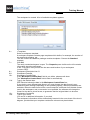
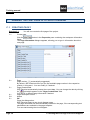
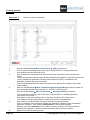
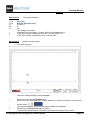
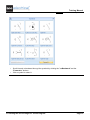
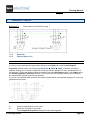
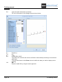
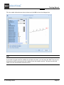
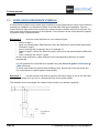
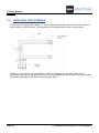
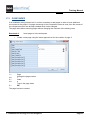
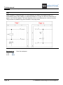
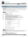
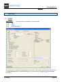
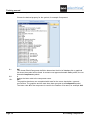
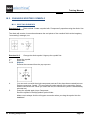
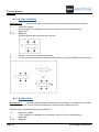
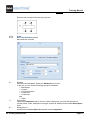
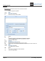
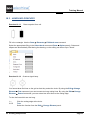
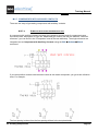
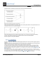
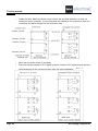
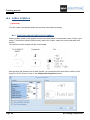
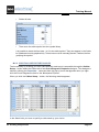
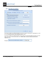
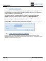
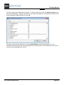
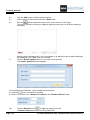
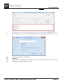
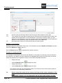
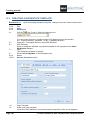
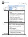
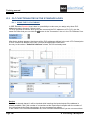
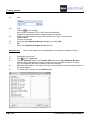
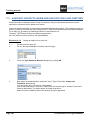
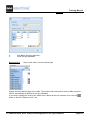
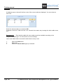
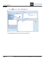
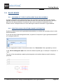
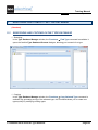
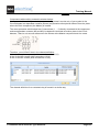
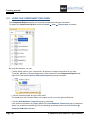
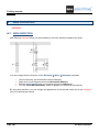
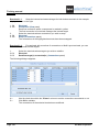
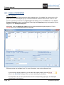
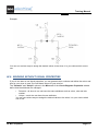
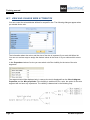
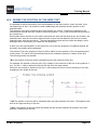
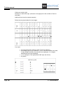
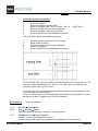
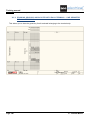
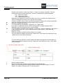
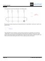
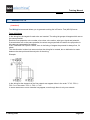
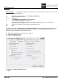
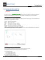
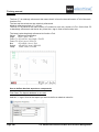
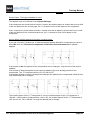
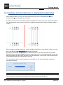
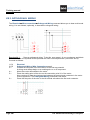
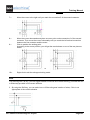
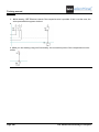
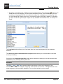
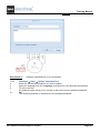
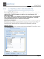
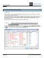
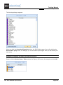
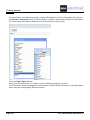
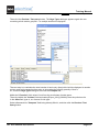
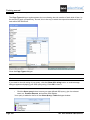
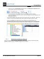
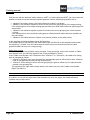
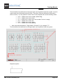
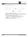
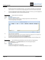
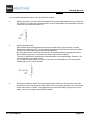
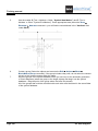
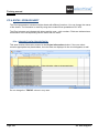
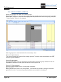
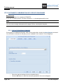
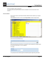
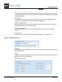
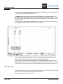
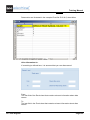
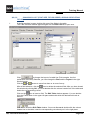
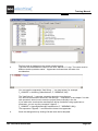
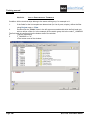
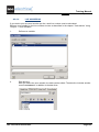
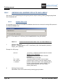
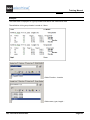
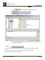
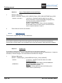
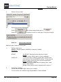
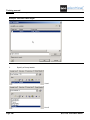
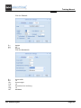
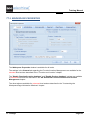
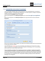
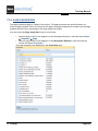
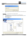
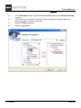
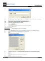
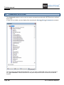
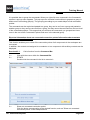
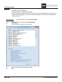
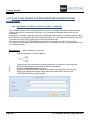
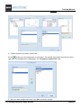
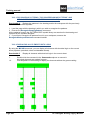
Training manual
COPYRIGHT © 2013 IGE+XAO. All rights reserved
After you click the
button within the "Start Symbol" field, the Symbol browser opens, allowing
you to select the additional symbol used at the first cable core. Its description will be displayed in this
field.
In the same way, you choose the additional symbol to be used at the middle core and the additional
one for the last core of the cable. Their names (descriptions) are displayed, respectively, in the
"Middle Symbol" and "End Symbol" fields. The definition is saved in CABLESNEW.MDB. The file
must be located in your Templates folder. The definitions are available for all workspaces.
In the "Angle" field you have to specify the fixed rotation of your cable at the insertion. Because the
symbols are used, the angle is fixed. If an angle of 0 degree is used, the cable cores are created
from left to right. If an angle of 180 degree is used, the cores are created from right to left. The same
is applied for 90 and 270 degrees.
Hints
1: For creating cable definitions, the various cable symbols must be present in the symbol database.
Symbols must have all the necessary cable symbol properties assigned.
2: The symbols must be created at such angle as it is defined for use.
3: The defined cables are to be stored in the ...Template\CablesNew.mdb database. The cables from
this database are available for all projects.
When you want to use or add a user-defined cable, a dialogue listing all pre-defined cables appears.
Example:
If no use-defined cable exists yet (possible list empty), no list will appear.
In case you choose a user-defined cable, it will be inserted. Otherwise (if you cancel the dialogue),
SEE Electrical will add a basic cable.
Page 98
M. Creating Components