1
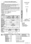
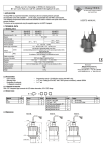
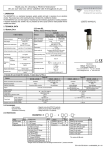
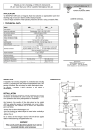
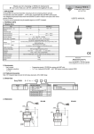
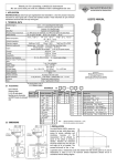
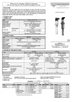
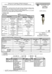
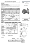
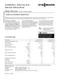
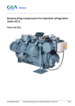
Thank you for choosing NIVELCO instrument. We are sure that you will be satisfied throughout its use! 1. APPLICATION NIVOTRACK magnetostrictive level transmitters are two-wire multifunction, float-type level gauges. They can be used for high accuracy level metering of clean liquids in normal or explosion hazardous environment. Levels of two liquids with different density and their level difference can also be measured with the double float version. Units are available with rigid and with flexible probe. Flexible tube version can mainly be used in large tanks since its transport and installation is much simpler than their counterparts with the same length. Intelligent electronics enable calculation of volume Units require a minimum of maintenance, as the only moving part is the float. The output signal is 4 … 20 mA. HART compatible version is also available. USER’S MANUAL 2. TECHNICAL DATA Types MA ... MC, MD … MG MK ... , MN … Process values measured Level, two levels, level difference Probe version Rigid tube Flexible tube Probe length 0.5 m … 4,5 m 2 m … 10 m Tube material Maximum pressure MEU …, MGU … Plastic coated rigid tube 0.5 m … 3 m Stainless steel: 1.4571 (DIN) 2.5 MPa (25 bar) + PFA coating 1.6 MPa (16 bar) Process temperature (*) 0.3 MPa (3 bar) -40 … +130 °C Non-linearity ± 1 mm Resolution 1 or 5 mm Temperature coefficient 0,04 mm/°C Maximum range: see under Dimensions Minimum range : 200 mm Operating range Zero span Anywhere within the range ∅ 52x52 cylinder or ∅ 95 mm ball(**) St.St. Size/material of the float min. 0.8 g/cm³ Materials of the wetted parts Stainless steel: 1.4571 Manufacturer: NIVELCO Process Control Co. 1043 Budapest, Dugonics u. 11. Telephone: 369-7575 ♦ Fax: 369-8585 e-mail: [email protected] http://www.nivelco.com PFA + PVDF -25ºC … +70ºC Output signal for any process values 4…20 mA (limit values:3.9…20.5 mA) reverse programming also possible Terminal resistance for HART interface ≥ 250 Ohm Damping 10 s, 30 s and 60 s and 0 … 60 s adjustable Fault indication by the output 3.8 mA or 22 mA Output load Rs= (Us-12 V) / 0.02 A Us = power supply voltage 6 digits, 7mm size LCD, engineering units, bargraph Any measured process value can be displayed Display unit (SAP-201) Power supply 12 … 36 V DC II1/2G EEx ia IIB T6 IP 67 (0,5…5 m) Explosion proof protection mark II1/2G EEx ia IIA T6 IP 67 (5…10 m) Imax = 80 mA Pmax = 0.8 W Umax = 30 V Ci < 30 nF Li < 200 µH Ex power supply Electrical protection protection class III Ingress protection IP 67 Process connection According to the order codes Electric connection Cable gland Pg 16 or M 20 x 1,5 Cable: ∅ 8 … 15 mm ; Screw terminals for wires with 1,5 mm2 Housing of electronics Mass 0408 min. 0.5 g/cm³ with float ∅ 95 mm Density Ambient temperature(*) ∅ 76 x 87 mm / cylind. PVDF Paint coated aluminium alloy or plastic (VALOX 412) 1.7 kg + tube: 0.6 kg/m 2.9 kg + tube: 0.3 kg/m 1.7 kg + tube: 0.7 kg/m ** for a pressure of max 1,6 MPA (16 bar) only 2.1 ACCESSORIES *TEMPERATURE DERATING DIAGRAM - User’s Manual - Warranty sheet - Declaration of Conformity - Programming manual (for transmitters with display module only) - 2 pcs cable gland - 1 pc gasket for process connection with BSP thread only (klingerit,oilit) - 1 pc weight - 1 pc M10 nut - 1 pc M10 spring washer - 1 pc M10 washer - 1 pc Spacer (for ∅ 52 float only) for MK and MN types only * In case of process temperature exceeding +70 °C, limits of the ambient temperature are in accordance with the diagram. [ +70 +45 0 +70 +130 [ TÜV-A 03 ATEX 0002X ♦ mba3052a0600h_01 ♦ 4/1 2.2 ORDER CODE (NOT ALL COMBINATIONS ARE POSSIBLE) NIVOTRACK TYPE TUBE / PROCESS CODE • Order length above 5 m - CODE CONNECTION T B E G Transmitter Transmitter + display Transmitter plastic coated tube Tx, plastic coated tube + display M HOUSING A C D G U K N Rigid 1” BSP Rigid 2” BSP Rigid 1” NPT Rigid 2” NPT No process conn. Flexible / 2” BSP Flexible / 2” NPT - CODE CODE 3 4 0 1 2 3 4 5 6 7 8 9 A Aluminium Plastic II1G EEx ia IIA T6 only ACCESSORIES ON REQUEST FLANGE: M F T - LENGTH 0m 1m 2m 3m 4m 5m 6m 7m 8m 9m 10 m CODE 0 1 2 3 4 5 6 7 8 9 0m 0,1 m 0,2 m 0,3 m 0,1 m 0,5 m 0,6 m 0,7 m 0,8 m 0,9 m 1 2 3 4 5 6 7 8 SIZE Code DIN ANSI DN 65 2½” 1 2 DN 80 3” 3 DN 100 4” 4 DN 125 5” 5 DN 150 6” 6 DN 200 8” PRESSURE PN 16 / 150 psi PN 25 / 300 psi Code 1 2 OUTPUT / NUMBER OF FLOAT / EX L (mm) 20 24 S S B (mm) H H (mm) 36 43 38 43 H ∼10 ∼11 B S (mm) 41 70 41 70 L CONNECTION 1” BSP 2” BSP 1” NPT 2” NPT 2 4 6 8 J K A B C E F G L M THREAD (IN THE CODE MIDDLE) Pg16 or M20x1,5 1 2 1” BSP 3 2” BSP 5 1” NPT 6 2” NPT SLIDING SLEEVES FOR THE UNITS WITHOUT PROCESS CONNECTION TYPE MBH-105-2M-300-00 MBK-105-2M-300-00 MBL-105-2M-300-00 MBN-105-2M-300-00 CODE 4 … 20 mA / one float / Ordinary 4 ... 20 mA, HART / one float / Ordinary 4 ... 20 mA / one float / EEx ia 4 ... 20 mA, HART / one float / EEx ia 4 ... 20 mA / one float / EEx ia + EEx d 4 ... 20 mA, HART / one float / EEx ia + EEx d 4 … 20 mA / one float / 5 mm res / Ordinary 4 … 20 mA / two floats / Ordinary 4 … 20 mA, HART / two floats / Ordinary 4 … 20 mA / one float / 5 mm res / EEx ia 4 … 20 mA / two floats / EEx ia 4 … 20 mA, HART / two floats / EEx ia 4 … 20 mA / two floats / EEx ia + EEx d 4 … 20 mA, HART / two floats / EEx ia + EEx d - STANDARD / MATERIAL CODE DIN / steel DIN / 1.4571 DIN / PP DIN / steel + PTFE ANSI / steel ANSI / 1.4571 ANSI / PP ANSI / A38 + PTFE ORDERING BSP NPT 2.3 DIMENSIONS RIGID TUBE TRANSMITTER AND THREADED PROCESS FLEXIBLE TUBE TRANSMITTER WITH SLIDING SLEEVE TYPE: MK… MN… CONNECTION TYPE: MA … MC, MD … MG PLASTIC COATED RIGID TUBE TRANSMITTER TYPE: MEU… MGU… ~90 ~90 ~330 2x 1/2" NPT S 2 x Pg 16 2 x 1/2" NPT ~350 ±130 2 x Pg 16 2 x 1/2" NPT ~300 (170-430) 2 x Pg 16 ~90 A 190 (160 - 320) S A 28 ** * UP UP * * M L M 20 mA L 20 mA C UP M C 20 mA L 4 mA 4 mA B 110 B 100 B 195 4 mA Mmax = L - B - A – C/2 L = Order length M = Measurement range Mmax = L - B - A –C/2 B = No measurement zone 2/4♦ TÜV-A 03 ATEX 0002X ♦ mba3052a0600h_01 A = No measurement zone A = 190 mm C = Height of the float Mmax = L - B – C/2 * Float size see in the Technical Data ** Flange on request 3. INSTALLATION 4. WIRING • The unit should be located in an area, which allows easy access for service, calibration and monitoring. This transmitter is designed to operate on 12 … 36 V DC power only. The maximum loop resistance (including barrier resistance) is depending on the voltage of the power supply and can be between 0 and 1200 Ohm. Calculation formula can be seen in the Technical Table under Output Load. Using transmitter with HART a terminal resistance with a minimum value of 250 Ohm should be applied. The power supply should be interconnected with the unit with twisted, shielded cable that can be pulled through the cable conduit. The cable can be connected to the terminal strip after removing the cover and the display unit. CAUTION: the enclosure of the transmitter should be grounded. Grounding resistance < 1 ohm. If the enclosure can not be grounded the negative line of the loop has to be grounded. • Waving, turbulence and heavy vibration affects accuracy of the measurement. Thus the unit has to be installed far away from devices or places causing such disturbance for instance from openings for filling or emptying. These affects can be attenuated in applications with rigid tube probes by the use of stilling pipe along the whole probe. • To ensure consistent and durable operation the process fluid should be free of suspended solids or materials, which could stick between the float and the guide tube. • The unit should be protected against direct heat radiation. • Design dimensions of the unit and the tank as well as calculations should be checked before mounting. • Before installation a preliminary operational check is suggested. ! The unit may be damaged by electrostatic discharge (EDS), via its terminal thus used commonly precautions should be applied to avoid electrostatic discharge e.g. touching a properly grounded point before removing the cover of the enclosure. • The unit is offered with a wide variety of process connections according to the order codes Tank opening exceeding the float diameter is recommended for insertion. Should this not be possible the float has to be removed from the (rigid or flexible) guide inserted through the opening and the float must be reattached from inside of the vessel. The word “UP” etched on the float is to ensure mounting the float in correct position. • Insertion position of the MEU and MGU types can be adjusted. Free length over the tank however must not be longer than 200 mm. 4...20mA Wiring 5. SET UP, ADJUSTMENT AND PROGRAMMING 5.1 SET UP UP 150 B 195 95 Weight After power up the unit is fully operational, which will be indicated by lighting of the “VALID” LED. HART If the is going on the „COM LED is also on. Value of the current output signal can be measured on the current test point with voltmeter. If the analogue output is 4 mA or 20 mA voltage meter has to show 4 mV or 20 mV respectively. (Can not be used for calibration purposes.) Fault will be indicated by blinking of the „VALID” LED and by change of the output signal in the following events: • Electronic fault; • Range setting too narrow (< 200 mm) • Broken magnet in the float. 120 COM VALID Display module Flexible tube Programming Keys 4mA 20mA Programming Keys 4...20mA UP Current test point - + 52 4 ... 20 mA I- I+ B 195 Displacer 150 • When the weight reaches the bottom the unit should gently be lifted thus spanning the flexible tube. Once feeling resistance of the weight (about 120 … 150 N depending on the length of the cable) but not lifting the weight from the bottom the unit should be fastened by the sliding sleeve. Proper spanning can be checked by the analogue signal or on the display. If the float is at the lowest point Iout < 4 mA or display should read < 0 mm 12 … 36 V DC Shielding at any but one point only Flexible tube • Units with flexible tube of type MK … MN are provided with weight for straightening of the tube and keeping it in position. • When lowering down the flexible tube (with the weight at his end) to the bottom of the tank, special care has to be taken to avoid interlocking or twisting and the coil diameter must not be smaller than 60 cm. Dropping or twitching may damage the unit. Float or floats should be placed next to the weight to avoid its hitting against the weight. Power Supply + Weight Grounding Transmitter with removed cover 120 5.2 ADJUSTMENT Attention! In order to avoid damaging the probe do not put it to torsion when installing or removing the unit. Therefore, special care has to be taken when the process connection is being screwed into or out of the flange. The best is to hold the rigid part of the probe with a suitable tool as long as the process connection is tightened to its place Sliding sleeve must not be loosened during operation. Transmitter can be adjusted to the actual process technology by programming the parameters. Factory Setting is as below: • Measurement mode: level • Current output (4 … 20 mA) assigned to the end values of the maximum range • Fault indication on the current output: :IOut = 22 mA • Damping: 10 s • Engineering units: mm, %, TÜV-A 03 ATEX 0002X ♦ mba3052a0600h_01 ♦ 4/3 5.3 PROGRAMMING Programming without SAP-201 displaqy module: assignment of the 4 and 20 mA to the levels, the fault indication and damping can be modified. This method is recommended for simple applications. Procedure of the programming: pressing keys in relevant sequence and watching state of the LED „VALID” and „COM”. Interpretation of the LED state: = LED off = LED on Assignment of level to 4 mA Action continuously 1) Press key 2) Press additionally key 3) Release keys LED state following the action continuously Programming completed “Fault indication” on the current output Press or for error indication by 3,8 mA or by 22 mA respectively Damping – Use keys / for setting 10 s, 30 s or 60 s and save with pressing E . Er :xxxx dt: xxxx Full programming: highest level of programming with access to all parameters for setting the following: • Measurement configuration • Assignment of 4 mA and 20 mA to levels • Measurement optimalisation • Entering tank dimensions for volumetric calculation • Linearisation Detailed description see in the separate „Programming of NIVOTRACK M-300” Assignment of level to 20 mA 1) Press key Action continuously 2) Press additionally key 3) Release keys LED state following the action ft 3 ft In m3 cm mm Programming keys continuously Programming completed DIST LEV gal l M US VOL 1 Programming keys % mA °C PROG FAIL 2 D t oF sec hour COM VALID Programming “Fault indication” on the current output As a result of programming the output current will be 3,8 mA; 22 mA, or will hold last value for the time the fault lasts. Action 1) Press key continuously 2) Press additionally one of the keys E for 3,8 mA Transmitter with SAP-201 display module 5.4 CONDITIONS OF EX APPLICATION Probe length in connection with gas grouping: for 22 mA continuously 3) Release keys = Action LED state following the action for Programming completed Reset (returning to Factory Setting) Action 1) Press key LED state following the action continuously Reset 2) Press additionally key E continuously 3) Release keys Programming completed After programming completed, LEDs come to the measurement mode. Programming with SAP-201 display module will be aided by displaying parameters and it can be performed by the following two ways. Quickset: recommended for simple applications for assignment of two levels to 4 and 20 mA output, for selection of fault indication and damping. Programming keys + (press for min. 3 s) E , + Function IIB 0,5 … 5 m TEMPERATURE CLASS TYPE MA…, MD…, MK…, MEU…, MA…, MD…, MEU…, MA…, MD…, MEU…, MC… MG… MN… MGU… MC… MG… MGU… MC… MG… MGU… AMBIENT TEMPERATURE -40 °C … +80 °C T6 -25 °C … +70 °C T4 Ex Display Manufacturer’s Setting. 4:xxxx Level xxxx to be assigned to 4 mA current output. Manual adjustment: select with keys level value to / / be assigned to 4 mA and save by pressing E Automatic adjustment: set up tank level to be assigned to 4 mA current output. Measure level with “GET LEVEL” function ( + ) and press E to save. 20:xxxx Level xxxx to be assigned to 20 mA current output. Manual adjustment: select with keys level value to / / be assigned to 20 mA and save by pressing E Automatic adjustment: set up tank level to be assigned to 20 mA current output. Measure level with “GET LEVEL” function ( + ) and press E to save. -20 °C … +95 °C -40 °C … +130 °C -20 °C … +130 °C + Shielding at any but one point only Save displayed value proceeding to the next screen Reload value previous (CANCEL modification) -40 °C … +95 °C Ex Adjusting value (increase, decrease, shift blinking) + -20 °C … +70°C -20 °C … +80 °C -25 °C … +59 °C according to the derating diagram -25 °C … +45 °C according to the derating diagram T5 Enter/quit QUICKSET programming mode + PROCESS TEMPERATURE • Transmitter should only be powered by power supply in conformity with the technical data under Point 2 and duly certified for EEx ia IIB or EEx ia IIA. • Enclosure of the housing should be grounded. • Units with plastic coated tube (types MEU and MGU) may be electrostatically loaded therefore: − medium to be measured must be electrically conductive, and with specific resistance not exceeding the value of 104 Ωm even on the most unfavourable places and under the most unfavourable conditions. − speed as well as way of filling and emptying should be chosen according to the medium. "GET VALUE" - function for measuring prevailing level E IIA 3 … 10 m TABLE OF TEMPERATURE GROUPS 4...20mA , Gas group Probe length Programming completed Programming damping 1) Press key E continuously 2) Press additionally one of the keys 10 sec, for 30 sec, for 60 sec continuously 3) Release keys SAP-201 LED state following the action Li < 200 µH Ci < 30 nF galvanically isolated intrinsically safe Power Supply Umax = 30 V DC Imax = 80 mA Pmax = 0,8 watt Wiring of the Ex version 6. MAINTENANCE AND REPAIR The unit does not require routine maintenance, however the probe may need occasional cleaning to remove surface deposits. Repairs will be performed at Manufacturer’s premises. Units returned for repair should be cleaned or disinfected by the customer. 7. STORAGE CONDITIONS Ambient temperature: Relative humidity: -25 °C ... +60 °C max. 98% 8. WARRANTY All NIVELCO products are warranted to be free from defects according to the Warranty Sheet, within two (2) years from the date of purchase. Aug 2003 Technical specification may be changed without notice. 4/4♦ TÜV-A 03 ATEX 0002X ♦ mba3052a0600h_01 230 V AC