1
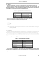
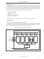
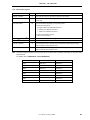
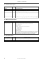
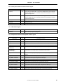
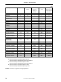
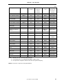
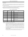
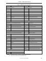
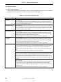
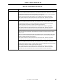
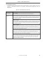
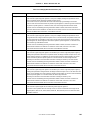
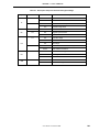
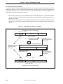
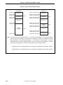
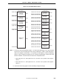
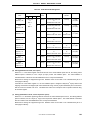
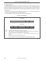
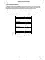
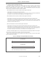
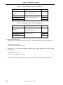
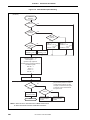
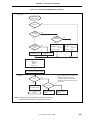
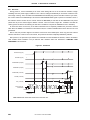
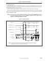
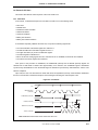
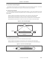
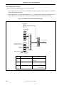
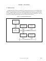
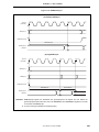
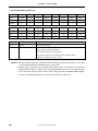
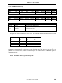
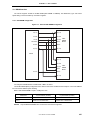
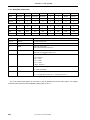
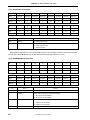
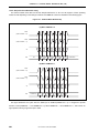
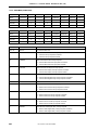
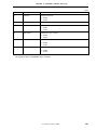
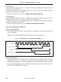
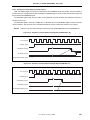
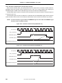
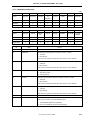
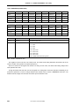
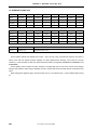
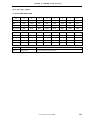
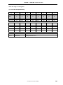
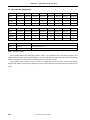
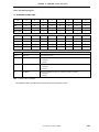
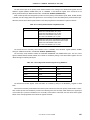
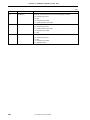
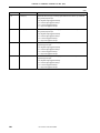
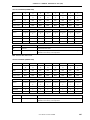
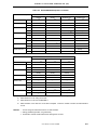
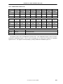
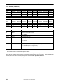
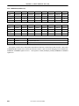
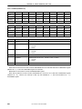
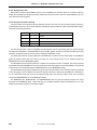
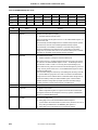
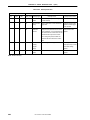
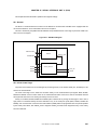
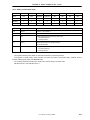
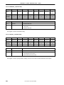
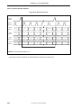
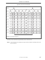
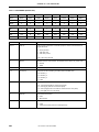
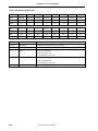
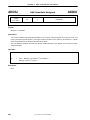
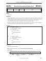
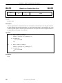
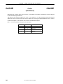
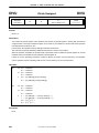
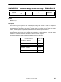
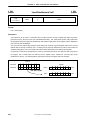
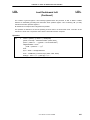
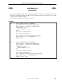
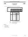
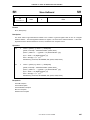
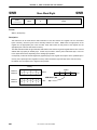
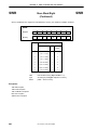
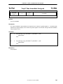
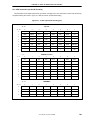
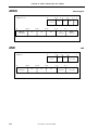
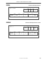
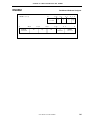
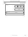
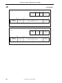
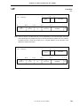
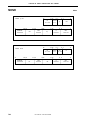
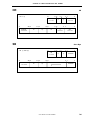
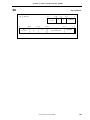
CHAPTER 19 TOUCH PANEL INTERFACE UNIT (PIU)
19.5 Relationships among TPX, TPY, ADIN, and AUDIOIN Pins and States
State
PadState(2:0)
TPX(1:0)
Note
PIU disable (pen status detection)
Disable
Low-power standby
Standby
TPY(1:0)
ADIN(3:0)
HH
D−
−−−−
00
00
−−−−
Pen status detection
WaitPenTouch/Interval
HH
D−
−−−−
Voltage detection at general-purpose AD0 port
ADPortScan
00
00
−−−I
Voltage detection at general-purpose AD1 port
ADPortScan
00
00
−−I−
Voltage detection at general-purpose AD2 port
ADPortScan
00
00
−I−−
Voltage detection at audio input port
ADPortScan
00
00
I−−−
TPY1=H, TPY0=L, TPX0=samp (X+)
PadDataScan
−I
HL
−−−−
TPY1=L, TPY0=H, TPX0=samp (X–)
PadDataScan
−I
LH
−−−−
TPX1=H, TPX0=L, TPY0=samp (Y+)
PadDataScan
HL
−I
−−−−
TPX1=L, TPX0=H, TPY0=samp (Y−)
PadDataScan
LH
−I
−−−−
Touch pressure detection (Z)
PadDataScan
HH
d−
−−−−
Note The states of pins are not guaranteed when the PadState(2:0) that precedes the CPU’s Suspend or
Hibernate instruction execution is in a state other then the Disable state.
Remarks
0
: Low level input
1
: High level input
L
: Low level output
H : High level output
l
: A/D converter input
D : Touch interrupt input (with a pull-down resistor)
d
: No touch interrupt input (with a pull-down resistor)
−
: Don’t care
Z : Hi-Z (high-impedance)
User’s Manual U14272EJ1V0UM00
425