1
MYD-SAM9X5 User Manual
MYD-SAM9G15/9G25
/9G35/9X25/9X35
User Manual
Version V1.6
MYD-SAM9X5 User Manual
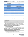
Version History
Version
Description
Time
Number
V1.0
Initial Version
2012.07.23
V1.1
(1) Modify JP6 description in chapter 2.4
(2) Modify program errors in chapter 4.8.2
(3) Modify program in chapter 4.9.1
2012.08.29
V1.2
Modify the description of serial port and SDCard in
Table 2-1
2012.12.05
V1.3
modify
the
phenomenon
explanation
of
usb_audio_looprec, add a rs485 sample program,add
7.0-inch screen support, correct the instructions of JP8
for MDK and Linux downloadadd, add two methods of
u-boot compiling, screen calibration instructions, etc.)
2013.02.22
V1.4
modify the contact infomation)
2013.03.28
V1.5
add Qt support, modify the image path and the
manually download picture of Linux; modify the SAMBA
path in ” 4.3.1 Install download tool” and “5.3.1 Install
Download Tool”
2013.04.24
V1.6
ARM cross-compiler tool upgrade to 2010 version
2013.06.24
MYD-SAM9X5 User Manual
Directory
Chapter 1 Product Overview ............................................................................................ 1
1.1 Product Description ..................................................................................................... 1
1.2 Product Preview ........................................................................................................... 1
1.3 Product Features .......................................................................................................... 2
1.4 Product Configuration .................................................................................................. 5
Chapter 2 Hardware Introduction..................................................................................... 6
2.1 CPU module+Base Board Resources Overview ..................................................... 6
2.2 CPU module Introduction ............................................................................................ 7
2.2.1 CPU......................................................................................................................... 7
2.2.2 DDRAM .................................................................................................................. 7
2.2.3 Clock Circuit........................................................................................................... 8
2.2.4 Serial DATAFLASH .............................................................................................. 9
2.2.5 NANDFLASH ....................................................................................................... 10
2.2.6 Serial EEPROM .................................................................................................. 11
2.2.7 LED ....................................................................................................................... 12
2.2.8 Encoding Switch Setting .................................................................................... 13
2.3 Base Board Introduction............................................................................................ 13
2.3.1 Universal Serial ................................................................................................... 13
2.3.2 CAN BUS ............................................................................................................. 14
2.3.3 JTAG Interface .................................................................................................... 15
2.3.4 LCD Interface ...................................................................................................... 16
2.3.5 User Interface ...................................................................................................... 16
2.3.6 Audio Module WM8731...................................................................................... 17
2.3.7 USB Module ......................................................................................................... 18
2.3.8 Telephone Interface............................................................................................ 21
2.4 Jumper Setting ........................................................................................................... 22
Chapter 3 MDK Routines................................................................................................. 23
3.1 Overview ...................................................................................................................... 23
3.2 Preparation.................................................................................................................. 23
MYD-SAM9X5 User Manual
3.2.1Configure and Compile ....................................................................................... 23
3.2.2 MDK Routine Debug........................................................................................... 30
3.2.3 Super Terminal Configuration ........................................................................... 31
3.2.4 Manual Download ............................................................................................... 35
3.2.5 Automatic Download ........................................................................................... 39
3.3 MDK Routine Introduction......................................................................................... 40
3.3.1 getting-started...................................................................................................... 41
3.3.2 adc_adc10 ........................................................................................................... 41
3.3.3 adc_touchscreen................................................................................................. 43
3.3.4 can......................................................................................................................... 44
3.3.5 dma ....................................................................................................................... 45
3.3.6 lcd .......................................................................................................................... 47
3.3.7 periph_protect...................................................................................................... 48
3.3.8 pmc_clock_switching.......................................................................................... 49
3.3.9 pwm....................................................................................................................... 51
3.3.10 ssc_dma_audio ................................................................................................. 52
3.3.11 twi_eeprom ........................................................................................................ 54
3.3.12 usart_serial ........................................................................................................ 55
3.3.13 emac0 ................................................................................................................. 56
3.3.14 emac1 ................................................................................................................. 57
3.3.15 hsmci_multimedia_card ................................................................................... 58
3.3.16 hsmci_sdcard .................................................................................................... 59
3.3.17 smc_nandflash .................................................................................................. 60
3.3.18 spi_serialflash.................................................................................................... 62
3.3.19 usb_audio_looprec ........................................................................................... 63
3.3.20 usb_cdc_serial .................................................................................................. 64
3.3.21 usb_core ............................................................................................................ 65
3.3.22 usb_hid_keyboard ............................................................................................ 66
3.3.23 usb_hid_mouse................................................................................................. 67
3.3.24 usb_hid_msd ..................................................................................................... 68
MYD-SAM9X5 User Manual
3.3.25 usb_hid_transfer ............................................................................................... 71
3.3.26 usb_iad_cdc_cdc .............................................................................................. 74
3.3.27 usb_iad_cdc_hid ............................................................................................... 75
3.3.28 usb_iad_cdc_msd............................................................................................. 77
3.3.29 usb_massstorage ............................................................................................. 79
Chapter 4 Linux System Guide ...................................................................................... 82
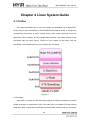
4.1 Outline.......................................................................................................................... 82
4.2 Software Resources .................................................................................................. 83
4.3 Start Linux system ..................................................................................................... 84
4.3.1 Install download tool ........................................................................................... 84
4.3.2 Connect Board and PC ...................................................................................... 84
4.3.3 Automatical Download ....................................................................................... 85
4.3.4 Manual Download ............................................................................................... 85
4.4 Linux Development Environment Structure............................................................ 95
4.5 Installation and Compile ............................................................................................ 95
4.5.1 Create a Working Directory ............................................................................... 95
4.5.2 Install Cross Compiler Tools ............................................................................. 96
4.5.3 Install AT91Bootstrap Source and Compile .................................................... 96
4.5.4 Install uboot Source and Compile .................................................................... 96
4.5.5 Install Linux kernel Source Code and Compile .............................................. 97
4.6 Make the Linux File System ..................................................................................... 98
4.6.1 Write a Demo Program helloworld ................................................................... 98
4.6.2 Mount UBIFS File System ................................................................................. 99
4.6.3 Modify UBIFS System Files ............................................................................ 100
4.6.4 Regenerate UBIFS System File ..................................................................... 100
4.7 Linux Use................................................................................................................... 102
4.7.1 Touch Screen Calibration ................................................................................ 102
4.7.2 U disk Use .......................................................................................................... 103
4.7.3 SD Card Use ...................................................................................................... 104
4.7.4 Play MP3 Music ................................................................................................ 105
MYD-SAM9X5 User Manual
4.7.5 Network Port Test ............................................................................................. 105
4.7.6 Telnet Test ......................................................................................................... 107
4.7.7 RTC Use............................................................................................................. 108
4.8 Linux Driver Development Examples .................................................................... 109
4.8.1 Hardware Schematic ........................................................................................ 109
4.8.2 Driver Source Code .......................................................................................... 109
4.8.3 Compile the Driver ............................................................................................ 113
4.8.4 Load Driver into Board ..................................................................................... 115
4.9 Application Development Instance ........................................................................ 116
4.9.1 Source Code Compilation................................................................................ 116
4.9.2 Compile .............................................................................................................. 117
4.9.3 Application Use ................................................................................................. 117
Chapter 5 Android System Guide ................................................................................ 125
5.1 Overview .................................................................................................................... 125
5.2 Software Resources ................................................................................................ 126
5.3 Build Android System .............................................................................................. 126
5.3.1 Install Download Tool ....................................................................................... 127
5.3.2 Connect Board and SAM-BA .......................................................................... 127
5.3.3 Automatic Download ........................................................................................ 128
5.3.4 Manual Download ............................................................................................. 128
5.4 Compile Android System Files ............................................................................... 138
5.4.1 Android System Principle ................................................................................. 138
5.4.2 Compile System Files ...................................................................................... 139
5.5 Android System Use ................................................................................................ 140
5.5.1 USB Keyboard Test .......................................................................................... 141
5.5.2 Browse Picture Test.......................................................................................... 141
5.5.3 Play Audio Test ................................................................................................. 142
5.5.4 Ethernet Test ..................................................................................................... 143
Appendix 1 FAQ ............................................................................................................. 147
Appendix 2 After-sales service and technical support .....................错误!未定义书签。
MYD-SAM9X5 User Manual
Chapter 1 Product Overview
1.1 Product Description
MYIR has lunched MYD-SAM9X5 series boards which are based on Atmel
AT91SAM9X5 series processor (AT91SAM9G15/25/35, AT91SAM9X25/35, based on the
ARM926EJ-S kernel). Running at up to 400 MHz, MYD-SAM9X5 have 256MB NandFlash,
4MB DataFlash,128MB DDR2 SDRAM and supports Linux 2.6.39 as well as Android 2.3.5
operating system, which also provides relevant sources and have rich peripheral
interfaces: High-speed USB2.0, Audio input, Audio output, LCD interface, CAN interface,
10/100Mbps Ethernet MAC, JTAG debug interface, Serial port and Micro SD card
interface.
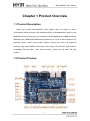
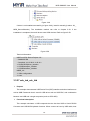
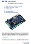
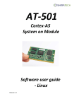
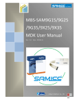
1.2 Product Preview
1
MYD-SAM9X5 User Manual
Figure 1-1
1.3 Product Features
Based on AT91SAM9X5 processor, MYD-SAM9X5 integrates all the chip functions
and features. The main features are as follows:
Extensive Peripherals for Connectivity
Include Ethernet, USB2.0 Device, USART, SD Card and so on.
High-performance Data Speedway
Running at up to 400MHz, Atmel SAM9X5 series microprocessor has a high data
bandwidth architecture based on 12-layer bus matrix.
Next-generation Memory
LPDDR/DDR2 support ensures supply and cost efficiency. In addition, these
MPUS feature MLC/SLC NAND Flash support 24-bit error code correction.
Low Power and Low System Cost
In backup mode, power consumption is only 300uW/MHz at 400MHz operation
and 8uA. 3.3V IOs eliminate the need for external level shifter, while 0.8mm ball
pitch packages reduce PCB design complexity and cost.
The following simple lists the basic features of MYD-SAM9X5.
Electrical parameters
Operating Temperature: -40℃~85℃
Electrical Specifications: +5V power supply
Mechanical Dimensions:
Base Board: 150 mm x 108 mm
CPU module: 86 mm x 68 mm
Processor
AT91SAM9G15/G25/G35/X25/X35 (32 bits ARM RISC processor) runs at up to
400MHz
16KB Data Cache, 16KB Instruction Cache
Memory
2
MYD-SAM9X5 User Manual
32KB Chip SRAM, 64KB Chip ROM
256MB NandFlash, 4MB DataFlash
A 128MB DDR2 SDRAM.
Audio and Video Interface
An Audio 3.5mm Input Interface
A Two-channel Audio 3.5mm Output Interface
LCD Touch-Screen Interface
24 True Color
Resolution: Current 4.3-inch 480x272 and 7.0-inch 800x480, the highest can
reach up to 1280 x 860
Note: Only MYD-SAM9G15、MYD-SAM9G35、MYD-SAM9X35 have graphical output
function.
Transmission Interface
Standard JTAG Interface
Micro SD Card Interface
Serial Ports
A DBGU Port (Debug Unit)
A USART0 (Shared With RS485)
RS485 Interface sharing with USART0 can switch function by Jumper.
Two CAN Interfaces (Only MYD-SAM9X25 and MYD-SAM9X35 have CAN
Interface)
2 High-speed USB HOST Interfaces
A Mini USB OTG Interface
Ethernet MAC
MYD-SAM9G15 doesn’t have Ethernet MAC
MYD-SAM9X25 has two Ethernet MAC (J10 and J11)
Others (MYD-SAM9G25、MYD-SAM9G35、MYD-SAM9X35) have only a
Ethernet MAC.
LED Indicator
A Power Indicator (CPU module: Red)
3
MYD-SAM9X5 User Manual
A Users Light/System Heartbeat Light (CPU module: Blue)
A Power Indicator (Base Board: Red)
4
MYD-SAM9X5 User Manual
1.4 Product Configuration
No
Name
MYD-SAM9X5
Number
Note
Development
1
1
Base Board+CPU module
Board
2
1.5 Meters Crossover Cable
1
3
1.5 Meters Mini USB 2.0 Cable
1
4
5V/2A DC Power adapter
1
5
Serial Cable
1
6
Product DVD
1
Include
Schematic
(PDF),
Manual, Source Code, etc.
7
4.3/7.0 Inch LCD Touch Screen
1
5
optional
User
MYD-SAM9X5 User Manual
Chapter 2 Hardware Resource
Introduction
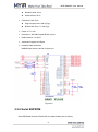
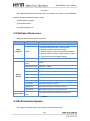
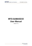
2.1 CPU module+Base Board Resources Overview
SAM9x5 resources are shown in table2-1:
Name
9X25
9X35
9G15
9G25
9G35
Processor
AT91SAM9G15/9G25/9G35/9X25/9X35(ARM926EJ
-S Core, frequency at up to 400MHz)
Memory
128MB SDRAM
Flash
256MB nandflash; 4MB serial dataflash
EEPROM
64KB serial eeprom
USB HOST
2
2
2
2
2
USB OTG
1
1
1
1
1
Audio Input
1
1
1
1
1
Audio Output
1
1
1
1
1
ETH Port
2
1
0
1
1
DBGU Serial
1
1
1
1
1
UART0
1
1
1
1
1
JTAG
JTAG Interface
1
1
1
1
1
LCD
Support 4.3/7.0 Inch
Touch Screen
0
1
1
0
1
RTC
Real Time Clock On
Board and backup
battery
1
1
1
1
1
Extended
Interface
20 Pins User
Extended Interface
3
3
3
3
3
Power
5V Power Input
1
1
1
1
1
SD Card
Micro SD
1
1
1
1
1
CAN
CAN Interface
2
2
0
0
0
RS485
RS485 Interface
1
1
1
1
1
User Button
2
2
2
2
2
System Button
2
2
2
2
2
1
1
1
1
1
USB
Audio
Network
Serial
Button
Telephone Interface
Table 2-1
6
MYD-SAM9X5 User Manual
2.2 CPU module Introduction
2.2.1 CPU
The ARM926EJ-S processor features a Jazelle technology enhanced 32-bit RISC
CPU, flexible size instruction and data caches, tightly coupled memory(TCM) interfaces
and memory management unit(MMU). It also provides separate instruction and data
AMBA AHB interfaces suitable for Multi-layer AHB based systems. The ARM926EJ-S
processor implements the ARMv5TEJ instruction set which includes an enhanced
16x32-bit multiplier capable of single cycle MAC operations and 16-bit fixed point DSP
instructions to enhance performance of many signal processing applications as well as
supporting Thumb technology.
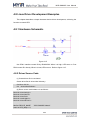
2.2.2 DDRAM
DDRAM chooses H5PS1G63JFR. Its characteristics are as follows:
VDD=+1.8V±0.1V, VDDQ= +1.8V ±0.1V
All inputs and outputs are compatible with SSTL_18 interface
Auto refresh and self-refresh
Organizational structure:8 blanks, Page size:2K,Bit wide:16bit,Total size: 64M x
16
Programmable CAS latency 3, 4, 5and 6 supported
Programmable additive latency 0, 1, 2, 3, 4 and 5 supported
Programmable burst length 4/8 with nibble sequential and interleave mode
Full strength driver option controlled by EMR
Refresh Cycle
0 C°~ 85 C°: 7.8 us
85 C°~ 95 C°: 3.9 us
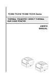
DDRAM circuit peripheral is shown in figure 2-1:
7
MYD-SAM9X5 User Manual
Figure 2-1
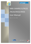
2.2.3 Clock Circuit
(1) Internal clock choose 12 MHz crystal. Clock Circuit is shown in figure 2-2:
8
MYD-SAM9X5 User Manual
Figure 2-2
(2) RTC clock chooses 32.768 KHz crystals. Circuit is shown in figure 2-3:
Figure 2-3
(3) RMII mode chooses 50MHz clock. Circuit is shown in figure 2-4:
Figure 2-4
2.2.4 Serial DATAFLASH
DATAFLASH chooses AT25DF321. Its characteristics are as follows:
Single 2.7V-3.6V Supply
Serial Peripheral interface (SPI) Compatible
Support SPI Modes 0 and 3
70 MHz Maximum Clock Frequency
Flexible, Uniform Erase Architecture
4-Kbyte Blocks,32-Kbyte Blocks,64-Kbyte Blocks, Full Chip Erase
Individual Sector Protection with Global Protect/Unprotect Feature
64-Kbyte Physical Sectors
9
MYD-SAM9X5 User Manual
Hardware Controlled Locking of Protected Sectors
Flexible Programming
Byte/Page Program(1 to 256 Bytes)
Automatic Checking and Reporting of Erase/Program Failures
JEDEC Standard Manufacture and Device ID Read Methodology
Low Power Dissipation
7 mA Active Read Current (Typical)
15 µA Deep Power-Down Current (Typical)
Endurance:100,000 Program/Erase Cycles
Data Retention: 20 Years
Complies with Full industrial Temperature Range
Industry Standard Green (Pb/Halide-free/RoHS Compliant) Package Options
8-lead SOIC (200 mil wide)
16-lead SOIC (300 mil wide)
Processor has two SPI. SPI0 controls data flash. Refer to figure 2-5:
Figure 2-5
2.2.5 NANDFLASH
NANDFLASH chooses K9F2G08U0B. Its characteristics are as follows:
Organization:
Page size: 2K + 64 Bytes
Block size: 128K + 4K Bytes (64 Pages)
Total size: 256M + 8M Bytes(2048 Blocks)
Read Operation:
10
MYD-SAM9X5 User Manual
Random Read: 25 us
Serial Access: 25 ns
Fast Write Cycle Time:
Page Program time: 200 us(Typ)
Block Erase Time: 1.5 ms (Typ)
Power: 2.7V–3.6V
Endurance: 100,000 Program/Erase Cycles
Data Retention: 10 Years
Automatic Program and Erase
Hardware Data Protection
NANDFLASH circuit is shown in figure 2-6:
Figure 2-6
2.2.6 Serial EEPROM
Serial EEPROM chooses AT24C512B. Its characteristics are as follows:
11
MYD-SAM9X5 User Manual
Low voltage and Standard voltage operation
1.8V (Vcc=1.8V to 3.6V)
2.5V (Vcc=2.5V to 5.5V)
Internally organized 65,536 x 8
Two-wire Serial interface
Schmitt Triggers, Filtered input for Noise suppression
Bidirectional Data Transfer Protocol
1 MHz (2.5V, 5.5V), 400KHz(1.8V)Compatibility
Write Protect Pin for Hardware and Software Data Protection
128-byte Page Write Mode (Partial Page Writes Allowed)
Self-timed Write Cycle (5 ms Max)
High Reliability
Endurance: 1,000,000 Write Cycles
Data Retention: 40 years
Lead-free/Halogen-free Devices
8-lead PDIP, 8-lead JEDEC SOIC, 8-lead TSSOP
8-ball dBGA2, 8-lead Ultra-Thin Small Array (SAP) Packages
Serial EEPROM Circuit is shown in figure 2-7:
Figure 2-7
2.2.7 LED
System LED and User LED circuits are as shown in figure 2-8:
12
MYD-SAM9X5 User Manual
Figure 2-8
2.2.8 Encoding Switch Setting
Function Description
Num
ON
OFF
SW1
Enable Nandflash
Disable Nandflash
SW2
Enable Dataflash
Disable Dataflash
Table 2-2
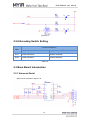
2.3 Base Board Introduction
2.3.1 Universal Serial
Serial circuit is shown in figure 2-9:
13
MYD-SAM9X5 User Manual
Figure 2-9
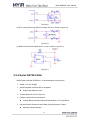
2.3.2 CAN BUS
SAM9X35 and SAM9X25 have two CAN interface which choose TJA1050 chip. Its
characteristics are as follows:
Fully compatible with the “ISO 11898” standard
High speed (up to 1Mbaud)
Very low ElectroMagnetic Emission (EME)
Different receiver with wide common-mode range for high ElectroMagnetic
Immunity (EMI)
An unpowered node does not disturb the bus lines
Transmit Data (TxD) dominant time-out function
Silent mode in which the transmitter is disabled
Bus Pins protected against transients in an automotive environment
Input levels compatible with 3.3V and 5V devices
Thermally protected
Short-circuit proof to battery and to ground
At least 110 nodes can be connected
CAN Bus circuit is shown in figure 2-10:
14
MYD-SAM9X5 User Manual
Figure 2-10
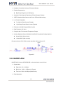
2.3.3 JTAG Interface
JTAG interface which has 20 pins is shown in figure 2-11:
15
MYD-SAM9X5 User Manual
Figure 2-11
2.3.4 LCD Interface
LCD Hardware interface circuit is shown in figure 2-12:
Figure 2-12
2.3.5 User Interface
User interface circuit is shown in figure 2-13:
16
MYD-SAM9X5 User Manual
Figure 2-13
2.3.6 Audio Module WM8731
Audio Performance
97dB SNR (‘A' weighted @ 48kHz) ADC
100dB SNR (‘A' weighted @ 48kHz) DAC
1.42–3.6V Digital Supply Operation
2.7–3.6V Analogue Supply Operation
ADC and DAC Sampling Frequency: 8kHz–96kHz
Selectable ADC High Pass Filter
2 or 3-Wire MPU Serial Control Interface
Programmable Audio Data interface Modes
I2S, Left, Right Justified or DSP
16/20/24/32 bit Word Lengths
Master or Slave Clocking Mode
Stereo sound output and input
The output and input volume control
Highly Efficient Headphone Driver
Playback only 18mW
Analog Pass Through Power only 9mW
Available in 28-lead SSOP or 28-lead QFN package
WM8731 circuit is shown in figure 2-14:
17
MYD-SAM9X5 User Manual
Figure 2-14
2.3.7 USB Module
(1) USB HOST mode chooses AIC1526. Its characteristics are as follows:
110mΩ (5V Input) High-Side MOSFE Switch
500mA Continuous Load Current per Channel
110µA Typical On-State Supply Current
1µA Typical Off-State Supply Current
Current-Limit/Short Circuit Protection
Thermal Shutdown Protection under Overcurrent Condition
Under voltage Lockout Ensures that Switch is off at Start Up
Output can be Forced Higher than Input(Off-State)
Open-Drain Fault Flag
Slow Turn ON and Fast Turn OFF
Enable Active-High or Active-Low
USB HOST Interface circuit is shown in figure 2-15:
18
MYD-SAM9X5 User Manual
Figure 2-15
(2) USB OTG Mode chooses TPS2051BDBV. Its characteristics are as follows:
70-mΩ High-Side MOSFET
500 mA Continuous Current
Thermal and short-Circuit Protection
Accurate Current Limit(0.75A min, 1.25 A max)
Operating Range:2.7V to 5.5V
0.6-ms Typical Rise Time
Deglitched Fault Report
Bidirectional Switch
Ambient Temperature Range: –40°C to 85°C
ESD Protection
USB OTG interface circuit is shown in figure 2-16:
19
MYD-SAM9X5 User Manual
Figure 2-16
20
MYD-SAM9X5 User Manual
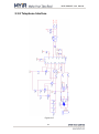
2.3.8 Telephone Interface
Figure 2-17
21
MYD-SAM9X5 User Manual
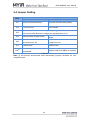
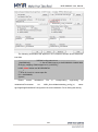
2.4 Jumper Setting
Num
Functional description
Connection
Disconnection
JP1
Boot from External Memory
Boot from Internal ROM (Default)
JP2
Force Power on
Normal Mode
JP3
1-2 Connect: ADC Reference voltage use analog power 3,3V(Defult)
2-3 Connect: ADC Reference voltage use regulated power 3.0V
JP4
Backup Battery Support Power
Disconnect the Backup Battery Power
Supply
JP6
Set USART0 as RS485 function
and output from J19
Set USART0 as RS232 Function and
Output from J16
JP7
Enable CAN1
Disable CAN1
JP8[1]
Enable CAN,
Unavailable
then
DBGU
is
Disable CAN0, then DBGU is available
Table 2-3
Note: [1] JP8 must be disconnected when downloading Program, otherwise PC can’t
recognize board.
22
MYD-SAM9X5 User Manual
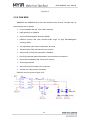
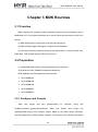
Chapter 3 MDK Routines
3.1 Overview
MDK examples are programs without operating system and its development tool is
MDK-ARM 4.53. This chapter describes how to use and write test procedures, which is as
follows:
(1) MDK development environment to be built and configured;
(2) MDK sample program debugged, compiled and downloaded;
(3) The test procedures introduce methods and phenomenon, including board start,
DMA, ADC, LCD, Storage System, Ethernet and so on.
3.2 Preparation
(1) Install MDK-ARM (Version 4.53) development tool and license
(2) Prepare for MYD_SAM9X5 development board kits
MYD-SAM9X5 series development board includes:
MYD-SAM9G15
MYD-SAM9G25
MYD-SAM9G35
MYD-SAM9X25
MYD-SAM9X35
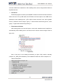
3.2.1 Configure and Compile
Open
test
project
and
take
getting-started
04-MDK_Source\01_getting-started\Project
folder
and
for
example.
double
click
Firstly
find
project
file
(getting-started.uvproj), then configure project. Steps are as follows (Note: Generally,
download program by default setting. Program is necessary to be checked and stetted
23
MYD-SAM9X5 User Manual
when it can't be compiled and downloaded):
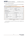
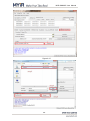
(1) Select project and click right button, then select Option for target ‘MYD-SAM9X35’
or press Alt + F7. The Setting window is shown in figure 3-1:
Figure 3-1
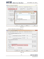
(2) Choose SAM9X35 in Device (Note: The modes are similar to SAM9X35). Steps
are shown in figure 3-2:
24
MYD-SAM9X5 User Manual
Figure 3-2
When default Configuration is completed, Target option will have a default
configuration automatically. Refer to figure 3-1.
(3) Output options (include intermediate file). Refer to figure 3-3:
25
MYD-SAM9X5 User Manual
Figure 3-3
Click “Select Folder For Objects…” Popup a dialog box which can select storage path,
click “OK”, and then user can define executable file name.
(4) The generated intermediate file folder can be selected in the listing tab. Refer to
figure 3-4:
26
MYD-SAM9X5 User Manual
Figure 3-4
(5) User configuration is shown in figure 3-5:
Figure 3-5
27
MYD-SAM9X5 User Manual
The command marked by red box specifies the storage path of generated executable
file and user can modify it.
(6) C/C++ configuration, user can add or delete compile files path. Refer to figure 3-6:
Figure 3-6
(7) Linker Configuration is shown in figure3-7:
Figure 3-7 (1)
28
MYD-SAM9X5 User Manual
Figure 3-7 (2)
The Linker configuration of getting-started project is shown in figure 3-7(1) (generate
ddram.bin, the most MDK routines generate ddram.bin) and the Linker configuration of
pmc_clock_switching project is shown in figure 3-7(2) (generate sram.bin). Both
select .sct file and just have a different name.
(8) Choose project->Rebuild all target files project, or click on shortcut icon to compile.
The steps are shown in figure 3-8:
Figure 3-8
29
MYD-SAM9X5 User Manual
There will be executable bin file in the directory of output option, or can find a prompt
of execute command. Refer to figure 3-9:
Figure 3-9
At this point, the configuration and compilation of MDK routine have been completed.
3.2.2 MDK Routine Debug
The following is MDK program configuration and it needs a hardware emulator
ULink2 in advance. (If need it, please contact company to purchase it)
(1) After opening project file, open the setting dialog box and select Debug. Refer to
figure 3-10:
Figure 3-10
(2) Check hardware emulator ULink2
30
MYD-SAM9X5 User Manual
When connecting ULink2 to board, the indicator lights of RUN and COM change blue
and then turn off, while the indicator lights change red and then remain the same. Thus, it
indicates ULink2 is no problem.
(3) Clicking Setting in figure 3-10, there will be connection status of ULink2 and
development board, as well as kernel identification. Refer to figure 3-11:
Figure 3-11
(4) Click Ctrl+F5 or shortcut icon, or select Debug->Start/Stop Debug Session to start
debug. Refer to figure 3-12:
Figure 3-12
3.2.3 Super Terminal Configuration
Super Terminal Configuration
Opening super terminal configuration, configuration parameter is as follows:
Port: comX (Serial com1, then X is 1); Baud Rate: 115200; Data Bits: 8; Parity Bit:
None; Stop Bit: 1
31
MYD-SAM9X5 User Manual
Note: if there are no special instructions, serial cable is connected to DBUG in MDK
program test.
Download
(1) Install samba software (version 2.11 or above, the installation package in
03-Tools\SAM-BA file folder). If install samba (below version 2.11), uninstall it cleanly.
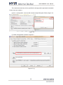
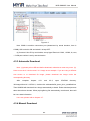
(2) Connect board to PC by mini USB and power on.
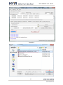
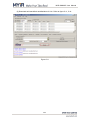
(3) TurnSW1, SW2 off (Note to disconnect the baseboard JP8 jump line, otherwise
the computer will not recognize the development board ), press NRST to reset board, and
you will see tips of installing driver after a certain period of time. The device is shown in
figure 3-13:
Figure 3-13
Note: Turn SW1 on to enable NANDFLASH; turn SW2 on to enable DATAFLASH. Turn
SW1, SW2 off to let chip not boot from two medias,thus enabling to connect to USB.
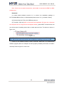
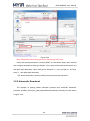
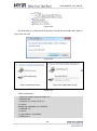
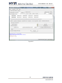
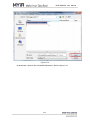
If driver is not installed correctly, install it manually. Right click it to update driver
software program (Note: the sample has been properly installed) and choose to install it
manually. Refer to figure 3-14 and 3-18:
32
MYD-SAM9X5 User Manual
Figure 3-14
Choose to find and install driver software manually.
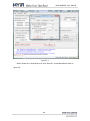
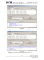
Figure 3-15
Click on red box to enter driver list. Refer to figure 3-16:
33
MYD-SAM9X5 User Manual
Figure 3-16
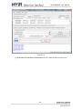
Click “OK” to install driver. Refer to figure 3-17. When installation is finished, it can be
seen in figure 3-18:
Figure 3-17
34
MYD-SAM9X5 User Manual
Figure 3-18
After installing samba driver, download program into board. There are two ways:
download automatically and manually. The below will describe it in detail.
3.2.4 Manual Download
Getting started program introduces download process. Firstly turn on SW1, SW2
(Note to disconnect the baseboard JP8 jump line, otherwise the computer will not
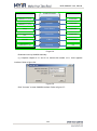
recognize the development board) and press NRST to reset board. Then open samba
software, its startup interface is shown in figure 3-19:
Figure 3-19
35
MYD-SAM9X5 User Manual
Figure 3-20
Refer to figure 3-19, the operation is mainly to choose right board model (Note: this
example use MYD-SAMX35 board, so we select at91sam9x35-ek. If choosing other
MYD-SAM9X5 series, it needs to select the corresponding model. Refer to figure 3-20).
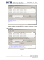
The main interface is shown after clicking “Connect” in figure 3-21:
Figure 3-21
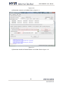
After entering the main interface, turn SW2 on, Refer to figure 3-22. Firstly choose
36
MYD-SAM9X5 User Manual
SerialFlash AT25/AT26, then set the script as Enable SerialFlash, lastly perform
“Execute”:
Figure 3-22
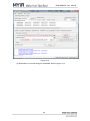
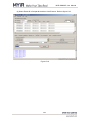
After enabling dataflash, appear “(sam-ba_2.11) 3 % SERIALFLASH::Init 0” and
download
dataflashboot.bin.
(Location:
04-MDK_Source\01_getting-started\Download\9x35). Specific operation is shown in figure
3-23:
37
MYD-SAM9X5 User Manual
Figure 3-23
After downloading dataflashboot file, then download ddram.bin. Specific operation is
shown in figure 3-24:
38
MYD-SAM9X5 User Manual
Figure 3-24
Note: Scripts item without changes are the same as provious step.
Lastly after sending ddram.bin, pressing NRST to reset board (firstly open terminal
and configure parameters referring to chapter 3.2.3), there will be terminal information and
two lights flash alternately. When firstly press character ‘1’, only red light on. And then
press “1”, two lights flash alternately.
The above description is that the whole processes of manual download.
3.2.5 Automatic Download
The example of getting started describes operation and automatic download.
(Location: 04-MDK_Source\01_getting-started\Download\9x35). Directory files are shown
in figure 3-25:
39
MYD-SAM9X5 User Manual
Figure 3-25
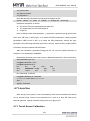
Firstly click right and edit SAM9X35_MDK_dataflash.bat, then COM port modified is
shown in figure 3-26:
Figure 3-26
Native port is COM13, so change COM3 to COM13 (if don’t know which prots to use,
please refer to chapter 3.2.3) and save it. Note: the other doesn’t change.
Then turn SW1, SW2 off (Note to disconnect the baseboard JP8 jump line, otherwise
the computer will not recognize the development board), press NRST to reset board. After
reset it, turn SW2 on and double click SAM9X35_MDK_dataflash.bat, then start to
download program automatically. It will pop up a “logfile” which records steps and
information. (Information is recorded if download fails).
After downloading program and pressing K1 to reset board, program starts to run. At
this point, the process of automatic download has ended. The effective of automatic
download and manual download is the same, so it is recommended to use the automatic
download which can save time.
3.3 MDK Routine Introduction
MDK sample programs are rich which cover board test and use.
Special Note: As to download steps and terminal configuration, please refer to
chapter 3.2. The following programs are no longer describing how to download and
configure terminal. Program test requires relevant preparatory work.
40
MYD-SAM9X5 User Manual
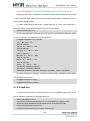
3.3.1 getting-started
Purpose
This example demonstrates chip startup sequence and core peripherals.
Functional description
This program makes two LEDs blink at a fixed rate, then type “1” or “2” to control
LEDs.
Procedures
Download program into board, press NRSRT to observe relevant terminal information.
Typing “1” in terminal make LED1 stop & restart blinking, there will be “1 2” or all “2” in
terminal; Typing “2” in terminal make LED2 stop & restart blinking, there will be “1 2”or all
“1” in terminal.
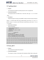
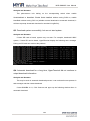
Phenomenon Indicates
Terminal information:
-- Getting Started Example 2.0 --- SAM9XX5-EK
-- Compiled: Jul 9 2012 11:13:49 -Configure PIT
Configure TC.
Configure LED PIOs.
No push buttons, uses DBG key 1 & 2 instead.
Press 1 to Start/Stop the blue LED D1 blinking.
Press 2 to Start/Stop the green LED D2 blinking.
1221221221221221221221221221221221221212212212
221221221222222222222222222212212212211111111111
111111111111111111112122122122122122122122122122
122122122122122122122122122122122122122122122122
122122122122122122122121221221221221221221221221
2212212212212212212212212212212212212212
3.3.2 adc_adc10
Purpose
This example demonstrates ADC peripheral.
Functional description
This example is aimed to demonstrate ADC with/without DMA. When working with
41
MYD-SAM9X5 User Manual
DMA, it works as a big size buffer for ADC peripherals, the data will be stored immediately
without interfering with processor. Steps:
Initialize ADC with expected parameters
Configure and enable interrupt for ADC
Enable DMA reception
Checking the last converted channel in ADC interrupt handler if DMA is not used
Procedures
Download program into board, press NRSRT to observe relevant terminal information.
Typing “d” in terminal enable/disable DMA; character “s” changes mode channel; Figures
0-3, respectively, represent 4 trigger modes; three dates respectively show three AD
sampling data values.
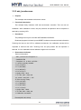
Phenomenon Indicates
Terminal information:
-- ADC12 Example 2.0 --- SAM9XX5-EK
-- Compiled: Jul 9 2012 13:34:14 -=================================
- d: DMA Enable/Disable
- s: Channel sequence switch
- 0, 1, 2,
3: TRIGGER mode:
SW EXT Periodic Continuous
Refresh slow --> fast ....
=================================
= DMA: Enabled; Trigger mode: 0
= Sequence: 09 00 02
=================================
Vols(mV): #09:3300 #00:3300 #02:3232
=================================
- d: DMA Enable/Disable
- s: Channel sequence switch
- 0, 1, 2,
3: TRIGGER mode:
SW EXT Periodic Continuous
Refresh slow --> fast ....
=================================
= DMA: Disabled; Trigger mode: 0
= Sequence: 09 00 02
=================================
Vols(mV): #09:3300 #00:3300 #02:3232
42
MYD-SAM9X5 User Manual
3.3.3 adc_touchscreen
Purpose
This example demonstrates touchscreen events..
Functional description
This example firstly initializes LCD and touchscreen controller. Then let user do
calibration. After calibration is done, the pen positions and pressure will be outputted in
terminal by touching LCD.
Procedures
The package can only be used with MYD-SAM9G15/G35/X35.
Download program into board, press NRSRT to observe relevant terminal information.
Touching the dots on the LCD to calibrate touchscreen, the calibration results will be
outputted in terminal and LCD. Touching LCD, the pen position will be outputted in
terminal. If it isn’t calibrated ok and calibrate it again until it succeed.
Phenomenon Indicates
Terminal information:
-- ADC_Touchscreen Example 2.0 --- SAM9XX5-EK
-- Compiled: Jul 9 2012 14:52:50 --I- I cache is already enabled.
-I- P0: (154,872)
-I- P1: (916,388)
-I- P2: (958,227)
-I- P3: (167,217)
-I- Slope: 2070, -1916
-I- TP: 542, 469 -> 239, 242
-W- X 239, Y 242; Diff -1, 106
-E- Error too big ! Retry...
-I- P0: (156,782)
-I- P1: (940,876)
-I- P2: (957,366)
-I- P3: (172,219)
-I- Slope: 2091, -2520
-I- TP: 548, 438 -> 239, 166
-I- Calibration successful !
Pressed(236,192,10219)
43
MYD-SAM9X5 User Manual
Move (236,192,10219)
Release(236,192)
Pressed(177,145, 4147)
Move (213,179, 3087)
Release(213,179)
3.3.4 can
Purpose
The CAN example demonstrates CAN peripheral.
Functional description
This example is aimed to demonstrate CAN. Test the following CAN operations:
Simple CAN test. CAN1 Mailbox 5 sends data to CAN0 Mailbox 1.
Messages to 1 Mailbox test. CAN1 Mailbox 5 and 6 send data, (6 goes first),
CAN0 Mailbox 2 receives them, but last one is discarded.
Messages to 1 Mailbox test.CAN1 Mailbox 6 and 5 sends data in sequence, with
ID 0x40 and 0x41 that both can accepted by CAN0 Mailbox 3. The last data
overwrites previous one.
Remote data request test. CAN1 Mailbox 5 sends remote request to CAN0
Mailbox 4 to get response data.
Procedures
This example can be used in MYD-SAM9X25/ MYD-SAM9X35 board.
Disconnect JP8 and connectPin7 (CAN1H) to Pin9 (CAN0L), Pin8 (CAN1L) to Pin10
(CAN0L), serial cable to UART0, press NRSRT to observe relevant terminal information.
Phenomenon Indicates
-- CAN Example 2.0 --- SAM9XX5-EK
-- Compiled: Jul 16 2012 10:59:15 -- Test start, DBGU not available now
-I- 0: 210000
- CAN0 Sync OK
-I- 1: 210000
- CAN1 Sync OK
-I- 0:20a00002
44
MYD-SAM9X5 User Manual
-I- 1: a00060
-I- 0:20a00006
-I- 1: a00060
-I- 1:40a00040
- CAN0.1: Simple test data received
- CAN0.2: Messages to 1 Mailbox received
-I- 0: a0000e
- CAN0.3: Messages to 1 Mailbox(OVR) received
-I- 1:20a00060
-I- 0: a0001e
- CAN1.5: Remote requested data received
-I- 1:20a00062
-I- 0: a0007e
-I- 1:20a00066
-I- 0: a0007e
-I- 0:40a0005e
- CAN1.1: Simple test data received
- CAN1.2: Messages to 1 Mailbox received
-I- 1: a0006e
- CAN1.3: Messages to 1 Mailbox(OVR) received
-I- 0:20a0007e
-I- 1: a0007e
- CAN0.5: Remote requested data received
-I- 0: 10007e
-I- 1: 10007e
- Press any key to test again
3.3.5 dma
Purpose
This example demonstrates Atmel’s AT91SAM9X5 microcontrollers.
Functional description
This example demonstrates DMA data transfer. Switch multiple DMA buffers transfer
by the corresponding buttons.
Procedures
Download program into board, press NRSRT to observe relevant terminal information.
0-9, A, B are transmission choices of DMA buffer. “S” starts transporting and displays
45
MYD-SAM9X5 User Manual
menu.
Phenomenon Indicates
Terminal information:
-- DMA Example 2.0 --- SAM9XX5-EK
-- Compiled: Jul 9 2012 16:01:08 -Menu :
------ 1-9, A, B: Programming DMAC for Multiple Buffer Transfers
1: Single Buffer or Last buffer of a multiple buffer transfer
2: Multi Buffer transfer with contiguous DADDR
3: Multi Buffer transfer with contiguous SADDR
4: Multi Buffer transfer with LLI support
5: Multi Buffer transfer with DADDR reloaded
6: Multi Buffer transfer with SADDR reloaded
7: Multi Buffer transfer with BTSIZE reloaded and contiguous DADDR
8: Multi Buffer transfer with BTSIZE reloaded and contiguous SADDR
9: Automatic mode channel is stalling BTsize is reloaded
A: Automatic mode BTSIZE, SADDR and DADDR reloaded
B: Automatic mode BTSIZE, SADDR reloaded and DADDR contiguous
- s: Start DMA transfer
- h: Display this menu
Programming DMAC for Multiple Buffer Transfers in row 1
Programming DMAC for Multiple Buffer Transfers in row 2
Programming DMAC for Multiple Buffer Transfers in row 10
-I- Start DMA transfer
-I- The Source Buffer content before transfer
00 01 02 03 04 05 06 07 08 09 0a 0b 0c
00 02 04 06 08 0a 0c 0e 10 12 14 16 18
00 03 06 09 0c 0f 12 15 18 1b 1e 21 24
00 04 08 0c 10 14 18 1c 20 24 28 2c 30
-I- The Destination Buffer content before transfer
5a 5a 5a 5a 5a 5a 5a 5a 5a 5a 5a
5a 5a 5a 5a 5a 5a 5a 5a 5a 5a 5a
5a 5a 5a 5a 5a 5a 5a 5a 5a 5a 5a
5a 5a 5a 5a 5a 5a 5a 5a 5a 5a 5a
5a
5a
5a
5a
5a
5a
5a
5a
0d
1a
27
34
0e
1c
2a
38
0f
1e
2d
3c
5a
5a
5a
5a
5a
5a
5a
5a
5a
5a
5a
5a
-I- The Source Buffer content after transfer
00 01 02 03 04 05 06 07 08 09 0a 0b 0c 0d 0e 0f
00 02 04 06 08 0a 0c 0e 10 12 14 16 18 1a 1c 1e
00 03 06 09 0c 0f 12 15 18 1b 1e 21 24 27 2a 2d
46
MYD-SAM9X5 User Manual
00 04 08 0c 10 14 18 1c 20 24 28 2c 30 34 38 3c
-I- The Destination Buffer content after transfer
00 01 02 03 5a 5a 5a 5a 5a 5a
5a 5a 5a 5a 5a 5a 5a 5a 5a 5a
5a 5a 5a 5a 5a 5a 5a 5a 5a 5a
5a 5a 5a 5a 5a 5a 5a 5a 5a 5a
Done
5a
5a
5a
5a
5a
5a
5a
5a
5a
5a
5a
5a
5a
5a
5a
5a
5a
5a
5a
5a
5a
5a
5a
5a
3.3.6 lcd
Purpose
This example demonstrates LCD Controller (LCDC) Note: here use 4.3-inch screen
as an example)).
Functional description
This example configures LCDC for LCD to display and then draw test patterns on
LCD.
Procedures
This package can be used in MYD-SAM9G15/G35/X35.
Download program into board, press NRSRT to observe relevant terminal information.
Then test pattern image is displayed on the LCD.
Phenomenon Indicates
Terminal information:
-- LCD Example 2.0 --- SAM9XX5-EK
-- Compiled: Jul 9 2012 16:17:36 --I- I cache is already enabled.
- Test Pattern: 480 x 272 [80 x 68]
- Test Cursor: 32 x 32
- LCD ON
Show: 82,37 32x48 0
Show: 164,76 64x192 0
Show: 246,45 64x-192 0
Show: 328,6 -64x-192 0
Show: 410,31 -64x192 0
Show: 339,70 32x48 0
Show: 257,51 64x192 0
Show: 175,12 192x64 90
47
MYD-SAM9X5 User Manual
Show: 93,135 -192x64 90
Show: 11,80 64x192 180
Show: 70,42 192x64 270
Show: 152,165 192x-64 270
Show: 234,80 64x192 0
3.3.7 periph_protect
Purpose
This program demonstrates PIO controller behavior.
Functional description
This application shows protective mechanism of PIO controller. When the
write-protection is enabled, any write attempt to write-protected registers is abortted. So
register won’t be modified. Besides, the write protect register save register offset address.
Procedures
Download program into board, press NRSRT to observe relevant terminal information.
Typing “l” in terminal will into write-protect mode, while typing “U” will into unprotected
mode.
Phenomenon Indicates
Terminal information:
-- Peripheral Protect Example 2.0 --- SAM9XX5-EK
-- Compiled: Jul 9 2012 16:42:32 --
Enter 'l' to enable Write Protect and enter 'u' to disable Write Protect.
Select the register to be written by a value(0x12345678).
0 : PIO Enable Register
(0x0000)
1 : PIO Disable Register
(0x0004)
2 : PIO Output Enable Register
(0x0010)
3 : PIO Output Disable Register
(0x0014)
4 : PIO Input Filter Enable Register (0x0020)
5 : PIO Input Filter Disable Register (0x0024)
6 : PIO Multi-driver Enable Register (0x0050)
7 : PIO Multi-driver Disable Register (0x0054)
8 : PIO Pull Up Disable Register
(0x0060)
9 : PIO Pull Up Enable Register
(0x0064)
a : PIO Peripheral ABCD Select Register 1
(0x0070)
48
MYD-SAM9X5 User Manual
b : PIO Peripheral ABCD Select Register 2
(0x0074)
c : PIO Output Write Enable Register (0x00A0)
d : PIO Output Write Disable Register (0x00A4)
e : PIO Pad Pull Down Disable Register
(0x0090)
f : PIO Pad Pull Down Enable Register (0x0094)
The Write Protect is enabled.
Write protect violation is detected!
The offset of the write-protected register is 0x0070.
Write protect violation is detected!
The offset of the write-protected register is 0x0094.
The Write Protect is disabled.
No write protect violation is detected.
No write protect violation is detected.
3.3.8 pmc_clock_switching
Purpose
This example demonstrates switch system clock (PLLA, UPLL, SLCK, MAINCK).
Functional description
Upon startup, program configures PIOs for DBUG, PCK. DBUG baud rate is
configured as 1200 bps. This example prints the current configuration and waiting input “’”
to switch system clock.
Procedures
This program is different with others. Firstly DBGU baud is configured as 1200 bps,
while others don’t change. Secondly manual download has a little change, please accord
to the following steps:
Turn SW1, SW2 off, press NRST to reset board and open samba 2.11 software (The
same as manual download in chapter 3.24). Then turn SW2 on, enable SerialFlash and
download sram.bin file. Specific operation is shown in figure 3-27, 3-28:
49
MYD-SAM9X5 User Manual
Figure 3-27
50
MYD-SAM9X5 User Manual
Figure 3-28
Download program into board, press NRSRT to observe relevant terminal information,
and switch system clock by prompt.
Phenomenon Indicates
Terminal information:
** Switch to 1200 bps for DBG **
-- PMC Clock Switching example 2.0 --- SAM9XX5-EK
-- Compiled: Jul 6 2012 14:32:53 ---- Current PMC clock from lowlevel pmc configuration --he slow clock source is internal 32 kHz RC oscillator
PLLA clock is 800 MHz
PLLA clock is the source of Master clock
MCK Master Clock is prescaler output clock divided by 3
-I- Select main clock as the master clock
-I- Please measure the clock on PCK to make sure it is 12000000 Hz...
-I- Press ` to switch next clock configuration...
-I- Select PLLA clock as the master clock
-I- Please measure the clock on PCK to make sure it is 12500000 Hz...
-I- Press ` to switch next clock configuration...
-I- Select UTMI PLL clock as the master clock
-I- Please measure the clock on PCK to make sure it is 7500000 Hz...
-I- Press ` to switch next clock configuration...
-I- Switch the XTAL 32K crystal oscillator to be the source of the slow clock
-I- Please measure the clock on PCK to make sure it is 32768 Hz...
-I- Debuging in EWARM IAR C_SPY, the JLINK will disconnect on some PC!
-I- Press ` to switch next clock configuration...
3.3.9 pwm
Purpose
This example demonstrates PWM channel configuration.
Functional description
Two PWM channels (channel #0, #1) are configured to generate two PWM signals.
Procedures
51
MYD-SAM9X5 User Manual
Download program into board, press NRSRT to observe relevant terminal
information.
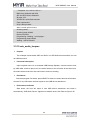
(1) Connecting pin 7 in J2 to pin 8 in J2, blue LED start glowing repeatedly at f1
(2) Connecting pin 7 in J2 to pin 10 in J2, blue LED start glowing repeatedly at f2.
Phenomenon Indicates
Two connection ways led LEDs flashing at different frequencies.
3.3.10 ssc_dma_audio
Purpose
This example demonstrates output an audio stream by WM8731CODEC.
Functional description
This example plays a pre-loaded WAN file into flash. The audio stream is outputted
by WM873 SSC interface. Audio format:
Format: WAV
Sample rate: 48 kHz
Procedures
Download program into board, press NRSRT to observe relevant terminal
information:
-- ssc_dma_audio -Menu :
-----x: Receive WAV f 閘 e with XModem Protocol
X: Receive WAV file through DBGU
Input “x” in terminal
Transfer wav file with 1K XModem, Ctr+ D to cancel
Operation can be done in figure 3-29 and 3-30.
52
MYD-SAM9X5 User Manual
Figure 3-29
Figure 3-30
Starting xmodem transmission after clicking “OPEN”, press Ctrl+C to cancel transfer
and wait end prompt:
53
MYD-SAM9X5 User Manual
100%
274 KB
5 KB/s 00:00:49
0 Errors
-- ssc_dma_audio -Menu :
-----W: Play the WAV file loaded
I: Display the information of the WAV file
x: Receive WAV file with XModem Protocol
X: Receive WAV file through DBGU
Input ‘W’ to choose WAV file and “I” to output audio:
-- ssc_dma_audio -Menu :
-----W: Play the WAV file loaded
I: Display the information of the WAV file
Pressing “W” mounts WAV audio and the terminal display:
-- ssc_dma_audio -Menu:
-----I: Display the information of the WAV file
S: Stop playback
Pressing “I “outputs Audio:
-- WAV file @ 22000000
Wave file header information -------------------------------- Chunk ID
= 0x46464952
- Chunk Size
= 281028
- Format
= 0x45564157
- SubChunk ID
= 0x20746D66
- SubchunNRST Size = 16
- Audio Format
= 0x0001
- Num. Channels = 2
- Sample Rate
= 48000
- Byte Rate
= 192000
- Block Align
=4
- Bits Per Sampl= 16
- Subchunk2 ID
= 0x61746164
- Subchunk2 Size = 280992
-- Press any key to return to menu
Phenomenon Indicates
Terminal outputs information in detail and headphone outputs audio:
3.3.11 twi_eeprom
54
MYD-SAM9X5 User Manual
Purpose
This example program demonstrates TWI peripheral accesses an external serial
EEPROM chip.
Functional description
This example is used to test EEPROM model.
Procedures
Download program into board, press NRSRT to observe relevant terminal
information:
Phenomenon Indicates:
Terminal information:
-- TWI EEPROM Example 2.0 --- SAM9XX5-EK
-- Compiled: Jul 10 2012 16:46:29 --I- Filling page #0 with zeroes ...
-I- Filling page #1 with zeroes ...
-I- Read/write on page #0 (polling mode)
-I- 0 comparison error(s) found
-I- Read/write on page #1 (IRQ mode)
-I- Callback fired !
-I- Callback fired !
-I- 0 comparison error(s) found
3.3.12 usart_serial
Purpose
This example demonstrates USART simulate DBUG.
Functional description
On startup, the debug information is printed by DBGU port. USART0 will send back
any character it receives from the HyperTerminal, as well as text file.
Procedures
Download program into board, press NRSRT to observe relevant terminal
information:
-- USART Serial Example 2.0 --- SAM9XX5-EK
55
MYD-SAM9X5 User Manual
-- Compiled: Jul 10 2012 17:08:53 --- Start to echo serial inputs -Unplug the serial cable from DBUG (J18) and insert UART0 (J16). The terminal
displays:
Start waiting data by using DMA:
(1) At this point, pressing the keyboard will echo the corresponding character:
Start waiting data by using DMA:
aa21dsdgfjhtcgfhdtrasrasssssssssssss
(2) Send a txt document. Build a text document and send it. Refer to figure 3-31and
3-32:
Figure 3-31
Figure 3-32
Terminal information:
-- USART Serial Example 2.0 --- SAM9XX5-EK
-- Compiled: Jul 10 2012 17:08:53 --- Start to echo serial inputs -Start waiting data by using DMA:
TEST MYD-SAM9X5!
Phenomenon Indicates:
The phenomenon is explained above.
3.3.13 emac0
Purpose
This example demonstrates Ethernet MAC (EMAC) and Ethernet transceiver.
Functional description
56
MYD-SAM9X5 User Manual
Upon startup, configure board by default IP (192.168.2.115) and MAC address, test
IP by ping command.
Procedures
This example can be used in MYD-SAM9G25/G35/X25/X35 and requires Network
port J11.
(1) Connect board to network or to PC by crosswire. Then set host IP 192.168.2.XX
(Note: XX can’t be 115).
(2) Download program into board, press NRSRT to observe relevant terminal
information:
(3) Open a terminal application and type the following command line: ping
192.168.2.115.
Phenomenon Indicates
Terminal information:
-- EMAC Example 2.0 --- SAM9XX5-EK
-- Compiled: Jul 11 2012 08:35:19 --- MAC 0:45:56:78:9a:bc
-- IP 192.168.2.115
-I- ** Valid PHY Found: 0
-I- AutoNegotiate complete
P: Link detected
Input the command in terminal: ping 192.168.2.115. Refer to figure 3-13:
Figure 3-33
3.3.14 emac1
Purpose
This example demonstrates Ethernet MAC (EMAC) and Ethernet transceiver.
57
MYD-SAM9X5 User Manual
Functional description
Upon startup, configure board by a default IP (192.168.2.115) and MAC address, test
IP by ping command.
Procedures
The program can be used in MYD-SAM9X25 and requires Network port J11.
(1) Connect board to network or to PC by crosswire. Then set host IP 192.168.2.XX
(Note: XX can’t be 115).
(2) Download program into board, press NRSRT to observe relevant terminal
information.
(3) Open terminal and type the following command line: ping 192.168.2.115.
Phenomenon Indicates
Terminal information:
-- EMAC Example 2.0 --- SAM9XX5-EK
-- Compiled: Jul 25 2012 11:36:30 --- MAC 0:45:56:78:9a:bc
-- IP 192.168.2.115
-I- ** Valid PHY Found: 0
-I- AutoNegotiate complete
P: Link detected
Input the command in terminal: ping 192.168.2.115. Refer to figure 3-14:
Figure 3-34
3.3.15 hsmci_multimedia_card
Purpose
This example demonstrates HSMCI interface on SAM microcontrollers.
Functional description
Open HyperTerminal before running this program, run this program, HyperTerminal
58
MYD-SAM9X5 User Manual
will print the test information which includes initialization and performance.
Procedures
Download program into board, press NRSRT to observe relevant terminal information,
and then insert a SD card.
Phenomenon Indicates
Terminal information:
Without insertting a SD card:
-- Basic MultiMedia Card Project 2.0 --- SAM9XX5-EK
-- Compiled: Jul 11 2012 09:09:37 --I- Cannot check if SD card is write-protected
Insert a SD card:
==========================================
-I- SdMmcIdentify.Cmd5: 3
-I- SD MEM
-I- Card Type 2, CSD_STRUCTURE 0
-W- SD 4-bit mode
-I- HS Not Supported in SD Rev 0x0
-I- Set SD/MMC clock to 22222K
-I- SD/MMC card initialization successful
…
Press Enter:
-!- MCK is 133MHz
-!- Buffer@2000b754,size 0x400000
# i,I : Re-initialize card
#t
: Disk R/W/Verify test
#T
: Disk performance test
#p
: Change number of blocks in one access for test
#m
: Change MCI interface used
Input the corresponding command for different operations. Input ‘t”:
==========================================
-!- Test code: 1.clr, 2.wr, 3.rd
-I- Testing block [783232 - 791423]…
3.3.16 hsmci_sdcard
Purpose
This example demonstrates HSMCI interface.
Functional description
59
MYD-SAM9X5 User Manual
This example detects, initializes SD/MMC memory card, and performs R/W test on it.
Procedures
Download program into board, press NRSRT to observe relevant terminal information.
When prompted that “Please insert a card”, start to initialize and test SD card.
Phenomenon Indicates
Terminal information:
-- Basic HSMCI SD/MMC Example 2.0 --- SAM9XX5-EK
-- Compiled: Jul 11 2012 09:48:44 --I- Cannot check if SD card is write-protected
-==========================================
-I- SdMmcIdentify.Cmd5: 3
-I- SD MEM
-I- Card Type 2, CSD_STRUCTURE 0
-W- SD 4-bit mode
-I- HS Not Supported in SD Rev 0x0
-I- Set SD/MMC clock to 22222K
…(Intermediate omit)
==========================================
-!- MCI 0, code: 1.clr, 2.wr, 3.rd
-I- Testing block [783232 - 791423]…
3.3.17 smc_nandflash
Purpose
This example demonstrates s read/write data from/to nandflash SMC.
Functional description
Configure interface between SMC NAND Flash, then test Nandflash.
Procedures
Download program into board, turn SW1 on, press NRSRT to observe relevant
terminal information.
Phenomenon Indicates
Terminal information:
-- SMC NandFlash Example 2.0 --- SAM9XX5-EK
-- Compiled: Jul 11 2012 10:37:14 --
60
MYD-SAM9X5 User Manual
-I- Nandflash ID is 0x9580DA2C
Menu :
------ i: Dump Nand flash information
- d: Enable or disable DMA
- r: Performance test (Raw without ECC)
- s: Performance test (Software ECC)
- p: Performance test (PMECC)
- h: Display this menu
Input “I”:
-I- Size of the whole device in bytes : 0x10000000
-I- Size in bytes of one single block of a device : 0x20000
-I- Number of blocks in the entire device : 0x800
-I- Size of the data area of a page in bytes : 0x800
-I- Number of pages in one block : 0x40
Input “d”:
-I- Initialize DMA done.
-I- Disable DMA done.
-I- Initialize DMA done.
-I- Disable DMA done
Input “r”:
-I- Erase block 10
-I- Write block 10
-I- Raw block write speed 4228K/s
-I- Read block 10
-I- Raw block Read speed 6553K/s
Menu :
------ i: Dump Nand flash information
- d: Enable or disable DMA
- r: Performance test (Raw without ECC)
- s: Performance test (Software ECC)
- p: Performance test (PMECC)
- h: Display this menu
Input “s”:
-I- Disable PMECC using Software ECC.
-I- Erase block 10
-I- Write block 10
-I- Raw block write speed 1506K/s
-I- Read block 10
-I- Raw block Read speed 1899K/s
Menu :
61
MYD-SAM9X5 User Manual
------ i: Dump Nand flash information
- d: Enable or disable DMA
- r: Performance test (Raw without ECC)
- s: Performance test (Software ECC)
- p: Performance test (PMECC)
- h: Display this menu
Input “p”:
-I- Initialize PMECC.
-I- Erase block 10
-I- Write block 10
-I- Raw block write speed 3542K/s
-I- Read block 10
-I- Raw block Read speed 5041K/s
Menu :
------ i: Dump Nand flash information
- d: Enable or disable DMA
- r: Performance test (Raw without ECC)
- s: Performance test (Software ECC)
- p: Performance test (PMECC)
- h: Display this menu
Inputting “h” will display menu.
3.3.18 spi_serialflash
Purpose
This example demonstrates set up SPI and read/write serial data flash.
Functional description
This example tests serial data flash by erasing/writing each pages, and read/write
bandwidth.
Procedures
Download program into board, press NRSRT to observe relevant terminal information.
(Note: Turn SW2 on)
Phenomenon Indicates
Terminal information:
-- SPI with Serialflash Example 2.0 --- SAM9XX5-EK
62
MYD-SAM9X5 User Manual
-- Compiled: Jul 11 2012 11:02:31 -DMA driver initialized with IRQ
SPI and AT25 drivers initialized
ID read: 471f
AT25DF321 serial flash detected
Flash unprotected
Chip is being erased...
After a certain period of time:
Checking erase ...
Checking page #16383
Erase successful.
Programming a walking 1 on all pages ...
Programming page #16383
Walking 1 test successful.
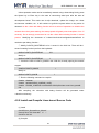
3.3.19 usb_audio_looprec
Purpose
This example demonstrates UDP and DACC on AT91SAM microcontrollers, as well
as USB framework.
Functional description
Input loop back sound to a simulated USB Desktop Speaker, connect board to host
by USB cable, and then play music, the audio stream is sent to board. At the same time,
the audio stream received is also sent back to host for recording.
Procedures
Download program into board, press NRSRT to observe relevant terminal information,
connect PC by USB cable, the host reports a new USB device attachment.
Phenomenon Indicates
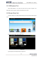
Start board, the host will report a new USB device attachment and install it
automatically. “USB Audio Device” appears in hardware device list. Refer to figure 3-35:
63
MYD-SAM9X5 User Manual
Figure 3-35
Terminal information:
-- USB Device Audio LoopREC Example 2.0 --- SAM9XX5-EK
-- Compiled: Jul 13 2012 10:02:27 -USBD_Init
3.3.20 usb_cdc_serial
Purpose
This example demonstrates USB Device Port (UDP) and USART interface on
AT91SAM microcontrollers, as well as USB Framework.
Functional description
This demo simulates a USB to RS-232 Serial Port Converter
Procedures
Download program into board, press NRSRT to observe relevant terminal information,
host will report a new USB device attachment (Note: it may be not appeared in some
computers). There will be additional serial port after installing driver.
Phenomenon Indicates:
There will be device in the figure 3-26:
64
MYD-SAM9X5 User Manual
Figure 3-36
Updating driver (location: 04_MDK_Source\libraries\usb\device), there will be
additional “AT91 USB to Serial Converter (COM18)” in the device. Refer to figure 3-37:
Figure 3-37
Terminal information:
USB Device CDC Serial Project 2.0 --- SAM9XX5-EK
-- Compiled: Jul 11 2012 11:44:04 --I- CDCDSerial_Initialize
-I- CDCDSerialPort_Initialize
USBD_Init
-- ESC to Enable/Disable ECHO on cdc serial --- TAB to Enable/Disable DEBUG log output --I- VBus configuration
-I- conn
3.3.21 usb_core
Purpose
This example demonstrates UD interface on AT91SAM microcontroller.
Functional description
Connect PC by USB cable, and host will notice USB device attachment.
Procedures
Download program into board, press NRSRT to observe relevant terminal information,
connect to PC by USB cable, the host reports a new USB device attachment. (Note: some
computers maybe not report it). The device manger is shown in figure 3-38:
Phenomenon Indicates
New hardware USB device can be found in device manger. Refer to figure 3-38:
65
MYD-SAM9X5 User Manual
Figure 3-38
Specially Note: the left is the test result of Winows7 system while the right is the test
result of Windows XP system.
Terminal information:
USB Device Core Project 2.0 --- SAM9XX5-EK
-- Compiled: Jul 13 2012 09:06:43 --I- USB initialization
USBD_Init
-I- Connecting device
-I- VBus configuration
-I- conn
Rsm Susp Rsm Std gDesc Dev Std sAddr SetAddr(5) Std gDesc Dev Std gDesc Cfg
Std gDesc Cfg Std gDesc Cfg
3.3.22 usb_hid_keyboard
Purpose
This example demonstrates UDP and PIO interface on AT91SAM microcontrollers,
USB Framework that is used for USB driver such as USB HID.
Functional description
This example simulates a simple keyboard. Connect to host by USB cable, host
reports a new hardware attachment. Refer to figure 3-39:
Figure 3-39
After installing driver, new USB Device appears in the hardware device list. As shown
in figure 3-40:
66
MYD-SAM9X5 User Manual
Figure 3-40
Procedures
Download program into board, press NRSRT to observe relevant terminal information,
PC reports new device and installs it automatically. After installing it, a new USB device is
added to human input device in the device manger.
Phenomenon Indicates
A new USB device is added in device manger. Refer to figure 3-39:
Terminal information:
USB Device HID Keyboard Project 2.0 --- SAM9XX5-EK
-- Compiled: Jul 13 2012 10:33:42 --- : DBG key 1 2 used as buttons
-- : 1st press to push, 2nd press to release
-I- HIDDFunction_Initialize
USBD_Init
-I- VBus configuration
-I- conn
Typing “1” make terminal print character “a” continuously, while typing ”1” again make
terminal stop printing character “a”.
-I- Key 0 pressed
aaaaaaaaaaaaaaaaaaaaaaaaaaaaaaaaaaaaaaaaaaaaaaaaaaaaaaaaaaaaaaaaaaa
aaaaaaaaaaaaaaaaaaaaaaaaaaaaaaaaaaaaaa-I- Key 0 released
-I- Key 0 pressed
aaaaaaaaaaaaaaaaaaaaaaaaaaaaaaaaaaaaaaaaaaa-I- Key 0 released
-I- Key 0 pressed
aaaaaaaaaaaaaaaaaaaaaaaaaaaaaaaaaaaaaaaaaaaaaaaaaaaaaaaaaaaaaaaaaaa
aaaa-I- Key 0 released
3.3.23 usb_hid_mouse
Purpose
67
MYD-SAM9X5 User Manual
This Example demonstrates UDP and PIO interface on AT91SAM microcontrollers,
as well as USB Framework.
Functional description
This example achieves the function that the USB model control mouse. Connect host
by USB cable, the host report a new device attachment. Then control cursor by pressing
“w s a d”.
Procedures
Download program into board, press NRSRT to observe relevant terminal information.
The host reports a new device and installs it automatically and there will be new device in
device manger. Pressing “w a s d” (respectively represent: up, down, left, right) can move
host cursor (Note: cursor is in terminal window).
Phenomenon Indicates
New USB device can be found in device manger. Refer to figure 3-41:
Figure 3-41
Terminal information:
USB Device HID Mouse Project 2.0 --- SAM9XX5-EK
-- Compiled: Jul 13 2012 10:52:08 --- Press W S A D to move cursor
-I- HIDDFunction_Initialize
USBD_Init
-I- VBus configuration
-I- conn
3.3.24 usb_hid_msd
Purpose
This example demonstrates USB Device Port (UDP) interface and other interfaces,
as well as USB Framework.
68
MYD-SAM9X5 User Manual
Functional description
This example simulates a USB composite device and Keyboard. Connect to host by
USB cable, and host will notice USB device attachment. After installing it, there is a 10M
removable disk.
Procedures
Download program into board, press NRSRT to observe relevant terminal information.
Connect to host by USB cable, and host will notice USB device attachment. After installing
it, there is a 10M removable disk.
Phenomenon Indicates
After starting board, new USB device can be found in the device manger. Refer to
figure 3-42:
Figure 3-42
After installing driver, there will pop up a dialog box that whether to format disk. Refer
to figure 3-43:
69
MYD-SAM9X5 User Manual
Figure 3-43
Choose to format disk and pop up dialog of formatting removable disk. Refer to figure
3-44:
Figure 3-44
After formatting it, there is a 10M removable disk. Refer to figure 3-45:
70
MYD-SAM9X5 User Manual
Figure 3-45
Terminal information:
USB HIDMSD Device Project 2.0 --- SAM9XX5-EK
-- Compiled: Jul 13 2012 11:03:53 --- : DBG key 1 2 used as buttons
-- : 1st press to push, 2nd press to release
-I- LUN init
RamDisk @ 22000000, size 10485760
-I- RAM Disk init
-I- LUN init
-I- LUN: blkSize 1, size 20480
-I- HIDDFunction_Initialize
-I- MSDFun init
MSDReset USBD_Init
-I- VBus configuration
-I- conn
-----------------------------Inquiry Sending
Inquiry Sent Cplt
SendCSW ok
-----------------------------Inquiry Sending
Inquiry Sent Cplt
SendCSW ok
------------------------------W- MSDD_ProcessCommand: Unknown cmd 0x23
StaIN Cplt StallIn WaitHALNewReq Kbd T
SendCSW ok
-----------------------------ReqSense
ReqSense Cplt
SendCSW ok
-----------------------------.....(More information is not a comprehensive display)
3.3.25 usb_hid_transfer
Purpose
This example demonstrates UDP and PIO interface on AT91SAM microcontrollers, as
well as USB Framework that is used for USB drivers such as HID.
71
MYD-SAM9X5 User Manual
Functional description
This example simulates a customized HID device that includes customized data
stream of LEDs and buttons. Connect to host by USB cable, and host will report a new
device attachment.
Procedures
(1) Download program into board, press NRSRT to observe relevant terminal
information.
(2) Connect to PC by USB cable, the LED blinks. Open hidTest.exe (Location:
04_MDK_Source\25_usb_hid_transfer\hidTest.exe) to test new device information
(3) Find HID Device whose VID is 03EB and PID is 6201, select item type and item to
see its attributes.
(4) Type what you want to send in output edit box, terminal data displays information.
Phenomenon Indicates:
After starting board, host will report a new device attachment and install driver
automatically. Refer to figure 3-46:
Figure 3-46
After installing driver, new USB device and HID-compliant device are added to human
input device. Refer to figure 3-47:
72
MYD-SAM9X5 User Manual
Figure 3-47
Open software (04_MDK_Source\25_usb_hid_transfer\hidTest.exe) and click “Read”
to read HID ID. Clicking LED1, LED2 respectively control blue light and red light. Refer to
figure 3-48:
Figure 3-48
Terminal information:
USB Device HID Transfer Project 2.0 --- SAM9XX5-EK
-- Compiled: Jul 13 2012 11:20:38 --- : DBG key 1 2 used as buttons
-- : 1st press to push, 2nd press to release
-I- HIDDFunction_Initialize
USBD_Init
-I- VBus configuration
-I- conn
81 4f 00 20 00 00 00 00
00 00 00 00 00 00 00 00
00 00 00 00 00 00 00 05
00 00 00 00 00 00 00 01
73
MYD-SAM9X5 User Manual
Data In(32):
83 4f 00 20 00 00 00 00
00 00 00 00 00 00 00 00
00 00 00 00 00 00 00 05
00 00 00 00 00 00 00 01
Data In(32):
82 4f 00 20 00 00 00 00
00 00 00 00 00 00 00 00
00 00 00 00 00 00 00 05
00 00 00 00 00 00 00 01
Data In(32):
83 4f 00 20 00 00 00 00
00 00 00 00 00 00 00 00
00 00 00 00 00 00 00 05
00 00 00 00 00 00 00 01
3.3.26 usb_iad_cdc_cdc
Purpose
This example demonstrates UDP interface and other interfaces, USB Framework that
is used for USB drivers such as USB CDC, as well as combination between two USB and
single composite device (such as Dual CDC port).
Functional description
This example simulates USB to RS-232 Serial Port Converter. Connect to host by
USB cable, and host will notice USB device attachment.
Procedures
Download program into board, press NRSRT to observe relevant terminal information.
When connecting to PC by USB cable, LED blinks and host reports a new USB device
attachment. Send data to port and observe it in other HyperTerminal connected to USART
or USB.
Phenomenon Indicates
After starting board, the host will report a new device attachment and install driver
automatically.
74
MYD-SAM9X5 User Manual
Figure 3-49
If driver is not installed successfully (in figure 3-49), install it manually (Loation: 04_
MDK_Source\libraries). The installation method can refer to chapter 3.23. If the
installation is completed, there will be two new COM devices. Refer to figure 3-50:
Figure 3-50
Terminal information:
USB Dual CDC Device Project 2.0 --- SAM9XX5-EK
-- Compiled: Jul 13 2012 11:43:44 --I- DUALCDCDDriver_Initialize
-I- CDCDSerialPort_Initialize
-I- CDCDSerialPort_Initialize
USBD_Init
-I- VBus configuration
-I- conn
3.3.27 usb_iad_cdc_hid
Purpose
This example demonstrates USB Device Port (UDP) interface and other interfaces as
well as USB Framework that is used for USB driver such as USB CDC, and combination
between two USB and a single composite (such as CDC+HID).
Functional description
This example simulates a USB composite device that has USB to Serial RS232
Converter and USB HID Keyboard functions. When connect to host by USB cable, host
75
MYD-SAM9X5 User Manual
will notice USB device attachment. After installing driver, device manger adds COM and
keyboard devices.
Procedures
Download program into board, press NRSRT to observe relevant terminal information.
When connect to PC by USB cable, the LED blinks and host reports a new USB device
attachment. After installing driver, “AT91 USB to Serial Converter” and “HID keyboard
Device” is added to device manger. Typing “1” make terminal continuously print “a”, while
typing “1” again make terminal stop printing “a”.
Phenomenon Indicates
After starting board, the host will report a new device attachment and install driver
automatically. After installing driver, new device can be found in device manger. Refer to
figure 3-51:
Figure 3-51
Note: If the driver is not installed successfully (in figure 3-49), install it manually
(Loation: 04_MDK_Source\libraries). The installation method can refer to chapter 3.23.
Terminal information:
USB CDCHID Device Project 2.0 --- SAM9XX5-EK
-- Compiled: Jul 13 2012 14:15:47 --- : DBG key 1 2 used as buttons
-- : 1st press to push, 2nd press to release
-I- CDCDSerial_Initialize
-I- CDCDSerialPort_Initialize
-I- HIDDFunction_Initialize
USBD_Init
76
MYD-SAM9X5 User Manual
-I- VBus configuration
-I- conn
Typing “1” make terminal print “a” continuously, while typing “1” again make terminal
stop outputting “a”.
-I- Key 0 pressed
aaaaaaaaaaaaaaaaaaaaaaaaaaaaaaaaaaaaaaaaaaaaaaaaaaaaaaaaaaaaaaaaaaa
aaaaaaaaaaaaaaaaaaaaaaaaaaaaaaaaaaaaaaaaaaaaaaaaaaaaaaaaaaaaaaaaaaaaaaa
aaaaaaaaaaaaaaaaaaaaaaa-I- Key 0 released
-I- Key 0 pressed
aaaaaaaaaaaaaaaaaaaaaaaaa-I- Key 0 released
-I- Key 0 pressed
aaaaaaaaaaaaaaaaaaaaaaaaaaaaaaaaaa-I- Key 0 released
-I- Key 1 pressed
-I- Key 1 released
-I- Key 0 pressed
aaaaaaaaaaaaaaaaaaaaaaaaaaaaaaaaaaaaaaaaaaaaaaaaaaaaaaaaaaaaaaaa-IKey 0 released
3.3.28 usb_iad_cdc_msd
Purpose
This example demonstrates UDP interface and other interfaces as well as USB
Framework that is used for USB drivers such as USB CDC, and combination between two
USB and one CDCMSD device (such as CDC+MSD).
Functional description
This example simulates a USB composite device that integrates USB CDC Serial
RS232 Converter function and USB Disk function. When connect to host by USB cable,
host will notice USB device attachment. After installing the driver, there is a COM device
and a 10M removable disk.
Procedures
Download program into board, press NRSRT to observe relevant terminal information.
When connect to PC by USB cable, the LED blinks and host reports a new USB device
attachment. After installing the driver, there will be AT91 USB to Serial Converter and
ATMEL Mass Storage MSD USB Deice. PC will add a new added 10M removable disk
which can be used as a common disk if it is formatted.
77
MYD-SAM9X5 User Manual
Phenomenon Indicates
After starting board and installing driver, host will add a COM device. Refer to figure
3-52:
Figure 3-52
Terminal information:
-- USB CDCMSD Device Project 2.0 --- SAM9XX5-EK
-- Compiled: Jul 6 2012 15:36:27 --I- LUN init
RamDisk @ 22000000, size 10485760
-I- RAM Disk init
-I- LUN init
-I- LUN: blkSize 1, size 20480
-I- CDCDSerial_Initialize
-I- CDCDSerialPort_Initialize
-I- MSDFun init
MSDReset USBD_Init
-I- VBus configuration
-I- conn
Rsm Susp Rsm NewReq Cdcf Msdf Std gDesc Dev NewReq Cdcf Msdf Std sAddr
SetAddr(5) NewReq Cdcf Msdf Std gDesc Dev NewReq Cdcf Msdf Std gDesc Cfg
78
MYD-SAM9X5 User Manual
NewReq Cdcf Msdf Std gDesc Str0 NewReq Cdcf Msdf Std gDesc Str1 NewReq Cdcf
Msdf Std gDesc Dev NewReq Cdcf Msdf Std gDesc Cfg NewReq Cdcf Msdf Std gDesc
Cfg NewReq Cdcf Msdf Std sCfg SetCfg(1) MSDFunCfg MSDReset -I- USB Connect
NewReq Cdcf Msdf Std gDesc Str1 NewReq Cdcf Msdf Std gDesc Str1 NewReq Cdcf
Msdf Std gDesc Str1 NewReq Cdcf Msdf Std gDesc Str1 NewReq Cdcf Cdcs gLineCoding
NewReq Cdcf Cdcs sControlLineState(0, 0) NewReq Cdcf Cdcs Msdf gMaxLun
-----------------------------Inquiry Sending
Inquiry Sent Cplt
SendCSW ok
-----------------------------Inquiry Sending
Inquiry Sent Cplt
SendCSW ok
(More information is not a comprehensive display)
3.3.29 usb_massstorage
Purpose
This example demonstrates UDP as well as USB Framework that is used for USB
drivers such as USB MSD.
Functional description
This example simulates a 10M bytes USB disk. When connect to host by USB cable,
board is as USB disk. If board with SDRAM, the disk can be up to 10M so that read/write
speed can be tested. If there is no SDRAM but only internal flash, the disk is about 30K
and only small file can be tested.
Procedures
Download program into board, press NRSRT to observe relevant terminal information.
When connect to PC by USB cable, the host reports a new USB device attachment and
Disk installation. Then "ATMEL Mass Storage MSD USB Device appears in hardware
device list and host pop up a dialog box that whether to format removable. As shown in
figure 3-52:
Phenomenon Indicates
The device manger adds a new device. Refer to figure 3-53:
79
MYD-SAM9X5 User Manual
Figure 3-53
The host pops up a dialog box that whether to format the removable disk. Refer to
figure 3-54 and 3-55:
Figure 3-54
Figure 3-52 Before format
Figure 3-53 (Right) After format
Figure 3-55
Terminal information:
-- USB Device Mass Storage Example 2.0 --- SAM9XX5-EK
-- Compiled: Jul 11 2012 14:27:44 --I- LUN init
RamDisk @ 22000000, size 10485760
-I- RAM Disk init
-I- LUN init
-I- LUN: blkSize 1, size 20480
-I- MSDFun init
80
MYD-SAM9X5 User Manual
MSDReset USBD_Init
-I- VBus configuration
-I- conn
Rsm Susp Rsm NewReq Msdf Std gDesc Dev NewReq Msdf Std sAddr SetAddr(5)
NewReq Msdf Std gDesc Dev NewReq Msdf Std gDesc Cfg NewReq Msdf Std gDesc Str3
NewReq Msdf Std gDesc Str0 NewReq Msdf Std gDesc Str2 NewReq Msdf Std gDesc
Dev NewReq Msdf Std gDesc Cfg NewReq Msdf Std gDesc Cfg NewReq Msdf Std gDesc
Str0 NewReq Msdf Std gDesc Str0 NewReq Msdf Std gDesc Str3 NewReq Msdf Std
gDesc Str3 NewReq Msdf Std sCfg SetCfg(1) MSDFunCfg MSDReset NewReq Msdf
gMaxLun
-----------------------------Inquiry Sending
Inquiry Sent Cplt
SendCSW ok
-----------------------------Inquiry Sending
Inquiry Sent Cplt
SendCSW ok
------------------------------W- MSDD_ProcessCommand: Unknown cmd 0x23
StaIN Cplt StallIn WaitHALNewReq Msdf ClrFeat Hlt Std cFeat Hlt T
SendCSW ok
…(Part is omitted)
81
MYD-SAM9X5 User Manual
Chapter 4 Linux System Guide
4.1 Outline
This chapter describes how to run Linux system and embedded Linux applications,
the process of drive development in MYD-SAM9X5 development board. It includes the
development environment to build, compile source code, image download and Linux
application, driver example and Qt transplantation tutorials. The default startup is that
NandFlash start the initial system. Product is Linux system at the factory and the
NandFlash content distribution and some analysis are as bellows:
Figure 4-1
(1) BootStrap
After power on system, the first class boot program is copied automatically to internal
SRAM and begins to implement by CPU. The main role is to initialize CPU and external
RAM and u-boot is copied from NandFlash to external RAM, and then jump to u-boot entry
82
MYD-SAM9X5 User Manual
and start u-boot.
(2) u-boot
Secondary boot program, which is used for kernel image updates, load kernel and
boot kernel starts.
(3) u-boot Env
Configure environment variables and provide u-boot running parameters, such as ip
address, start a command, kernel boot parameters:
(4) Linux Kernel
Design Linux 2.6.39 kernel for MYD-SAM9X5
(5) Root FS
Angstrom-X11 GUI system file, Angstrom-Qt no desktop file system
4.2 Software Resources
Category
Boot
program
Linux kernel
Name
Remark
Boot Stram
First boot program
u-boot
Secondary boot program
Linux 2.6.39
Linux kernel only for MYD-SAM9X5 hardware
USB Host driver supports the mode of OHCI and EHCI
USB Host
transmission
USB Device
USB Device Driver (Gadget)
Ethernet
Ethernet driver
MMC / SD
MMC/SD Card driver
Device
NandFlash
NandFlash/SmartMedia driver
Drivers
TWI(I2C)
I2C driver
SPI
SPI driver
AC97
AC97Audio driver
LCD Controller
LCD driver, support 4.3 inch, 7 inch,10.2 inch
RTC
RTC clock driver
TouchScreen
4 -wire resistive touch screen driver
83
MYD-SAM9X5 User Manual
PWM
PWM (pulse width modulation ) driver
UART
Serial port driver
LED
LED driver, including GPIO LED PWM LED driver
Angstrom-X11
X11 file system with a graphical interface
System Files
Angstrom-Qt
(no desktop file system of Qt library transplanted)
Table 4-1
4.3 Start Linux System
4.3.1 Install Download Tool
Here installing Atmel ISP download software, SAM-BA (requires version 2.11 above,
the software’s position in the disc is :03-Tools / SAM-BA), Note to uninstall samba v2.10
and the previous versions(SAM-BA software and development board USB drive) before
the installing. If you need two or more versions of SAM-BA coexist, then the different
versions of SAM-BA should use a different USB port on the PC.
4.3.2 Connect Board to PC
(1) Board (J17) will be connected to PC by micro USB cable and power on by USB.
(2)Turn SW1 1, 2 OFF, and disconnect jumper JP8, then restart board (the order is
not reversed). Firstly, connect to board, it will be prompted to install board driver. Then
select SAM-BA installation directory which can be installed as shown in figure 4-2:
Figure 4-2
(3) If there is figure 4-3 in "my computer->properties->Management-> device
manager-> port", which shows board driver has been installed.
84
MYD-SAM9X5 User Manual
Figure 4-3
Here COM8 is machine connection port (determined by actual situation, here is
COM8). SW1 switch is ON and switch 2 is kept OFF.
(4) Connect J18 to PC by serial cable, set up HyperTerminal: COM1, 115200, 8, none,
1. COM port number is set by actual situation.
4.3.3 Automatic Download
Note: (1).please pull out SD card before download, otherwise an error may occur. (2).
Here to use the 4.3-inch screen’s X11 image as an example. If you are using a different
size screen or to download Qt image, please download the image under the
corresponding directory
After
complete
chapter
4.3.1
and
4.3.2,
open
CD-ROM
directory:
\02-Images\Linux\4.3 LCD\X11, double-click at91sam9x5ek_demo_linux_nandflash.bat.
Then SAM-BA will download Linux image automatically to board. Entire download process
takes about three minutes. When pop logfile.log file automatically, reset board, there will
be Linux start information.
Linux use, please refer to chapter 4.7.
4.3.4 Manual Download
85
MYD-SAM9X5 User Manual
Note: (1).please pull out SD card before download, otherwise an error may occur. (2).
Here to use the 4.3-inch screen’s X11 image as an example. If you are using a different
size screen or to download Qt image, please download the image under the
corresponding directory
Use SAM-BA to download Linux manually
(1) Complete chapter 4.3.1 and 4.3.2, turn switch SW1, SW2 off, restart board, and
then turn SW1 on, open SAM-BA to set corresponding parameters. Connection is \the
USBserial\COMXX (XX is each computer's COM port, choose it by actual situation, here
selected COM8) board select at91sam9x35 -ek.
And then click “Connect”, specific
settings and connected results are shown in figure 4-4, 4-5:
Figure 4-4
86
MYD-SAM9X5 User Manual
Figure 4-5
87
MYD-SAM9X5 User Manual
(2) Click NandFlash tab and execute Enable NandFlash Erase All, Enable OS
PMECC parameters in Scripts tab (select an action and click next to "Execute"
execution). When Execute Enable OS PMECC, Pop - up dialog box, click OK to use the
default settings, the specific operation is as follows:
Select "Enable NandFlash" in Scripts tab, and then click "Execute" to Enable
NandFlash. Refer to figure 4-6:
Figure 4-6
Select "Enable OS PMECC parameters" in Scripts tab and then click "Execute",
click OK to use the default settings. Refer to figure 4-7:
88
MYD-SAM9X5 User Manual
Figure 4-7
Select "Erase All" in Scripts tab, then click "Execute", format NandFlash. Refer to
figure 4-8:
89
MYD-SAM9X5 User Manual
Figure 4-8
(3) Download at91sam9x5ek-nandflashboot-3.1.bin. Refer to figure 4-9 and 4-10:
90
MYD-SAM9X5 User Manual
Figure 4-9
91
MYD-SAM9X5 User Manual
Figure 4-10
(4) Download u-boot.bin to 0x40000. Refer to figure 4-11:
Figure 4-11
(5) Download ubootEnvtFileNandFlash.bin to 0xC0000. Refer to figure 4-12:
92
MYD-SAM9X5 User Manual
Figure 4-12
(6) Download Linux kernel uImage to 0x200000. Refer to figure 4-13:
93
MYD-SAM9X5 User Manual
Figure 4-13
(7) Program system files
Angstrom-x11-at91sam9-image-eglibc-ipk-v20110624-at91sam9x5ek.rootfs.ub:
address: 0x80000. Refer to figure 4-14:
94
MYD-SAM9X5 User Manual
Figure 4-14
Note: Select Enable OS PMECC parameters, and click “Execute” to select Trimffst.
Finally, restart board to boot Linux system normally. Linux use, please refer to chapter
4.7.
4.4 Linux Development Environment Structure
The contents of this chapter, please refer to "description VirtualBox 's Linux based development environment to build pdf".
4.5 Installation and Compile
4.5.1 Create a Working Directory
# mkdir /home/MYIR_SAM9X5
# cd /home/MYIR_SAM9X5
Copy 05-Linux_Source folder in CD to /home/MYIR_SAM9X5:
95
MYD-SAM9X5 User Manual
# cp -r /media/cdrom/05-Linux_Source ./
4.5.2 Install Cross Compiler Tools
Decompress cross compiler tool to /usr/local directory
# sudo tar xvjf \
05-Linux_Source/CrossTool/ \
arm-2010q1-202-arm-none-linux-gnueabi.tar.bz2 -C /usr/local
4.5.3 Install AT91Bootstrap Source and Compile
(1) Install
# tar xvjf 05-Linux_Source/AT91Bootstrap/AT91Bootstrap-5series_1.2.tar.bz2
-C ./
(2) Compile
# cd AT91Bootstrap-5series_1.2
# make distclean
# make at91sam9x5nf_defconfig
# make CROSS_COMPILE=/usr/local/arm-2010q1/bin/arm-none-linux-gnueabiAt91sam9x5ek-nandflashboot-3.1.bin in binary directory is AT91Bootstrap file.
AT91Bootstrap is a boot loader for ATMEL chip, which initialize necessary hardware
(GPIO Clock, SDRAM, etc.), then copy uboot to SDRAM to run.
4.5.4 Install uboot Source and Compile
(1) Install
# cd 05-Linux_Source/U-Boot/
# tar xvjf u-boot-2010.06.tar.bz2
# cd u-boot-2010.06
(2) Compile the u-boot without debug function
u-boot.bin without debug will directly guild the system’s starting and not detect the PC
keyboard keys when the development borad starts. U-boot compiled by default without
any modification has no debug function. Compiling command is as follows:
# make at91sam9x5ek_nandflash_config
# make CROSS_COMPILE=/usr/local/arm-2010q1/bin/arm-none-linux-gnueabi# ls
After compiling, the u-boot.bin without debug function will be generated under
u-boot-linux directory.
⑶ Compile the u-boot with debug function
96
MYD-SAM9X5 User Manual
U-boot operation mode can be immediately entered using u-boot-debug.bin by press
the Space key or Enter key in the case of connecting serial port after the start of
development borad. This mode can do tftp download, update the image, set u-boot
environment variables, etc. .It will continue to guild the system when no key action is
detected. As the u-boot with debug function will do a series of operations to initialize the
network when the system starting, the startup speed will greatly slow down(ahout 10 to 15
seconds). So we strongly recommend to use the u-boot without debug function in actual
product. Modifying the document of /u-boot-linux/include/configs/at91sam9x5ek.h is
needed to pen debug function.:
① Modify CONFIG_BOOTDELAY to be 1 second in the 91th line. There will be 1
second’s waiting for the input from the keyboard:
#define CONFIG_BOOTDELAY
0//1
Modify to:
#define CONFIG_BOOTDELAY
1
② Cancle the note to CONFIG_MACB in the 168th line, thereby opening the network
support:
//#define CONFIG_MACB
1
Modify to:
#define CONFIG_MACB
1
③ Run the following command to compile
# make distclean
# make at91sam9x5ek_nandflash_config
# make CROSS_COMPILE=/usr/local/arm-2010q1/bin/arm-none-linux-gnueabi# ls
After compiling, the u-boot.bin with debug function will be generated under
u-boot-linux directory.
4.5.5 Install and Compile Linux kernel Source Code
(1) Install
# cd 05-Linux_Source/Linux_Kernel/
# tar xvjf linux-2.6.39.tar.bz2 -C ./
# cd linux-2.6.39/
(2) Compile
97
MYD-SAM9X5 User Manual
Compile make_image.sh script in source root directory directly.
# sudo chmod a+x make_image.sh
# ./make_image.sh 4.3 (4.3 represent a 4.3 - inch screen)
Or execute the following command to compile:
# make ARCH=arm myir_MYD-SAM9X5_4.3lcd_defconfig
# make ARCH=arm uImage \
CROSS_COMPILE=/usr/local/arm-2010q1/bin/arm-none-linux-gnueabiNote: make uImage command requires compile mkimage tool which has been
installed, or use a command to install tool:
sudo apt-get install uboot-mkimage
After compile kernel, uImage file in arch /arm/boot/ directory is Linux image files that
we need.
4.6 Make Linux File System
Angstrom-x11-at91sam9-image-eglibc-ipk-v20110624-at91sam9x5ek.rootfs.ubi
can
be made a simple formulation and revision in system file provided by CD. Here, take
helloworld for an example, add an application to file system root directory, show the
detailed steps of making file system.
4.6.1 Write a Demo Program helloworld
Firstly, write a simple program helloworld:
(1) Creat and compile helloworld.c
# vi helloworld.c
Enter the following in the helloworld.c, save and exit:
#include <stdio.h>
int main(int argc, char *argv[])
{
int i;
printf("========== Hello World ==========\n");
printf("argc: %d\n", argc);
for(i = 0; i < argc; i++)
{
printf("argv[%d]: %s\n", i, argv[i]);
}
return 0;
98
MYD-SAM9X5 User Manual
}
(2) Compile helloworld.c
Add cross-compiler tools path to PATH:
# export PATH=$PATH:/usr/local/arm-2010q1/bin/
Use the cross compiler tool to compile:
# arm-none-linux-gnueabi-gcc -o helloworld helloworld.c
Helloworld application is generated
4.6.2 Mount UBIFS File System
UBIFS is a new flash file system by nokia engineers under the help of Szeged
University, which is considered the next generation of JFFS2 files system. UBIFS file
system specifically for the large-capacity FLASH embedded mobile devices, mounting
UBIFS file system must have mtd interface, while Ordinary PC usually has no mtd
manage disk. So here needs nandsim simulator, simulate mtd device with a RAM space,
then mount UBIFS file system. The concrete steps are as follows:
(1) Load UBIFS drive mtd driver
Enter the following command by turn:
# sudo modprobe nandsim first_id _byte=0xec second_id_byte=0xda
third_id_byte=0x10 fourth_id_byte=0x95
It needs to pass a few parameters to load nandsim: first_id_byte, second_id_byte,
third_id_byte and fourth_id_byte are ID for NANDFLASH of the simulated target.
MYD-SAM9x5 use NANDFLASH of Samsung K9F2G08U0B. Four ID bytes can be found
in datasheet:
0xec,0xda,0x10,0x95
If executed successfully, there will be mtd0 and mtd0r0 devices in /dev/directory:
# ls /dev/mtd*
/dev/mtd0 /dev/mtd0ro
(2) Erase mtd0 partition, the operation is as follows:
# sudo flash_eraseall /dev/mtd0
flash_eraseall has been replaced by `flash_erase <mtddev> 0 0`; please use it
Erasing 128 Kibyte @ ffe0000 -- 100 % complete
(3)
Load
Angstrom-x11-at91sam9-image-eglibc-ipk-v20110624-at91sam9x5ek.rootfs.ubi to new
mtd0 partition. Here used dd command to load, as follows:
99
MYD-SAM9X5 User Manual
# sudo dd \
if=Angstrom-x11-at91samg-image-eglibc-ipk-v20110624-at91sam9x5ek.rootfs.ubi \
of=/dev/mtd0
100864+0 records in
100864+0 records out
51642368 bytes (52 MB) copied, 0.323121 s, 160 MB/s
(4) Mount UBIFS system file
After completing the above step, load ubi modules and attach to mtd0, mount UBIFS
file system like mounting ordinary mtd device.
Load ubi modules and attach to mtd0 equipment:
# sudo modprobe ubi mtd=0,2048
Create a new mount point:
# mkdir fsmount
Mount it by the following command:
# sudo mount -t ubifs ubi0_0 fsmount/
# ls fsmount/
bin boot dev etc home lib media mnt proc sbin sys tmp usr va
Now thate mount UBIFS file system is successful.
4.6.3 Modify UBIFS System Files
After mount UBIFS file system successfully, it can modify file contents, such as add,
delete and modify files. It should add compiled demo program helloworld to system root
directory. The operation is as follows:
# sudo cp helloworld fsmount/
# sync
# ls fsmount
bin boot dev etc helloworld home lib media mnt proc sbin sys tmp usr var
4.6.4 Regenerate UBIFS System File
After modification, it needs to regenerate file system by mkfs.ubifs tool. Using the
following command if not install mkfs.ubifs tools:
# sudo apt-get install mtd-utils
Enter the following command to generate a new UBIFS file system:
# sudo mkfs.ubifs -r fsmount/ -m 2048 -e 126976 -c 2024 \
100
MYD-SAM9X5 User Manual
-o ubifs.img
mkfs.ubifs Parameter Description:
-r
-m
-e
-c
-o
Establish the system file directory
Minimum I/O transfer unit size
Logical size of erase block
The largest number of erase logic blocks
Specify the output file
View smallest I/O transfer unit size and logical erase block size by the following
command:
# ubinfo /dev/ubi0
ubi0
Volumes count:
1
Logical eraseblock size:
126976 bytes, 124.0 KiB
Total amount of logical eraseblocks:
2048 (260046848 bytes, 248.0 MiB)
Amount of available logical eraseblocks: 0 (0 bytes)
Maximum count of volumes
128
Count of bad physical eraseblocks:
0
Count of reserved physical eraseblocks: 20
Current maximum erase counter value:
1
Minimum input/output unit size:
2048 bytes
Character device major/minor:
250:0
Present volumes:
0
View erase block number by using the following command:
# ubinfo /dev/ubi0_0
Volume ID: 0 (on ubi0)
Type:
dynamic
Alignment: 1
Size:
2024 LEBs (256999424 bytes, 245.1 MiB)
State:
OK
Name:
rootfs
Character device major/minor: 250:1
Then use ubinize tool to generate fsimage.ubi file. Firstly, it needs to create
configuration files of ubinize ubinize.cfg:
# vi ubinize.cfg
Enter the following, save and exit:
[ubifs]
mode=ubi
image=ubifs.img
vol_id=0
vol_size=64MiB
vol_type=dynamic
101
MYD-SAM9X5 User Manual
vol_name=rootfs
vol_flags=autoresize
vol_alignment=1
Enter the following command to generate final fsimage.ubi file:
# sudo ubinize -m 2048 -p 128KiB -o fsimage.ubi ubinize.cfg
Parameter description of ubinize:
-m The size of minimum input/output byte flash unit
-p The erase block size of FLASH physical
-o output file
Here is different mkfs.ubifs parameter, - p parameter represents the physical erase
block size. UBI work in MTD layer, so it needs the MTD parameters, namely physical
parameters. UBIFS work in UBI, so it needs the UBI parameters, namely the logic
parameter. Now, UBI image has been saved in the ubi.img, which not only contains UBIFS
information, but also contains UBI information.
After the completion, generated fsimage.ubi file can use the method described in
chapter 4.3.4 to download to 0x800000.
Reset board and input root to login, there is added helloworld file in the root directory:
at91sam9x5ek login: root
root@at91sam9x5ek:~# cd /
root@at91sam9x5ek:/# ls
bin
etc
lib
boot
helloworld media
dev
home
mnt
proc
sbin
sys
tmp
usr
var
Run helloworld, as follows:
root@at91sam9x5ek:/# ./helloword
========== Hello World ==========
argc: 1
argv[0]: ./helloword
4.7 Linux Use
After running Linux system, it can be operated by touch screen operation and carried
out by terminal serial. Here's how to operate Linux, such as U disk, SD card mount
terminal operation, network interface testing and how to play music.
4.7.1 Touch Screen Calibration
102
MYD-SAM9X5 User Manual
Note: MYD-SAM9X25 and the MYD-SAM9G25 board don’t have touch screen.
Entering system will run calibration parameters configuration at the first time. If there
is still a deviation after using the default calibration parameters, recalibrate the touch
screen by the following steps:
(1) Open HyperTerminal (baud rate: 115200 Data bits: 8, Parity: None Stop bits: 1,
data flow control: none). After start Linux, log in as root command:
at91sam9x5ek login: root
(2) Run the calibration procedure and click the five corresponding calibration points
on the LCD screen. The calibration can be carried out:
root@at91sam9x5ek:~# ts_calibrate
xres = 480, yres = 272
Took 33 samples...
Top left : X = 804 Y = 178
Took 40 samples...
Top right : X = 790 Y = 953
Took 31 samples...
Bot right : X = 301 Y = 950
Took 34 samples...
Bot left : X = 306 Y = 172
Took 30 samples...
Center : X = 550 Y = 562
-33.023254 -0.004476 0.489318
330.122131 -0.348463 -0.004259
Calibration constants: -2164212 -293 32067 21634884 -22836 -279 65536
(3) After calibration is complete, it needs to restart system calibration to take effect.
The operation is as follows:
root@at91sam9x5ek:~# sync
root@at91sam9x5ek:~# reboot
4.7.2 U disk Use
(1) Enter Linux by terminal, U disk is inserted to any of a USB host port, and you can
see the following information in the HyperTerminal:
scsi0 : usb-storage 1-2:1.0
scsi 0:0:0:0: Direct-Access Kingston DT 101 G2 PMAP PQ: 0 ANSI: 0 CCS
sd 0:0:0:0: [sda] 7669824 512-byte logical blocks: (3.92 GB/3.65 GiB)
sd 0:0:0:0: [sda] Write Protect is off
sd 0:0:0:0: [sda] Assuming drive cache: write through
103
MYD-SAM9X5 User Manual
sd 0:0:0:0: [sda] Assuming drive cache: write through
sda: detected capacity change from 0 to 3926949888
sda: sda4
sd 0:0:0:0: [sda] Assuming drive cache: write through
sd 0:0:0:0: [sda] Attached SCSI removable disk
FAT: invalid media value (0x01)
VFS: Can't find a valid FAT filesystem on dev sda.
EXT2-fs (sda): error: can't find an ext2 filesystem on dev sda.
FAT: invalid media value (0x01)
VFS: Can't find a valid FAT filesystem on dev sda.
Note: The above orange error system attempting to mount a USB device sda fails,
this error can be ignored. Because sda is not a valid partition, sda4 in red font above is an
effective partition that we mount.
(2) The system will mount inserted U disk automatically, entering the following
command to view U disk contents.
root@at91sam9x5ek:/# ls /media/sda4/
9x5??.rar
GHOSTXP.GHO
????????.TXT
MYD-S5PV210
BOOT
NTDETECT.COM
NTLDR
PETOOLS
WXPE
helloworld
rootfs.tar
sam-ba_2.11.exe
(3) Unplug U disk directly when the use is completed, system will uninstall
automatically.
4.7.3 SD Card Use
(1) MicroSD card is plugged into MicroSD card interface, and system will mount
automatically.
(2) When MicroSD card is inserted, HyperTerminal displays SD card information:
mmc0: host does not support reading read-only switch. assuming write-enable.
mmc0: new high speed SD card at address e624
mmcblk0: mmc0:e624 SU02G 1.84 GiB
mmcblk0: detected capacity change from 0 to 1977614336
mmcblk0: retrying using single block read
(3) View SD card contents:
root@at91sam9x5ek:/# ls /media/mmcblk0/
MyHeartWillGoOn.wav
(3) Pull out SD card directly, system will uninstall it automatically.
104
MYD-SAM9X5 User Manual
4.7.4 Play MP3 Music
Before playing music, connect headphones or stereo to J7. U disk storages an mp3
music and is inserted into USB interface.
play music in U disk by mplayer command in terminal:
root@at91sam9x5ek:/media/sda4# mplayer thelastone.mp3
At this point, it can hear music from headphones. Terminal prints information as
shown below, enter Ctrl+C to end playing music:
MPlayer UNKNOWN-4.5.3 (C) 2000-2010 MPlayer Team
Playing thelastone.mp3.
Alignment
trap:
mplayer
(1091)
PC=0x002560a0
Instr=0xe1d130b0
Address=0x40a1c455 FSR 0x001
Alignment
trap:
mplayer
(1091)
PC=0x002560a0
Instr=0xe1d130b0
Address=0x40a1c455 FSR 0x001
Audio only file format detected.
Clip info:
Title:
Artist:
Album:
Year:
Comment:
Genre: Unknown
================================================================
Forced audio codec: mad
Opening audio decoder: [libmad] libmad mpeg audio decoder
AUDIO: 44100 Hz, 2 ch, s16le, 224.0 kbit/15.87% (ratio: 28000->176400)
Selected audio codec: [mad] afm: libmad (libMAD MPEG layer 1-2-3)
================================================================
AO: [alsa] 48000Hz 2ch s16le (2 bytes per sample)
Video: no video
Starting playback...
A: 1.5 (01.4) of 239.0 (03:59.0) 19.7%
4.7.5 Network Port Test
Note: MYD-SARM9G15 don’t support network, MYD-SAM9G25/G35/X35 supports a
network port used to connect J11. MYD - SAM9X25 supports two Ethernet ports and it is
used to connect J11 and J10.
105
MYD-SAM9X5 User Manual
Connect board to PC by crosswire or a switch or router by straight-through cable.
Please note, the method using a crosswire c, if board access Internet, it requires PC has
dual card. Connect network card 1 to board, network card 2 to network. And the network
card1 and 2 are set to bridge pattern. The following test is the mode of crosswire and PC
Dual LAN bridg.
(1) In "Network Connections" window, select two network adapters, right-click and
select "bridge" to bridge two network cards.
(2) Configure a current LAN IP address not occupied by other devices by
HyperTerminal, in this case use address: 192.168.0.2:
root@at91sam9x5ek:/# ifconfig eth0 192.168.0.2 up
(3) Test board to PC network by ping command (here host IP: 192.168.0.3).
Ping board:
Ping board:
root@at91sam9x5ek:~# ping 192.168.0.3
PING 192.168.0.3 (192.168.0.3): 56 data bytes
64 bytes from 192.168.0.3: seq=0 ttl=64 time=3.767 ms
64 bytes from 192.168.0.3: seq=1 ttl=64 time=0.458 ms
106
MYD-SAM9X5 User Manual
4.7.6 Telnet Test
(1) Configure IP address
root@at91sam9x5ek:/# ifconfig eth0 192.168.0.2 up
(2) Configure Gateway
Test connection with the gateway, as follows:
root@at91sam9x5ek:/ # ping 192.168.0.1
PING 192.168.0.1 (192.168.0.1): 56 data bytes
64 bytes from 192.168.0.1: seq=0 ttl=64 time=5.776 ms
64 bytes from 192.168.0.1: seq=1 ttl=64 time=0.484 ms
Set 192.168.0.1 as the default gateway:
root@at91sam9x5ek:/ # route add default gw 192.168.0.1
Test connection with 202.112.17.137:
root@at91sam9x5ek:/ # ping 202.112.17.137
PING 202.112.17.137 (202.112.17.137): 56 data bytes
64 bytes from 202.112.17.137: seq=0 ttl=52 time=26.592 ms
64 bytes from 202.112.17.137: seq=1 ttl=52 time=25.140 ms
(3) Use telnet to access BBS forum:
root@at91sam9x5ek:/media# telnet 202.112.17.137
It shows telnet test is successful.
(4) Configure DNS server
107
MYD-SAM9X5 User Manual
View current DNS server address by ipconfig/all command, machine DNS is
202.103.24.68. Set target board's DNS (depend on the circumstances):
root@at91sam9x5ek:/# echo "nameserver 202.103.24.68" | tee /etc/resolv.conf
Ping www.baidu.com to test extranet access:
root@at91sam9x5ek:/# ping www.baidu.com
PING 119.75.217.56 (119.75.217.56): 56 data bytes
64 bytes from 119.75.217.56: seq=0 ttl=54 time=60.990 ms
64 bytes from 119.75.217.56: seq=1 ttl=54 time=59.644 ms
Access extranet successfully.
4.7.7 RTC Use
(1) Install button battery to board.
(2) System will set initial value at first start time, so it needs to set the time after
system startup.
Note that, due to X11 system starts Scheduled Tasks service (atd), writing to
hardware by hwclock command RTC will prompt the device is busy error, then stop atd
service and start it after test.
Stop atd Service:
root@at91sam9x5ek:/# /etc/init.d/atd stop
Set system time:
root@at91sam9x5ek:/# date -s 2012.07.08-10:36:00 ; hwclock -w
Sun Jul 8 10:36:00 BST 2012
Query system time and hardware RTC time:
root@at91sam9x5ek:/# date
Sun Jul 8 10:37:13 BST 2012
root@at91sam9x5ek:/# hwclock -r
Sun Jul 8 10:36:22 2012 0.000000 seconds
Recovery atd service:
root@at91sam9x5ek:/# /etc/init.d/atd start
108
MYD-SAM9X5 User Manual
4.8 Linux Driver Development Examples
This chapter describes a simple character device driver development, achieving the
function to control LED.
4.8.1 Hardware Schematic
Figure 4-15
Use PD21 interface control D2 by IRLML2502. When it is high, LED turns on. Port
PB18 control D1 directly. When it is low, LED turns on. Refer to figure 4-15:
4.8.2 Driver Source Code
(1) Create driver file in new kernel
Create drive files in driver/char/ directory:
# cd linux-2.6.39
# vi drivers/char/ledtest.c
(2) Driver source code ledtest.c is as follows:
#include <linux/string.h>
#include <linux/cdev.h>
#include <linux/fs.h>
#include <mach/gpio.h>
#include <linux/device.h>
#define DEVICE_NAME
static int LED_Major = 0;
"MYS-SAM9X5-ledtest"
109
MYD-SAM9X5 User Manual
struct cdev cdev;
#define LED_OFF
#define LED_ON
0
1
static unsigned long led_table [] =
{
AT91_PIN_PB18, /**led_blue**/
AT91_PIN_PD21, /**led_red**/
};
static int MYS_SAM9X5_ledtest_open(struct inode *inode, struct file *file)
{
printk("MYS-SAM9X5-ledtest Driver Open Called!\n");
return 0;
}
static long MYS_SAM9X5_ledtest_ioctl(struct file *filp, unsigned int cmd, unsigned long
arg)
{
if((cmd != 1 && cmd != 0) || (arg != 1 && arg != 0))
return -1;
switch(cmd)
{
case LED_ON:
if(arg)
{
at91_set_gpio_value(led_table[arg], 1);
}
else
{
at91_set_gpio_value(led_table[arg], 0);
}
break;
case LED_OFF:
if(arg)
{
at91_set_gpio_value(led_table[arg], 0);
}
else
{
at91_set_gpio_value(led_table[arg], 1);
110
MYD-SAM9X5 User Manual
}
break;
default:
return -EINVAL;
}
return 0;
}
static int MYS_SAM9X5_ledtest_release(struct inode *inode, struct file *file)
{
printk("MYS_SAM9X5_LED Driver Release Called!\n");
return 0;
}
static struct file_operations MYS_SAM9X5_ledtest_fops =
{
.owner
= THIS_MODULE,
.open
= MYS_SAM9X5_ledtest_open,
.release
= MYS_SAM9X5_ledtest_release,
.unlocked_ioctl
= MYS_SAM9X5_ledtest_ioctl,
};
static struct class *MYS_SAM9X5_ledtest_class = NULL;
static int __init MYS_SAM9X5_ledtest_init(void)
{
int result,err;
dev_t devno = MKDEV(LED_Major, 0);
if (LED_Major)
{
result = register_chrdev_region(devno, 1, DEVICE_NAME);
printk("Got the Major number by register_chrdev_region !\n ");
}
else
{
result = alloc_chrdev_region(&devno, 0, 1, DEVICE_NAME);
LED_Major=MAJOR(devno);
printk("Got the Major number by alloc_chrdev_region !\n");
}
if (result < 0)
{
printk(DEVICE_NAME " can't register major number\n");
return result;
111
MYD-SAM9X5 User Manual
}
printk("register MYS_SAM9X5_ledtest Driver OK! Major = %d\n", LED_Major);
cdev_init(&cdev,&MYS_SAM9X5_ledtest_fops);
cdev.owner=THIS_MODULE;
cdev.ops=&MYS_SAM9X5_ledtest_fops;
err=cdev_add(&cdev, MKDEV(LED_Major, 0), 1);
if (err)
{
printk("error %d adding led \n ", err);
goto fail_cdev_add;
}
MYS_SAM9X5_ledtest_class = class_create(THIS_MODULE, DEVICE_NAME);
if(IS_ERR(MYS_SAM9X5_ledtest_class))
{
printk("Err: failed in MYS_SAM9X5_ledtest class. \n");
goto fail_create_class;
}
device_create(MYS_SAM9X5_ledtest_class, NULL, MKDEV(LED_Major, 0), NULL,
DEVICE_NAME);
at91_set_gpio_output(AT91_PIN_PB18, 1);
at91_set_gpio_output(AT91_PIN_PD21, 1);
at91_set_deglitch(AT91_PIN_PB18, 1);
at91_set_deglitch(AT91_PIN_PD21, 1);
printk(DEVICE_NAME " initialized\n");
return 0;
fail_create_class:
cdev_del(&cdev);
fail_cdev_add:
unregister_chrdev_region(devno, 1);
return -1;
}
static void __exit MYS_SAM9X5_ledtest_exit(void)
{
printk("MYS_SAM9X5 LED DRIVER MODULE EXIT\n");
device_destroy(MYS_SAM9X5_ledtest_class, MKDEV(LED_Major, 0));
class_destroy(MYS_SAM9X5_ledtest_class);
cdev_del(&cdev);
unregister_chrdev(LED_Major, DEVICE_NAME);
112
MYD-SAM9X5 User Manual
}
module_init(MYS_SAM9X5_ledtest_init);
module_exit(MYS_SAM9X5_ledtest_exit);
MODULE_LICENSE("GPL");
MODULE_AUTHOR("Alvin");
MODULE_DESCRIPTION("This is an example of MYS_SAM9X5_LEDTEST drivers");
MODULE_ALIAS("A simplest module.");
4.8.3 Compile the Driver
(1) Modify Kconfig and Makefile in driver/char/directory.
① Kconfig
Use vi to open Kconfig file:
# vi drivers/char/Kconfig
The last of document (before endmenu ) plus the following:
config LEDTEST
tristate "ledtest for MYD-SAM9X5"
default n
help
this is a driver for MYD-SAM9X5
Then save it and exit.
② Makefile
Use vi editor to open Makefile:
# vi drivers/char/Makefile
At the end of file add the following:
obj-$(CONFIG_LEDTEST)
+= ledtest.o
Then save it and exit.
(2) Configure driver as module to be compiled:
# make ARCH=arm menuconfig
Select Device Drivers --- > Character devices ---> the <M> ledtest for MYD - SAM9X5
in pop-up configuration table, then press M which is said as a module. Specific operating
screenshot is in figure 4-16, figure 4-17 and figure 4-18:
113
MYD-SAM9X5 User Manual
Figure 4-16
Figure 4-17
114
MYD-SAM9X5 User Manual
Figure 4-18
(3) Compile driver module
Operation as follows:
# touch drivers/char/ledtest.c
# make ARCH=arm modules \
CROSS_COMPILE=/usr/local/arm-2010q1/bin/arm-none-linux-gnueabiAfter complete the compilation, it will generate driver file ledtest.ko in drivers/char/.
4.8.4 Doadload Driver into Board
ledtest.ko file compiled successfully is copied to SD card or U disk, which is loaded in
the corresponding directory, specific actions are as follows:
(1) Cancel the trigger by other drivers.
root@at91sam9x5ek:/# cd /sys/class/leds/d1
root@at91sam9x5ek:/sys/class/leds/d1# echo none > trigger
root@at91sam9x5ek:/sys/class/leds/d1# cd ../d2
root@at91sam9x5ek:/sys/class/leds/d2# echo none > trigger
(2) load driver module into kernel
root@at91sam9x5ek:/# cd /media/sda4/MYD-SAM9X5
root@at91sam9x5ek:/media/sda4/MYD-SAM9X5# ls
ledtest.ko ledtest_app
root@at91sam9x5ek:/media/sda4/MYD-SAM9X5# insmod ledtest.ko
MYD_SAM9X5_LEDTEST DRIVER MODULE INIT
register MYD_SAM9X5_ledtest Driver OK! Major = 249
MYD-SAM9X5-ledtest initialized
115
MYD-SAM9X5 User Manual
At this point, LED driver has loaded into kernel successfully. In the next chapter, we
will write a simple application to test the driver, verifying that the driver is working properly.
4.9 Application Development Instance
This chapter describes the upper layer of the Linux system application development,
and a simple instance tells the application development process and driver invocation.
Instance to achieve the function: when run application, board can control two bright LED
and specific LED lights on or off is controlled by passed parameters.
4.9.1 Source Code Compilation
Create a new directory and a new ledtest_app.c file by vi editor in the directory or
copy good file to current directory directly, the following for ledtest_app.c source:
#include <stdio.h>
#include <stdlib.h>
#include <unistd.h>
#include <sys/ioctl.h>
#define LED_DEV "/dev/MYS-SAM9X5-ledtest"
int main(int argc, char **argv)
{
int fd, ret, led_num, led_status;
if (argc!=3 || sscanf(argv[1],"%d", &led_num)!=1
|| sscanf(argv[2],"%d", &led_status)!=1)
{
printf("\r\nPlease input correct parameters !\r\n\n");
printf("usage:\r\n%s <led_num> <led_status>\r\n", argv[0]);
printf("\r\nOptions:\r\n");
printf(" led_num\t- 1 for red led, 0 for blue led.\r\n led_status\t- 1 for ON, 0
for OFF.\r\n\n");
exit(1);
}
if((led_status!=1 && led_status!=0) || (led_num!=0 && led_num!=1))
{
printf("\r\nError: The parameter value must be '0' or '1' !\r\n");
printf("\r\nPlease try again !!! !\r\n\n");
exit(1);
116
MYD-SAM9X5 User Manual
}
fd = open(LED_DEV, 0);
if (fd < 0)
{
printf("\r\nFail to open device '%s'!\r\n\n", LED_DEV);
exit(1);
}
ret = ioctl(fd, led_status, led_num);
if(ret < 0)
{
printf("\r\nFail calling ioctl !\r\n\n");
}
close(fd);
return 0;
}
4.9.2 Compile
Because only one of the source files compiled here, so it does not write Makefile, if
more source file to be compiled, recommend to write Makdfile file, and so better able to
manage these files.
Add the path of cross-compiler tools to PATH:
# export PATH=$PATH:/usr/local/arm-2010q1/bin/
Use the cross compiler tool to compile:
# arm-none-linux-gnueabi-gcc -o ledtest_app ledtest_app.c
After the above operation, if no error is generated in the current directory, an
executable file named ledtest_app will be generated.
4.9.3 Application Use
After compilation is completed, it will generate executable file ledtest_app copyed to
development board by SD card or U disk, and then run file in terminal. Need to pass two
parameters when running applications, parameters is used to control two bright LED, the
first parameter controls LED (“0" is ON, the "1” is OFF ). The second parameter controls
117
MYD-SAM9X5 User Manual
which LED lights ("0" is blue led, "1" is red led), the specific operation is as follows:
root@at91sam9x5ek:~# /media/sda4/ledtest_app 1 0
MYD-SAM9X5-ledtest Driver Open Called!
MYD_SAM9X5_LED Driver Release Calle
After the above operation, blue LED is off.
4.10 Qt Tutorial
This section describes the development methods and procedures for GUI application
useing Qt in MYD-SAM9X5, including two parts. The first part describes how to use the Qt
cross compiler tool chain provided by the CD-ROM, general Qt application development
only need to use the CD-ROM supplied Qt cross tool chain. The second part describes
how the Qt cross tool chain and associated library files be generated by compiling
Qt-Embedded source code. Making one’s own Qt development environment is only
needed when the Qt library provided by the disc can not meet the needs of Qt
development.)
Note: Here the image downloaded from 02-Images/Linux/4.3 LCD/Qt is taken as an
example. Please refer to 4.3.4 for the specific automatically download procedure and 4.3.3 for
the manually download. The PC environment is Ubuntu 10.04.
4.10.1 Qt Cross Tool Chain Use
General Qt development only need to use the CD-ROM supplied Qt cross tool chain.
The image of the CD-ROM in 02-Images/Linux/4.3 LCD/Qt has already contained the Qt
library corresponding to the tool chain, thus the Qt proguam complined from the tool chain
can directly run on the board. Detailed configuration of the Qt cross tool chain provided by
the CD-ROM is as follow:
Configuration
Value
Build
libs
Debug
no
Qt 3 compatibility
yes
118
MYD-SAM9X5 User Manual
QtDBus module
no
QtScriptTools module
yes
QtXmlPatterns module
no
Phonon module
no
SVG module
yes
WebKit module
yes
STL support
yes
PCH support
yes
MMX/3DNOW/SSE/SSE2
no/no/no/no
iWMMXt support
no
IPv6 support
yes
IPv6 ifname support
yes
getaddrinfo support
yes
getifaddrs support
yes
Accessibility
yes
NIS support
yes
CUPS support
no
Iconv support
no
Glib support
no
GStreamer support
no
Large File support
yes
GIF support
plugin
TIFF support
plugin (qt)
JPEG support
plugin (qt)
PNG support
yes (qt)
MNG support
plugin (qt)
zlib support
yes
Session management
no
Embedded support
arm
119
MYD-SAM9X5 User Manual
Freetype2 support
yes
Graphics (qt)
linuxfb multiscreen linuxfb
Graphics (plugin)
Decorations (qt)
styled windows default
Decorations (plugin)
Keyboard driver (qt)
tty usb
Keyboard driver (plugin)
Mouse driver (qt)
pc linuxtp pc linuxtp tslib
Mouse driver (plugin)
OpenGL support
no
SQLite support
qt (qt)
OpenSSL support
no
表 4-2
⑴ Install Qt cross compile tool to the system directory /usr/local/
Create Qt working directory qt-arm, copy Qt cross compile tool to this directory
and decompression
$ cd ~
$ mkdir qt-arm
$ cd qt-arm
$ cp /media/cdrom/05-Linux_Source/Qt_Arm/Qt-4.5.3_Tslib-1.4.tar.gz ./
$ sudo tar xvzf Qt-4.5.3_Tslib-1.4.tar.gz -C /usr/local/
After decompression, two new directories Qt and tslib will appear in /usr/local .
The Qt directory contains cross compile tool, library and header files. The tslib directory
contains touch screen test procedures, libraries and configuration files
⑵ Set system environment variables
① If you have not add the path of arm-none-linux-gnueabi- to PATH, then you should
do
it
first.
The
path
of
arm-none-linux-gnueabi-
used
in
this
article
is
/usr/local/arm-2010q1/bin ,you can use the follow command to add path:
$ export PATH=$PATH:/usr/local/arm-2010q1/bin
② Set Qt application development related environment variables
The decompressed file “setenv” contains the setting of environment variables, you
120
MYD-SAM9X5 User Manual
can use the follow commands to compelet setting:)
$ source /usr/local/Qt/setenv
Or you can enter the settings manually:
$ export PATH=$PATH:/usr/localQt/bin
$ export LD_LIBRARY_PATH=$LD_LIBRARY_PATH:/usr/local/Qt/lib
⑶ Burn the image with Qt library
Burn the image in the directory of 02-Images/Linux/4.3 LCD/Qt in the CD-ROM
referring to 4.3.4 for the automatically download procedure and 4.3.3 for the manually
download. This image has already established Qt environment and contained all the
needed libraries and function modules which are showed in table 4-2. If the function
provided by image can’t match the actual needs, please refer to next section “4.10.2
establish Qt development from source code” to configure our needed function module.
⑷ The compiling and running of Qt application program
There
are
several
sample
programs
under
the
CD-ROM
directory
05-Linux_Source/Qt_Arm/Qt_Examples/. Here we use masterdetail as an example to tell
how to use Qt cross compile tool chain to compile Qt application program and run in the
target board.
① Copy the sample program to Qt working directory qt-arm and decompress it
$ cd
$ cp
$ tar
$ cd
~/qt-arm
/media/cdrom/05-Linux_Source/Qt_Arm/Qt_Examples/masterdetail.tar.gz ./
xvzf masterdetail.tar.gz
masterdetail
②Compile the Qt program (Before compiling, you should ensure that the Qt cross
compile chain has been installed and you have already set the environment variables)
$ qmake
$ make
③ After executing the above command, copy the generated executable file
“masterdetail” to development board to run:
# ls
masterdetail
# chmod 0777 masterdetail
# ./masterdetail -qws
The result is shown below:
121
MYD-SAM9X5 User Manual
图 4-19
4.10.2 Establish Qt development environment by cross
compiling the source code)
This section tell how the Qt cross tool chain and associated library files be generated
by compiling Qt-Embedded source code.
Qt's source code and Tslib’s source code are in the CD-ROM under the directory
05-Linux_Source/Qt_Arm/Qt_Source
⑴ Establish a working directory
$ cd ~
$ mkdir qt-arm
$ cd qt-arm
⑵ Compile and install tslib
① Decompress:
$ cp /media/cdrom/05-Linux_Source/tslib.tar.gz ./
$ tar xvzf tslib.tar.gz
$ cd tslib
② Compile and install:
If you have not add the path of arm-none-linux-gnueabi- to PATH, then you should
do
it
first.
The
path
of
arm-none-linux-gnueabi-
122
used
in
this
article
is
MYD-SAM9X5 User Manual
/usr/local/arm-2010q1/bin ,you can use the follow command to add path:
$ export PATH=$PATH:/usr/local/arm-2010q1/bin
Install the two tools automake and libtool firstly:
$ sudo apt-get install automake libtool
Configure tslib, you can set up the installation path yourself, here install it into / usr /
local / tslib:
$ ./autogen.sh
$ ./configure CC=arm-none-linux-gnueabi-gcc CXX=arm-none-linux-gnueabi-g++
--prefix=/usr/local/tslib --host=arm-linux ac_cv_func_malloc_0_nonnull=yes
Compile and install:
$ make
$ sudo make install
⑵ Compile and install qt-embedded :
① Decompress:
In the working directory qt-arm, execute the following commands:
$ cp /media/cdrom/05-Linux_Source/qt-embedded-linux-opensource-src-4.5.3.tar.gz\
./
$ tar xvzf qt-embedded-linux-opensource-src-4.5.3.tar.gz
$ cd qt-embedded-linux-opensource-src-4.5.3
② Specifies the cross compiler:
Open mkspecs/qws/linux-arm-g++/qmake.conf:
$ vi mkspecs/qws/linux-arm-g++/qmake.conf
Open qmake.conf with vi, enter the following commands to replace all the arm-linuxwith arm-none-linux-gnueabi-, then save and exit
%s/arm-linux-/arm-none-linux-gnueabi-/g
③ Configure Qt:
$ ./configure -prefix /usr/local/Qt -xplatform qws/linux-arm-g++ -release -opensource
-qt-zlib -qt-libtiff -qt-libpng -qt-libmng -qt-libjpeg -make libs -nomake docs -embedded arm
-little-endian -qt-freetype -depths 8,16,24
-qt-gfx-linuxfb -qt-kbd-usb -qt-mouse-pc
-qt-mouse-linuxtp -qt-mouse-tslib -qt-sql-sqlite -qt3support -I/usr/local/tslib/include
-L/usr/local/tslib/lib -confirm-license
You can run ./configure --help to view detailed description of parameters, configure
the appropriate parameters according to the needs.
④ Compile and install:
$ make
123
MYD-SAM9X5 User Manual
$ sudo make install
⑤ Set the environment variables:
Run the following command in the current terminal:
$ export PATH=$PATH:/usr/local/Qt/bin
$ export LD_LIBRARY_PATH=$LD_LIBRARY_PATH:/usr/local/Qt/lib
Or add the above commands to /etcprofile file, so that the system will automatically
set these environment variables when logging.
⑶ Transplant Qt to the development board
① Copy the library to the development board
After installing Qt, in order to solve the problem of symbolic links, you can first
package, and then directly extracted it to the development board:
$ cd /usr/local/Qt/
$ tar -zcf lib.tar.gz lib
Copy the packaged compressed file lib.tar.gz to the development board, and then
extract it to /usr/local/Qt:
# mkdir -p /usr/local/Qt
# tar xzvf lib.tar.gz -C /usr/local/Qt
② Set the environment variables of the development board
The setting of development board environment variables have been written to the /
etc/setqtenv file, the environment variable’s setting can be completed as long as execute
the following command on the development board:
# sourch /etc/setqtenv
Or you can manually enter the settings:
# export QT_QWS_FONTDIR=/usr/local/Qt/lib/fonts
# export QWS_MOUSE_PROTO=tslib:/dev/input/ touchscreen0
# export LD_LIBRARY_PATH=$LD_LIBRARY_PATH:/usr/local/Qt/lib
⑷ The compiling and running of Qt application program
Please refer to 4.10.1-(4) Qt The compiling and running of Qt application program
124
MYD-SAM9X5 User Manual
Chapter 5 Android System Guide
5.1 Overview
Android is a Linux system based open source operating system, mainly used in
portable devices. Android operating system originally developed by Andy Rubin
development, initially mainly support mobile phone. In 2005 Android is acquainted by
Google, formatting the open mobile phone alliance to improvement it, gradually extended
to the tablet computer and other area. Since its first release Welcomed by the majority of
consumers, Android’s market shares around the world more than Symbian system for the
first time in the first quarter of 2011, ranking first in the world. The data shows that in
February 2012, Android accounted for 52.5% of the share of the global smartphone
operating system market.
Android system is running based on Linux system, mainly made by Linux Kernel,
system libraries, Dalvik virtual machine, application framework, and applications written
mainly by JAVA. Its framework is as shown in figure 5-1:
125
MYD-SAM9X5 User Manual
Figure 5-1
This chapter describes how to build and run Android 2.3.5 system in MYD-SAM9X5
platform, include the following main content:
(1) Build Android system
(2) Compile Android
(3) Android System use
5.2 Software Resources
Software resources are shown in table 5-1:
Category
Boot
program
Linux Kernel
Name
AT91Bootstrap
Use to guide Uboot
Uboot
1.Support NandFlash Erase, read and write
2. Support network to download image
3. Support settings, save the environment variable
4. Support display, contrast, modify memory content
5. Support the bootm, bootargs settings
Linux 2.6.39
Develop Linux kernel for MYD-SAM9X5 hardware
Network
driver
Device
Drivers
System Files
Note
port
ETH0
Serial port driver
USART0、DBGU
USB
USB_HOST*2、USB_OTG
SMD driver
Only provide hardware interface
SD card driver
MicroSD、SDCard
LCD+touch
LCD driver
SPI driver
Provide source
TWI driver
Two Wire Interface, that I2C
DMA driver
Have been tested to provide the source
GPIO driver
Have been tested to provide the source
Android System
Files
Have been tested to provide binary image file
Table 5-1
5.3 Build Android System
This chapter describes how to use image to build Android system.
126
MYD-SAM9X5 User Manual
5.3.1 Install Download Tool
(1) Install Atmel ISP download software SAM-BA (2.11 or later, CD-ROM location:
03-Tools/SAM-BA/) Note: If install SAM-BA 2.10 and earlier versions, it needs to first
uninstall the all (SAM-BA and USB driver). If need two or more SAM-BA version
coexistence, different SAM-BA versions use different USB interface.
(2) Power on and connect board (J17) to PC by micro USB cable.
(3) Turn SW1, SW2 down, disconnect backplane jumper JP8, and then press NRST
button reset board (the order is not reversed). Firstly connect, PC prompts to install driver,
then can select the location to install SAM-BA installation directory, Refer to figure 5-2:
Figure 5-2
(4) If there is prompt in device manager in figure 5-3, it shows board driver has been
installed.
Figure 5-3
COM9 is connection port (determined by actual situation, here for COM9).
5.3.2 Connect Board and SAM-BA
(1) Install MYD-SAM9X5 USB driver
Please refer to 03-Tools\SAM-BA\the board driver install.pdf.
(2) Connect board. The specific steps are as follows:
① Connec board to PC by USB line
② Disconnect jumper JP8
③ dial switch 1,2 down.
④ Press NRST button to reset board and then switch1, 2 ON.
127
MYD-SAM9X5 User Manual
At this point, there will be USB equipment.
5.3.3 Automatic Download
Note:Here to use the 4.3-inch screen image as an example, if you are using a
different screen sizes, please download the corresponding directory image.
Complete chapter 5.3.1 and 5.3.2, open the disk directory 02-Images/Android/4.3
LCD/ and edit at91sam9x5.bat file. Refer to figure 5-4:
Figure 5-4
The original C0Mx changes correspondence connection port as COM9. Double-click
at91sam9x5.bat, Android image begins to download board automatically, waiting 2-3
minutes, it will popup logfile.log file automatic which represents automatic writing is
completed.
5.3.4 Manual Download
Note:Here to use the 4.3-inch screen image as an example, if you are using a
different screen sizes, please download the corresponding directory image.
All image files used in this chapter can be found in the directory: 02Images/Android/4.3 LCD/.
The NandFlash content of Android system is divided as shown in figure 5-5:
128
MYD-SAM9X5 User Manual
NANDFLASH
userdata_ubifs-SAM9X5ANDROID-2.3.5_r1.img
DadaFs
0x06400000
system_ubifs-SAM9X5ANDROID-2.3.5_r1.img
SystemFs
0x00500000
uImage
Linux Kernel
0x00200000
ubootEnvAndroidNandFlas
h.bin
U-Boot Env
0x000c0000
u-boot.bin
U-Boot
0x00040000
at91sam9x5eknandflashboot-3.1.bin
Bootstrap
0x0
Fiugre 5-5
Download Linux by SAM-BA manually
(1) Complete chapter 5.3.1 and 5.3.2, double-click samba v2.11, there appears
interface. Refer to figure 5-6:
Figure 5-6
Click “Connect” to enter SAM-BA interface. Refer to figure 5-7:
129
MYD-SAM9X5 User Manual
Figure 5-7
(2) Select NandFlash tab, Enable NandFlash in Scripts tab and then click “Execute”.
Refer to figure 5-8:
Figure 5-8
130
MYD-SAM9X5 User Manual
(3) Select Enable OS PMECC parameters in Scripts tab, then click Execute, using the
default option, click “OK” directly (Note: there cannot check Trimffs). Refer to figure 5-9:
Figure 5-9
131
MYD-SAM9X5 User Manual
(4) Select Erase All in Scripts tab and then click Execute. Refer to figure 5-10:
Figure 5-10
132
MYD-SAM9X5 User Manual
(5) Download at91sam9x5ek-nandflashboot-3.1.bin. Refer to figure 5-11, 5-12:
Figure 5-11
133
MYD-SAM9X5 User Manual
Figure 5-12
(6) Download u-boot.bin file to 0x40000 Department. Refer to figure 5-13:
134
MYD-SAM9X5 User Manual
Figure 5-13
(7) Download ubootEnvAndroidNandFlash.bin to 0xc0000. Refer to figure 5-14:
Figure 5-14
(8) Download Linux kernel uImage to 0x200000. Refer to figure 5-15:
135
MYD-SAM9X5 User Manual
Figure 5-15
(9) Before download file system, first enable Trimffs (Note: be sure to check Trimffs).
Refer to figure 5-16:
Figure 5-16
(10) Download system_ubifs-SAM9X5-ANDROID-2.3.5_r1.img to 0x500000. Refer to
136
MYD-SAM9X5 User Manual
figure 5-17:
Figure 5-17
(11) Download userdata_ubifs-SAM9X5-ANDROID-2.3.5_r1.img to 0x6400000.
Refer to figure 5-18:
137
MYD-SAM9X5 User Manual
Figure 5-18
At this point, Android system image file download is completed, and press K1 key can
restart Android system.
5.4 Compile Android System Files
This chapter will describe the compiled methods and steps of Android system files.
5.4.1 Android System Principle
(1) File description:
File
Description
at91sam9x5ek-nandflashboot-3.1.bin
Boot
program
Compiled
by
AT91Bootstrap source is used to start
u-boot
u-boot.bin
The secondary boot for boot kernel
uImage
Linux kernel file compiled byLinux
kernel source code
system_ubifs-SAM9X5-ANDROID-2.3.5_r1.img
Android file system (system files
138
MYD-SAM9X5 User Manual
chapter)
userdata_ubifs-SAM9X5-ANDROID-2.3.5_r1.img
Android File Systems (user data
portion)
at91sam9x5.tcl
Writing log file and view it by notebook
at91sam9x5ek_demo_android_nandflash.bat
Automatic programming tools ( MS DOS batch file, the manual
programming process does not
require this file )
Table 5-2
(2) The principle of the system
Power on, when system starts form nandflash, the start steps is as following:
① Fixed boot code in at91sam9x5 internal rom and copy a boot program
at91sam9x5ek-nandflashboot-3.1.bin in nandflash to SRAM to run. Bootloader initializes
hardware basically, such as setting CPU frequency, config running uration PIO, and then
copy the secondary boot program uboot.bin to DDRAM and begin to implement.
② Secondary bootloader uboot is mainly responsible for boot Linux, including set
Linux operating environment, Load Linux image file uImage, pass startup parameters to
Linux, last boot Linux to start .
③ When boot Linux kernel, Android file system will be mounted automatically. At this
point, Android system is booted.
5.4.2 Compile System Files
We know that Android system is running Linux-based system, so if build Android
system, set up a Linux- based platform firstly.
Decompression cross compiler tool to /usr/local directory:
# tar xvjf \
05-Linux_Source/CrossTool/ arm-2010q1-202-arm-none-linux-gnueabi.tar.bz2 \
-C /usr/local
(2) Compile AT91Bootstrap
# tar xjvf 05-Linux_Source/AT91Bootstrap/AT91Bootstrap-5series_1.2.tar.bz2
# cd AT91Bootstrap-5series_1.2
# make at91sam9x5nf_defconfig
# make CROSS_COMPILE=/usr/local/arm-2010q1/bin/arm-none-linux-gnueabi# cd binaries
In this directory, at91sam9x5ek-nandflashboot-3.1.bin is AT91Bootstrap.
139
MYD-SAM9X5 User Manual
(3) Compile u-boot
Note:U-boot compiled by default has no debug function, u-boot directly guild the
kernel after starting without time-consuming operations such as configuring the network.
Please refer to 4.5.4 compile u-boot for detailed description of u-boot compiling.
# tar xjvf 05-Linux_Source/U-Boot/u-boot-2010.06.tar.bz2
# cd u-boot-2010.06
# make at91sam9x5ek_nandflash_config
# make CROSS_COMPILE=/usr/local/arm-2010q1/bin/arm-none-linux-gnueabiThere will be u-boot.bin in u-boot-2010.06 directory when compilation is complete.
(4) Compile Linux kernell used in Android system
Unzip Linux kernel to working directory:
# tar xvjf 06-Android_Source/Linux_Kernel_For_Android/linux-2.6.39.tar.bz2
# cd linux-2.6.39/
Configure file. (Select a different configuration file depending on the LCD size)
LCD Model
Profile
LCD_4.3
myir_MYD-SAM9X5_4.3LCD_Android_defconfig
LCD_7.0
myir_MYD-SAM9X5_7.0LCD_Android_defconfig
LCD_10.2
myir_MYD-SAM9X5_10.2LCD_Android_defconfig
According to actual screen size, select appropriate configuration files renamed as
".config ":
# cp arch/arm/configs/<configure file> .config
For example, 4.3 -inch LCD should execute the following command:
# cp arch/arm/configs/myir_MYD-SAM9X5_4.3LCD_Android_defconfig .config
Enter following command to compile Linux kernel:
# make ARCH=arm menuconfig (pops up formulate box directly and save out)
# make uImage ARCH=arm \
CROSS_COMPILE=/usr/local/arm-2010q1/bin/arm-none-linux-gnueabiNote: make uImage command requires compile environment installed uboot-mkimage
tool; otherwise, use the following command to install tool:
# apt-get install uboot-mkimage
After compile kernel, uImage in directory arch/arm/boot/ is Linux kernel programming
file.
5.5 Android System Use
140
MYD-SAM9X5 User Manual
5.5.1 USB Keyboard Test
Insert USB keyboard to J15, press the Num Lock key, when the lights in the
upper-right corner turn green, it shows usb keyboard can be used.
5.5.2 Browse Picture Test
(1) Select "Gallery" icon, Gallery interface will pop up if insert SD card. Refer to figure
5-19:
Figure 5-19
(2) Select a picture folder. Refer to figure 5-20:
Figure 5-20
(3) View picture, the results are shown in figure 5-21:
141
MYD-SAM9X5 User Manual
Figure 5-21
5.5.3 Play Audio Test
(1)Select "Music" icon will pop up music player interface. Refer to figure 5-22:
Figure 5-22
(2) Select "Songs" option. Refer to figure 5-23:
142
MYD-SAM9X5 User Manual
Figure 5-23
(3) Select a song to play. The effect is as shown in figure 5-24:
Figure 5-24
5.5.4 Ethernet Test
Note: Firstly, connect board to router by cable
(1) Enter interface and select icon "Ethenet". Refer to figure 5-25:
143
MYD-SAM9X5 User Manual
Fiugre 5-25
(2) Open Ethernet. Refer to figure 5-26:
Figure 5-26
(3) Configure Ethernet. Refer to figure 5-27:
144
MYD-SAM9X5 User Manual
Figure 5-27
(4) Select "Dhcp" to obtain dynamic IP. Otherwise, select "Static IP" manually to set IP
address, subnet mask, DNS server, default gateway. Refer to figure 5-28:
Figure 5-28
(5) After configuration is successful, input string: www.baidu.com. Refer to figure
5-29:
145
MYD-SAM9X5 User Manual
Figure 5-29
146
MYD-SAM9X5 User Manual
Appendix 1 FAQ
Q1: Report "Connection \USBserial\COMxx not found" (XX: port number, and according
to the situation such as host machine is COM13, then XX is 13), pop up logfile file
contents. As shown below:
-I- Waiting ...
-I- TCL platform : Windows NT
-I- SAM-BA 2.11 on : windows
-I- Retrieved arguments from command line :
-I- argv 0 : \USBserial\COM13
-I- argv 1 : at91sam9x35-ek
-I- argv 2 : at91sam9x35ekes_test_demo.tcl
-E- Connection \USBserial\COM13 not found
-E- Connection list : COM1
Analysis and Answers:
This problem occurs because samba connection cannot be found "\ USBserial \
COMxx", DIP switche SW1 and SW2 off in the control panel, disconnect JP8 jumper
( CAN0_RX_EN ), press NRST reset board , then turn SW2 on, and then start download.
Display logfile file as follows:
-I- Waiting ...
-I- TCL platform : Windows NT
-I- SAM-BA 2.11 on : windows
-I- Retrieved arguments from command line :
-I- argv 0 : \USBserial\COM3
-I- argv 1 : at91sam9x35-ek
-I- argv 2 : at91sam9x35ekes_test_demo.tcl
-E- Connection \USBserial\COM3 not found
-E- Connection list : {\USBserial\COM13} COM1
It indicates that port isn’t right, as above -I - argv 0: \ USBserial \ COM3 " , but
connections list is "-E-Connection list: {\ USBserial \ COM13} COM1 " which shows native
port is COM13 not COM3 and it needs to modify COM port ( Note: COM port is that your
host use).
Q2: Prompt "Can't detect known device"
147
MYD-SAM9X5 User Manual
Analysis and Answers:
This phenomenon isn’t dialing on the corresponding switch when enable
Serialdataflash or Nandflash. Enable Serial dataflash without turning SW2 on, enable
Nandflash without turning SW1 on (whether manual download or automatic download, it
will have a prompt. Automatic download is recorded in logfile file).
Q3: Download system successfully, but can not start system.
Analysis and Answers:
If insert SD card to board, system may not start. For example, download LINUX
system, if insert SD card to board, HyperTerminal display the following error message.
Pulling out SD card can resolves the problem.
Q4: Automatic download for a long time, HyperTerminal did not continue to
output download information.
Analysis and Answers:
This may be stuck in automatic download process. It can end sam-ba.exe process in
task manager and then restart download.
If start SAM-BA v2.11, Click Connect and pops up the following window when in
automatic download:
148
MYD-SAM9X5 User Manual
It may be another SAM-BA is running. Stop SAM-BA in task manager, and then
download it again.
Q5: MDK routines cannot debug online
Analysis and Answers:
This problem occurs mainly caused by the following reasons:
(1) ULink2 connection or software does not recognize board
(2) Max JTAG Clock clock configuration is not right. In options menu "Options for target
'XXX' -> Debug-> 'ULINK2/ME Debugger' setting -> Max JTAG Clock", "Max JTAG Clock"
should choose RTCK.
(3) Initialization File configuration has problem. In debug interface, as shown below
location:
149
MYD-SAM9X5 User Manual
The following information that appears in the command window shows ddram.axf
load fails:
------------------------------- DDRAM configuration done ------------------------------_MapRAMAt0();
//* Set the RAM memory at 0x00300000 & 0x0000 0000
Changing mapping: RAM mapped to 0//_InitRSTC();
LOAD ddram\\ddram.axf INCREMENTAL
_____^
*** error 56, line 414: cannot open file
PC = 0x20000000;
//g,main
Please
restore
InitializationFile.tlocation:
Initialization
04-
File
in
corresponding
engineering
MDK_Source\libraries\debug_config_ini,
as
select
9g15/9g25/9g35/9x25/9x35 configuration file and Initialization File in Debug tab directly.
150
MYD-SAM9X5 User Manual
Appendix 2 sales FAQ and technical support
How to buy
We accept paypal payment and bank wire transfer
1.Paypal payment
Please select the products add into shopping cart, the checkout web page will redirect to paypal.com
for you payment.
Shipment fee will calculated automatically by your location region.
2.Bank wire transfer
Pls email or fax us with products list you want, we will send you a pro-invoice with order value total,
shipping cost and bank information.
Shipping details
Pls select the shipping area catalogue for you location. If you have carrier account to pay the
shipment fee, please select “Freight collect” and email us the carrier account.
Please visit http://www.myirtech.com/support.asp for more details
Noted
1.The shipment will start in 3 biz days by Fedex Express, it usually take 7 days to reach regular
cities or regions.
2.We will use DHL Express for West asia or middle east countries, it usually take 7 days to reach
regular cities or regions.
3.The remote regions defined by Fedex/DHL may cause delay, 14 days in generally.
4.Some countries have strict import policy, we will help to make shipping invoice with you
requirement, like invoice value, trade term, custom statements and H.S code etc. Please contact
us with these shipment requirements if your country has strict custom affairs.
Support and maintains
MYIR provides 12 months warranty for hardware products if the defects or failures were not
caused by wrong use.
Return steps for defective products
1. Please email or call us get a Return Merchandise Authorization (RMA) by providing purchase
details and reasons for return (defective, incorrect etc).
2. MYIR will make a shipping invoice (list value total, item description etc) for you return request.
China have strict limit on return products, so please use MYIR’s shipping invoice to return items
to avoid custom delay.
Contact:
Tel:+86-0755-25622735
Fax: +86-0755-2553 2724
Mail to: [email protected]
[email protected]
Website: www.myirtech.com
151