1
Oracle Utilities
Application Framework
Administration User's Guide
Release 4.1.0
E20532-02
October 2011
Oracle Utilities Application Framework Administration User's Guide
Release 4.1.0
E20532-02
October 2011
Copyright © 2000, 2011, Oracle and/or its affiliates. All rights reserved.
This software and related documentation are provided under a license agreement containing restrictions on use and disclosure and are protected
by intellectual property laws. Except as expressly permitted in your license agreement or allowed by law, you may not use, copy, reproduce,
translate, broadcast, modify, license, transmit, distribute, exhibit, perform, publish, or display any part, in any form, or by any means. Reverse
engineering, disassembly, or decompilation of this software, unless required by law for interoperability, is prohibited.
If this software or related documentation is delivered to the U.S. Government or anyone licensing it on behalf of the U.S. Government, the
following notice is applicable:
U.S. GOVERNMENT RIGHTS
Programs, software, databases, and related documentation and technical data delivered to U.S. Government customers are "commercial computer
software" or "commercial technical data" pursuant to the applicable Federal Acquisition Regulation and agency-specific supplemental regulations.
As such, the use, duplication, disclosure, modification, and adaptation shall be subject to the restrictions and license terms set forth in the
applicable Government contract, and, to the extent applicable by the terms of the Government contract, the additional rights set forth in FAR
52.227-19, Commercial Computer Software License (December 2007). Oracle America, Inc., 500 Oracle Parkway, Redwood City, CA 94065.
This software or hardware is developed for general use in a variety of information management applications. It is not developed or intended
for use in any inherently dangerous applications, including applications which may create a risk of personal injury. If you use this software or
hardware in dangerous applications, then you shall be responsible to take all appropriate fail-safe, backup, redundancy and other measures to
ensure its safe use. Oracle Corporation and its affiliates disclaim any liability for any damages caused by use of this software or hardware in
dangerous applications.
Oracle and Java are registered trademarks of Oracle and/or its affiliates. Other names may be trademarks of their respective owners.
This software or hardware and documentation may provide access to or information on content, products and services from third parties. Oracle
Corporation and its affiliates are not responsible for and expressly disclaim all warranties of any kind with respect to third party content, products
and services. Oracle Corporation and its affiliates will not be responsible for any loss, costs, or damages incurred due to your access to or use of
third party content, products or services.
Contents
Overview.............................................................................................................................. 11
Defining General Options...................................................................................................12
Defining Installation Options................................................................................................................. 12
Installation Options - Main........................................................................................................ 12
Installation Options - Messages................................................................................................. 13
Installation Options - Algorithms...............................................................................................13
Installation Options - Accessible Modules.................................................................................14
Installation Options - Installed Products.................................................................................... 15
Support For Different Languages...........................................................................................................15
User Language............................................................................................................................15
Additional Topics....................................................................................................................... 16
Defining Languages................................................................................................................... 16
Defining Countries................................................................................................................................. 17
Country - Main........................................................................................................................... 17
Country - States.......................................................................................................................... 17
Defining Currency Codes.......................................................................................................................18
Defining Time Zones............................................................................................................................. 18
Designing Time Zones............................................................................................................... 18
Setting Up Time Zones.............................................................................................................. 19
Setting Up Seasonal Time Shift................................................................................................. 20
Defining Geographic Types................................................................................................................... 20
Defining Work Calendar........................................................................................................................ 20
Defining Display Profiles.......................................................................................................................21
Defining Phone Types............................................................................................................................ 22
Setting Up Characteristic Types & Values............................................................................................ 22
There Are Four Types Of Characteristics.................................................................................. 23
Searching By Characteristic Values........................................................................................... 23
Characteristic Type - Main.........................................................................................................24
Characteristic Type - Characteristic Entities..............................................................................25
Setting Up Foreign Key Reference Information.................................................................................... 25
Information Description Is Dynamically Derived......................................................................25
Navigation Information Is Dynamically Derived.......................................................................26
Foreign Key Reference - Main...................................................................................................26
Defining Feature Configurations............................................................................................................27
Feature Configuration - Main.....................................................................................................27
Feature Configuration - Messages..............................................................................................28
Defining Master Configurations.............................................................................................................28
Setting Up Master Configurations..............................................................................................28
Miscellaneous Topics............................................................................................................................. 29
Module Configuration................................................................................................................ 29
Global Context Overview...........................................................................................................30
System Data Naming Convention.............................................................................................. 30
Caching Overview......................................................................................................................31
Debug Mode............................................................................................................................... 33
System Date Override................................................................................................................ 33
Defining Security & User Options.....................................................................................34
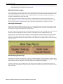
The Big Picture of Application Security................................................................................................ 34
Application Security...................................................................................................................34
Importing LDAP Users and User Groups.................................................................................. 34
3
Action Level Security.................................................................................................................34
Field Level Security................................................................................................................... 35
Encryption and Masking............................................................................................................ 35
The Base Package Controls One User, One User Group, And Many Application Services
..... 38
How To Copy User Groups From The Demonstration Database.............................................. 38
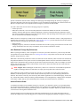
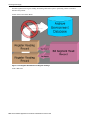
The Big Picture of Row Security........................................................................................................... 40
Access Groups, Data Access Roles and Users........................................................................... 41
Defining Application Services............................................................................................................... 41
Application Service - Main........................................................................................................ 41
Application Service - Application Security............................................................................... 42
Defining Security Types.........................................................................................................................42
Security Type - Main..................................................................................................................42
Defining User Groups............................................................................................................................ 43
User Group - Main..................................................................................................................... 43
User Group - Application Services............................................................................................ 44
User Group - Users.....................................................................................................................44
Defining Access Groups.........................................................................................................................45
Defining Data Access Roles...................................................................................................................45
Data Access Role - Main............................................................................................................45
Data Access Role - Access Group..............................................................................................46
Defining Users........................................................................................................................................46
User Interface Tools............................................................................................................47
Defining Menu Options..........................................................................................................................47
Menu - Main...............................................................................................................................47
Menu - Menu Items.................................................................................................................... 48
The Big Picture of System Messages..................................................................................................... 49
Defining System Messages........................................................................................................ 49
The Big Picture of Portals and Zones.....................................................................................................51
Portals Are Made Up of Zones...................................................................................................51
Zones May Appear Collapsed When a Page Opens...................................................................51
Changing Portal Preferences...................................................................................................... 52
Zones Appear By Default...........................................................................................................52
Granting Access to Zones.......................................................................................................... 52
Zone Type vs. Zone....................................................................................................................53
Fixed Zones versus Configurable Zones.................................................................................... 53
There Are Three Types of Portals.............................................................................................. 53
Common Characteristics of Stand-Alone Portals.......................................................................54
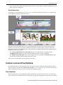
Custom Look and Feel Options..............................................................................................................55
User Interface............................................................................................................................. 55
UI Map Help...............................................................................................................................56
Setting Up Portals and Zones................................................................................................................. 56
Defining Zone Types..................................................................................................................56
Defining Zones........................................................................................................................... 57
Defining Context-Sensitive Zones............................................................................................. 60
Defining Portals..........................................................................................................................61
Defining Display Icons...........................................................................................................................62
Defining Navigation Keys......................................................................................................................63
Navigation Key Types................................................................................................................63
Navigation Key vs. Navigation Option...................................................................................... 63
The Flexibility of Navigation Keys............................................................................................63
Linking to External Locations....................................................................................................64
Overriding Navigation Keys...................................................................................................... 64
Maintaining Navigation Key...................................................................................................... 64
Defining Navigation Options................................................................................................................. 65
4
Navigation Option - Main.......................................................................................................... 66
Navigation Option - Tree........................................................................................................... 67
Defining COBOL Program Options.......................................................................................................67
COBOL Program - Main............................................................................................................68
Database Tools.................................................................................................................... 69
Defining Environment Reference Options............................................................................................. 69
Defining Table Options.......................................................................................................................... 69
Table - Main............................................................................................................................... 70
Table - Table Field..................................................................................................................... 71
Table - Constraints..................................................................................................................... 72
Table - Referred by Constraints................................................................................................. 73
Defining Field Options...........................................................................................................................73
Field - Main................................................................................................................................ 73
Field - Tables Using Field.......................................................................................................... 75
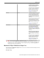
Defining Maintenance Object Options...................................................................................................75
Maintenance Object - Main........................................................................................................75
Maintenance Object - Options....................................................................................................76
Maintenance Object - Algorithms.............................................................................................. 76
Maintenance Object - Maintenance Object Tree........................................................................77
Defining Database Process Options....................................................................................................... 78
Database Process - Main............................................................................................................ 78
Database Process - DB Process Tree..........................................................................................79
Defining Database Process Instruction Options.....................................................................................79
Database Process Instruction - Main.......................................................................................... 79
Database Process Instruction - DB Process Instruction Tree..................................................... 82
Defining Look Up Options.....................................................................................................................82
Lookup - Main............................................................................................................................82
Defining Extendable Lookups................................................................................................................83
Extendable Lookup - Main.........................................................................................................83
The Big Picture Of Audit Trails............................................................................................................. 84
Captured Information................................................................................................................. 84
How Auditing Works................................................................................................................. 84
The Audit Trail File....................................................................................................................85
How To Enable Auditing........................................................................................................... 85
Audit Queries............................................................................................................................. 86
Bundling................................................................................................................................................. 88
About Bundling.......................................................................................................................... 88
Configuring Maintenance Objects for Bundling........................................................................ 89
Working with Bundles............................................................................................................... 91
Revision Control.................................................................................................................................... 93
About Revision Control............................................................................................................. 93
Working with Revision Control................................................................................................. 94
Working with Revision History................................................................................................. 96
To Do Lists...........................................................................................................................97
The Big Picture of To Do Lists.............................................................................................................. 97
To Do Entries Reference A To Do Type....................................................................................97
To Do Entries Reference A Role................................................................................................97
To Do Entries Can Be Rerouted (Or Suppressed) Based On Message Number........................98
The Priority Of A To Do Entry.................................................................................................. 99
Working On A To Do Entry.......................................................................................................99
Launching Scripts When A To Do Is Selected.......................................................................... 99
To Do Entries Have Logs...........................................................................................................99
How Are To Do Entries Created?............................................................................................ 100
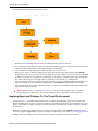
The Lifecycle Of A To Do Entry............................................................................................. 102
5
Linking Additional Information To A To Do Entry................................................................ 103
Implementing Additional To Do Entry Business Rules...........................................................104
To Do Entries May Be Routed Out Of The System.................................................................104
Periodically Purging To Do Entries......................................................................................... 104
Setting Up To Do Options....................................................................................................................105
Installation Options.................................................................................................................. 105
Messages.................................................................................................................................. 106
Feature Configuration.............................................................................................................. 106
Defining To Do Roles.............................................................................................................. 106
Defining To Do Types..............................................................................................................107
List of System To Do Types.................................................................................................... 111
Implementing The To Do Entries.............................................................................................111
Defining Background Processes.......................................................................................112
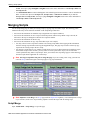
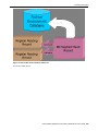
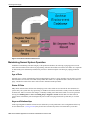
The Big Picture of Background Processes........................................................................................... 112
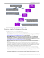
Background Processing Concepts............................................................................................ 112
Parameters Supplied To Background Processes...................................................................... 113
Processing Errors......................................................................................................................115
System Background Processes................................................................................................. 115
Submitting Batch Jobs..............................................................................................................115
Parallel Background Processes.................................................................................................117
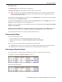
How to Re-extract Information................................................................................................ 119
How to Submit Batch Jobs....................................................................................................... 119
How to Track Batch Jobs......................................................................................................... 119
How to Restart Failed Jobs and Processes............................................................................... 119
Defining Batch Controls.......................................................................................................................119
The Big Picture of Requests.................................................................................................................121
Request Type Defines Parameters............................................................................................121
Previewing and Submitting a Request..................................................................................... 121
To Do Summary Email............................................................................................................ 121
Exploring Request Data Relationships.....................................................................................122
Defining a New Request.......................................................................................................... 122
Setting Up Request Types........................................................................................................ 122
Maintaining Requests............................................................................................................... 122
Defining Algorithms..........................................................................................................124
The Big Picture Of Algorithms............................................................................................................ 124
Algorithm Type Versus Algorithm.......................................................................................... 124
How To Add A New Algorithm...............................................................................................124
Minimizing The Impact Of Future Upgrades...........................................................................125
Setting Up Algorithm Types................................................................................................................ 125
List of Algorithm Types........................................................................................................... 126
Setting Up Algorithms......................................................................................................................... 126
Defining Script Options....................................................................................................128
The Big Picture Of Scripts................................................................................................................... 128
Scripts Are Business Process-Oriented.................................................................................... 128
A Script Is Composed Of Steps................................................................................................128
Designing And Developing Scripts..........................................................................................128
A Script May Declare Data Areas............................................................................................129
Designing Generic Scripts........................................................................................................129
Securing Script Execution........................................................................................................ 129
You Can Import Sample Scripts From The Demonstration Database..................................... 130
The Big Picture Of BPA Scripts.......................................................................................................... 130
How To Invoke Scripts............................................................................................................ 130
Developing and Debugging Your BPA Scripts........................................................................130
Launching A Script From A Menu.......................................................................................... 131
6
Launching A Script When Starting The System...................................................................... 131
Executing A Script When A To Do Entry Is Selected............................................................. 132
The Big Picture Of Script Eligibility Rules............................................................................. 132
Examples of BPA Scripts......................................................................................................... 136
The Big Picture Of Server-Based Scripts.............................................................................................160
Plug-In Scripts..........................................................................................................................160
Service Scripts..........................................................................................................................161
Debugging Server-Based Scripts............................................................................................. 162
How To Copy A Script From The Demonstration Database............................................................... 162
If You Work In A Non-English Language...............................................................................162
One Time Only - Set Up A DB Process To Copy Scripts........................................................163
Run The Copy Scripts DB Process.......................................................................................... 163
Maintaining Scripts.............................................................................................................................. 164
Script - Main.............................................................................................................................164
Script - Step.............................................................................................................................. 165
Script - Data Area.....................................................................................................................183
Script - Schema........................................................................................................................ 184
Script - Eligibility.....................................................................................................................184
Merging Scripts.................................................................................................................................... 186
Script Merge............................................................................................................................. 186
Resequencing Steps..................................................................................................................187
Removing a Step from Script................................................................................................... 187
Adding a Step to a Script..........................................................................................................188
Removing an Uncommitted Step from a Script....................................................................... 188
Maintaining Functions..........................................................................................................................188
Function - Main........................................................................................................................ 189
Function - Send Fields..............................................................................................................189
Function - Receive Fields.........................................................................................................190
Application Viewer........................................................................................................... 191
Application Viewer Toolbar.................................................................................................................191
Data Dictionary Button............................................................................................................ 191
Physical and Logical Buttons................................................................................................... 191
Collapse Button........................................................................................................................ 191
Attributes and Schema Button..................................................................................................192
Maintenance Object Button......................................................................................................192
Group and Ungroup List Buttons............................................................................................. 192
Algorithm Button..................................................................................................................... 192
Batch Control Button............................................................................................................... 192
To Do Type Button.................................................................................................................. 193
Description and Code Buttons..................................................................................................193
Cobol Source Button................................................................................................................ 193
Load Source Button..................................................................................................................193
Used By and Uses Buttons....................................................................................................... 194
Service XML Button................................................................................................................ 194
Select Service Button............................................................................................................... 194
Java Docs Button......................................................................................................................194
Classic Button.......................................................................................................................... 195
Preferences Button................................................................................................................... 195
Help Button.............................................................................................................................. 195
About Button............................................................................................................................ 195
Slider Icon................................................................................................................................ 195
Data Dictionary.................................................................................................................................... 195
Using the Data Dictionary List Panel.......................................................................................196
Using the Data Dictionary Detail Panel................................................................................... 196
7
Maintenance Object Viewer.................................................................................................................197
Using the Maintenance Object List Panel................................................................................ 198
Using the Maintenance Object Detail Panel............................................................................ 198
Algorithm Viewer................................................................................................................................ 198
Using the Algorithm Viewer List Panel................................................................................... 198
Using the Algorithm Plug-In Spot Detail Panel.......................................................................198
Using the Algorithm Type Detail Panel................................................................................... 199
Using the Algorithm Detail Panel............................................................................................ 199
Batch Control Viewer...........................................................................................................................199
Using the Batch Control Viewer List Panel............................................................................. 199
Using the Batch Control Detail Panel...................................................................................... 199
To Do Type Viewer..............................................................................................................................199
Using the To Do Type Viewer List Panel................................................................................ 200
Using the To Do Type Detail Panel......................................................................................... 200
Source Code Viewer.............................................................................................................................200
Using the Source Code Viewer List Panel............................................................................... 200
Using the Source Code Viewer Detail Panel........................................................................... 201
Service XML Viewer........................................................................................................................... 201
Using the Service XML Viewer Overview Panel.................................................................... 201
Using the Service XML Viewer Detail Panel.......................................................................... 201
Java Docs Viewer.................................................................................................................................201
Using the Java Docs Viewer List Panel................................................................................... 202
Using the Java Package Detail Panel....................................................................................... 202
Using the Java Interface / Class Detail Panel...........................................................................202
Application Viewer Preferences...........................................................................................................202
Application Viewer Stand-Alone Operation........................................................................................ 203
Stand-Alone Configuration Options.........................................................................................203
Example Application Viewer Configuration............................................................................204
Application Viewer Generation........................................................................................................... 204
Defining and Designing Reports...................................................................................... 206
The Big Picture Of Reports.................................................................................................................. 206
Integration with BI Publisher and Business Objects Enterprise.............................................. 206
How To Request Reports......................................................................................................... 208
Viewing Reports.......................................................................................................................208
Configuring The System To Enable Reports....................................................................................... 208
Configuring BI Publisher Reports............................................................................................208
Configuring Business Objects Enterprise Reports................................................................... 209
Defining Reporting Options..................................................................................................... 209
Defining Report Definitions.....................................................................................................210
Sample Reports Supplied with the Product..........................................................................................212
How to Use a Sample Report Provided with the System......................................................... 212
Subreports Used with Crystal Reports..................................................................................... 214
How To Define A New Report............................................................................................................ 215
Use a Sample Report as a Starting Point..................................................................................215
Publishing Reports in BI Publisher.......................................................................................... 216
Publishing Reports in Business Objects Enterprise................................................................. 216
Designing Your Report Definition........................................................................................... 217
External Application Integration.................................................................................... 220
Web Service Integration.......................................................................................................................220
Understanding Web Service Adapters..................................................................................... 220
Setting Up Web Service Adapters............................................................................................221
XML Application Integration...............................................................................................................222
The Big Picture of XAI............................................................................................................ 222
Designing Your XAI Environment.......................................................................................... 242
8
Schema Editor.......................................................................................................................... 256
Setting Up Your XAI Environment......................................................................................... 263
Maintaining Your XAI Environment....................................................................................... 281
How To.....................................................................................................................................286
Importing Users and Groups........................................................................................... 306
How Does LDAP Import Work?..........................................................................................................306
Invoking The Import Process................................................................................................... 306
Processing LDAP Import Requests..........................................................................................306
Setting Up Your System For LDAP Import.........................................................................................307
Defining a JNDI Server That Points to the LDAP Server........................................................307
Mapping Between LDAP Objects And Base Security Objects................................................307
Including Your LDAP Import Mapping in the Parameter Information Files.......................... 311
LDAP Import........................................................................................................................................311
Configuration Lab (ConfigLab)...................................................................................... 313
The Big Picture of ConfigLab.............................................................................................................. 313
Same Word, Two Meanings.....................................................................................................313
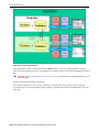
Pushing and Pulling Data Is Implemented Via Comparing..................................................... 313
The Compare Process Is Controlled By Metadata................................................................... 314
A Batch Control Must Exist..................................................................................................... 317
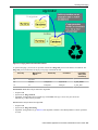
The Comparison Process Creates Root Objects....................................................................... 317
Applying Approved Changes To The Target Environment..................................................... 318
How To Compare Objects In Two Databases.......................................................................... 319
How To Copy Sample DB Processes From The Demonstration Database..............................319
Environment Management................................................................................................................... 320
Two Types Of Environments................................................................................................... 320
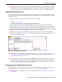
Registering Environments........................................................................................................ 321
Deregistering ConfigLab Environments.................................................................................. 321
Reregistering ConfigLab Environments...................................................................................322
Database Users......................................................................................................................... 322
Database Relationships............................................................................................................ 322
How To Register a ConfigLab Environment........................................................................... 325
Difference Query..................................................................................................................................330
Difference Query - Main.......................................................................................................... 330
Difference Query - Difference Query...................................................................................... 331
Root Object.......................................................................................................................................... 332
Root Object - Main...................................................................................................................332
Root Object - Data Differences................................................................................................ 333
Root Object - Root Object Tree............................................................................................... 333
Root Object Exception......................................................................................................................... 333
Archiving and Purging..................................................................................................... 335
The Big Picture of Archiving and Purging...........................................................................................335
Storing Archived Data..............................................................................................................335
Maintaining Normal System Operation................................................................................... 346
Metadata and Archive/Purge Procedures................................................................................. 347
Archive Engine.....................................................................................................................................352
Archive and Purge Procedures................................................................................................. 352
Lifecycle of an Archive Root Object....................................................................................... 357
Developing Archive and Purge Procedures......................................................................................... 358
Configure Metadata..................................................................................................................358
Design and Develop Criteria Algorithms and Table Rules......................................................358
Design and Develop Processing Algorithms............................................................................359
Design and Develop Archive Copy Processing Algorithms.................................................... 359
Sample Archive and Purge DB Processes............................................................................................359
How To Register an Archive Environment..............................................................................359
9
ArcSetup...................................................................................................................................362
Performance Tuning Tips For Archive.................................................................................... 363
How To Copy Samples From The Demonstration Database................................................... 363
Managing Archive Environments........................................................................................................ 365
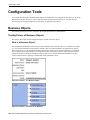
Configuration Tools.......................................................................................................... 368
Business Objects.................................................................................................................................. 368
The Big Picture of Business Objects........................................................................................368
Defining Business Objects....................................................................................................... 377
Business Services................................................................................................................................. 383
Defining Business Services...................................................................................................... 386
User Interface (UI) Maps..................................................................................................................... 387
Defining UI Maps.....................................................................................................................390
Maintaining Managed Content.............................................................................................................391
Managed Content - Main..........................................................................................................391
Managed Content - Schema..................................................................................................... 391
Data Areas............................................................................................................................................ 392
Defining Data Areas.................................................................................................................392
Schema Viewer.................................................................................................................................... 393
Business Event Log.............................................................................................................................. 393
Configuring Facts..............................................................................................................395
Fact Is A Generic Entity.......................................................................................................................395
Fact's Business Object Controls Everything........................................................................................ 395
Fact Supports A Log............................................................................................................................ 395
10
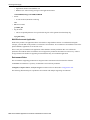
Overview
Overview
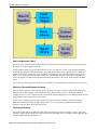
The Administration Guide describes how to implement and configure the Oracle Utilities Application Framework.
This includes:
Defining General Options on page 12
Access Groups, Data Access Roles and Users on page 41
User Interface Tools on page 47
Database Tools on page 69
To Do Lists on page 97
Defining Background Processes on page 112
Defining Algorithms on page 124
Defining Script Options on page 128
Application Viewer on page 191
Defining and Designing Reports on page 206
External Application Integration on page 220
Importing Users and Groups on page 306
Configuration Lab (ConfigLab) on page 313
Archiving and Purging on page 335
Configuration Tools on page 368
Configuring Facts on page 395
This guide contains the same content as the Framework Administration section of the online help.
Oracle Utilities Application Framework Administration User's Guide • 11
Defining General Options
Defining General Options
This section describes control tables that are used throughout your product.
Defining Installation Options
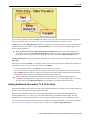
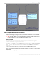
The topics in this section describe the various installation options that control various aspects of the system.
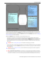
Installation Options - Main
Select Admin Menu > Installation Options > Installation Options - Framework to define system wide
installation options.
Description of Page
The Environment ID is a unique universal identifier of this instance of the system. When the system is installed, the
environment id is populated with a six digit random number. While it is highly unlikely that multiple installs of the
system at a given implementation would have the same environment ID, it is the obligation of the implementers to
ensure that the environment ID is unique across all installed product environments.
System Owner will be Customer Modification.
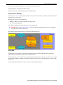
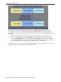
The Admin Menu Order controls how the various control tables are grouped on the Admin Menu.
•
•
If you choose Alphabetical, each control table appears under a menu item that corresponds with its first letter. For
example, the Language control table will appear under the L menu item entry.
If you choose Functional, each control table appears under a menu item that corresponds with its functional area.
For example, the Language control table will appear under the General menu item entry. Note, the menu that is
used when this option is chosen is the sole menu identified with a menu type of Admin.
Caution In order to improve response times, installation options are cached the first time they are used after
a web server is started. If you change the Admin Menu Order and you don't want to wait for the cache to
rebuild, you must clear the cached information so it will be immediately rebuilt using current information.
Refer to Caching Overview for information on how to clear the system login cache (this is the cache in which
installation options are stored).
The Language should be set to the language in which you work.
The Currency Code is the default currency code for transactions in the product.
If your product supports characteristics on its objects, define the date to be used as the Characteristic Default Date
on objects without an implicit start date. The date you enter in this field will default when new characteristics are
added to these objects (and the default date can be overridden by the user).
Active Owner displays the owner of newly added system data (system data is data like algorithm types, zone types,
To Do types, etc.). This will be Customer Modification unless you are working within a development region.
Country and Time Zone represent the default country and time zone that should be used throughout the application.
Turn on Seasonal Time Shift if your company requires seasonal time shift information to be defined.
12 • Oracle Utilities Application Framework Administration User's Guide
Defining General Options
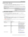
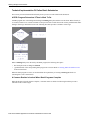
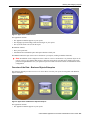
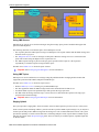
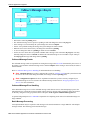
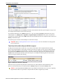
Installation Options - Messages
Select Admin Menu > Installation Options > Installation Options - Framework and the Messages tab to review
or enter messages that will appear throughout the application when a given event occurs.
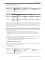
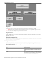
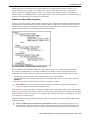
The Message collection contains messages that are used in various parts of the system. For each message, define the
Installation Message Type and Installation Message Text. The following table describes how the various Message
Types are used in the system.
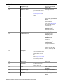
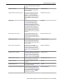
Message Type
How The Message Is Used
Company Title for Reports
This message appears as a title line on the sample reports
provided with the system. Generally it is your company name. It
is only used if you have installed reporting functionality and are
using the sample reports (or have designed your reports to use
this message).
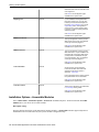
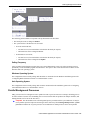
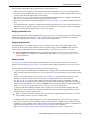
Installation Options - Algorithms
Select Admin Menu > Installation Options > Installation Options - Framework and the Algorithms tab to
review or enter the algorithms that should be evoked when a given event occurs.
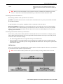
The grid contains Algorithms that control important functions in the system. You must define the following for each
algorithm:
•
•
Specify the System Event with which the algorithm is associated (see the table that follows for a description of all
possible events).
Specify the Sequence Number and Algorithm for each system event. You can set the Sequence Number to
10 unless you have a System Event that has multiple Algorithms. In this case, you need to tell the system the
Sequence in which they should execute.
Caution These algorithms are typically significant processes. The absence of an algorithm might prevent the
system from operating correctly.
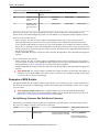
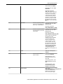
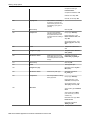
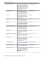
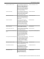
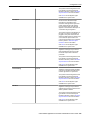
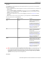
The following table describes each System Event.
System Event
Optional / Required
Geocoding Service
Optional
Description
Algorithms of this type use Oracle
Locator to retrieve latitude and longitude
coordinates using address information.
Click here to see the algorithm types
available for this system event.
Global Context
Optional
Algorithms of this type are called
whenever the value of one of the global
context fields is changed. Algorithms of
this type are responsible for populating
other global context values based on the
new value of the field that was changed.
Refer to Global Context Overview for
more information.
Click here to see the algorithm types
available for this system event.
Next To Do Assignment
Optional
This type of algorithm is used to find the
next To Do entry a user should work
on. It is called from the Current To Do
Oracle Utilities Application Framework Administration User's Guide • 13
Defining General Options
dashboard zone when the user ask for the
next assignment.
Click here to see the algorithm types
available for this system event.
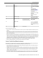
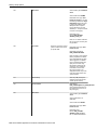
Reporting Tool
Optional
If your installation has integrated with a
third party reporting tool, you may wish
to allow your users to submit reports online using report submission or to review
report history online. This algorithm is
used by the two on-line reporting pages
to properly invoke the reporting tool from
within the system.
Click here to see the algorithm types
available for this system event.
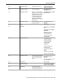
SMS Receive Service
Optional
This type of algorithm is used to provide
SMS receive service. Only one algorithm
of this type should be plugged in.
Click here to see the algorithm types
available for this system event.
SMS Send Service
Optional
This type of algorithm is used to provide
SMS send service. If your installation has
integrated with a third-party SMS service,
you may want to override this with your
own implementation. Only one algorithm
of this type should be plugged in.
Click here to see the algorithm types
available for this system event.
To Do Information
Optional
We use the term To Do information
to describe the basic information that
appears throughout the system to
describe a To Do entry.
Plug an algorithm into this spot to override
the system default "To Do information".
Click here to see the algorithm types
available for this system event.
To Do Pre-creation
Optional
These types of algorithms are called when
a To Do entry is being added.
Click here to see the algorithm types
available for this system event.
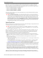
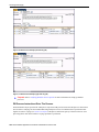
Installation Options - Accessible Modules
Select Admin Menu > Installation Options - Framework Installation Options - Framework and the Accessible
Modules tab to view the list of accessible modules.
Description of Page
This page displays the full list of the application's function modules. A Turned Off indication appears adjacent to a
module that is not accessible based on your system's module configuration setup.
14 • Oracle Utilities Application Framework Administration User's Guide
Defining General Options
Fastpath Refer to Module Configuration for more information on function modules and how to turn off
modules that are not applicable to your organization.
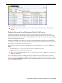
Installation Options - Installed Products
Select Admin Menu > Installation Options > Installation Options - Framework and the Installed Products tab
to view a read only summary of the products that are installed in the application version that you are logged into.
Description of Page
The Product Name indicates the name of the "products" that are installed. The collection should include
Framework, an entry for your specific product and an entry for Customer Release.
Release ID shows the current release of the application that is installed. This field is used by the system to ensure
that the software that executes on your application server is consistent with the release level of the database. If your
implementation of the product has developed implementation-specific transactions, you can populate the Release Id
for the Customer Release entry to define the latest release of implementation-specific logic that has been applied
to this environment. In order for this to work, your implementation team should populate this field as part of their
upgrade scripts.
The Release ID Suffix, Build Number and Patch Number further describe the details of your specific product
release.
The Display column indicates the product whose name and release information should be displayed in the title bar.
Only one product sets this value to Yes.
Owner indicates if this entry is owned by the base package or by your implementation ( Customer Modification).
Product Type indicates if the product is a Parallel Application. A parallel application is one that is independent of,
and does not conflict with, other parallel applications. Multiple parallel applications can be installed in the same
database and application server.
Note About Information. The information on this tab is used to populate the information displayed in the
About information for your product.
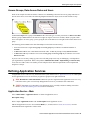
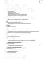
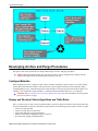
Support For Different Languages
User Language
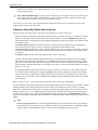
The system provides support for multiple languages in a single environment. System users can use the system in their
preferred language, as long as a translation into that language has been provided. By default, a user sees the system
in their default language (which is defined on their user record). Also note, if enabled, users can use the Switch
Language Zone to switch to another supported language real time.
Note Normally, setting up the system for another language is an implementation issue, not an administrative
set-up issue. However, there are several on-line administrative features that are used to set up a new language,
and these are described here.
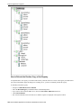
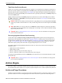
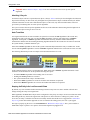
The following steps are required to support a new language.
•
•
Define a language code. Refer to Defining Languages for more information.
Copy descriptions of all language enabled tables from an existing translation. For example, you might copy
existing English language translations. These copied values are not meant to be used by system users, but act
Oracle Utilities Application Framework Administration User's Guide • 15
Defining General Options
merely as "placeholders" while they are being translated into the new language. It is necessary to do this as a first
step in order to create records using the new language code created in the previous step.
Language based descriptions can be copied using a supplied batch process, NEWLANG.
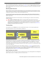
• Assign the new language code to your User ID, sign out, and sign back in again. Any on-line functions that you
access will use your new language code. (You can change the language code for all users who plan to use/modify
the new language).
• Begin translations. You might start with screen labels, menus, look-up values, and error messages. On-line utilities
have been provided to give you access to this system data. Refer to User Interface Tools and Database Tools
for more information. All administrative control tables are language enabled as well. The descriptions (short
descriptions, long descriptions, etc.) are all translatable.
Additional Topics
Your product may support additional uses for language. For example, in Oracle Utilities Customer Care and Billing,
you can define each customer's language. This allows you to send bills and other correspondence in each customer's
preferred language. For more information, navigate to the index entry Languages, Customer Language.
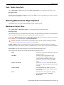
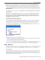
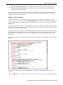
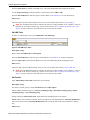
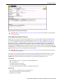
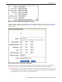
Defining Languages
A language code exists for every language spoken by your users. The system uses this code to supply information to
users in their respective language. Select Admin Menu > Language to define a language.
Description of Page
Enter a unique Language Code and Description for the language.
Turn on Language Enable if the system should add a row for this language whenever a row is added in another
language. For example, if you add a new currency code, the system will create language specific record for each
language that has been enabled. You would only enable multiple languages if you have users who work in multiple
languages.
The following two fields control how the contents of grids and search results are sorted by the Java virtual machine
(JVM) on your web server:
• The Locale is a string containing three portions:
• • ISO language code (lower case, required)
• ISO country code (upper case, optional)
• Variant (optional).
• Underscores separate the various portions, and the variant can include further underscores to designate multiple
variants. The specific JVM in use by your particular hardware/OS configuration constrains the available Locales.
Validating the Locale against the JVM is outside the scope of this transaction. This means you are responsible for
choosing valid Locales.
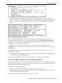
The following are examples of valid locales:
• en_US (this is for American English)
• en_AU (this is for Australian English)
• pt_BR (this is for Brazilian Portuguese)
• fr_FR_EURO (this is for European French)
• ja_JP (this if for Japanese)
In addition, the Java collation API can take a Collator Strength parameter. This parameter controls whether, for
example, upper and lower-case characters are considered equivalent, or how accented characters are sorted. Valid
values for collator strength are PRIMARY, SECONDARY, TERTIARY, and IDENTICAL. If you leave this field
blank, Java will use its default value for the language. We'd like to stress that the impact of each value depends on the
language.
16 • Oracle Utilities Application Framework Administration User's Guide
Defining General Options
Please see http://java.sun.com/j2se/1.3/docs/guide/intl/locale.doc.html for more information about the collator
strength for your language.
Display Order indicates if this language is written Left to Right or Right to Left.
Owner indicates if this language is owned by the base package or by your implementation ( Customer
Modification). The system sets the owner to Customer Modification when you add a language. This information is
display-only.
Where Used
Follow this link to open the data dictionary where you can view the tables that reference CI_LANGUAGE.
Note that all administrative control tables and system metadata that contain language-specific columns (e.g., a
description) reference a language code.
In addition, other tables may reference the language as a specific column. For example, on the User record you
indicate the preferred language of the user.
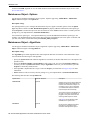
Defining Countries
The topics in this section describe how to maintain countries.
Country - Main
To add or review Country definitions choose Admin Menu > Country.
The Main page is used to customize the fields and field descriptions that will be displayed everywhere addresses are
used in the system. This ensures that the all addresses conform to the customary address format and conventions of
the particular country you have defined.
Description of Page
Enter a unique Country and Description for the country.
The address fields that appear in the Main page are localization options that are used to customize address formats
so that they conform to address requirements around the world. By turning on an address field, you make that field
available everywhere addresses for this country are used in the system. You can enter your own descriptions for the
labels that suffix each switch; these labels will appear wherever addresses are maintained in the system.
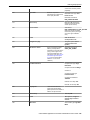
Note For any country where the State switch is checked, the valid states for the country must be entered on
the Country - State tab. When entering address constituents on a record that captures this detail, the value for
State is verified against the data in the State table. For any country where there is a component of the address
that represents a "state" but your implementation does not want to populate the valid states for that country,
choose a different field such as County for this constituent (and define an appropriate label). When entering
address constituents on a record that captures this detail, no validation is done for the County column.
Where Used
Follow this link to open the data dictionary where you can view the tables that reference CI_COUNTRY.
Country - States
To maintain the states located in a country, choose Admin Menu > Country and navigate to the State page.
Oracle Utilities Application Framework Administration User's Guide • 17
Defining General Options
Description of Page
For any country where you have enabled the State switch, use the State collection to define the valid states in the
Country.
•
•
Enter the standard postal abbreviation for the State or province.
Enter a Description for this state or province.
Defining Currency Codes
The currency page allows you to define display options related to currency codes that are used by your system. Use
Admin Menu > Currency Code to define the currency codes in which financial information is denominated.
Description of Page
Enter a unique Currency and Description for the currency.
Use Currency Symbol to define the character that prefixes currency amounts in the system (e.g., $ for U.S. dollars).
Enter the number of Decimals that will appear in the notation for the currency. For example, there are two decimal
positions for Australian dollars ($5.00), but no decimal positions in the Italian lira (500 L).
The Currency Position indicates whether the currency symbol should be displayed as a Prefix or a Suffix to the
currency amount. For example, the US Dollar symbol is a prefix before the amount ($5.00) and the French franc
symbol is a suffix after the amount (200.00FF).
Where Used
Follow this link to open the data dictionary where you can view the tables that reference CI_CURRENCY_CD.
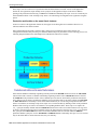
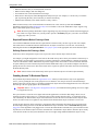
Defining Time Zones
The following topics describe how to design and set up time zones.
Designing Time Zones
Note Customer Care and Billing - Interval Billing applications customers should consult the topic Designing
Time Zones (search the CCB Help index for "time options") for specific information relating to CCB
functionality.
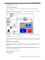
It is recommended that all time sensitive data is stored in the time of the base time zone as defined on the installation
options. This will prevent any confusion when analyzing data and will ensure that your algorithms do not have to
perform any shifting of data that may be stored in different time zones.
The Time Zone entity is used to define all the time zones where your customers may operate. It is used by interfaces
to help ensure data is stored correctly in the base time zone.
When designing your time zones, the first thing to determine is the base time zone. For an example, let's assume that
your company's main office is in the US Central time zone. First, you need to define this time zone and define the
seasonal time shift whose schedule it follows.
When designing your time zones, the first thing to determine is the base time zone. If, for example, your company's
main office and all customers are located in the US Central time zone, you would first you need to define this time
18 • Oracle Utilities Application Framework Administration User's Guide
Defining General Options
zone as well as the labels for standard time (default) and daylight savings time (shifted). Because (in this example) all
business occurs in the US Central time zone, no other time zone entries are required:
Time Zone
USCentral
Time Zone Name
US/Central
Default Label
CST
Shifted Label
CDT
Once this is done you can link the time zone code to the installation option as the base time zone. Refer to
Installation Options - Main for more information.
If your company does business beyond your local time zone, then you can define the other time zones where you may
have customers or other systems with which you exchange data. Let's use the US time zones as an example. We'll
define time zones for Eastern, Mountain, Pacific, and one for Arizona (which doesn't observe daylight savings time):
Time Zone
Time Zone Name
Default Label
Shifted Label
USCentral
US/Central
CST
CDT
USEastern
US/Eastern
EST
EDT
USMountain
US/Mountain
MST
MDT
USArizona
US/Arizona
AST
USPacific
US/Pacific
PST
PDT
Setting Up Time Zones
All time sensitive data will be stored according to the base Time Zone defined on the installation record. The time
zone table is used to define other time zones necessary for the application. When data being entered into the system
is related to a time zone other than that defined on the installation record, the time zone information may be used by
integration/interface logic to convert the data into the base time zone for storage on the database.
Open Admin Menu > Time Zone to define the time zones and their relation to the base time.
Description of Page
Enter a unique Time Zone and Description for the time zone.
Select the Time Zone Name from the list of Olson time zone values.
Indicate the Shift in Minutes that this time zone differs from the base time zone defined on the Installation Options
(for Customer Care and Billing - Interval Billing applications only).
Indicate the Seasonal Time Shift applicable for this time zone (for Customer Care and Billing - Interval Billing
applications only).
Default Time Zone Label is used to identify displayed and input times for non-shifted time. For example, the US/
Central label would be CST. If specified, this label must be different from the Default Time Zone Label.
Shifted Time Zone Label is used to identify displayed and input times when time is shifted (typically by daylight
savings time). For example, the US/Central label would be CDT.
Note Default Time Zone Label and Shifted Time Zone Label are used when you need to specify if a time
is shifted. For example, on a day when clocks are turned back one hour, a time entry of 1:30 a.m. needs to be
labeled as either 1:30 a.m. standard time or 1:30 a.m. daylight savings time. In the US/Central time zone this
would look like 13:30 CST or 13:30 CDT.
Where Used
Oracle Utilities Application Framework Administration User's Guide • 19
Defining General Options
Follow this link to open the data dictionary where you can view the tables that reference CI_TIME_ZONE.
Setting Up Seasonal Time Shift
Note The information in this topic applies only to Customer Care and Billing - Interval Billing applications.
Open Admin Menu > Seasonal Time Shift to define the seasonal time shift schedule.
Description of Page
Enter a unique Seasonal Time Shift code and Description for the seasonal time shift.
The Collection defines the Effective Date/Time (in standard time) that a time zone may shift in and out of standard
time. If time is changed from standard time on the effective date/time, enter the Shift in Minutes that the time
changes from standard time (usually 60). If the time is changed back to standard time on the effective date/time, enter
a Shift in Minutes of 0.
Where Used
Follow this link to open the data dictionary where you can view the tables that reference CI_SEAS_TM_SHIFT.
Defining Geographic Types
If your company uses geographic coordinates for dispatching or geographic information system integration, you need
to setup a geographic (coordinate) type for each type of geographic coordinate you capture on your premises and/or
service points (geographic coordinates can be defined on both premises and service points).
To define geographic types, open Admin Menu > Geographic Type .
Note Find a customer / premise using a geographic coordinate. In Oracle Utilities Customer Care and
Billing there are several queries that allow you to search for customers and premises by geographic type. For
example, Control Central and Meter Search allow you to search using the premise or service point geographic
type. Refer to the product documentation for more information.
Description of Page
Enter an easily recognizable Geographic Type code and Description.
Define the algorithm used to validate the Validation Format Algorithm. If an algorithm is specified, the system
will validate that the geographic location entered on the premise and/or service point for the geographic type is in the
format as defined in the algorithm. If you require validation, you must set up this algorithm in the system.
Click here to see the algorithm types available for this plug-in spot.
Where Used
Follow this link to open the data dictionary where you can view the tables that reference CI_GEO_TYPE.
Defining Work Calendar
Workday calendars are used to ensure system-calculated dates fall on a workday. Select Admin Menu > Work
Calendar to define a workday calendar.
20 • Oracle Utilities Application Framework Administration User's Guide
Defining General Options
Description of Page
The information on this transaction is used to define the days of the week on which your organization works.
Enter a unique Work Calendar and Description.
Turn on (check) the days of the week that are considered normal business days for your organization.
Use the collection to define the Holiday Date, Holiday Start Date, Holiday End Date, and Holiday Name for each
company holiday. Holiday Start Date and Holiday End Date define the date and time that the holiday begins and ends.
For example, your organization might begin a holiday at 5:00 p.m. on the day before the actual holiday.
Where Used
Follow this link to open the data dictionary where you can view the tables that reference CI_CAL_WORK.
Defining Display Profiles
When you set up your users, you reference a display profile. A user's display profile controls how dates, times, and
numbers displayed. Choose Admin Menu > Display Profile to maintain display profiles.
Description of Page
Enter a unique Display Profile ID and Description to identify the profile.
Enter a Date Format. This affects how users view dates and how entered dates are parsed. This is a "free format"
field with some rules.
• dd or d is interpreted as the day of the month. The d option suppresses a leading 0.
• MM or M is interpreted as the month number. The M option suppresses a leading 0.
• yyyy, yy, or y is interpreted as the year. The year can be 4 or 2 digits. The y option allows entry in either 2 or 4digit form and is displayed in 2-digit form.
Note For centuries, the default pivot for 2-digit years is 80. Entry of a 2-digit year greater than or equal to
80 results in the year being interpreted as 19xx. Entry of a 2-digit year less than 80 results in the year being
interpreted as 20xx.
•
•
tttt is interpreted as a year entered and displayed in Taiwanese format where 1911 is considered year 0000. Note
that the year is still stored in the database in Roman format. For example, if a date in the database is 01-01-2005, it
is displayed as 01-01-0094. If a user enters the date 02-02-0095, it is stored in the database as 02-02-2006.
Other characters are displayed as entered. Typically, these other characters should be separators, such as "-", ".",
or "/". Separators are optional; a blank space cannot be use.
Here are some examples of date formats.
Format
Displayed / entered as
MM-dd-yyyy
04-09-2001
d/M/yyyy
9/4/2001
yy.MM.dd
01.04.09
MM-dd-y
04-09-01 - in this case you could also enter the date as
04-09-2001
Enter a Time Format. This is a "free format" display with some rules.
• hh or h is interpreted as the hour, 1-12; KK or K is interpreted as the hour, 0-11; HH or H is interpreted as the
hour, 0-23; kk or k is interpreted as the hour, 1-24. The h, K, H, and k options suppress a leading 0.
Oracle Utilities Application Framework Administration User's Guide • 21
Defining General Options
•
•
•
mm or m is interpreted as the minutes. The m option suppresses a leading 0.
ss or s is interpreted as the seconds. The s option suppresses a leading 0.
a is interpreted to mean display am or pm (only needed when the hour is entered in hh, h, KK or K formats). If
an am or pm is not entered, it defaults to am.
Here are some examples of time formats.
Format
Displayed / entered as
hh:mma
09:34PM (can be entered as 09:34p)
hh:mm:ss
21:34:00
h:m:s
9:34:0
There are several options for displaying Numbers. Select the character you use as the Decimal Symbol (" ." or "
,"), the symbol that separates the integer and decimal parts of a number. Select the character you use as the Group
Symbol (" ,", " .", None or Space), i.e., the symbol used to separate 1000s. Select an option for the Negative Format,
which dictates how negative values are displayed: ‑9.9, (9.9), or 9.9-.
Currency values can have a different Negative Format from other numbers: -s9.9, (s9.9), or s9.9-, where the "s"
represents the currency symbol.
Where Used
Follow this link to open the data dictionary where you can view the tables that reference CI_DISP_PROF.
Defining Phone Types
Phone types define the format for entering and displaying phone numbers.
To add or review phone types, choose Admin Menu > Phone Type .
Description of Page
Enter a unique Phone Type and Description for each type of phone number you support.
Select an appropriate Phone Number Format Algorithm for each Phone Type. This algorithm controls the format
for entry and display of phone numbers. Click here to see the algorithm types available for this plug-in spot.
Use Phone Type Flag to define if this type of phone number is a Fax number. Defining which phone type is used for
facsimile transmittal is only pertinent if your product supports routing of information via fax. For example, in Oracle
Utilities Customer Care and Billing, the system may be configured to fax a bill to a customer.
Where Used
Follow this link to open the data dictionary where you can view the tables that reference CI_PHONE_TYPE.
Setting Up Characteristic Types & Values
If you need to introduce additional fields to objects that were delivered with minimal fields, you can add a
characteristic type for each field you want to capture. Using the characteristic type approach allows you to add new
fields to objects without changing the database. There are some pages in the system that support a generic list of
characteristics. For those pages, no changes are required for users to view and maintain characteristics. Other pages
22 • Oracle Utilities Application Framework Administration User's Guide
Defining General Options
are business object oriented pages and their maintenance and display are controlled by the UI maps defined for
the business objects. In those pages the display / maintenance of the characteristics are driven by the design of the
business object and its maps.
The topics in this section describe how to setup a characteristic type.
There Are Four Types Of Characteristics
Every characteristic referenced on an object references a characteristic type. The characteristic type controls the
validity of the information entered by a user when they enter the characteristic's values. For example, if you have
a characteristic type on user called "skills", the information you setup on this characteristic type controls the valid
values that may be specified by a user when defining another user's skills.
When you setup a characteristic type, you must classify it as one of the following categories:
•
•
•
•
•
•
•
Predefined value. When you setup a characteristic of this type, you define the individual valid values that may
be entered by a user. A good example of such a characteristic type would be one on User to define one or more
predefined skills for that user. The valid values for this characteristic type would be defined in a discreet list.
Ad hoc value. Characteristics of this type do not have their valid values defined in a discreet list because the
possible values are infinite. Good examples of such a characteristic type would be ones used to define a user's
birth date or their mother's maiden name. Optionally, you can plug-in an algorithm on such a characteristic type to
validate the value entered by the user. For example, you can plug-in an algorithm on a characteristic type to ensure
the value entered is a date.
Foreign key value. Characteristics of this type have their valid values defined in another table. For example
perhaps you want to link a user to a table where User is not already a foreign key. Valid values for this type of
characteristic would be defined on the user table. Please be aware of the following in respect of characteristics of
this type:
Before you can create a characteristic of this type, information about the table that contains the valid values must
be defined on the foreign key reference table.
The referenced table does not have to be a table within the system.
Not all entities that support characteristics support foreign key characteristics. Refer to the data dictionary to
identify the entities that include the foreign key characteristic columns.
File Location. Characteristics of this type contain a URL. The URL can point to a file or any web site.
Characteristics of this type might be useful to hold references to documentation / images associated with a given
entity. For example, the image of a letter sent to you by one of your customers could be referenced as a file
location characteristic on a customer contact entry. When such a characteristic is defined on an entity, a button can
be used to open the URL in a separate browser window.
Searching By Characteristic Values
For certain entities in the system that have characteristics, you may search for a record linked to a given characteristic
value. The search may be done in one of the following ways:
•
•
•
Some base searches provide an option to search for an object by entering Characteristic Type and Characteristic
Value.
Your implementation may define a customized search for an entity by a characteristic value for a specific
characteristic type using a query data explorer.
Your implementation may require a business service to find a record via a given characteristic value. For example,
maybe an upload of user information attempts to find the user via an Employee ID, defined as a characteristic.
Not all entities that support characteristics support searching by characteristics. Refer to the data dictionary to identify
the characteristic collections that include the search characteristic column.
Caution For ad-hoc characteristics, only the first 50 bytes are searchable. For foreign key characteristics, the
search value is populated by concatenating the values of each foreign key column to a maximum of 50 bytes .
Oracle Utilities Application Framework Administration User's Guide • 23
Defining General Options
For the base searches that provide a generic option to search by characteristic type and value, you can restrict the
characteristic types that can be used to search for an entity. For example, imagine you use a characteristic to define a
"jurisdiction" associated with a To Do for reporting purposes. If your company operates within a very small number
of jurisdictions, you wouldn't want to allow searching for a To Do by jurisdiction, as a large number of To Do entries
would be returned.
A flag on the characteristic type allows an administrator to indicate if searching by this characteristic type is allowed
or not allowed.
Characteristic Type - Main
To define a characteristic type, open Admin Menu > Characteristic Type.
Description of Page
Enter an easily recognizable Characteristic Type and Description for the characteristic type. Owner indicates if this
characteristic type is owned by the base package or by your implementation ( Customer Modification).
Caution Important! If you introduce a new characteristic type, carefully consider its naming convention.
Refer to System Data Naming Convention for more information.
Use Type of Char Value to classify this characteristic type using one of the following options (refer to There Are
Four Types Of Characteristics for more information):
•
•
•
Predefined value. Characteristics of this type have their valid values defined in the Characteristic Value scroll,
below. For each valid value, enter an easily recognizable Characteristic Value and Description. For example,
if you introduce a characteristic type to record the number of volts that are measured by a meter, you would add
values for all voltage levels measured by the meters utilized by your organization.
Ad hoc value. Characteristics of this type have an unlimited number of valid values. For example, if you use a
characteristic to define the date a meter was ordered, you'd use this classification because you can't define every
possible order date. If you use this option, you can optionally define the Validation Rule used to validate the
user-entered characteristic value. For example, if we carry on with our example, you'd use a validation rule to
make sure that what the user entered was actually a date. Click here to see the algorithm types available for this
plug-in spot.
File location value. Characteristics of this type contain a URL. The URL can point to a file or any web site.
Characteristics of this type might be useful to hold documentation / images associated with a given entity.
For example, the image of the formal contract signed by a customer could be referenced as a file location
characteristic on a service agreement. When such a characteristic value is defined on an entity, the value is
suffixed with a button that can be used to display the URL in a separate browser window.
Note File location characteristic values must be entered in a "non-relative" format. For example, if you
want to define a characteristic value of www.msn.com, you'd enter the characteristic value as http://
www.msn.com. If you omit the http:// prefix, the system will suffix the characteristic value to the current
URL in your browser and attempt to navigate to this location when the launch button is pressed (this may or
may not be the desired result).
•
Foreign key reference. Characteristics of this type have their valid values defined in another table. A good
example of such a characteristic type would be one used on a premise to define the premise's building manager.
Valid values for this type of characteristic would be defined on the person table (as you'd set up a person for the
building manager and then reference this person on the premise characteristic). If you choose this option, you
must use FK Reference to define the table that controls the valid values of this characteristic type. Refer to
Setting Up Foreign Key References for more information.
Use the Allow Search by Char Val to indicate if searching for an entity by this characteristic type is Allowed or Not
Allowed. Refer to Searching by Characteristic Values for more information.
Where Used
24 • Oracle Utilities Application Framework Administration User's Guide
Defining General Options
Use the Data Dictionary to view the tables that reference CI_CHAR_TYPE.
Characteristic Type - Characteristic Entities
To define the entities (objects) on which a given characteristic type can be defined, open Admin Menu >
Characteristic Type and navigate to the Characteristic Entities tab.
Description of Page
Use the Characteristic Entity collection to define the entities on which the characteristic type can be used. Owner
indicates if this is owned by the base package or by your implementation ( Customer Modification).
Note The values for this field are customizable using the Lookup table. This field name is
CHAR_ENTITY_FLG.
Note Heads up. For many entities in the system, the valid characteristics for a record are defined on a
related "type" entity. For example, in Oracle Utilities Customer Care and Billing the meter type defines valid
characteristics for meters of that type. When configuring your system, in addition to defining the appropriate
entity for a characteristic type, you may also need to link the characteristic type to an appropriate entity "type".
Setting Up Foreign Key Reference Information
A Foreign Key Reference defines the necessary information needed to reference an entity in certain table.
You need to set up this control table if you need to validate a foreign key value against a corresponding table. For
example, if a schema element is associated with an FK Reference the system validates the element's value against
the corresponding table. Refer to Configuration Tools to learn more about schema-based objects. Another example
is characteristics whose valid values are defined in another table (i.e., you use "foreign key reference" characteristic
types). Refer to There Are Four Types Of Characteristics for a description of characteristics of this type.
A FK Reference is used not just for validation purposes. It also used to display the standard information description of
the reference entity as well as provide navigation information to its maintenance transaction. Info descriptions appear
throughout the UI, for example, whenever an account is displayed on a page, a description of the account appears.
The above is possible as a result of information you define when you set up a foreign key reference for the table in
question. The following points describe what you should know before you can setup a foreign key reference for a
table.
• The physical name of the table. Typically this is the primary table of a maintenance object.
• The program used by default to construct the referenced entity's info description. Refer to Information
Description Is Dynamically Derived for more information on how this is used.
• The transaction used to maintain the referenced entity. This is where the user navigates to when using the "go to"
button or hyperlink associated with the entity. Refer to Navigation Information Is Dynamically Derived for more
information on how this is used.
• The name of the search page used to look for a valid entity. The system launches the search when a user presses
the search button that suffixes the characteristic value or column reference value. Typically, this will be the same
search page that's invoked from the table's maintenance page.
Information Description Is Dynamically Derived
Typically a FK Reference is defined for a maintenance object's primary table. In this case the system dynamically
derives the standard information associated with a specific referenced entity as follows:
• Attempt to determine the business object associated with the referenced entity. Refer to the Determine BO
maintenance object algorithm system event for more information. If a business object has been determined, the
system lets the business object's Information plug-in, if any, format the description.
Oracle Utilities Application Framework Administration User's Guide • 25
Defining General Options
•
•
If a business object has not been determined or the business object has no such plug-in, the system lets the
maintenance object's information plug-in, if any, format the description.
If the maintenance object has no such plug-in, the system uses the info program specified on the FK Reference to
format the description.
Note Technical note. For both Java and COBOL, the class / program that returns the information displayed
adjacent to the referenced entity is generated specifically for use as an info routine. Please speak to your
support group if you need to generate such a class / program.
Note Generic routine. The system provides a generic information routine that returns the description of
control table objects from its associated language table. By "control table" we mean a table with an associated
language table that contains a DESCR field. Refer to Defining Table Options for more information on tables
and fields. For COBOL, the name of the generic routine is Get Description Info. For Java, the java class is
com.splwg.base.domain.common.foreignKeyReference.DescriptionRetriever.
Navigation Information Is Dynamically Derived
Typically a FK Reference is defined for a maintenance object's primary table. In this case the system dynamically
derives the actual transaction to navigate to for a given referenced entity as follows:
•
•
Attempt to determine the business object associated with the referenced entity. Refer to the Determine BO
maintenance object algorithm system event for more information. If a business object has been determined, use
the maintenance portal defined as its Portal Navigation Option business object option.
If a business object has not been determined or the business object defines no such option, the system uses the
transaction specified on the FK Reference.
Foreign Key Reference - Main
To setup a foreign key reference, open Admin > Foreign Key Reference .
Caution Important! If you introduce a new foreign key reference, carefully consider its naming convention.
Refer to System Data Naming Convention for more information.
Description of Page
Enter an easily recognizable FK (foreign key) Reference code and Description for the table.
Enter the name of the Table whose primary key is referenced. After selecting a Table, the columns in the table's
primary key are displayed adjacent to Table PK Sequence.
Use Navigation Option to define the page to which the user will be transferred when they press the go to button or
hyperlink associated with the referenced entity. Refer to Navigation Information Is Dynamically Derived for more
information on how this is used.
The Info Program Type indicates whether the default program that returns the standard information description is
written in COBOL or Java.
•
•
If the Program Type is COBOL, use Info Program Name to enter the name of the COBOL program.
If the Program Type is Java, use Info Program Name to enter the Java class name.
Refer to Information Description Is Dynamically Derived for more information on the info program is used.
Note COBOL Programs. COBOL programs are not supported by all products.
Note View the source. If the program is shipped with the base package, you can use the adjacent button to
display the source code of this program in the source viewer or Java docs viewer.
Use Context Menu Name to specify the context menu that appears to the left of the value.
26 • Oracle Utilities Application Framework Administration User's Guide
Defining General Options
Use Search Navigation Key to define the search page that will be opened when a user searches for valid values. This
is only applicable for characteristics and column references.
Use Search Type to define the default set of search criteria used by the Search Navigation Key's search page.
Use Search Tooltip to define a label that describes the Search Navigation Key's search page.
Note Context Menu Name, Search Type and Search Tooltip. These attributes are only applicable to user
interface elements utilizing the foreign key compound element type. Report parameters that reference foreign
key characteristics are an example.
Where Used
Follow this link to open the data dictionary where you can view the tables that reference CI_FK_REF.
Defining Feature Configurations
A limited number of the system's features are configured by populating options on a "feature configuration". For
example, if your implementation uses Oracle Utilities Customer Care and Billing's batch scheduler, you must
populate a variety of options on the batch scheduler's feature configuration.
The administration documentation for each feature defines the impact of each option. The topics below simply
describe how to use this transaction in a generic way.
You can create features to control features that you develop for your implementation. To do this:
•
•
•
Define the new feature. You do this by adding a new lookup value to the EXT_SYS_TYP_FLG lookup field.
Define the feature's options. You do this by creating a new lookup field. The field must be in the format
xxxx_OPT_TYP_FLG where xxxx is the identifier of the EXT_SYS_TYP_FLG added above.
Flush all caches.
Feature Configuration - Main
To define your feature configuration, open Admin Menu > Feature Configuration .
Description of Page
Enter an easily recognizable Feature Name code.
Indicate the Feature Type for this configuration. For example, if you were setting up the options for the batch
scheduler, you'd select Batch Scheduler.
Note You can add new Feature Types. Refer to the description of the page above for how you can add
Feature Types to control features developed for your implementation.
Note Multiple Feature Configurations for a Feature Type. Some Feature Types allow multiple feature
configurations. The administration documentation for each feature will tell you when this is possible.
The Options grid allows you to configure the feature. To do this, select the Option Type and define its Value.
Set the Sequence to 1 unless the option may have more than value. Detailed Description may display additional
information on the option type.
Note Each option is documented elsewhere. The administration documentation for each feature describes its
options and whether an option supports multiple values.
Oracle Utilities Application Framework Administration User's Guide • 27
Defining General Options
Note You can add new options to base-package features. Your implementation may want to add additional
options to one of the base-package's feature types. For example, your implementation may have plug-in driven
logic that would benefit from a new option. To do this, display the lookup field that holds the desired feature's
options. The lookup field's name is xxxx_OPT_TYP_FLG where xxxx is the identifier of the feature on the
EXT_SYS_TYP_FLG lookup value. For example, to add new batch scheduler options, display the lookup
field BS_OPT_TYP_FLG.
Feature Configuration - Messages
If the feature exists to interface with an external system, you can use this page to define the mapping between error
and warning codes in the external system and our system.
Open this page using Admin Menu > Feature Configuration and navigate to the Messages tab.
Description of Page
For each message that may be received from an external system, define the Feature Message Category and Feature
Message Code to identify the message.
A corresponding message must be defined in the system message tables. For each message identify the Message
Category and Message Number. For each new message, the Message Category defaults to 90000 (because an
implementation's messages should be added into this category or greater so as to avoid collisions during upgrades).
Defining Master Configurations
A master configuration enables an implementation to capture various types of information in the system.
For example, a master configuration exists in the base product that captures the mapping between Hijri and Gregorian
dates. Given this, users are able to switch between Gregorian and Hijri date formats by changing the display profile
on their user record.
Master Configurations can be bundled for export to other environments.
Setting Up Master Configurations
To set up a master configuration, open Admin Menu > Master Configuration.
The topics in this section describe the base-package zones that appear on the Master Configuration portal.
Master Configuration
The Master Configuration List zone lists every category of master configuration.
The following functions are available:
•
•
Click a broadcast button to open other zones that contain more information about the adjacent master
configuration.
Click the Add/Edit button to start a business process that updates the master configuration.
Master Configuration Details
The Master Configuration Details zone contains display-only information about a master configuration.
This zone appears when a master configuration has been broadcast from the Master Configuration zone.
28 • Oracle Utilities Application Framework Administration User's Guide
Defining General Options
Please see the zone's help text for information about this zone's fields.
Miscellaneous Topics
The following sections describe miscellaneous system wide topics.
Module Configuration
The system provides the ability to simplify the user interface based on functionality areas practiced by your
organization.
Menu items and other user interface elements are associated with function modules. By default, all function modules
are accessible. If a function module is not applicable to your business you may turn it off. Refer to Turn Off A
Function Module for more information on how to turn off a module.
If a function module is made non-accessible, i.e. turned off, its related elements are suppressed from the user
interface. In addition the system may validate that related functionality is not accessed. This also means that turning
off the wrong module may cause any of the following to occur:
•
•
•
•
•
Menu items may not appear. Refer to Menu Item Suppression to better understand how menu item suppression
works.
Entire menus may not appear. Refer to Menu Suppression to better understand how menu suppression works.
Tabs on pages may not appear.
Fields may not appear.
The system may return an error message when you attempt to use a function (indicating the function is turned off).
To correct the above situation, simply remove the module from the turned off list thus making it accessible again.
Your module configuration setup is displayed on the installations record.
Menu Item Suppression
The following points describe how your module configuration can suppress menu items.
•
•
•
Menu items that are owned by the base product (as opposed to those your implementation adds) are associated
with one or more function modules. If your module configuration has turned off all of the menu item's modules,
the menu item is suppressed. If at least one of the modules is accessible, i.e. turned on, the menu item is not
suppressed.
If a menu line doesn't contain any accessible items, the menu line is suppressed.
If all lines on a menu are suppressed, the menu is suppressed when the menu button is clicked.
Menu Suppression
In addition to the above Menu Item Suppression logic, the following points describe how your module configuration
can suppress an entire menu.
•
•
Menus that are owned by the base product (as opposed to those your implementation adds) are associated with one
or more function modules.
If your module configuration has turned off all of the menu's modules, the entire menu is suppressed. If at least
one of the modules is accessible, i.e. turned on, the menu s not suppressed.
Turn Off A Function Module
The base package is provided with a Module Configuration Feature Configuration that allows your organization to
turn off base package function modules.
Oracle Utilities Application Framework Administration User's Guide • 29
Defining General Options
To turn off any of the base package function modules add a Turned Off option to this feature configuration
referencing that module. Refer to the MODULE_FLG lookup field for the complete list of the application's function
modules.
Any module not referenced on this feature configuration is considered turned on, i.e. accessible. To turn on a module,
simply remove its corresponding Turned Off option from this feature configuration.
You may view your module configuration setup on the installation options page.
Note Only one. The system expects only one Module Configuration feature configuration to be defined.
Global Context Overview
The framework web application provides each product the ability to nominate certain fields to act as a "global
context" within the web application. These fields are known as global context fields. For example, in Oracle Utilities
Customer Care and Billing, the global context fields are typically Account ID, Person ID and Premise ID. The values
of these fields may be populated as a result of searching or displaying objects that use these fields in their keys. If you
navigate to the Bill page and display a bill, the global context is refreshed with the Account ID associated with that
bill. The global context for Person ID and Premise ID are refreshed with data associated with that account.
Changing the values of the global context typically cause data displayed in zones on the dashboard to be refreshed to
show information relevant to the current values of these global context fields.
When the value of one of the global context fields changes, an algorithm plugged into the installation record is
responsible for populating the remaining global context values accordingly. Refer to your specific product for more
information about the base algorithm that is provided for that product.
Note Customer modification. If the global context values provided by your product do not satisfy your
implementation's business requirements, contact customer support for information on how to customize the
global context information.
System Data Naming Convention
There are several maintenance objects in the system that include owner flag in one or more if its tables. We refer
to the data in these tables as "system data". Some examples of system data tables include Algorithm Type, Batch
Control, Business Object and Script. Implementations may introduce records to the same tables. The owner flag for
records created by an implementation is set to CM (for customer modification), however the owner flag is not part of
the primary key for any of the system data tables. As a result, the base product provides the following guidelines for
defining the primary key in system data tables to avoid any naming conflict.
Base Product System Data
For any table that includes the owner flag, the base product will follow a naming convention for any new data that is
owned by the base product. The primary key for records introduced by the product is prefixed with x1- where x1 is
the value of the owner flag. For example, if a new background process is introduced to the framework product, the
batch code name is prefixed with F1-.
Note There are some cases where the hyphen is not included. For example, portal codes omit the hyphen.
For most system data, the remainder of the primary key is all in capital case. An exception is schema oriented records.
For business objects, business services, scripts, data areas and UI maps, the product follows the general rule of using
CapitalCase after the product owner prefix. For example, F1-AddToDoEntry is the name of a base product business
service.
30 • Oracle Utilities Application Framework Administration User's Guide
Defining General Options
Note Data Explorer Business Services. For business services used to invoke a data explorer Zone, it is
recommended to name the Business Service the same name as the related Zone rather than defining a different
CapitalCase name for the business service.
Please note that this standard is followed for all new records introduced by the base product. However, there are base
product entries in many of these system data tables that were introduced before the naming convention was adopted.
That data does not follow the naming convention described above.
Note Schema naming conventions. A context sensitive "Schema Tips" zone is associated with any page
where a schema may be defined. The zone provides recommended naming conventions for elements within
a schema along with a complete list of the XML nodes and attributes available to you when you construct a
schema.
Implementation System Data
When new system data is introduced for your implementation you must consider the naming convention for
the primary key. The product recommends prefixing records with CM, which is the value of the owner flag in
your environment. This is consistent with the base product naming convention. This convention allows your
implementation to use the CM packaging tool in the Software Development Kit as delivered. The extract file provided
with the tool selects system data records with an owner flag of CM AND with a CM prefix.
Note If you choose not to follow the CM naming convention for your records and you want to use the CM
packaging tool, your implementation must customize the extract file to define the appropriate selection criteria
for the records to be included in the package. Refer to the Software Development Kit documentation for more
information.
Also note that owner flag may be introduced to an existing table in a new release. When this happens, the CM
packaging tool is also updated to include these new system data tables. Your implementation will have existing
records in those tables that probably do not follow any naming convention. After an upgrade to such a release, if you
want to include this data in the CM packaging tool, you must customize the extract file for the tables in question.
Caching Overview
A great deal of information in the system changes infrequently. In order to avoid accessing the database every time
this type of information is required by an end-user, the system maintains a cache of static information on the web
server. In addition to the web server's cache, information is also cached on each user's browser.
Server Cache
The cache is populated the first time any user accesses a page that contains cached information. For example,
consider a control table whose contents appear in a dropdown on various pages. When a user opens one of these
pages, the system verifies that the list of records exists in the cache. If so, it uses the values in the cache. If not, it
accesses the database to retrieve the records and saves them in the cache. In other words, the records for this control
table are put into the cache the first time they are used by any user. The next user who opens one of these pages will
have the records for this control table retrieved from the cache (thus obviating the database access).
The following points describe the type of data that is cached on the web server:
•
•
•
•
•
Field labels. This portion of the cache contains the labels that prefix fields on the various pages in the system.
System information. This portion of the cache contains installation and basic information about the various
application services (e.g., the URL's that are associated with the various pages).
Menu items. This portion of the cache contains the menu items.
Dropdown contents. This portion of the cache contains the contents of the various dropdowns that appear
throughout the system.
XSL documents. This portion of the cache contains each page's static HTML.
Oracle Utilities Application Framework Administration User's Guide • 31
Defining General Options
•
Portal information. This portion of the cache contains information about which zones are shown on the various
pages.
The contents of the cache are cleared whenever the web server is "bounced". This means that fresh values are
retrieved from the database after the application server software is restarted.
If you change the database after the cache is built and the information you changed is kept in the cache, users may
continue to see the old values. If you don't want to bounce your web server, you can issue one of the following
commands in your browser's URL to immediately clear the contents of the cache (a separate command exists for each
type of data that is held in the cache):
•
•
•
•
•
•
•
•
•
flushAll.jsp?language=<language code>. This command flushes every cache described below.
flushMessageCatalog.jsp. This command flushes the field labels. Use this whenever you add or change any
labels (this is typically only done by implementers who have rights to introduce new pages).
flushSystemLoginInfo.jsp. This command flushes the system information cache. Use this whenever you change
navigation options, cached information from the installation record, or if you change an application service's URL.
flushMenu.jsp. This command flushes the menu cache. Use this command if you change menu data.
flushDropdownCache.jsp?language=<language code>. This command flushes ALL objects in the dropdown
contents associated with a given language (note, the language code is defined on the Language control table).
Use this whenever you change, add or delete values to/from control tables that appear in dropdowns. Unlike the
above caches, the objects in the dropdown cache are flushed automatically every 30 minutes from the time they
are first built.
flushDropDownField.jsp?language=<language code>&key=<field> If you want to flush the values in a
specific drop-down field in the cache, specify the <field> using this command.
flushUI_XSLs.jsp. This command flushes the XSL document cache. Use this command if you change user
interface meta-data. Also use this command whenever you change or introduce new zones.
flushXMLMetaInfo.jsp. This command flushes the XML repository of the XML Application Interface. Use this
command when your site's XAI configuration data needs to be updated, which should be a very rare occurrence.
flushPortalMetaInfo.jsp. This command flushes the portal information cache. Use this command whenever you
change any portal zone meta-data.
For example, assume the following:
•
•
the web server and port on which you work is called CD-Production:7500
you add a new record to a control table and you want it to be available on the appropriate transactions immediately
(i.e., you cannot wait for 30 minutes)
You would issue the following command in your browser's address bar: http://CD-Production:7500/
flushDropdownCache.jsp?language=ENG. Notice that the command replaces the typical cis.jsp that appears after
the port number (this is because these commands are simply different JSP pages that are being executed on the web
server).
Client Cache
In addition to the web server's cache, information is also cached on each user's browser. After clearing the cache that's
maintained on the web server, you must also clear the cache that's maintained on your client's browser. To do this,
follow the following steps:
•
•
•
•
•
Select Tools on your browser's menu bar
Select Internet Options... on the menu that appears.
Click the Delete Files button on the pop-up that appears.
Turn on Delete all offline content on the subsequent pop-up that appears and then click OK.
And then enter the standard URL to re-invoke the system.
Note Automatic refresh of the browser's cache. Each user's cache is automatically refreshed based on
the maxAge parameter defined in the web.xml document on your webserver. We recommend that you set
32 • Oracle Utilities Application Framework Administration User's Guide
Defining General Options
this parameter to 1 second on development / test environments and 28800 seconds (8 hours) on production
environments. Please speak to system support if you need to change this value.
Debug Mode
Your implementation team can execute the system using a special mode when they are configuring the application.
To enable this mode, enter ?debug=true at the end of the URL that you use to access the application. For example,
if the standard URL was http://CD-Production:7500/cis.jsp, you'd enter http://CD-Production:7500/cis.jsp?
debug=true to enable configuration mode.
When in this mode certain debugging oriented tools become available right below the main tool bar.
•
•
•
•
•
•
Start Debug starts a logging session. During this session the processing steps that you perform are logged. For
example, the log will show the data areas that are passed in at each step and the data areas returned after the step is
processed.
Stop Debug stops the logging session.
Show Trace opens a window that contains the logging session. All of the steps are initially collapsed.
Clear Trace clears your log file.
Show User Log allows you to view your own log entries. The number of "tail" entries to view may be specified in
the adjacent Log Entries field before clicking the button. Limiting the number of entries to view allows the user
to quickly and easily see only the latest log entries without having to manually scroll to the end of the log.
Checking the Global Debug indication starts various tracing options.
Other parts of the system may show additional configuration oriented icons when in this mode. For example, explorer
zones may provide additional tools to assist in debugging zone configuration. These icons are described in the context
of where they appear.
Also, in debug mode drop down lists in data explorer and UI map zones will contain the code for each item in
addition to the item's display string.
Note Show User Log button is secured. An application service F1USERLOG has been provided for this
functionality to allow implementations to restrict user access to this button. Such restriction may be called for
in production environments.
System Date Override
The system provides a way to override the system date used for online operations.
Under the General System Configuration Feature Configuration, the System Override Date Option Type holds
the date the application will use as the system date instead of retrieving the same from the database. This feature can
be especially useful in running tests that require the system date to be progressed over a period of time.
The system date override feature is also available at the user level.
Oracle Utilities Application Framework Administration User's Guide • 33
Defining Security & User Options
Defining Security & User Options
The contents of this section describe how to maintain a user's access rights.
The Big Picture of Application Security
The contents of this section provide background information about application security.
Application Security
The system restricts access to its transactions as follows:
• An application service exists for every securable function in the system. For example, an application service
exists for every transaction and zone in the system.
• You grant access to the application services to your user groups. For example, you may create a user group called
Senior Management and give it access to senior manager-oriented pages and portals.
• When you grant a user group access to an application service, you must also define the actions they can
perform. For example, you may indicate a given user group has inquire-only access to an application service,
whereas another user group has add, change, freeze, cancel and complete access to the same service. Refer to
action level security for more information.
• If the application service has field level security enabled, you must also define the user group's security level
for each secured field on the transaction.
• And finally, you link individual users to the user groups to which they belong. When you link a user to a user
group, this user inherits all of the user group's access rights.
Caution Menu items and menus may be suppressed! If a user doesn't have access to an application service, s/
he will not see the menu item that corresponds with the application service. And, if all menu items on a menu
are suppressed, the menu is suppressed.
Importing LDAP Users and User Groups
If your organization uses Lightweight Directory Access Protocol (LDAP), you can import your existing LDAP users
and groups into the system. Once imported, all user and group functions are available. You can import all users, a
group of users, or a single user. You can resynchronize your LDAP users and groups at any time.
For information on how to set up your system to import users and groups from an LDAP store as well as how to do
the import, refer to Importing Users and Groups.
Action Level Security
When you grant a user group access to an application service, you must indicate the actions to which they have
access.
• For application services that only query the database, there is a single action to which you must provide access this is called Inquire.
• For application services that can modify the database, you must define the actions that the user may perform. At
a minimum, most maintenance transactions support Add, Change, and Inquire actions. Additional actions are
available depending on the application service's functions.
Caution Important! If an application service supports actions that modify the database other than Add,
Change, and Delete; you must provide the user with Change access in addition to the other access rights.
Consider a transaction that supports special actions in addition to Add, Change, and Inquire (e.g., Freeze,
34 • Oracle Utilities Application Framework Administration User's Guide
Defining Security & User Options
Complete, Cancel). If you want to give a user access to any of these special actions, you must also give the
user access to the Inquire and Change actions.
Field Level Security
Sometimes transaction and action security is not sufficient. There are situations where you may need to restrict access
based on the values of data. For example, in Oracle Utilities Customer Care and Billing you might want to prevent
certain users from completing a bill for more than $10,000. This is referred to as "field level security".
Field level security can be complex and idiosyncratic. Implementing field level security always requires some
programming by your implementation group. This programming involves the introduction of the specific field-level
logic into the respective application service(s).
Note Field level security logic is added to user exits. Refer to the Public API chapter of the Software
Development Kit Developer Guide for more information on how to introduce field-level security logic into an
application service's user exits.
Even though the validation of a user's field-level security rights requires programming, the definition of a user's
access rights is performed using the same transactions used to define transaction / action level security. This is
achieved as follows:
•
•
•
•
Create a security type for each type of field-level security.
Define the various access levels for each security type. For example, assume you have some users who can
complete bills for less than $300, and other users who can complete bills for less than $1,000, and still other users
who can complete bills for any value. In this scenario, you'd need 3 access levels on this security type:
• Level 1 (lowest): May authorize bills <= $300
• Level 2 (medium): May authorize bills <= $1,000
• Level 3 (highest): May authorize all bills
Link this security type to each application service where this type of field level security is implemented. This
linkage is performed on the security type transaction.
Defining each user group's access level for each security type (this is done for each application service on which
the security type is applicable).
Note
Highest value grants highest security. The system expects the highest authorization level value to represent
highest security level. Moreover, authorization level is an alphanumeric field so care should be taken to ensure
that it's set up correctly.
Encryption and Masking
"Encryption" refers to encrypting data stored in a database using an encryption key.
Only users whose database access user ID has the appropriate encryption key can retrieve decrypted information.
Please refer to your database's encryption guidelines for how to encrypt data.
"Masking" refers to overwriting all or part of a decrypted field value with a masking character before it is presented
to a user (or an external system) without the appropriate security access. For example, an implementation can mask
the first 12 digits of a credit card number with an asterisk for users who do not have security rights to see credit card
numbers.
Multiple masking rules. The system allows different masking rules to be applied to different fields. For example,
a credit card number can be masked differently than a social security number. In addition, some user groups may be
allowed to see certain fields unmasked.
Oracle Utilities Application Framework Administration User's Guide • 35
Defining Security & User Options
Masking happens after decryption. It is obvious, but worth emphasizing, that only decrypted data can be masked.
This means that if a user does not have authority to retrieve decrypted data then masking is not relevant because the
data to be masked would be encrypted.
The topics in this section describe how to mask field values.
Identify the Fields to Be Masked
Your implementation should list every field on every page and XAI service request that requires masking
Classify each field into one of the following categories:
•
•
•
•
An element that is retrieved by invoking a business object, a business service, or a service script
A field that is retrieved by invoking a page service
A field that is retrieved by invoking a search service
An ad hoc characteristic type's value
Primary keys cannot be masked. A field defined as a unique identifier of a row cannot be configured for masking.
Masking a field that is part of the primary key causes a problem when attempting to update the record. This restriction
also applies to elements that are part of a "list" in a CLOB on a maintenance object. One or more elements in the
list must be defined as a primary identifier of the list. Be sure that primary key elements in the list are not ones that
require masking.
Masking applies to strings. Only fields with a data type of String can be masked.
List members that contain different "types". Consider a page with a list that contains a person's phone numbers.
You can set up the system so that a person's home phone has different masking rules than their work number. If your
implementation has this type of requirement, the list of masked fields should contain an entry for each masking rule.
Create a Security Type For Each Logical Field
Examine the list of masked fields and look for "logical fields".
For example, assume your list contains the following masked fields:
•
•
•
The Person - Main page retrieves information using the person page service. This page contains a grid that
contains the various forms of ID associated with the person. Entries in the grid with an ID Type of "Social
Security Number" are subject to masking.
The Control Central - Main page retrieves data by invoking a search service. This service shows a person's
primary form of ID in the search results. If a person's primary ID is their social security number then it is subject
to masking.
The Control Central - Account Information page contains a map zone that retrieves data by invoking a service
script. One of the elements in this script's schema holds the person's social security number and it is subject to
masking.
In the above example, there is a single "logical field" associated with the three secured elements: the social security
number.
Examine your list and define the distinct logical fields. For each one, create a security type with two authorization
levels:
•
•
1 - Can only see the element masked
2 - Can only see the element unmasked
You should link all of the security types to an application service of your choosing. We recommend linking every
masking-oriented security type to a single application service (e.g., CM_MASK) as it makes granting access easier.
36 • Oracle Utilities Application Framework Administration User's Guide
Defining Security & User Options
Create An Algorithm For Each Security Type
A masking algorithm must be created for each security type.
These algorithms determine if a user has the rights to view a given field unmasked, and, if not, how the field should
be masked.
The base package provides the algorithm type F1-MASK whose parameters are designed to handle most masking
needs. This algorithm type's parameters are described below to provide the complete picture of how to control how a
field is masked and who can see it unmasked:
•
•
•
•
•
•
Masking Character: Enter the character used to overwrite a field's value for users who can only see masked
values.
Number of Unmasked Characters: If some of the field value should remain unmasked at the end of the string,
enter the number of unmasked characters.
Unmasked Characters: If some characters in a field value should never be masked, enter them. For example, if a
phone number can contain dashes and parenthesis and you don't want these characters masked, you would enter ()..
Application Service: Enter the application service that you created above.
Security Type: Enter the security type that you created above.
Authorization Level: Enter the authorization level that a user must have to see this field unmasked. If you
followed the recommendations above, this will be 2.
Create A Feature Configuration For Each Secured Element
Create a feature configuration with a Feature Type of Data Masking.
Then add an option for every field that you defined in Identify The Fields To Be Masked.
Each field's option value will have an Option Type of Field Masking and a Value that references the respective
algorithm defined above. In addition, the Value will contain mnemonics that differ depending on how the field is
retrieved. For example, a field retrieved via a business object call has a different mnemonics than a field retrieved via
a page service call. Refer to the Detailed Description of the Field Masking option on the Feature Configuration page
for the mnemonic values required for each type of field.
Grant Access Rights To The User Groups
For each security type, identify which users can see its data unmasked and which users can only see its data masked.
If the masked and unmasked users fit into existing user groups, no additional user groups are necessary. Otherwise,
create new user groups for the masked and unmasked users.
After the user groups for each security type are defined, link each user group to the application service defined above.
When a user group is linked to the application service, you will define the authorization level for each security type
linked to the application service. If a user group's users should see the security type's field values unmasked, set the
authorization level to 2; otherwise set it to 1. Refer to User Group - Application Services for the transaction used to
link a user group to an application service.
Note Flush the cache. Remember that any time you change access rights you should flush the security cache
(by entering flushAll.jsp on the URL of the application) if you want the change to take affect immediately.
Additional Masking Information
The following points provide additional information to assist in your masking configuration:
Oracle Utilities Application Framework Administration User's Guide • 37
Defining Security & User Options
•
•
•
•
•
You should examine the Data Masking feature configuration in the demonstration system because it will
probably contain masking rules that will match your own.
On data input pages, a user might be able to enter or change masked data, such as a bank account number, but not
be able to subsequently see what they added or changed.
External systems can request information by performing a service call via XAI. Please keep in mind that some
XAI requests require data to be masked and some do not. For example, a request from an external system to
synchronize person information needs the person's social security number unmasked; whereas a request from a
web self service application to retrieve the same person information for display purposes needs the person's social
security number masked. To implement this type of requirement, different users must be associated with each of
the requests and these users must belong to separate user groups with different access rights.
If you need to mask a field value that is retrieved by invoking a business object (BO), a business service (BS),
or a service script (SS), the associated element in the invoked schema must be associated with a meta-data
field. It is this field's name that is referenced on the field's respective option value on the Data Masking feature
configuration. For example, if you need to mask a bank account number that's returned via a business object
call, the element in the schema that holds the bank account number must have either an mdField= attribute or a
mapField= attribute that references a field name (for example, BANK_ACCT). This is because when the option
value in the Data Masking feature configuration is defined, it references the BANK_ACCT field and not the
element name in the schema. Please note that if other BO, BS or SS schema elements reference this meta-data
field, the same masking rules will be applied.
If a maintenance object (MO) contains a CLOB field that holds an XML document and a service call invokes the
MO's service program directly, the system will mask individual XML elements in the CLOB if a Determine BO
algorithm has been plugged into the maintenance object and the element(s) in the respective BO schema have
been secured as described above.
The Base Package Controls One User, One User Group, And Many
Application Services
When the system is initially installed, the following information is setup:
•
•
•
•
Application services are created for all secured transactions in the base package.
A user identified by the user id SYSUSER is created.
A user group identified by the user group code ALL_SERVICES is created. This user group is associated with
all application services accessible from the Main and Admin menus. This user group is given access to all access
modes for all application services (i.e., all actions on all transactions).
The user SYSUSER is linked to the ALL_SERVICES user group. This means that this user has access to all
transactions and all actions.
When you receive an upgrade:
•
•
•
New application services are added for the new transactions introduced in the release.
Existing application services are updated with changes in their access modes (e.g., if a new action is added to a
transaction, its application service is updated accordingly).
The ALL_SERVICES user group is updated so it can access the new / changed application services.
Caution Important! With the exception of Field Level Security information, you should never add, change or
remove the above information. This information is owned by the base package. It is provided so that an "initial
user" has access to the entire system and can setup user groups and users as per your organization's business
requirements. In other words, do not provide your own users with access to the ALL_SERVICES user group.
In addition, if you introduce new transactions, do not add them to this user group. Rather, link them to the user
groups you setup to manage your organization's business requirements.
How To Copy User Groups From The Demonstration Database
Caution If you are not familiar with the concepts described in the ConfigLab chapter, this section will be
difficult to understand. Specifically, you need to understand how a Compare database process is used to copy
38 • Oracle Utilities Application Framework Administration User's Guide
Defining Security & User Options
objects between two databases. Please take the time to familiarize yourself with this concept before attempting
to copy a user group from the demonstration database.
Your product's demonstration database may contain sample user groups. These user groups reference logical
groups of application services. For example, the "case management user group" references the "case management"
application services.
You may find that these sample user groups closely match the user groups needed by your implementation. If this
proves true, you should copy these user groups from the demonstration database. This will save you time as you won't
have to set up the each such group's application services (but you'll still need to link your users to the appropriate user
groups). The topics in this section describe how to copy user groups from the demonstration database.
If You Work In A Non-English Language
The demonstration database is installed in English only. If you work in a non-English language, you must execute the
NEWLANG background process on the demonstration database before using it as a Compare Source supporting
environment. If you work in a supported language, you should apply the language package to the demonstration
database as well.
If you don't execute NEWLANG on the demonstration database, any objects copied from the demonstration
database will not have language rows for the language in which you work and therefore you won't be able to see the
information in the target environment.
One Time Only - Set Up A DB Process To Copy User Groups
You need a "copy user group" database process (DB process) setup in the target database (e.g., your
implementation's database). This DB process has a single instruction that references the user group maintenance
object (MO). This instruction should have a table rule with an override condition that selects the user groups in
question. For example, the override condition #SC_USER_GROUP.USR_GRP_ID LIKE 'CI_%' is used on
the DB process that copies user groups prefixed with CI_. The demonstration database contains such a DB process;
it's called CI_COPUG. In order to copy user groups from the demonstration database, you must first copy this DB
process from the demonstration database.
Caution The remainder of this section is confusing as it describes a DB process that copies another DB
process. Fortunately, you will only have to do the following once. This is because after you have a "copy
user groups" DB process in your target database, you can use it repeatedly to copy user groups from the
demonstration database.
You can copy the CI_COPUG DB process from the demonstration database by submitting the CL-COPDB
background process in your target database. When you submit this process, you must supply it with an environment
reference that points to the demonstration database. If you don't have an environment reference configured in your
target database that references the demonstration database, you must have your technical staff execute a registration
script that sets up this environment reference. Refer to Registering ConfigLab Environments for more information.
CL-COPDB is initially delivered ready to copy every DB process that is prefixed with CI_ from the source database
(there are numerous sample DB processes in the demonstration database and this process copies them all). If you only
want to copy the CI_COPUG DB process, add a table rule to the primary instruction of the CL-COPDB database
process to only copy the CI_COPUG DB process. The remainder of this section assumes you have added this table
rule.
When the CL-COPDB process runs, it highlights differences between the "copy user groups" DB process in your
source database and the target database. The first time you run this process, it creates a root object in the target
database to indicate the CI_COPUG DB process will be added to your target database. You can use the Difference
Query to review these root objects and approve or reject them.
Oracle Utilities Application Framework Administration User's Guide • 39
Defining Security & User Options
After you've approved the root object(s), submit the CL-APPCH batch process to change your target database. You
must supply the CL-APPCH process with two parameters:
•
•
The DB Process used to create the root objects ( CL-COPDB)
The environment reference that identifies the source database (e.g., the demonstration database)
Run The Copy User Groups DB Process
After you have populated the "copy user groups" DB process in your target database, you can override its table rule
to edit the list of user groups that will be copied. You need only do this if you don't need all of the user groups that are
defined in these DB processes (but it never hurts to have too many user groups as they won't be used unless you link
users to them).
At this point, you're ready to submit the background process identified on your "copy user group" DB processes. This
background process highlights the differences between the user groups in the demonstration database and the target
database (the target database is the environment in which you submit the background process).
Note The background process you submit is typically named the same as the DB process that contains
the rules. If you used the CL-COPDB background process to transfer the "copy user group" DB processes
from the demo database, it will have also setup these batch controls and linked to each the appropriate "copy
user groups" DB process. These batch controls have the same name as their related DB process (this is
just a naming convention, it's not a rule). This means, for example, that you'd submit a batch control called
CI_COPUG in order to execute the CI_COPUG DB process.
When you submit one of the DB processes defined above, you must supply it with an environment reference that
points to the source database (i.e., the demonstration database).
When the process runs, it simply highlights differences between the user groups in the source database and the
target database. It creates a root object in the target database for every user group that is not the same in the two
environments (actually, it only concerns itself with user group that match the criteria on the DB process's table rule
described above). You can use the Difference Query to review these root objects and approve or reject them.
Note Auto approval. When you submit the process, you can indicate that all root objects should be marked
as approved (thus saving yourself the step of manually approving them).
After you've approved the root object(s) associated with the user groups that you want copied, submit the CL-APPCH
batch process to cause your target database to be changed. You must supply the CL-APPCH process with two
parameters:
•
•
The DB process of the "copy user groups" DB process (e.g., CI_COPUG)
The environment reference that identifies the source database (i.e., the demonstration database)
The Big Picture of Row Security
Some products allow you to limit a user's access to specific rows. For example, in Oracle Utilities Customer Care and
Billing, row level security prevents users without appropriate rights from accessing specific accounts.
By granting a user access rights to an account, you are actually granting the user access rights to the account's bills,
payment, adjustments, orders, etc.
The topics in this section describe basic row level security objects.
Fastpath For a more detailed description of how row level security has been implemented in Oracle
Utilities Customer Care and Billing, refer to Administration Guide - Implementing Account Security in the
Customer Care and Billing documentation.
40 • Oracle Utilities Application Framework Administration User's Guide
Defining Security & User Options
Access Groups, Data Access Roles and Users
We'll use an example from Oracle Utilities Customer Care and Billing to describe how access groups and roles are
used to restrict access to accounts. The following diagram illustrates the objects involved with account security:
An Access Group defines a group of Accounts that have the same type of security restrictions. A Data Access Role
defines a group of Users that have the same access rights (in respect of access to accounts). When you grant a data
access role rights to an access group, you are giving all users in the data access role rights to all accounts in the access
group.
The following points summarize the data relationships involved with account security:
•
•
•
An account references a single access group. An access group may be linked to an unlimited number of
accounts.
A data access role has one or more users associated with it. A user may belong to many data access roles.
A data access role may be linked to one or more access group. An access group may be linked to one or more
data access roles.
If you use row level security, setting up your access roles and groups can be easy or challenging - it all depends on
your organization's requirements. Refer to the product's Administration Guide - Implementing Account Security
for several case studies. These case studies provide examples of how different requirements can be implemented
using these concepts.
Defining Application Services
An application service exists for every transaction in the system. Please refer to Application Security for a description
of how application services are used when you grant user groups access rights transactions.
Note Maintenance of this information is rare. The system is supplied with an application service for every
transaction in the system. You will only add application services if you introduce new transactions.
Caution Important! If you introduce a new application service, carefully consider its naming convention.
Refer to System Data Naming Convention for more information.
Application Service - Main
Select Admin Menu > Application Service to define an application service.
Description of Page
Enter a unique Application Service code and Description for the application service.
Indicate the application service's various Access Modes (i.e., actions). Refer to Action Level Security for more
information about the significance of these fields.
Oracle Utilities Application Framework Administration User's Guide • 41
Defining Security & User Options
Where Used
Follow this link to view the tables that reference the Application Service table in the data dictionary schema viewer.
Where Used
Follow this link to open the data dictionary where you can view the tables that reference SC_APP_SERVICE.
Application Service - Application Security
Use the Application Security portal to set up security for an application service.
Open this page using Admin Menu > Application Service , and then navigate to the Application Security tab.
This section describes the available zones on this page.
Application Service Details zone. The Application Service Details zone contains display-only information about the
selected application service, including the Access Modes for the application service and its security type.
User Groups with Access zone. The User Groups with Access zone lists the user groups that have access to the
application service. The following actions are available:
• Click the Description link to navigate to the User Group - Users page for the adjacent user group.
• Click Deny Access to remove the user group’s access rights from the selected Application Service.
• Use the search filters to display the user groups that contain a specific user.
User Groups without Access zone. The User Group without Access zone lists the user groups that do not have
access to the application service. The following actions are available:
• Click the Description link to navigate to the User Group - Users page for the user group.
• Click Grant Access to navigate to the User Group - Application Services page for the user group. The page is
automatically positioned at the selected application service.
• Use the search filters to display the user groups that contain a specific user.
Defining Security Types
Security types are used to define the types of field level security.
Note Programming is required. You cannot have field level security without introducing logic to user exits.
Refer to Field Level Security for more information on how security types are used to define field level security.
Security Type - Main
Select Admin Menu > Security Type to define your security types.
Description of Page
Enter a unique Security Type and Description.
Use the Authorization Level grid to define the different authorization levels recognized for this security type. Enter
an Authorization Level Number and its Description.
Note Programming is required. Note that the values that you enter are not interpreted by the system itself,
but by the user exit code used to implement the special security. Check with the developer of the user exit logic
for the correct values. Refer to Field Level Security for more information on how security types are used to
define field level security.
42 • Oracle Utilities Application Framework Administration User's Guide
Defining Security & User Options
Use the Application Services grid to define the application service(s) to which this security type is applicable. If this
application service is already associated with user groups, you must update each user group to define their respective
security level. This is performed using User Group - Application Service.
Where Used
Follow this link to open the data dictionary where you can view the tables that reference CI_SC_TYPE.
Defining User Groups
A user group is a group of users who have the same degree of security access. Think of a user group as a "role";
associated with a role are:
•
•
The users who play this role
The application services to which the role's users have access (along with the actions they can execute for each
service and their field level security authorization levels).
User Group - Main
Select Admin Menu > User Group to view the application services to which a user has access.
Caution Important! Please do not add, change or remove application services from the ALL_SERVICES
user group. Refer to The BasePackage Controls One User, One User Group, And Many Application Services
for an explanation.
Note Time saver. You can copy sample user groups from the demonstration database.
Description of Page
Enter a unique User Group code and Description for the user group.
Owner indicates if this user group is owned by the base package or by your implementation ( Customer
Modification). The system sets the owner to Customer Modification when you add a user group. This information is
display-only.
The Application Services grid displays the various application services to which users in this group have access.
Please note the following in respect of this grid:
•
•
•
•
Use the Application Service search to restrict the application services displayed in the grid. For example, if you
only want to see application services that start with the word "field", you can enter this word and press enter.
To add additional application services to this user group, navigate to the User Group - Application Services page
and click the + icon.
To remove or change this user group's access to an application service, click the go to button adjacent to the
respective application service. This will cause you to be transferred to the User Group - Application Services tab
where you should click the - icon to remove the application service from the user group.
Note, Owner indicates if this user group / application service relationship is owned by the base package or by
your implementation ( Customer Modification). The system sets the owner to Customer Modification when
you add an application service to the user group. This information is display-only.
Where Used
Follow this link to open the data dictionary where you can view the tables that reference SC_USER_GROUP.
Oracle Utilities Application Framework Administration User's Guide • 43
Defining Security & User Options
User Group - Application Services
Select Admin Menu > User Group and navigate to the Application Services tab to maintain a user group's access
rights to an application service.
Note Important! When you grant a user group access rights to an application service, you are actually
granting all users in the user group access rights to the application service.
Description of Page
The Application Service scroll contains the application services to which the User Group has access.
Note Note. You can also use Main page to select the application service for which you wish to change the
access privileges. To do this, simply click the go to button adjacent to the respective application service.
To add additional application services to this user group, click the + icon and specify the following:
•
•
Enter the Application Service ID to which the group has access.
Define the Expiration Date when the group's access to the application service expires.
Define the Access Modes that users in this group have to the Application Service. When a new application service
is added, the system will default all potential Access Modes associate with the Application Service. You need only
remove those modes that are not relevant for the User Group. Refer to Action Level Security for more information
about access modes.
Caution Important! If an application service supports actions that modify the database other than Add,
Change, and Delete; you must provide the user with Change access in addition to the other access rights.
Consider a transaction that supports actions in addition to Add, Change, and Inquire (e.g., Freeze, Complete,
Cancel). If you want to give a user access to any of these additional actions, you must also give the user access
to the Inquire and Change actions.
If you require additional security options, often referred to as "field level" security, then you use Security Type
Code and assign an Authorization Level to each. When a new application service is added, the system will display
a message indicating how many security types are associated with this application service. Use the search to define
each Security Type Code and indicate the appropriate Authorization Level for this user group. Refer to Field Level
Security for more information about security types.
User Group - Users
Select Admin Menu > User Group and navigate to the Users tab to maintain the users in a user group.
Description of Page
The scroll area contains the users who are part of this user group.
Note Keep in mind that when you add a User to a User Group, you are granting this user access to all of the
application services defined on the Application Services tab.
The following fields are included for each user:
•
•
•
Enter the User ID of the user.
Use Expiration Date to define when the user's membership in the group expires.
Owner will be Customer Modification.
Note Note. You can also add a user to a user group using User - Main.
44 • Oracle Utilities Application Framework Administration User's Guide
Defining Security & User Options
Defining Access Groups
Fastpath Refer to The Big Picture of Row Security for a description of how access groups are use to restrict
access to specific objects.
Access groups control which groups of users (referred to as Data Access Roles) have rights to accounts (or other
objects) associated with the access group. Select Admin Menu > Access Group to define your access groups.
Description of Page
Enter a unique Access Group code and Description for the data access group.
Use the Data Access Role collection to define the data access roles whose users have access to the access group's
accounts (or other objects). Keep in mind that when you add a Data Access Role to an Access Group, you are
granting all users who belong to this role access to all of the accounts (or other objects) linked to the access groups.
Refer to Access Groups, Data Access Roles and Users for more information.
Note You can also use Data Access Role - Access Group to maintain a data access role's access groups.
Where Used
Follow this link to open the data dictionary where you can view the tables that reference CI_ACC_GRP.
Defining Data Access Roles
Fastpath Refer to The Big Picture of Row Security for a description of how access groups are use to restrict
access to specific objects.
The data access role transaction is used to define two things:
• The users who belong to the data access role.
• The access groups whose accounts (or other objects) may be accessed by these users.
Data Access Role - Main
Select Admin Menu > Data Access Role to define the users who belong to a data access role.
Description of Page
Enter a unique Data Access Role code and Description for the data access role.
The scroll area contains the Users who belong to this role. A user's data access roles play a part in determining the
accounts (or other objects) whose data they can access. Refer to Access Groups, Data Access Roles and Users for
more information.
To add additional users to this data access role, press the + button and specify the following:
• Enter the User ID. Keep in mind that when you add a User to a Data Access Role, you are granting this user
access to all of the accounts (or other objects) linked to the data access role's access groups.
• Use Expiration Date to define when the user's membership in this data access role expires.
Note Also maintained on the user page. You can also use User - Access Security to maintain a user's
membership in data access roles.
Oracle Utilities Application Framework Administration User's Guide • 45
Defining Security & User Options
Where Used
Follow this link to open the data dictionary where you can view the tables that reference CI_DAR.
Data Access Role - Access Group
Select Admin Menu > Data Access Role and navigate to the Access Groups tab to define the access groups whose
accounts (or other objects) may be accessed by the users in this data access role.
Description of Page
Use the Access Group collection to define the access groups whose objects can be accessed by this role's users. Keep
in mind that when you add an Access Group to a Data Access Role, you are granting all users who belong to this
role access to all of the accounts (or other objects) linked to the access groups. Refer to Access Groups, Data Access
Roles and Users for more information.
Note You can also use Access Group - Main to maintain an access group's data access roles.
Defining Users
The user maintenance transaction is used to define a user's user groups, data access roles, portal preferences, default
values, and To Do roles. To access the user maintenance transaction, select Admin Menu > User .
The user maintenance transaction is the same transaction invoked when the user clicks on the preferences button;
the only difference is that when the user transaction is invoked from the Administration menu, all input fields are
updatable. When the transaction is invoked from the My Preferences Button, many fields are protected to prevent
end-users from changing important profile information. Please see the User Preferences page for a description of this
transaction.
Where Used
Follow this link to open the data dictionary where you can view the tables that reference SC_USER.
46 • Oracle Utilities Application Framework Administration User's Guide
User Interface Tools
User Interface Tools
This section describes tools that impact many aspects of the user interface.
Defining Menu Options
The contents of this section describe how you can add and change menus and Context Menus.
Caution Updating menus requires technical knowledge of the system. This is an implementation and delivery
issue and should not be attempted if you do not have previous experience with menus.
Note Security and menus. Refer to Application Security for a discussion of how application security can
prevent menu items (or an entire menu) from appearing.
Note Module configuration and menus. Your module configuration can prevent menu items (or an entire
menu) from appearing.
Menu - Main
This transaction is used to define / change any menu in the system. Navigate to this page using Admin Menu >
Menu .
Description of Page
Enter a meaningful, unique Menu Name.
Owner indicates if this menu line is owned by the base package or by your implementation ( Customer
Modification). The system sets the owner to Customer Modification when you add a menu line. This information is
display-only.
The Flush Menu button is used to flush the cached menu items so you can see any modified or newly created menus.
Refer to Caching Overview for more information.
Menu Type defines how the menu is used. You have the following options:
•
•
•
•
Enter Admin for the administration menu. The Admin menu is a special type of Main menu as admin menu
items can be grouped alphabetically or by functional group. Refer to the description of Admin Menu Order on
Installation Options - Base for more information about admin menu options.
Enter Context to define a context menu
Enter Main to define a menu that appears on the menu bar.
Enter Submenu to define a menu that appears when a menu item is selected. For example, the Main menu
contains numerous submenus. Each submenu contains the navigation options used to open a page.
Long Label is only enabled for Admin and Main menus. It contains the text displayed to identify the menu when the
menu button is clicked.
Menu Bar Description is only enabled for Admin and Main menus. It contains the text displayed to identify the
menu in the menu bar.
Sequence is only enabled for Admin and Main menus. It controls the order of the menu in the list of menus that
appears when the menu button is clicked.
Oracle Utilities Application Framework Administration User's Guide • 47
User Interface Tools
The grid contains a summary of the menu's lines. Refer to the description of Menu Items for how to add items to a
menu line.
• Menu Line ID is the unique identifier of the line on the menu. This information is display-only.
• Sequence is the relative position of the line on the menu. Note, if two lines have the same Sequence, the system
organizes the lines alphabetically (based on the Long Label, which is defined on the next tab).
• Navigation Option / Submenu contains information about the line's items. If the line's item invokes a submenu,
the submenu's unique identifier is displayed. If the line's item(s) invoke a transaction, the description of the first
item's navigation option is displayed.
• Long Label is the verbiage that appears on the menu line.
• Item Count is the number of menu items on the line.
• Owner indicates if this menu line is owned by the base package or by your implementation ( Customer
Modification). The system sets the owner to Customer Modification when you add a menu line. This
information is display-only.
Menu - Menu Items
After a menu has lines (these are maintained on the main tab), you use this page to maintain a menu line's items.
Each menu line can contain one or two menu items. The line's items control what happens when a user selects an
option on the menu.
There are two types of menu items: one type causes a transaction to be invoked when it's selected; the other type
causes a submenu to appear. For example,
• The following is an example of a menu line with two items: one opens the account transaction in update mode, the
other (the + icon) opens the account transaction in add mode:
•
The following is an example of a menu line with a single item that opens a submenu:
If you want to display an existing menu line's items:
• Navigate to Admin Menu > Menu and display the menu in question.
• Click the go to button on the line whose menu items should be displayed on this tab.
If you want to add a new line to an existing menu line:
• Navigate to Admin Menu > Menu and display the menu in question.
• Click the + button to add a new line to the grid.
• Use Sequence to specify the relative position of the line on the menu. Note, if two lines have the same Sequence,
the system organizes the lines alphabetically (based on the Long Label,which is defined on the next tab).
• Save the new line.
• Click the go to button on the new line.
Description of Page
Menu Name is the name of the menu on which the line appears. Menu Line ID is the unique identifier of the line
on the menu. Owner indicates if this menu is owned by the base package or by your implementation ( Customer
Modification). This information is display-only.
The Menu Line Items scroll contains the line's menu items. The following points describe how to maintain a line's
items:
• Menu Item ID is the unique identifier of the item.
• Owner indicates if this item is owned by the base package or by your implementation ( Customer Modification).
• If the menu item should invoke a submenu (as opposed to a transaction):
48 • Oracle Utilities Application Framework Administration User's Guide
User Interface Tools
•
•
•
•
•
•
•
•
•
• Use Sub-menu Name to identify the menu that should appear when the line is selected
• Use Long Label to define the verbiage that should appear on the menu line
If the item should invoke a transaction (as opposed to a submenu):
• Use Sequence to define the order the item should appear in the menu line (we recommend this be set to 1 or 2
as a menu line can have a maximum of 2 menu items).
• Use Navigation Option to define the transaction to open (and how it should be opened). Refer to Defining
Navigation Options for more information.
• If you want an icon to appear on the menu line (as opposed to text)
Use Image GIF Location and Name to define the location in which the icon resides on the web server. For
example, you could enter /images/contextAdd.gif if you want the classic "+" icon to appear. Your icons can
be located on the product's web server or on an external web server. To add a new icon to the product web
server, place it under the /cm/images directory under the DefaultWebApp. Then, in the URL field, specify the
relative address of the icon. For example, if the icon's file name is myIcon.gif, the URL would be /cm/images/
myIcon.gif. If the icon resides on an external web server, the URL must be fully qualified (for example, http://
myWebServer/images/myIcon.gif).
Use Image Height and Image Width to define the size of the icon.
Use Balloon Description if you want a tool tip to appear when the cursor hovers over the icon.
Use Long Label to describe what this menu item does (note, this won't appear on the menu because you are
specifying an icon; it's just good practice).
If you want text to appear on the menu line (as opposed to an icon), use Long Label to define the text.
The Override Label is provided in case you want to override the base-package's label.
Note Note. Owner indicates if this menu line is owned by the base package or by your implementation (
Customer Modification). The system sets the owner to Customer Modification when you add a menu line.
This information is display-only.
The Big Picture of System Messages
All error, warning and informational messages that are displayed in the system are maintained on the message table.
Every message is identified by a combination of two fields:
•
•
Message category number. Think of a message category as a library of messages related to a given functional
area. For example, there is a message category for billing messages and another one for payment messages.
Message number. A unique number identifies each message within a category.
Every message has two components: a brief text message and a long description. On the Main tab, you can only
maintain the brief message. If you need to update a message's long description, you must display the message on the
Details tab.
Note You cannot change the base package's text. If the message is "owned" by the base package,
you cannot change the base package's message or long description (if you could, your changes would be
overwritten during an upgrade). If you want your users to see a different message or long description other than
that supplied by the base package, display the message on the Details tab and enter your desired verbiage in the
"customer specific" fields (and flush the cache).
Defining System Messages
The contents of this section describe how to maintain messages that appear throughout the system.
Message - Main
Select Admin Menu > Message to maintain a message category and its messages.
Description of Page
Oracle Utilities Application Framework Administration User's Guide • 49
User Interface Tools
To add a new message category, enter a Message Category number and Description.
Note Note. Owner indicates if this message category is owned by the base package or by your
implementation ( Customer Modification). The system sets the owner to Customer Modification when you
add a category. This information is display-only.
Caution Message category 90000 or greater must be used to define new messages introduced for a specific
implementation of the system. Changes to other Message Text will be overwritten when you next upgrade. If
you want to make a change to a Message, drill down on the message and specify Customer Specific Message
Text.
To update a message, you must first display its Message Category. You can optionally start the message grid at a
Starting Message Number.
To override the message text or long description of messages owned by the base package, click on the message's go to
button. When clicked, the system takes you to the Details tab on which you can enter your implementation's override
text.
The following points describe how to maintain messages owned by your implementation:
•
•
•
•
Click the - button to delete a message.
Click the + button to add a new message. After clicking this button, enter the following fields:
Use Message Number to define the unique identifier of the message within the category.
Use Message Text to define a basic message. You can use the %n notation within the message text to cause field
values to be substituted into a message. For example, the message text The %1 non-cash deposit for %2 expires
on %3 will have the values of 3 fields merged into it before it is displayed to the user (%1 is the type of non-cash
deposit, %2 is the name of the customer, and %3 is the expiration date of the non-cash deposit).
Please note - the system merges whatever values are supplied to it. Therefore, if a programmer supplies a premise
address as the second merge parameter in the above message, this address is merged into the message (rather than the
customer's name).
•
•
•
Owner indicates if this message category is owned by the base package or by your implementation ( Customer
Modification). The system sets the owner to Customer Modification when you add a category. This information
is display-only.
Click the go to button to enter a longer explanation of the message. Clicking this button transfers you to the
Details tab.
To change a message, simply overtype its Message Text and save the category. Note, you must transfer to the
Details tab if you want to update a messages Description.
Where Used
Follow this link to open the data dictionary where you can view the tables that reference CI_MSG.
Message - Details
Select Admin Menu > Message and navigate to the Details tab to define detailed information about a message.
Note You don't have to use the scroll. Rather than scrolling through the messages, you can display a
message by clicking the respective go to button in the grid on the main tab.
Description of Page
The Message Collection scroll contains an entry for every message in the grid on the Main tab. It's helpful to
categorize messages into two categories when describing the fields on this page:
•
•
Base-package messages
Implementation-specific messages (i.e., a message added to Message Category 90000 or greater)
50 • Oracle Utilities Application Framework Administration User's Guide
User Interface Tools
For base-package messages, you can use this page as follows:
• If you want to override a message, specify Customer Specific Message Text.
• You are limited to the same substitution values used in the original Message Text. For example, if the original
Message Text is The %1 non-cash deposit for %2 expires on %3 and %1 is the type of non-cash deposit,
%2 is the name of the customer, and %3 is the expiration date of the non-cash deposit; your Customer Specific
Message Text is limited to the same three substitution variables. However, you don't have to use any substitution
variable in your message and you can use the substitution variables in whatever order you please (e.g., %3 can be
referenced before %1, and %2 can be left out altogether).
• If you want to override the long description of an error message, specify Customer Specific Description. Note
that the system does not present long descriptions when warnings are shown to users. Therefore, it doesn't make
sense to enter this information for a warning message.
For implementation-specific messages, you can use this page as follows:
• Use Message Text to define the message.
You can use the % n notation within the message text to cause field values to be substituted into a message.
For example, the message text The %1 non-cash deposit for %2 expires on %3 will have the values of three
fields merged into it before it is displayed to the user (%1 is the type of non-cash deposit, %2 is the name of the
customer, and %3 is the expiration date of the non-cash deposit).
Caution If both Message Text and Customer Specific Message Text are specified, the system will only
display the Customer Specific Message Text in the dialog presented to the user.
•
Use Description to define additional information about an error message. Note that the system does not present
long descriptions when warnings are shown to users. Therefore, it doesn't make sense to enter this information for
a warning message.
Caution If both Description and Customer Specific Description are specified, the system will only display
the Customer Specific Description in the dialog presented to the user.
The Big Picture of Portals and Zones
A portal is a page that is comprised of one or more information zones. Good examples of portals are those used by
most of us when we setup Yahoo, MSNBC, etc. for our own personal use. For example, in Yahoo, we can indicate we
want our portal to show zones containing our stock portfolio, the news headlines, and the local weather.
In your application, there are several pages that are made up of information zones. And, just like in Yahoo, users can
indicate which of these zones they want to see on each of the portal pages (and the order in which they appear).
The contents of this section describe how portals have been implemented in the system. Please see the specific
product documentation for information describing specific portals.
Portals Are Made Up of Zones
A "portal" is a page that contains one or more "zones" where each zone contains data of some sort. You define the
number and type of zones that can appear on a portal to match your implementation's requirements.
Note that not all zones must belong to a portal. Some zones exist that are used solely for internal processing by the
application. Also, zones used for pop-up help may not be linked to a portal.
Zones May Appear Collapsed When a Page Opens
When a portal opens, some or all of its zones may be collapsed (i.e., minimized) or open (i.e., the zone's content is
visible). To view the information in a collapsed zone, click the zone button
.
Oracle Utilities Application Framework Administration User's Guide • 51
User Interface Tools
Fastpath Refer to Allowing Users To Change Their Portal Preferences for important information describing
how users configure their zones.
Caution Recommendation. We strongly recommend that user preferences be set up to collapse zones that
aren't needed every time a portal is displayed. Why? Because the system does not perform processing until the
zone is expanded. In other words, indicating a zone is collapsed improves response times.
Changing Portal Preferences
Many portals supplied by the base product define several zone-oriented functions on the portal page and may not be
changed by an individual user. However, some portals are configured to allow users to define their preferences. A
user's Portal Preferences control several zone-oriented functions:
•
•
•
Which zones appear on their portal pages
The order in which the zones appear
Whether the zones should be "collapsed" (i.e., minimized) when the portal page opens
You can optionally configure the system to define portal preferences on one or more "template" users. If you link a
template user to a "real" user, the real user's preferences are inherited from the "template" user and the "real" user
cannot change their preferences. Some implementations opt to work this way to enforce a standard look and feel
throughout a user community.
If you don't do this, each user can change how their portals are organized and this may be exactly how you want to
work.
Zones Appear By Default
When you add a zone to a portal, and the portal has been configured to show on portal preferences, the system
assumes all users with access rights to the zone's application service should see it. This means that users don't have
to change their portal preferences in order to see newly added zones. If a user wants to suppress or reposition a zone,
they must change their portal preferences (if their portal preferences are not defined on a "template" user).
Note Adding a zone to a portal. You can add a zone to a portal using either Zone - Portal or Portal - Main.
Note Positioned at the bottom of the portal. If a user does not indicate where they want to see a zone (using
their portal preferences), the system positions it at the bottom of the portal. This means that if you add a zone
to a portal, it will appear at the bottom of the portal by default.
Granting Access to Zones
An application service is associated with each zone. A user must be granted access rights to the respective
application service in order to see a zone on a portal page.
Fastpath Refer to The Big Picture Of Application Security for information about granting users access rights
to an application service.
Please note the following in respect of how application security impacts a user's zones:
•
•
•
A user's Portal Preferences page contains a row for a zone regardless of whether the user has access rights to the
zone. Because of this, the system displays an indication of the user's access rights to each zone.
If a user's access rights to a zone are revoked, the zone will be suppressed when the user navigates to the
respective portal page.
Revoking a user's access rights does not change the user's portal preferences (i.e., a user can indicate they want
to see a zone even if they don't have access to the zone - such a zone just won't appear when the respective portal
page appears).
52 • Oracle Utilities Application Framework Administration User's Guide
User Interface Tools
Note If you don't need to use zone security. If your implementation gives all users access to all zones,
simply set up a single "dummy" application service and define it on all of your zones. This way, you only have
to grant security rights to this single application service to your user groups.
Zone Type vs. Zone
There are two meta-data objects that control how a zone is built: Zone Type and Zone (where a zone type can have
one or more zones):
• The Zone Type defines:
• The java class used to render its zones.
• The parameters whose values are configured on each of its zones. For example, a zone type that renders a graph
has parameters that control the type of data that appears in the graph, if the graph is animated, if the graph is
rendered using bars or lines, etc. Whenever you set up a zone of this type, you define the value of each of these
parameters. This means that you can have many graph zones that all reference the same zone type (where each
zone defines the type of data, if its animated, etc.).
• Optionally, parameter values used by the java class that are the same for all zones of a given type (this feature
simply saves the repetitive definition of these values on the zone types zones). A graph zone and a pie chart zone
are rendered using the same java class, however each zone uses a different XSL template (because pie charts look
very different from graphs). Rather than defining the XSL template on every graph zone, the graph zone type
holds a parameter value that defines the appropriate graph XSL template. The pie chart zone type holds a similar
parameter but its value references the XSL template used to build pie charts.
• Every Zone references a Zone Type. The Zone simply defines the parameter values for its zone type. For
example, you might have two graph zones - one graph shows expenses while the other shows revenue. Each of
these zones will reference the same zone type (the one that renders graphs) and unique parameter values to control
the type of data that it retrieves (one will indicate that revenue is retrieved, while the other indicates expenses are
retrieved).
Fixed Zones versus Configurable Zones
Some zone types are shipped with pre-configured zones that are linked to base-package portals. For example, the
base package is shipped with a Favorite Links zone that is linked to the Dashboard portal. For these zones, your
implementation simply needs to define your users' portal preferences and security rights. Please note, you cannot
change how these zones behave because their zone parameter values are owned by the base-package.
Other zone types have been designed to allow your implementation to control how their zones look and behave. For
example, the Timeline zone type allows your implementation to set up one or more timeline zones where each zone is
configured to show specific events. Follow these steps to introduce a configurable zone:
• Add the zone and configure its parameters as desired.
• Link the zone to the appropriate portal(s).
• Define your users' portal preferences and security rights in respect of the zone.
Please note that virtually every zone type supports implementation-specific zones.
Note "How to" hints. Each product-specific Administration Guide has a chapter that provides "tips and
techniques" on how the configurable zones can be used. Open the help and navigate to the index entry labeled
Configuring Zones.
There Are Three Types of Portals
There are three broad classes of portals:
• Standalone Portal. Standalone portals are separate pages. These pages are opened using any of the standard
methods (e.g., by selecting a menu item, by selecting a favorite link, etc.). Your implementation will add this
type of portal when necessitated by your users. For example, if you are implementing Oracle Utilities Business
Intelligence, you will set up portals as per the analytic requirements of your users (e.g., you might have one portal
Oracle Utilities Application Framework Administration User's Guide • 53
User Interface Tools
•
•
that contains zones showing revenue analytics, and another portal contains expense analytics). It should be noted
that no stand-alone portals are delivered with the base-package (your implementation must add these types of
portals).
Dashboard Portal. The dashboard portal is a portal that appears in the Dashboard Area on the users desktop.
Its zones contain tools and information that exist on the user's desktop regardless of the transaction. A good
example of a zone for this type of portal is one containing hyperlinks to the user's favorite transactions.
There is only one dashboard portal. This portal and several zones are delivered as part of the base-package. Your
implementation can add additional zones to this portal. Please contact customer support if you need to add zones
to the dashboard portal.
Tab Page Portals. You can add portals to base-package transactions. You would do this if you need to customize
how a transaction looks depending on the type of user. Please contact customer support if you need to add portals
to existing transactions.
Common Characteristics of Stand-Alone Portals
The topics that follow describe common characteristics of stand-alone portals. If you require information about
adding or changing Dashboard or Tab Page portals, please contact customer support.
Putting Portals on Menus
A stand-alone portal should appear as a menu item on one of your menus. The following points provide how to do
this:
•
•
•
•
Every stand-alone portal has an associated navigation option. You can see a portal's navigation option on the
Portal - Main page.
To add a portal to a menu, you must add a menu item to the desired menu. This menu item must reference the
portal's navigation option. There are two ways to add a menu item:
If the portal's navigation option doesn't currently exist on a menu, you can press the Add To Menu button on the
Portal - Main page. When you press this button, you will be prompted for the menu. The system will then create a
menu item on this menu that references the portal's navigation option.
You can always use the Menu page to add, change and delete menu items.
Note No limit. A portal's navigation option can appear on any number of menu items (i.e., you can create
several menu items that reference the same portal.
Note Favorite links. Your users can set up their preferences to include the portal's navigation option on their
Favorite Links. This way, they can easily navigate to the portal without going through menus.
Granting Access to A Portal
An application service is associated with each stand-alone portal. A user must be granted access rights to the
respective application service in order to see a portal.
Fastpath Refer to The Big Picture Of Application Security for information about granting users access rights
to an application service.
Note Automatically created. When you add a new stand-alone portal, the system automatically creates an
application service behind the scenes. You'll need to know the name of this application service as this is what
you use to grant access to the portal. The name of each stand-alone portal's application service is shown on the
portal transaction.
Please note the following in respect of how application security impacts a user's zones:
•
•
A user's Portal Preferences page only shows the portals configured to show on user preferences and where they
have security access.
The system's menus only show portals to which a user has security access.
54 • Oracle Utilities Application Framework Administration User's Guide
User Interface Tools
•
Users can set up favorite links to all portals, but they must have security rights to the portal's application service in
order to invoke the favorite link.
Portal Hierarchies
It is possible to create hierarchies of stand-alone portals. The following illustration shows three very simple Oracle
Utilities Business Intelligence stand-alone portals:
While each of the portals shown above can be opened independently, the sample zones shown on the High-level
Portal have been set up to have hyperlinks. When these hyperlinks are clicked, different portals are opened. The
destination portals have been configured to have zones that show more detailed information about the data shown on
the high-level objects. For example:
•
•
The Average Complaint Duration Traffic Light zone has been configured to have a hyperlink to the
Complaints Portal (which has zones that show many different analytics related to complaints).
The Total Revenue Traffic Light zone has been configured to have a hyperlink to the Revenue Portal (which
has zones that show many different analytics related to revenue).
There is no limit to the number of levels of portals you can have.
Custom Look and Feel Options
The default look and feel of the application can be customized via feature configuration and cascading style sheets.
The base package is provided with a Custom Look And Feel Feature Configuration type. You may want to set up a
feature configuration of this type to define style sheet and UI Map help options.
User Interface
The base package allows for the conditional inclusion of customer styles into the system style set. The custom style
may override any style provided by the base package. The style sheet may also include new styles for use in customer
Oracle Utilities Application Framework Administration User's Guide • 55
User Interface Tools
zone definitions. Use the Style Sheet option on the Custom Look And Feel Feature Configuration to define your
custom style sheet.
Note Note. Some styles cannot change if they are part of the HTML code.
Caution Implementers must ensure that the customized user interface is stable and scalable. Changing
font, alignment padding, border size, and other user interface parameters may cause presentation problems,
like scrollbars appearing or disappearing, cursors not working as expected, and unanticipated look and feel
alterations of some layouts.
UI Map Help
A tool tip can be used to display additional help information to the user. This applies to section elements as well
as individual elements on a map zone or UI Map. Refer to the tips context sensitive zone associated with the UI
Map page for more information. The Custom Look And Feel Feature Configuration provides options to control the
following:
•
•
•
Whether UI Map Help functionality is turned on of off. By default it is turned on.
Override the default help image with a custom image
The location of the help image, either before or after the element.
Fastpath Refer to the feature configuration for a detailed description of each option.
Setting Up Portals and Zones
The topics in this section describe how to set up portals and zones. Please refer to the The Big Picture of Portals and
Zones for background information.
Defining Zone Types
Select Admin Menu > Zone Type to maintain zone types.
Two types of parameters are specified when defining a zone type:
•
•
Parameter values that have a Usage of Zone are defined on the zones and control the functionality of each zone
governed by the zone type. A Usage value of Zone - Override Allowed indicates that override parameters for a
zone can be entered.
Parameter values that have a Usage of Zone Type are defined directly on the zone type and control how the zone
type operates (e.g., the name of the XSL template, the name of the application service). A Usage value of Zone
Type - Override Allowed indicates that override parameters for a zone can be entered.
Caution Do not remove or modify zone types provided with the base package, as base product zones will no
longer function. Additionally, this may introduce system instability.
Description of Page
Specify an easily recognizable Zone Type code and Description. Use the Long Description to describe in detail
what the zone type does.
Caution Important! When adding new zone types, carefully consider its naming convention. Refer to System
Data Naming Convention for more information.
Owner indicates if this zone type is owned by the base package or by your implementation ( Customer
Modification). The system sets the owner to Customer Modification when you add a zone type. This information is
display-only.
56 • Oracle Utilities Application Framework Administration User's Guide
User Interface Tools
Java Class Name is the Java class responsible for building the zone using the parameters defined below. The
following points describe the fields that are defined for each parameter:
•
•
•
•
•
•
•
Sequence defines the relative position of the parameter.
Parameter Name is the name of the parameter.
Description is a short description that allows you to easily identify the purpose of the parameter.
Comments contain information that you must know about the parameter or its implementation.
Usage indicates whether the parameter refers to a Zone or a Zone Type. Zone - Override Allowed and Zone
Type - Override Allowed indicate that override parameters for a zone can be entered.
Required is checked to indicate that a zone must define a value for the parameter. It is not checked if a value for
the parameter is optional. This field is protected if the Usage is Zone Type.
Parameter Value is used to define the value of zone type parameters. This field is protected if the Usage is Zone.
Note Note. Owner indicates if this parameter is owned by the base package or by your implementation (
Customer Modification). The system sets the owner to Customer Modification when you add a parameter.
This information is display-only.
Where Used
Follow this link to open the data dictionary where you can view the tables that reference CI_ZONE_HDL.
Defining Zones
The contents of this section describe how to maintain zones.
Zone - Main
Select Admin Menu > Zone to maintain a zone.
Caution Do not remove or modify zones provided with the base package, as this may produce indeterminate
results and may cause system instability.
Description of Page
Specify an easily recognizable Zone identifier and Description.
Caution Important! When introducing a new zone, carefully consider its naming convention. Refer to System
Data Naming Convention for more information.
Owner indicates if this zone is owned by the base package or by your implementation ( Customer Modification).
The system sets the owner to Customer Modification when you add a zone. This information is display-only.
Zone Type identifies the zone type that defines how the zone functions. The zone type's Long Description is
displayed below.
Application Service is the application service that is used to provide security for the zone. Refer to Granting Access
To Zones for more information.
The Width defines if the zone occupies the Full width of the portal or only Half.
Note Zones on the dashboard portal are always the width of the dashboard.
If the zone type supports help text, you can use Zone Help Text to describe the zone to the end-users. For example,
all Oracle Utilities Business Intelligence zone types can display help text when the zone's help button is clicked.
However help text cannot be displayed on Dashboard zones. Please refer to the section on zone help text for more
information on how you can use HTML and cascading style sheets to format the help text.
Use Override Zone Help Text to override the existing embedded help text for this zone.
Oracle Utilities Application Framework Administration User's Guide • 57
User Interface Tools
Note Viewing Your Text. You can press the Test button to see how the help text will look when it's
displayed in the zone.
The grid contains the zone's parameter values. The Zone Type controls the list of parameters. The grid contains the
following fields:
•
•
•
•
Description describes the parameter. This is display-only. Note that if there is a detailed description on the zone
type parameter, a question mark icon appears next to the parameter's description. Click the icon to see details
related to the parameter, including tips on how to populate the parameter value.
Parameter Value is the value for the parameter.
Use Override Parameter Value to override the existing value for this parameter. This field is enabled when the
related zone type parameter value is Zone - Override Allowed, and the zone is owned by the base product.
Owner indicates if this parameter is owned by the base package or by your implementation (Customer
Modification). This information is display-only.
Fastpath Business Intelligence zones. If this is a zone from Oracle Utilities Business Intelligence, you can
read about the various parameters and how they are used in the Configuring BI Zones chapter in that product's
Administration Guide.
Where Used
Follow this link to open the data dictionary where you can view the tables that reference CI_ZONE.
Zone - Portal
Select Admin Menu > Zone and navigate to the Portal tab to define the portals on which a zone appears.
Description of Page
The scroll area contains the portals on which the zone appears.
To add a zone to a portal, press the + button and specify the Portal. Refer to Zones Appear By Default for how newly
added zones are shown to users.
Note Note. Owner indicates if this portal / zone relationship is owned by the base package or by your
implementation ( Customer Modification). This information is display-only.
Note You can also add a zone to a portal using Portal - Main.
Zone How To Guide
The topics in this section provide tips and techniques to assist you in setting up your zones.
How to Add a New Zone
The steps necessary to add a new zone depend on the zone's zone type. For example, if you want to add a new zone
that references one of the Oracle Utilities Business Intelligence zone types, no programming is necessary (you simply
add a new zone using the above transaction the zone's parameters).
However, if you need to add a new zone with an idiosyncratic service or user interface, you must involve a
programmer. Let's use an example to help clarify what you can do versus what a programmer must do. Assume that
you want to add a new account characteristics zone to Oracle Utilities Customer Care and Billing. To do this you
must:
•
•
Create a new service that retrieves the data to appear in your zone.
Create a new XSLT template file (or reuse an existing one) that formats the data.
58 • Oracle Utilities Application Framework Administration User's Guide
User Interface Tools
•
•
•
Set up the appropriate zone type meta-data. The zone type will reference a Java class that is responsible for taking
the data from your service and applying an XSL template to generate the HTML fragment that displays in the
zone.
Create a zone called Account Characteristics (or something similar). On this zone, define the name of the
service that you created above. You'd also define the various parameter values required by the zone type, such
as the service name, XSLT template location, and key fields. If we assume that your account characteristics zone
needs to know the account ID, you'd indicate ACCT_ID as one of your key parameter values.
After creating the new zone, you can reference it on a portal or as a context-sensitive zone or both.
If you want to create more complex zones, you have two options:
• You can use the simple zone type that passes through any HTML fragment that you want to display. In your
HTML fragment, you can use an iframe and/or JSP to do the complicated data processing and formatting.
• If the simple zone type will not work for your needs, you may need to create your own zone type.
Fastpath For more information about developing services and zones, refer to the Software Development
Kit Developer Guide.
Zone Help Text
Some zone types support a button that allows a user to see zone-specific help text. For example, many Oracle Utilities
Business Intelligence zones support this functionality.
If your zone types support help text, you can define this text on the zone page.
You can use HTML tags in the zone help text. The following is an example of help text that contains a variety of
HTML tags:
This zone summarizes <font color=blue><b>revenue</b></font> in 4 periods:<br>
The above would cause the word revenue to be bold and blue:
• <b> and </b> are the HTML tags used to indicate that the surrounded text should be bold
• <font color=blue> and </font> are the HTML tags used to indicate that the surrounded text should be blue.
The following are other useful HTML tags:
• <br> causes a line break in a text string. If you use <br><br> a blank line will appear.
• <I> causes the surrounded text to be italicized
Please refer to an HTML reference manual or website for more examples.
You can also use "spans" to customize the look of the contents of a text string. For example, your text string could be
<span style="font-family:Courier; font-size:large; font-weight:bold;">revenue</span>. This would make the
word "revenue" appear as large, bold, Courier text. Please refer to a Cascading Style Sheets (CSS) reference manual
or website for more examples.
The following is an example of help text using a variety of HTML tags:
<font FACE="arial" size=2>
This zone summarizes <font color=blue><b>revenue</b></font> in 4 periods:<br>
- The <b>1st period</b> is under your control. You simply select the desired <b>Period</b>, above <i>(you may
need to click the down arrow to expose the filter section)</i><br>
- The <b>2nd period</b> is the period before the 1st period<br>
- The <b>3rd period</b> is the same as the 1st period, but in the previous year<br>
- The <b>4th period</b> is the period before the 3rd period<br>
Oracle Utilities Application Framework Administration User's Guide • 59
User Interface Tools
<br>
The traffic light's color is determined as follows:<br>
- The ratio of the 1st and 3rd period is calculated<br>
- If this value is between 80 and 100, <font color=orange><b>yellow</b></font> is shown<br>
- If this value is < 80, <font color=red><b>red</b></font> is shown<br>
- If this value is > 100, <font color=green><b>green</b></font> is shown<br>
- If the value of the 3rd period is 0, no color is shown<br>
</font>
Note It is possible to associate tool tip help with individual HTML and UI map elements. For more
information, see UI Map Help.
Maintaining Embedded Help
Embedded Help is the help text that is available to users on the fields of the application.
You can use the Embedded Help portal to create or override the help text that appears on the fields in a UI Map. Open
this page using Admin > Embedded Help.
Description of Page
Use the UI Map Search zone to search for the UI Map. You can search by UI Map name, Description, Business
Object name, or Business Object Description. The Business Object search filters will only display UI maps that are
defined on a business object’s options.
In the search results table the following actions are available:
• Click the Description link to go to the associated UI Map’s maintenance page.
• Click Edit to open the Embedded Help Authoring page. The following actions are available on this page:
• You can edit the Label and Help Textfields if the system owner is the same as the field owner.
Note Do not edit the Label or Help Text fields for fields supplied in the base package.
•
•
•
•
•
•
•
You can edit the Override Label and Override Help Text fields if the system owner is not the same as the
field owner. The values in these fields will override the existing label and help text.
All disabled fields will have their text prefixed with "(PROTECTED)."
Click Save to save your changes.
Click Close to close the page.
Click Download to CSV File to create a file that contains the fields and their values. You can use this file for
authoring the embedded help.
Click Browse to locate a CSV file that you would like to upload.
Click Upload to upload a CSV file. When you upload the file your new label and help text values will be
saved to the system.
Defining Context-Sensitive Zones
A context-sensitive zone allows you to associate a zone with a specific user-interface transaction. A context-sensitive
zone appears at the top of the Dashboard when a user accesses a page for which the zone is specified as the context.
For example, if you create an Account Characteristics zone and add it as a context-sensitive zone to the Account
Maintenance page it appears in the Dashboard whenever a user accesses the Account Maintenance page.
60 • Oracle Utilities Application Framework Administration User's Guide
User Interface Tools
Caution Make sure that the zone is appropriate for the transaction on which you are specifying it. For
example, if your zone requires an account ID as one of its keys, you would not display it on the Meter Read
transaction.
Select Admin Menu > Context Sensitive Zone to maintain context-sensitive zones.
Description of Page
The Navigation Key is a unique identifier of a tab page within the system. Owner indicates if this navigation key is
owned by the base package or by your implementation ( Customer Modification).
Caution Important! When introducing a new context sensitive zone, carefully consider its naming
convention. Refer to System Data Naming Convention for more information.
The grid contains the list of context-sensitive zones and the sequence in which they appear in the dashboard for the
selected navigation key. The grid contains the following fields:
• Zone is the name of the zone to display in the Dashboard.
• Sequence is the sequence in which the zone is displayed (if multiple context-sensitive zones are defined).
• Owner indicates if this context sensitive zone is owned by the base package or by your implementation (
Customer Modification).
Where Used
A context-sensitive zone displays at the top of the Dashboard whenever a user accesses the transaction for with the
zone is specified.
Defining Portals
This transaction is used to define / change portals. Navigate to this page using Admin Menu > Portal .
Description of Page
Enter a meaningful and unique Portal code and Description. Please be aware that for stand-alone portals, the
Description is the portal page's title (i.e., the end-users will see this title whenever they open the portal).
Caution Important! When introducing a new portal, carefully consider its naming convention. Refer to
System Data Naming Convention for more information.
Owner indicates if this portal is owned by the base package or by your implementation ( Customer Modification).
The system sets the owner to Customer Modification when you add a portal. This information is display-only.
Type flag indicates whether the portal is a Standalone Portal, a Tab Page Portal or the Dashboard. Refer to There
Are Three Types of Portals for more information.
The following fields are only enabled for Standalone Portals:
• Navigation Option defines the navigation option that is used to navigate to this portal from menus, scripts and
your favorite links. The navigation option is automatically created when a Standalone Portal is added.
• You'll find an Add To Menu button adjacent. This field is only enabled if the navigation option is NOT
referenced on a menu. When you click this button, a pop-up appears where you define a menu. If you
subsequently press OK, a menu item is added to the selected menu. This menu item references the portal's
navigation option. You can reposition the menu item on the menu by navigating to the Menu page.
Refer to Putting Portals on Menus for more information.
• Application Services defines the service used to secure this portal. The application service is automatically
created when a Standalone Portal is added. Please note that only users with access to this application service will
be able to view this portal and its zones. Refer to Granting Access to A Portal for more information.
Oracle Utilities Application Framework Administration User's Guide • 61
User Interface Tools
•
Show on Portal Preferences indicates if a user is allowed to have individual control of the zones on this portal.
The portal will not appear in the accordion on the user's Portal Preferences page if this value is set to No.
The grid contains a list of zones that are available in the portal. Click + to add a new zone to the portal. Click - to
remove a zone from the portal. The grid displays the following fields:
• Zone is the name of the zone as defined on the Portal Zone page.
• Description is a description of the zone as defined on the Portal Zone page.
• Display controls whether or not the zone is visible in the portal. For portals that are configured to Show on Portal
Preferences, users may override this value for their view of the portal.
• Initially Collapsed controls whether or not the zone is initially collapsed in the portal. For portals that are
configured to Show on Portal Preferences, users may override this value for their view of the portal.
• Default Sequence is the default sequence number for the zone within the portal. It does not need to be unique
within the portal. Note that a sequence of zero will appear last, not first, in the portal. For portals that are
configured to Show on Portal Preferences, users may override this value for their view of the portal.
• Override Sequence can be used by an implementation team to override the Default Sequence value that is set in
the base package.
• Refresh Seconds defines in seconds how often the zone is automatically refreshed. The minimum valid value is
15. The maximum valid value is 3600 (1 hour). A value of 0 indicates no automatic refresh. Implementers can
change this value as needed.
• Owner indicates if this portal / zone relationship is owned by the base package or by your implementation (
Customer Modification). This information is display-only.
Note Newly added zones. Refer to Zones Appear By Default for how newly added zones are shown to users
for portals that are configured to Show on Portal Preferences.
Note Removing zones from a portal. You cannot remove a zone if a user has enabled it on their Portal
Preferences. To remove a zone from the portal list, first make sure that no user has it enabled in their portal
preferences.
Where Used
Follow this link to open the data dictionary where you can view the tables that reference CI_PORTAL.
Defining Display Icons
Icons are used to assist users in identifying different types of objects or instructions. A limited number of control
tables allow administrative users to select an icon when they are configuring the system. Select Admin Menu >
Display Icon Reference to maintain the population of icons available for selection.
Description of Page
Each icon requires the following information:
• Display Icon is a code that uniquely identifies the icon.
• Icon Type defines how big the icon is (in pixels). The permissible values are: 30 x 21, 21 x 21, and 20 x 14. Note
that only icons that are 20 x 14 can be used on base package instructions.
• Description contains a brief description of the icon.
• URL describes where the icon is located. Your icons can be located on the product's web server or on an external
web server.
• To add a new icon to the product web server, place it under the /cm/images directory under the DefaultWebApp.
Then, in the URL field, specify the relative address of the icon. For example, if the icon's file name is myIcon.gif,
the URL would be /cm/images/myIcon.gif.
• If the icon resides on an external web server, the URL must be fully qualified (for example, http://
myWebServer/images/myIcon.gif).
62 • Oracle Utilities Application Framework Administration User's Guide
User Interface Tools
•
Owner indicates if this icon is owned by the base package or by your implementation ( Customer
Modification). This information is display-only.
Where Used
Follow this link to open the data dictionary where you can view the tables that reference CI_DISP_ICON.
Defining Navigation Keys
Each location to which a user can navigate (e.g., transactions, tab pages, tab menus, online help links, etc.) is
identified by a navigation key. A navigation key is a logical identifier for a URL.
Navigation Key Types
There are two types of navigation keys:
•
•
System navigation keys define locations where the URL is derived from other entities within the system. The
items that are derived include the program location (i.e., physical location on the server), file name (i.e. program
component name), and the file extension (e.g. COB). System navigation keys refer to program components, such
as tab menus or tab pages.
External navigation keys define locations simply as a URL. External URLs can be specified as relative to the
product web server or fully qualified. External navigation keys always launch in a new instance of a browser
window. Examples of external navigation keys include online help links and URLs to external systems.
Navigation Key vs. Navigation Option
The system has two entities that work in conjunction with each other to specify how navigation works:
•
•
•
Navigation Key defines a unique location to which a user can navigate. For example, each page in the system has
a unique navigation key. Navigation keys can also define locations that are "outside" of the system. For example,
you can create a navigation key that references an external URL. Think of a navigation key as defining "where to
go".
Navigation Option defines how a page is opened when a user wants to navigate someplace. For example, you
might have a navigation key that identifies a specific page. This navigation key can then be referenced on two
navigation options; the first navigation option may allow users to navigate to the page in "add mode", while the
second navigates to the page in "update mode".
Please note that a wide variety of options can be defined on a navigation option. In addition to defining if a page
is opened in add or update mode, you can define which tab is opened, which fields should be passed to the page,
which search program is used, etc.
The Flexibility of Navigation Keys
Navigation keys provide a great deal of functionality to your users. Use navigation keys to:
•
•
Allow users to navigate to new pages or search programs
Allow users to transfer to an external system or web page. After setting up this data, your users may be able to
access this external URL from a menu, a context menu, their favorite links, etc. Refer to Linking to External
Locations for more information.
Refer to the Tool Suite Guide for more information on developing program components.
Note Replacing Base-Package Pages or Searches. If your new page or search has been designed to replace a
module in the base-package, the navigation key must indicate that it is overriding an existing navigation key.
Oracle Utilities Application Framework Administration User's Guide • 63
User Interface Tools
Linking to External Locations
If you want to include links to external systems or locations from within the system, you need to:
• Define a navigation key that specifies the URL of the location. For example, define an external navigation key that
as a URL of http://www.oracle.com/.
• Define a navigation option that specifies from where in the system a user can go to your external location. For
example, define a navigation option with a usage of Favorites or with a usage of Menu. Your navigation option
points to the navigation key you defined above.
• Add your navigation option to the appropriate location within the system. For example, have users add the
navigation option to their Favorite Links or add the navigation option as an item on a menu.
Overriding Navigation Keys
Your implementation may choose to design a program component (e.g., a maintenance transaction or search page)
to replace a component provided by the system. When doing this, the new navigation key must indicate that it is
overriding the system navigation key. As a result, any menu entry or navigation options that reference this overridden
navigation key automatically navigates to the custom component.
For example, if you have a custom On-line Batch Submission page and would like users to use this page rather than
the one provided by the system, setting up an override navigation key ensures that if a user chooses to navigate to the
On-line Batch Submission from the main menu or from a context menu, the user is brought to the custom On-line
Batch Submission page.
To create an override navigation key, you need to:
• Define a navigation key using an appropriate naming convention.
• If the URL Location of the navigation key being overridden is External, specify a URL Location of Override
(External) and define the appropriate URL Override Location.
• If the URL Location of navigation key being overridden is System, specify a URL Location of Override
(System) and populate the Program Component ID with your custom program component ID.
• Specify the navigation key that you are overriding in the Overridden Navigation Key field.
Refer to the Tool Suite Guide for more information about developing your own program components.
Maintaining Navigation Key
Select Admin Menu > Navigation Key to maintain navigation keys.
Caution Important! When introducing a new navigation key, carefully consider its naming convention. Refer
to System Data Naming Convention for more information.
Description of Page
The Navigation Key is a unique name of the navigation key for internal use. Try to use a name that is easily
recognizable.
Owner indicates if this navigation key is owned by the base package or by your implementation ( Customer
Modification). This information is display-only.
For URL Location, you can select from the following options:
• Use External to create a navigation key where the location is specified in the URL Override field.
• Use Override (External) to create a navigation key that overrides another external navigation key. If you use this
option, you specify the name of the navigation key you are overriding in the Overridden Navigation Key field.
• Use Override (System) to point a system navigation key to a different location. If you use this option, you specify
the name of the navigation key you are overriding in the Overridden Navigation Key field.
• Use System to create a navigation key for a custom program component developed for your implementation.
64 • Oracle Utilities Application Framework Administration User's Guide
User Interface Tools
Fastpath Refer to Navigation Key Types for more information about system and external navigation keys.
Fastpath Refer to Overriding Navigation Keys for more information about settings required to override a
system navigation key.
Program Component ID is the name of the program component identified by the key (for system navigation keys).
The program component ID can also be used to specify the transaction with which an online help link is associated.
Overridden Navigation Key is the name of the navigation key that the current navigation key is overriding (if
Override (External) or Override (System) is selected for the URL Location). Refer to Overriding Navigation Keys
for more information.
URL Override is the specific URL for the navigation key (external navigation keys only). The URL can be relative
to the product web server or fully qualified.
Open Window Options allows you to specify options (e.g., width and height) for opening a browser window for
an external navigation key. (External navigation keys always launch in a new browser window.) You can use any
valid features available in the Window.open( ) JavaScript method. The string should be formatted the same way that it
would be for the features argument (e.g., height=600,width=800,resizeable=yes,scrollbars=yes,toolbar=no). Refer
to a JavaScript reference book for a complete list of available features.
Application Service is the application service that is used to secure access to transactions associated with External
navigation keys. If a user has access to the specified application service, the user can navigate to the URL defined on
the navigation key. Refer to The Big Picture of Application Security for more information.
The grid displays menu items that reference the navigation key (actually, it shows menu items that reference
navigations options that, in turn, reference the navigation key).
Where Used
Follow this link to open the data dictionary where you can view the tables that reference CI_MD_NAV.
Defining Navigation Options
Every time a user navigates to a transaction, the system retrieves a navigation option to determine which transaction
should open. For example,
• A navigation option is associated with every menu item. When a user selects a menu item, the system retrieves the
related navigation option to determine which transaction to open.
• A navigation option is associated with every favorite link. When a user selects a favorite link, the system retrieves
the related navigation option to determine which transaction to open.
• A navigation option is associated with every node in the various trees. When a user clicks a node in a tree, the
system retrieves the related navigation option to determine which transaction to open.
• Etc.
Many navigation options are shipped with the base package and cannot be modified as these options support core
functionality. As part of your implementation, you will probably add additional navigation options to support your
specific business processes. For example,
• A user can define their home page on their user preferences. They do this be selecting a navigation option.
• Etc.
The topics in this section describe how to maintain navigation options.
Caution In order to improve response times, navigation options are cached the first time they are used after a
web server is started. If you change a navigation option and you don't want to wait for the cache to rebuild, you
Oracle Utilities Application Framework Administration User's Guide • 65
User Interface Tools
must clear the cached information so it will be immediately rebuilt using current information. A special button
has been provided on the Main tab of the navigation option transaction that performs this function. Please refer
to Caching Overview for information on the various caches.
Navigation Option - Main
Select Admin Menu > Navigation Option to define a navigation option.
Description of Page
Enter a unique Navigation Option code and Description.
Caution When introducing a new navigation option, carefully consider its naming convention. Refer to
System Data Naming Convention for more information.
The Flush System Login Info button is used to flush the cached navigation options so you can use any modified
navigation options. Refer to Caching Overview for more information.
Owner indicates if this navigation option is owned by the base package or by your implementation ( Customer
Modification). This field is display-only. The system sets the owner to Customer Modification when you add a
navigation option.
Note You may not change navigation options that are owned by the base package.
Use Navigation Option Type to define if the navigation option navigates to a Transaction or launches a BPA
Script.
For navigation option types of Transaction , enter the related information:
•
•
•
Navigation Mode indicates if the Target Transaction should be opened in Add Mode or Change Mode. You
may also specify a Tab Page if you want to open a tab other than the main tab (i.e., you can leave this field blank
if you want the main tab to be displayed when the transaction opens).
Add Mode should be used if the option is used to navigate to a transaction ready to add a new object. You can
use the Context Fields at the bottom of the page if you want to transfer the contents of specific fields to the
transaction when it opens.
Change Mode should be used if the option is used to navigate to a transaction ready to update an object. You
have two ways to define the object to be changed:
•
•
Define the name of the fields that make up the unique identifier of the object in the Context Fields (and make
sure to turn on Key Field for each such field).
Define the Search Transaction if you want to open a search window to retrieve an object before the target
transaction opens. Select the appropriate Search Type to define which search method should be used. The
options in the drop down correspond with the sections in the search (where Main is the first section, Alternate
is the 2nd section, Alternate 2 is the 3rd section, etc.). You should execute the search window in order to
determine what each section does.
When you select a Search Type, the system defaults the related fields in Context Fields. This means
the system will try to pre-populate the search transaction with these field values when the search first opens.
Keep in mind that if a search is populated with field values the search is automatically triggered and, if only
one object is found that matches the search criteria, it is selected and the search window closes.
Note Finding transaction navigation keys. When populating the Target Transaction and Search
Transaction you are populating an appropriate navigation key. Because the system has a large number of
transactions, we recommend using the "%" metaphor when you search for the transaction identifier. For
example, if you want to find the currency maintenance transaction, enter "%currency" in the search criteria.
66 • Oracle Utilities Application Framework Administration User's Guide
User Interface Tools
•
Search Group is only visible if the Development Tools module is not turned off. It is used to define the
correlation between fields on the search page and the tab page. You can view a tab page's Search Groups by
viewing the HTML source and scanning for allFieldPairs.
For navigation option types of script , indicate the Script to launch. You can use the Context Fields at the bottom of
the page if you want to transfer the contents of specific fields to temporary storage variables available to the script.
The script engine creates temporary storage variables with names that match the Context Field names.
The Go To Tooltip is used to specify the label associated with the tool tip that appears when hovering over a Go To
object. Refer to the Usage grid below.
The Usage grid defines the objects on which this navigation option is used:
•
•
•
•
•
•
Choose Favorites if the navigation option can be used as a favorite link.
Choose Menus if the navigation option can be used as a user's home page or as a menu or context menu item.
Choose Script if the navigation option can be used in a script.
Choose Foreign Key if the navigation option can be used as a foreign key reference.
Choose Go To if the navigation option can be used as a "go to" destination ("go to" destinations are used on Go
To buttons, tree nodes, algorithm parameters, and hyperlinks).
If your product supports marketing campaigns, you can choose Campaign if the navigation option can be used
as a "post completion" transaction on a campaign. For more information refer to that product's documentation for
campaigns.
The Context Fields grid contains the names of the fields whose contents will be passed to the Target Transaction
or Script. The system retrieves the values of these fields from the "current" page and transfers them to the target
transaction or to the script's temporary storage. Turn on Key Field for each context field that makes up the unique
identifier when navigating to a transaction in Change Mode.
Note No context from menu bar. The standard followed for the base menu navigation options is that
navigation options launched from the menu bar are configured with no context; navigation options launched
from context menus include context.
Where Used
Follow this link to open the data dictionary where you can view the tables that reference CI_NAV_OPT.
Navigation Option - Tree
This page contains a tree that shows how a navigation option is used. Select Admin Menu > Navigation Option
and navigate to the Tree tab to view this page.
Description of Page
The tree shows every menu item, favorite link, and tree node that references the navigation option. This information is
provided to make you aware of the ramifications of changing a navigation option.
Defining COBOL Program Options
The topics in this section describe the transaction that allows you to define the metadata for COBOL programs within
the current environment's database.
Caution Updating COBOL Programs requires technical knowledge of the system. This is an implementation
and delivery issue and should not be attempted if you do not have previous experience.
Oracle Utilities Application Framework Administration User's Guide • 67
User Interface Tools
COBOL Program - Main
Note Not available for all products. This page is only available for products that support COBOL.
Use this transaction to define COBOL program user exits for your system. Navigate to this page using Admin Menu
> COBOL Program .
Description of Page
The following describes fields that are relevant to defining the user exit code that a COBOL Program should use:
Program Component ID represents the internal ID that is given to the COBOL program component.
Prog Com Name is the physical name of the COBOL program component.
Short Comments provides a short description of the COBOL program component.
Template is the template used to generate the COBOL program component.
Specify User Exit Program if you have written user exit code for this COBOL program component.
68 • Oracle Utilities Application Framework Administration User's Guide
Database Tools
Database Tools
This section describes a variety of database tools that are supplied with the your product.
Defining Environment Reference Options
An environment reference is used to track a supporting environment's purpose relative to the current environment
within the application. An environment is an instance of your product database and runtime programs. Environment
references specify roles that describe how the supporting environment is used.
Note Registration Utility. The registration utility adds environment references for you. Refer to Archiving
and Purging and Configuration Lab for more information on the functions of the registration utility and how to
execute it.
Select Admin Menu > Environment Reference to view environments and their use within the application.
Description of Page
Some fields on this page are protected as only the registration utility may change them. The following describes fields
you may change and fields that may be relevant to Archiving and Configuration Lab:
Environment Reference is the name of the supporting environment reference.
Enter a Description and Long Description for the environment reference.
Use Environment Role to specify how the supporting environment that is represented by the environment reference
is to be used. The valid values are:
•
•
•
•
Archive. Specify if the environment reference represents a supporting environment used to house archived data
moved from the current environment.
Compare Source. Specify if the environment reference represents a supporting environment used as a source of
control data from which the current environment may copy.
ConfigLab. Specify if the environment reference represents an environment used as a configuration lab.
Sync Target. Specify if the environment reference represents a supporting environment used as the target for a
copy of a subset of data from the current environment.
Fastpath For more information on specific uses of environment roles, refer to Archiving and Purging and
Configuration Lab.
The Environment ID associates the environment reference with its environment's universal identifier within the
application. This universal identifier is on the Installation Options of the target environment.
Use Name Prefix to specify how the current environment accesses tables in the supporting environment described
by the environment reference. The prefix replaces the C in the table name. For instance, assuming the current
environment is production, the production environment accesses the CI_ACCT table in the ConfigLab as ZI_ACCT.
Defining Table Options
The topics in this section describe the transaction that allows you to define metadata for the application's tables.
Oracle Utilities Application Framework Administration User's Guide • 69
Database Tools
Table - Main
Select Admin Menu > Table to view information about a table, define the fields whose changes should be audited,
and to override a field's label on a specific table.
Description of Page
Note Many fields cannot be changed. You cannot change most attributes on tables that are owned by the
base-package (i.e., those whose Owner is not Customer Modification).
Description contains a brief description of the table.
System Table defines if the table holds rows that are owned by the base-package.
Enable Referential Integrity defines if the system performs referential integrity validation when rows in this table
are deleted.
Data Group ID is used for internal purposes.
Table Usage defines how the table is used in the application. In the current release, only tables that are part of Oracle
Utilities Business Intelligence make use of this field.
Table Type defines if the table is a View or a physical Table.
Date / Time Data Type defines if the system shows times on this table in Local Legal Time or in Standard Time
(Local Legal Time is the time as adjusted for daylight savings).
Audit Table is the name of the table on which this table's audit logs are stored. Refer to The Audit Trail File for more
information.
Use Audit Program Type to define if the audit program is written in Java or COBOL.
Note COBOL Programs. COBOL is not supported for all products.
Audit Program is the name of the program that is executed to store an audit log. Refer to Turn On Auditing For a
Table for more information.
•
•
If the Program Type is COBOL, enter the name of the COBOL program.
If the Program Type is Java, enter the Java class name.
Note View the source. If the program is shipped with the base package, you can use the adjacent button to
display the source code of this program in the source viewer or Java docs viewer.
Upgrade controls what happens to the rows in this table when the system is upgraded to a new release:
•
•
•
Keep means that the rows on this table are not touched during an upgrade
Merge means that the rows on this table are merged with rows owned by the base package
Refresh means that the rows on this table are deleted and refreshed with rows owned by the base package.
Data Conversion Role controls if / how the table is used by the conversion tool:
•
•
•
•
Convert (Retain PK) means that the table's rows are populated from the conversion schema and the prime key in
the conversion schema is used when the rows are converted. A new key is not assigned by the system.
Convert (New PK) means that the table's rows are populated from the conversion schema and the prime key is
reassigned by the system during conversion.
Not Converted means that the table's rows are not managed by the conversion tool.
View of Production means that the conversion tool uses a view of the table in production when accessing the
rows in the table. For example, the customer class table would be set up using this value so that the conversion
tool will use the customer classes in production when it needs to access customer class codes.
70 • Oracle Utilities Application Framework Administration User's Guide
Database Tools
A Language Table is specified when fields containing descriptions are kept in a child table. The child table keeps a
separate record for each language for which a description is translated.
Enable Data Dictionary defines if the table is to be included in the Data Dictionary application viewer.
A Key Table is specified when the prime-key is assigned by the system. This table holds the identity of the prime
keys allocated to both live and archived rows.
Type of Key specifies how prime key values are generated when records are added to the table:
•
•
•
•
Other means a foreign-system allocates the table's prime-key (e.g., the fact and dimension tables within Oracle
Utilities Business Intelligence have their keys assigned by Oracle Warehouse Builder).
Sequential means a sequence number is incremented whenever a record is added to the table. The next number in
the sequence determines the key value.
System-generated means a program generates a random key for the record when it is added. If the record's table
is the child of another table, it may inherit a portion of the random number from its parent's key.
User-defined means the user specifies the key when a record is added.
Inherited Key Prefix Length defines the number of most significant digits used from a parent record's primary key
value to be used as the prefix for a child record's key value. This is only specified when the Type of Key is Systemgenerated and the high-order values of the table's key is inherited from the parent table.
Caching Regime determines if the table’s values should be cached when they are accessed by a batch process. The
default value is Not Cached. You should select Cached for Batch if you know the values in the table will not
change during the course of a batch job. For example, currency codes will not change during a batch process. Caching
a table's values will reduce unnecessary SQL calls and improve performance.
Key Validation determines if and when keys are checked for uniqueness. The default value is Always Check
Uniqueness. Select Check Uniqueness Online Only when the database constructs the keys in the table, such as
in log tables. Select Never Perform Uniqueness Checking when you know that the database constructs the keys
in the table and that users cannot add rows directly to the table, such as in log parameter tables. This will reduce
unnecessary SQL calls and improve performance.
Help URL is the link to the user documentation that describes this table.
Special Notes contains any notes or special information about the table.
The grid contains an entry for every field on the table. Drilling down on the field takes you to the Table Field tab
where you may modify certain attributes. The following fields may also be modified from the grid: Description,
Override Label, Audit Delete, Audit Insert and Audit Update. Refer to the Table Field tab for descriptions of these
fields.
Table - Table Field
Select Admin Menu > Table and navigate to the Table Field tab to define the fields whose changes should be
audited and to override a field's label on a specific table (note, you can also maintain a subset of this information in
the grid on the Main tab).
Description of Page
Many fields on this page are protected as only the product development group may change them. The following
describes fields you may change for records that are part of the base product. Fields containing information that may
be of interest are also described.
Turn on Audit Delete if an audit record should be stored for this field when a row is deleted. Refer to How To Enable
Auditing for more information.
Oracle Utilities Application Framework Administration User's Guide • 71
Database Tools
Turn on Audit Insert if an audit record should be stored for this field when a row is added. Refer to How To Enable
Auditing for more information.
Turn on Audit Update if an audit record should be stored for this field when it is changed. Refer to How To Enable
Auditing for more information.
The Label column only contains a value if the base-product indicates a value other than the field's label should be
shown on the various pages in the system. The field's label is shown above, adjacent to the field's code.
The Override Label is provided in case you want to override the base-package's label. If specified, it will be
displayed throughout the application.
Note Note. If you want the Override Label to be shown in the data dictionary, you must regenerate the data
dictionary.
Special Notes contains any notes or special information about the table.
Field Usage defines how the field is used in the application. In the current release, only tables that are part of Oracle
Utilities Business Intelligence make use of this field.
Table - Constraints
Select Admin Menu > Table and navigate to the Constraints tab to view the constraints defined on the table.
Description of Page
The fields on this page are protected as only the product development group may change them.
This page represents a collection of constraints defined for the table. A constraint is a field (or set of fields) that
represents the unique identifier of a given record stored in the table or a field (or set of fields) that represents a given
record's relationship to another record in the system.
Constraint ID is a unique identifier of the constraint.
Owner indicates if this is owned by the base package or by your implementation (Customer Modification)
Constraint Type Flag defines how the constraint is used in the system:
•
•
•
•
Primary Key represents the field or set of fields that represent the unique identifier of a record stored in a table.
Logical Key represents an alternate unique identifier of a record based on a different set of fields than the Primary
key.
Foreign Key represents a field or set of fields that specifies identifying and non-identifying relationships to other
tables in the application. A foreign key constraint references the primary key constraint of another table.
Conditional Foreign Key represents rare relationships between tables where a single field (or set of fields) may
reference multiple primary key constraints of other tables within the application as a foreign key.
When Enable Referential Integrity is checked, the system validates the integrity of the constraint when a row in the
table is modified.
Referring Constraint Owner indicates if this is owned by the base package or by your implementation (Customer
Modification).
Referring Constraint ID is the Primary Key constraint of another table whose records are referenced by records
stored in this table.
Referring Constraint Table displays the table on which the Referring Constraint ID is defined. You can use the
adjacent go-to button to open the table.
72 • Oracle Utilities Application Framework Administration User's Guide
Database Tools
Additional Conditional SQL Text is only specified when the constraint is a Conditional Foreign Key. The SQL
represents the condition under which the foreign key represents a relationship to the referring constraint table.
Note Additional Conditional SQL Syntax. When specifying additional conditional SQL text, all table
names are prefixed with a pound (#) sign.
The Constraint Field grid at the bottom of the page is for maintaining the field or set of fields that make up this
constraint.
Field is the name of the table's field that is a component of the constraint.
Sequence The rank of the field as a component of the constraint.
The Referring Constraint Field grid at the bottom of the page displays the field or set of fields that make up the
Primary key constraint of the referring constraint.
Field is the name of the table's field that is a component of the referring constraint.
Sequence is the rank of the field as a component of the referring constraint.
Table - Referred by Constraints
Select Admin Menu > Table and navigate to the Referred By Constraints tab to view the constraints defined on
other tables that reference the Primary Key constraint of this table.
Description of Page
This page is used to display the collection of constraints defined on other tables that reference the table.
Referred By Constraint Id is the unique identifier of the constraint defined on another table.
Referred By Constraint Owner indicates if this constraint is owned by the base package or by your implementation
(Customer Modification).
Prime Key Constraint Id is the Primary Key constraint of the current table.
Prime Key Owner indicates if this prime key is owned by the base package or by your implementation (Customer
Modification).
Referred By Constraint Table is the table on which Referred By Constraint Idis defined.
When Enable Referential Integrity is checked, the system validates the integrity of the constraint when a row in the
table is modified.
The grid at the bottom of the page displays the Field and Sequence for the fields that make up the constraint defined
on the other table.
Defining Field Options
The topics in this section describe the transaction that can be used to view information about a field and to change the
name of a field on the various pages in the system.
Field - Main
Open this page using Admin Menu > Field.
Oracle Utilities Application Framework Administration User's Guide • 73
Database Tools
Caution If you change a field's label, the new label appears on ALL transactions on which the field exists.
Caution A field's label can be overridden for a specific table. If this is the case and you change the field's
name on this transaction, the change will have no effect when the field is displayed for that specific table. If
you find this to be true, change the field's label on the respective table on which it was overridden. You do this
using the Table Maintenance transaction.
Description of Page
Many fields on this page are protected as only the product development group may change them. The following
describes fields you may change for records that are part of the base product. Fields containing information that may
be of interest are also described.
Field Name uniquely identifies this field.
Caution As described in System Data Naming Convention for most system data tables, the base product
follows a specific naming convention. However, this is not true for the Field table. If you introduce new fields,
you must prefix the field with CM. If you do not do this, there is a possibility that a future release of the
application could introduce a new field with the name you allocated.
Owner indicates if this field is owned by the base package or by your implementation (Customer Modification).
The system sets the owner to Customer Modification when you add a field.
This information is display-only.
Base Field
Data Type indicates if the field will hold Character, Date, DateTime, Number, Time, or Varchar2 data.
Ext Data Type
Precision defines the length of the field. In the case of variable length fields, it is the maximum length possible.
Scale
Sign
Level 88 Cpybk
Description contains the label of the field. This is the label of the field that appears on the various pages on which the
field is displayed. Note, the field's label can be overridden for a specific table (by specifying an Override Label on the
table / field information).
Java Field Name
Override Label
Check Work Field if the field does not represent a database table column.
Help Text is used to provide field level embedded help to this field. If the field is displayed on a user interface that
supports display of embedded help, this text may be displayed.
Use Override Help Text to override the existing embedded help text for this field.
Special Notes contains any notes or special information about the field.
74 • Oracle Utilities Application Framework Administration User's Guide
Database Tools
Field - Tables Using Field
Select Admin Menu > Field and navigate to the Tables Using Field tab to view the tables that contain a field.
Description of Page
The grid on this page contains the Tables that reference the Field. You can use the adjacent go to button to open the
Table Maintenance transaction.
Defining Maintenance Object Options
A maintenance object is a group of tables maintained together within the system.
Maintenance Object - Main
Select Admin Menu > Maintenance Object to view information about a maintenance object.
Description of Page
Most maintenance objects are provided with the base package. An implementation can introduce custom maintenance
objects when needed. Most fields may not be changed if owned by the base package.
Enter a unique Maintenance Object name and Description. Owner indicates if this business object is owned by the
base package or by your implementation ( Customer Modification).
Caution Important! If you introduce a new maintenance object, carefully consider its naming convention.
Refer to System Data Naming Convention for more information.
Program Com ID is the name of the program used to call the maintenance object's page program for validating
constraints when objects are archived, purged, or compared. Refer to Archiving and ConfigLab for more information.
Service Name is the name of the internal service associated with the maintenance object.
The grid displays the following for each table defined under the maintenance object:
Table
The name of a given table maintained as part of the
maintenance object.
Table Role
The table's place in the maintenance object
hierarchy. Only one Primary table may be
specified within a maintenance object, but the
maintenance object may contain many Child
tables.
Parent Constraint ID
Specifies the constraint used to link the table to
its parent table within the maintenance object table
hierarchy.
Compare Method
Either Normal or Large Table; specifies the
comparison method used by the compare utility in
the ConfigLab.
Owner
Indicates if this is owned by the base package
or by your implementation ( Customer
Modification).
Oracle Utilities Application Framework Administration User's Guide • 75
Database Tools
Click the View XML hyperlink to view the XML document associated with the maintenance object service in the
Service XML Viewer.
Maintenance Object - Options
Use this page to maintain a maintenance object's options. Open this page using Admin Menu > Maintenance
Object and then navigate to the Options tab.
Description of Page
The optionsgrid allows you to configure the maintenance object to support extensible options. Select the Option
Type drop-down to define its Value. Detailed Description may display additional information on the option type.
Set the Sequence to 1 unless the option can have more than one value. Owner indicates if this is owned by the base
package or by your implementation ( Customer Modification).
You can add new option types. Your implementation may want to add additional maintenance option types. For
example, your implementation may have plug-in driven logic that would benefit from a new option. To do that, add
your new values to the customizable lookup field MAINT_OBJ_OPT_FLG.
Maintenance Object - Algorithms
Use this page to maintain a maintenance object's algorithms. Open this page using Admin Menu > Maintenance
Object and then navigate to the Algorithms tab.
Description of Page
The Algorithms grid contains algorithms that control important functions for instances of this maintenance object.
You must define the following for each algorithm:
•
•
Specify the System Event with which the algorithm is associated (see the table that follows for a description of all
possible events).
Specify the Sequence Number and Algorithm for each system event. You can set the Sequence Number to
10 unless you have a System Event that has multiple Algorithms. In this case, you need to tell the system the
Sequence in which they should execute.
If the algorithm is implemented as a script, a link to the Script is provided. Refer to Plug-in Scripts for more
information.
Owner indicates if this is owned by the base package or by your implementation ( Customer Modification).
•
•
The following table describes each System Event.
System Event
Optional / Required
Determine BO
Optional
Description
Algorithm of this type is used to determine
the Business Object associated with an
instance of the maintenance object. It is
necessary to plug in such an algorithm
on a Maintenance Object to enable the
business object rules functionality.
The system invokes a single algorithm of
this type. If more than one algorithm is
plugged-in the system invokes the one
with the greatest sequence number.
Click here to see the algorithm types
available for this system event.
Information
Optional
76 • Oracle Utilities Application Framework Administration User's Guide
We use the term "Maintenance Object
Information" to describe the basic
information that appears throughout
Database Tools
the system to describe an instance of
the maintenance object. The data that
appears in this information description is
constructed using this algorithm.
The system invokes a single algorithm of
this type. If more than one algorithm is
plugged-in the system invokes the one
with the greatest sequence number.
Click here to see the algorithm types
available for this system event.
Transition
Optional
The system calls algorithms of this type
upon each successful state transition of
a business object as well as when it is
first created. These are typically used to
record the transition on the maintenance
object's log.
Note that some base maintenance objects
are already shipped with an automatic
logging of state transitions. In this case
you may use these algorithms to override
the base logging functionality with your
own.
Click here to see the algorithm types
available for this system event.
Transition Error
Optional
The system calls this type of algorithm
when a state transition fails and the
business object should be saved in its
latest successful state. The algorithm is
responsible for logging the transition error
somewhere, typically on the maintenance
object's log.
Notice that in this case, the caller does
NOT get an error back but rather the call
ends successfully and the exception is
recorded somewhere, as per the plug-in
logic.
The system invokes a single algorithm of
this type. If more than one algorithm is
plugged-in the system invokes the one
with the greatest sequence number.
Click here to see the algorithm types
available for this system event.
Note You can inactivate algorithms on Maintenance Objects. Your implementation may want to
inactivate one or more algorithms plugged into the base maintenance object. To do that, go to the options grid
on Maintenance Object - Options and add a new option, setting the option type to Inactive Algorithm and
setting the option value to the algorithm code.
Maintenance Object - Maintenance Object Tree
You can navigate to the Maintenance Object Tree to see an overview of the tables and table relationships associated
with the maintenance objects.
Description of Page
Oracle Utilities Application Framework Administration User's Guide • 77
Database Tools
This page is dedicated to a tree that shows the maintenance object's tables as well as business objects, if you have
defined any. You can use this tree to both view high-level information about these objects and to transfer to the
respective page in which an object is maintained.
Defining Database Process Options
The topics in this section describe the transaction that can be used to maintain database processes used to perform
Archive Engine operations such as archive and purge and ConfigLab operations like compare.
Database Process - Main
Select Admin Menu > DB Process to set up database processes used with ConfigLab and ConfigLab and Archive
Engine.
Caution Important! There are many sample database processes provided in the demonstration database.
For information on how to copy a database process from the demonstration database, refer to How To Copy
Samples From The Demonstration Database.
Use DB Process to specify the name of the database process.
Description and Long Description contain descriptions of the database process.
Use Status to specify if the database process is Active or Inactive.
Use DB Process Type to specify if the DB process is used for Archive, Compare, or Purge.
Use Batch Control to specify the batch control associated with the DB process.
The grid at the bottom shows all of the DB process instructions for the DB process. Note that each DB process
instruction is linked to a maintenance object.
To the left of the Seq column information about the instruction is displayed as hypertext. Clicking on the hypertext
brings you to the DB instruction. The following grid describes the text that may appear:
Text
When Text Appears
Rule(s) & Algorithm(s)
Displays when the instruction has at least one rule and at least
one algorithm.
Rule(s)
Displays when the instruction has at least one rule and no
algorithms.
Algorithm(s)
Displays when the instruction has at least one algorithm and no
rules.
Instruction
Displays when the instruction has no rules or algorithms.
The following fields display for each instruction.
Seq
A unique identifier for the DB process instruction
under the DB process.
Description
Enter a description of the DB process instruction.
Maintenance Object
Specify the maintenance object associated with the
DB process instruction.
Role
Either Primary or Child. If Child is specified,
specify parent process sequence and a linkage
78 • Oracle Utilities Application Framework Administration User's Guide
Database Tools
constraint referring to a table defined on the parent
instruction's maintenance object.
Parent Seq
Specify the process sequence of the parent DB
process instruction on which the DB process
instruction is dependent.
Linkage Constraint ID
Specify how maintenance objects of the DB
process instruction and its parent are linked. This
is a constraint on a table defined under the DB
process instruction's maintenance object. This
constraint references a table defined under the
maintenance object that belongs to the DB process
instruction specified by parent process sequence.
Database Process - DB Process Tree
You can navigate to the DB Process Tree to see an overview of the database process, associated maintenance objects,
and instruction algorithms.
Description of Page
This page is dedicated to a tree that shows the DB process instructions and instruction algorithms associated with the
database process. You can use this tree to both view high-level information about these objects and to transfer to the
respective page in which an object is maintained.
Defining Database Process Instruction Options
A DB process instruction represents a single maintenance object as part of a DB process.
Database Process Instruction - Main
Select Admin Menu > DB Instruction to define DB process instructions for a given DB process.
Description of Page
DB Process Instruction contains a concatenation of basic information about the DB Process instruction. This
information only appears after the DB process instruction has been added to the database. The adjacent up and down
arrows cause the DB process instruction immediately before or after this DB process instruction to be displayed.
DB Process specifies the name of the database process to which this DB process instruction belongs.
Click View SQL to display the resulting select statement used as the basis for building root objects or archive root
objects when the DB process is executed.
Process Sequence is a unique identifier for the DB process instruction under the DB process.
Enter a Description of the DB process instruction.
Note Skipping an Instruction. If you would like a DB process to skip a DB process instruction during
a given batch run, you can temporarily add two forward slashes ("//") to the description of the DB process
instruction. For example, imagine you have defined a Copy Account DB Process that includes instructions to
copy credit and collection information. Perhaps you would like to copy a set of accounts, but you do not need
Oracle Utilities Application Framework Administration User's Guide • 79
Database Tools
the C&C information. Rather than creating another DB process that does not include these instructions, you
could add "//" to the instructions you want to skip during this batch run.
Maintenance Object specifies the maintenance object associated with the DB process instruction.
Instruction Role identifies the DB process instruction as Primary or Child. If Child is specified, specify parent
process sequence and a linkage constraint referring to a table defined on the parent instruction's maintenance object.
Parent Seq is the process sequence of the parent DB process instruction on which the DB process instruction is
dependent.
Linkage Constraint ID specifies how maintenance objects of the DB process instruction and its parent are linked.
This is a constraint on a table defined under the DB process instruction's maintenance object. This constraint
references a table defined under the maintenance object that belongs to the DB process instruction specified by
parent process sequence. The Constraint Owner indicates whether the constraint is Base Product or a Customer
Modification.
The Instruction Algorithms grid shows the algorithms associated with the DB process instruction. These algorithms
are used as criteria for root object exclusion when a DB process is executed, or they may execute special processing
required to maintain normal system operation after the DB process has been executed.
•
•
•
Specify the order in which DB process instructions algorithms are executed by entering a Sequence number.
Specify the algorithm's System Event (see the following table for a description of all possible events).
Specify an Algorithm used to perform operations associated with the DB process instruction.
The following table describes each System Event.
System Event
Description
Apply Changes Processing
Click here to see the algorithm types available for this system
event.
Archive Copy Data
For information about this system event refer to Archiving Data
to Flat Files.
Click here to see the algorithm types available for this system
event.
Archive Criteria
For information about this system event refer to Criteria
Algorithms Exclude Records.
Click here to see the algorithm types available for this system
event.
Archive Processing
For information about this system event refer to Processing
Algorithms Perform Extra Processing.
Click here to see the algorithm types available for this system
event.
Compare Criteria
For information about this system event refer to Criteria
Algorithms Also Define Which Objects To Compare.
Click here to see the algorithm types available for this system
event.
Purge Criteria
For information about this system event refer to Criteria
Algorithms Exclude Records.
Click here to see the algorithm types available for this system
event.
80 • Oracle Utilities Application Framework Administration User's Guide
Database Tools
Purge Processing
For information about this system event refer to Processing
Algorithms Perform Extra Processing.
Click here to see the algorithm types available for this system
event.
Sync Criteria
For information about this system event refer to Criteria
Algorithms Also Define Which Objects To Compare.
Click here to see the algorithm types available for this system
event.
Sync Processing
Click here to see the algorithm types available for this system
event.
The Table Rules grid shows the table rules associated with the DB process instruction. Similar to criteria algorithms
specified above, table rules can exclude a subset of records from being processed when the DB process is executed.
Table
Override Condition
Specify the table within the maintenance object
hierarchy. Generally, this is the Primary table of
the maintenance object associated with a Primary
DB process instruction. When selecting records
from tables during a DB process, it is assumed that
all child records within the hierarchy are selected.
Specifying a table rule for a child table is unusual.
The condition specified is incorporated into the
WHERE clause of the dynamic SQL used to create
root objects.
Note Override Condition Syntax. When
specifying an override condition, you must
prefix all table names with a pound (#)
sign. For example, if a DB process' purpose
was to archive bills, and you wanted to
exclude the bills for account 3728474536
from being archived, you would specify
CI_BILL as the table in the table rule,
and the override condition would be
#CI_BILL.ACCT_ID <> '3728474536'.
Note that you do not include the word
"WHERE" in the override condition text.
Note also that SQL syntax for Oracle and
DB2 may differ, and that DB2 is stricter
with regard to data type comparisons than
Oracle. You may alias table names in table
rules that make use of sub-queries, but
avoid prefixing aliases with "CHD" or
"PRT" as they may conflict with internal
aliases.
Caution Use table rules sparingly.
Since table rules are incorporated into the
WHERE clause when selecting records
during DB process execution, override
Oracle Utilities Application Framework Administration User's Guide • 81
Database Tools
conditions that are not based on indexes
can cause inefficient data access.
Database Process Instruction - DB Process Instruction Tree
You can navigate to the DB Process Instruction Tree to see an overview of the database process instruction,
associated maintenance objects, instruction algorithms for the current DB process instruction and recursive child DB
process instructions.
Description of Page
This page is dedicated to a tree that shows the database process instruction, associated maintenance objects,
instruction algorithms for the current DB process instruction and recursive child DB process instructions. You can
use this tree to both view high-level information about these objects and to transfer to the respective page in which an
object is maintained.
Defining Look Up Options
Some special fields have values that are defined by the base-package development group. For example:
• The navigation option usage field has potential values of Favorites, Go To and Menu. On the database, these
values are represented by the values of FAV, GOTO and MENU, respectively.
• The access mode (used by application security) defines the actions that are available on various application
services, for example Add, Change, Delete, Complete and Cancel. On the database, these values are represented
by the values of A, C, D, CO, and CA respectively
We call these types of fields "lookup fields" (because we have to "look up" the descriptions on the "look up" table
when they are displayed on a transaction).
The two examples described above represent the two different types of lookup fields.
• The first example (navigation option usage) is a lookup field where you cannot add, remove or change the valid
values.
• The second example (access mode) is a lookup field where you are allowed to add valid values.
We differentiate between these two types of lookups because the first type of lookup field (e.g., navigation usage
option) controls logic in the system and if you change the valid values, the system will not work and if you add
valid values, they will not be used by any system logic. For the second type of lookup field (e.g., access mode), your
implementation may define additional values to be used by your customer modifications.
Caution Important! If you introduce new lookup values, you must prefix the lookup value code with X or Y.
If you do not do this, there is a possibility that a future release of the application could introduce a new lookup
value with the name you allocated.
Lookup - Main
Select Admin Menu > Look Up to maintain lookup values.
Description of Page
Field Name is the name of the field whose lookup values are maintained in the grid. If you need to add a new lookup
field, you must first add a Field with an extended data type of Flag.
Owner indicates if this lookup field is owned by the base package or by your implementation (Customer
Modification). This information is display-only.
82 • Oracle Utilities Application Framework Administration User's Guide
Database Tools
Custom switch is used to indicate whether you are allowed to add valid values for a lookup field whose owner is not
Customer Modification.
• If this switch is turned on, you may add new values to the grid for system owned lookup fields.
• If this switch is turned off, you may not add, remove or change any of the values for system owned lookup fields,
with the exception of the override description.
This field is always protected for system owned lookup fields because you may not change a field from customizable
to non-customizable (or vice versa).
Java Field Name indicates the name of the field as it is referenced in Java code.
The grid contains the look up values for a specific field. The following fields may be modified:
Field Value is the unique identifier of the lookup value. If you add a new value, it must begin with an X or Y (in
order to allow future upgrades to differentiate between your implementation-specific values and base-package
values).
Description is the name of the lookup value that appears on the various transactions in the system
Java Value Name indicates the unique identifier of the lookup value as it is referenced in Java code.
Status indicates if the value is Active or Inactive. The system does not allow Inactive values to be used (the reason
we allow Inactive values is to support historical data that references a value that is no longer valid).
Detailed Description is the detailed description for a lookup value, which is provided in certain cases.
Override Description is provided if your implementation wishes to override the description of the value provided by
the product.
Note If you wish the override descriptions of your lookup values to appear in the application viewer, you
must regenerate the data dictionary application viewer background process.
Owner indicates if this lookup value is owned by the base package or by your implementation (Customer
Modification). The system sets the owner to Customer Modification when you add lookup values to a field. This
information is display-only.
Defining Extendable Lookups
The "lookup" table is a single table that holds valid values for many columns on many tables. Standard lookups are
used when the element's valid values are limited to a predefined list. These work well when:
• The size of the valid values is 4 characters or shorter.
• The valid values are a simple code / description pair.
However, there can be situations when the valid values exceed 4 digits. For example, when the value is interfaced to
another system and this system uses longer values (and you don't want to do a transformation in the interface).
There are also situations when more than just a description is needed for each valid value. For example, what if the
value has both a description and a list containing different options based on existing conditions, such as the type of To
Do to create based on an activity's service class?
In these situations, extendable lookups can be used to store these types of values. You use the Extendable Lookup
portal to create and maintain extendable lookups.
Extendable Lookup - Main
Open this page using Admin > Extendable Lookup.
Oracle Utilities Application Framework Administration User's Guide • 83
Database Tools
Description of Page
In the Extendable Lookup Search zone you can search for lookup values by either Business Object or Description.
Click Refresh to view the search results.
In the search results, select the Description link to go to the Extendable Lookup Value List zone for that record. In
the Extendable Lookup Value List zone the following actions are available:
•
•
•
•
•
Click Add in the zone’s title bar to add a new extendable lookup value.
Click Go To Search in the zone’s title bar to go back to the Extendable Lookup Search zone.
Click the Broadcast icon to view the details for the extendable lookup value.
Click Edit to edit the details for the extendable lookup value.
Click Delete to delete the extendable lookup value.
The Big Picture Of Audit Trails
The topics in this section describe auditing, enabling auditing for fields, and auditing queries that you can use to view
audit records.
Captured Information
When auditing is enabled for a field, the following information is recorded when the field is changed, added and/or
deleted (depending on the actions that you are auditing for that field):
•
•
•
•
•
•
•
•
User ID
Date and time
Table name
Row's prime key value
Field name
Before image (blank when a row is added)
After image (blank when a row is deleted)
Row action (add, change, delete)
How Auditing Works
You enable auditing on a table in the table's meta-data by specifying the name of the table in which to insert the audit
information (the audit table) and the name of the program responsible for inserting the data (the audit trail insert
program). Then you define the fields you want to audit by turning on each field's audit switch in the table's field metadata. You can audit fields for delete, insert and update actions.
Once auditing is enabled for fields in a table, the respective row maintenance program for the table assembles the list
of changed fields and calls the audit trail insert program ( CIPZADTA is supplied with the base package). If any of
the changed fields are marked for audit, CIPZADTA inserts audit rows into the audit table ( CI_AUDIT is the audit
table supplied with the base package).
84 • Oracle Utilities Application Framework Administration User's Guide
Database Tools
Note Customizing Audit Information. You may want to maintain audit information other than what is
described in Captured Information or you may want to maintain it in a different format. For example, you may
want to maintain audit information for an entire row instead of a field. If so, your implementation team can use
CIPZADTA and CI_AUDIT as examples when creating your own audit trail insert program and audit table
structures.
The Audit Trail File
Audit log records are inserted in the audit tables you define. The base product contains a single such table (called
CI_AUDIT ). However, the audit insert program ( CIPZADTA) is designed to allow you to use multiple audit tables.
If you want to segregate audit information into multiple tables, you must create these tables. Use the following
guidelines when creating new audit tables (that use the CIPZADTA audit insert program):
• The new audit tables must look identical to the base table ( CI_AUDIT ).
• The new tables must be prefixed with CM (e.g., CM_AUDIT_A, CM_AUDIT_B, etc.).
• The name of the new table must be referenced on the various tables whose changes should be logged in the new
table.
Note Interesting fact. It's important to note if you use your own tables (as opposed to using the base package
table called CI_AUDIT), the SQL used to insert and access audit trail records (in CIPZADTA) is dynamic.
Otherwise, if the base package's table is used, the SQL is static.
How To Enable Auditing
Enabling audits is a two-step process:
• First, you must turn on auditing for a table by specifying an audit table and an audit trail insert program.
• Second, you must specify the fields and actions to be audited for the table.
The following topics describe this process.
Turn On Auditing For a Table
In order to tell the system which fields to audit, you must know the name of the table on which the field is located.
You must specify the audit table and the audit trail insert program for a table in the table's meta-data.
Note Most of the system's table names are fairly intuitive. For example, the user table is called SC_USER, the
navigation option table is called CI_NAV_OPT, etc. If you cannot find the table using the search facility on the
Oracle Utilities Application Framework Administration User's Guide • 85
Database Tools
Table Maintenance page, try using the Data Dictionary. If you still cannot find the name of the table, please
contact customer support.
To enable auditing for a table:
•
•
Navigate to the Table maintenance page and find the table associated with the field(s) for which you want to
capture audit information.
Specify the name of the Audit Table.
Note Specifying the Audit Table. You can use the audit table that comes supplied with the base package (
CI_AUDIT) to audit multiple tables and fields. All the audit logs are combined in a single table ( CI_AUDIT).
However, you can also have a separate audit table for each audited table. Refer to The Audit Trail File for more
information.
•
Specify the name of the Audit Program ( CIPZADTA is the default audit program supplied with the base
package).
Caution By default, none of a table's fields are marked for audit. Even though you have enabled auditing for
a table, you must still specify the fields and actions on those fields to be audited (see below).
Specify The Fields and Actions To Be Audited
The system only audits actions (insert, update and delete) made to fields that you want audited.
To specify the fields and actions to be audited:
•
•
Navigate to the Table - Table Field maintenance page for a table on which you have enabled auditing.
For each field you want to audit, specify the actions you want to audit by turning on the Audit Delete, Audit
Insert and Audit Update switches as appropriate.
Note Note. You can also turn on the audit switches using the Field grid at the bottom of the Table
maintenance page.
Caution Audit Program Caching! The audit program from the table meta-data is read into a program cache
on the application server whenever the date changes or when the server starts. If you implement new auditing
on a table, your audit trail does not become effective until this program cache is reloaded. In other words, new
audits on tables where the audit program was not previously specified do not become effective until the next
day (or the next restart of the application server). However, if you change the fields to be audited for a table
where the audit program is already in the cache, your changes are effective immediately.
Audit Queries
There are two queries that can be used to access the audit information.
Audit Query by User
This transaction is used to view changes made by a user that are stored on a given Audit Trail File.
Caution The system only audits changes that you've told it to audit. Refer to The Big Picture Of Audit Trails
for more information.
Navigate to this page by selecting Admin Menu > Audit Query By User.
Description of Page
To use this transaction:
•
Enter the User ID of the user whose changes you wish to view.
86 • Oracle Utilities Application Framework Administration User's Guide
Database Tools
•
Enter the name of the table on which the audit trail information is stored in Audit Table. Refer to The Audit Trail
File for more information about this field.
Note Default Note. If only one audit table is used to store audit trail information, that table is defaulted.
•
Specify a date and time range in Created between to restrict the records that result from the query.
Note Default Note. The current date is defaulted.
•
Click the search button to display all changes recorded on a specific audit table associated with a given user.
Information on this query is initially displayed in reverse chronological order.
The following information is displayed in the grid:
•
•
•
•
•
•
•
Row Creation Date is the date and time that the change was made.
Audited Table Name contains the name of the table whose contents were changed.
Primary Key is the prime key of the row in the Audited Table whose contents where changed.
Audited Field Name is the name of the field that was changed.
Audit Action indicates whether the row action was Add, Change or Delete.
Field Value Before Update contains the content of the field before the change. This column is blank if
information was Added.
Field Value After Update contains the content of the field after the change. This column is blank if information
was Deleted.
Audit Query by Table / Field / Key
This transaction is used to view audited changes made to a given table.
Caution The system only audits changes that you've told it to audit. Refer to The Big Picture Of Audit Trails
for more information.
Note Most of the system's table names are fairly intuitive. For example, the user table is called SC_USER,
the navigation option table is called CI_NAV_OPT, etc. If you cannot find the table using the search facility
on the Table Maintenance page, try using the Data Dictionary. If you still cannot find the name of the table,
please contact customer support.
This transaction can be used in several different ways:
•
•
•
•
You can view all audited changes to a table. To do this, enter the Audited Table Name and leave the other input
fields blank.
You can view all audited changes to a given row in a table (e.g., all changes made to a given user). To do this,
enter the Audited Table Name and row's prime key (the row's prime key is entered in the field(s) beneath
Audited Field Name).
You can view all audited changes to a given field in a table (e.g., all changes made to all customers' rates). To do
this, enter the Audited Table Name and the Audited Field Name.
You can view all audited changes to a given field on a specific row. To do this, enter the Audited Table Name,
the Audited Field Name, and row's prime key (the row's prime key is entered in the field(s) beneath Audited
Field Name).
Navigate to this page by selecting Admin Menu > Audit Query By Table/Field/Key
Description of Page
To use this transaction:
•
•
Enter the name of the table whose changes you wish to view in Audited Table Name.
If you wish to restrict the audit trail to changes made to a specific field, enter the Audited Field Name.
Oracle Utilities Application Framework Administration User's Guide • 87
Database Tools
•
•
If you wish to restrict the audit trail to changes made to a given row, enter the row's prime key (the row's prime
key is entered in the field(s) beneath Audited Field Name). These fields are dynamic based on the Audited Table
Name.
Specify a date and time range in Created between to restrict the records that result from the query.
Note The current date is defaulted.
•
Click the search button to display all changes made to this data.
Information on this query is initially displayed in reverse chronological order by field.
The following information is displayed in the grid:
•
•
•
•
•
•
•
Create Date/Time is the date / time that the change was made.
User Name is the name of the person who changed the information.
Primary Key is the prime key of the row in the Audited Table whose contents where changed.
Audited Field Name is the name of the field that was changed.
Audit Action indicates whether the row action was Add, Change or Delete.
Value Before Update contains the content of the field before the change. This column is blank if information was
Added.
Value After Update contains the content of the field after the change. This column is blank if information was
Deleted.
Bundling
The topics in this section describe the bundling features in the application.
About Bundling
Bundling is the process of grouping entities for export or import from one environment to another.
For example, you might export a set of business objects and service scripts from a development environment and
import them into a QA environment for testing. The group of entities is referred to as a bundle. You create export
bundles in the source environment; you create import bundles in the target environment.
Working with bundles involves the following tasks:
•
•
•
•
Configuring entities for bundling if they are not preconfigured
Creating an export bundle, which contains a list of entities to be exported from the source environment
Creating an import bundle to import those entities to the target environment
Applying the import bundle, which adds or updates the bundled entities to the target environment
Sequencing of Objects in a Bundle
Bundle entities are added or updated to the target environment in the sequence defined in the bundle
Typically, the sequence of entities does not matter. However, sequence is important in the following situations:
•
•
•
•
Entities that are referenced as foreign keys should be at the top of the sequence, before the entities that reference
them. Specify zones last, as they typically contain numerous foreign key references.
When importing a business object, specify the business object first, then its plug-in scripts, then the algorithms
that reference the scripts, and then the algorithm types that reference the algorithms.
When importing a portal and its zones, specify the portal first and then its zones.
When importing a multi-query zone, specify the referenced zones first and then the multi-query zone.
88 • Oracle Utilities Application Framework Administration User's Guide
Database Tools
•
Always specify algorithms types before algorithms.
You can specify the sequence when you define the export bundle or when you import the bundle to the target
environment.
Recursive Key References
Recursive foreign keys result when one object has a foreign key reference to another object that in turn has a foreign
key reference to the first object.
For example, a zone has foreign keys to its portals, which have foreign keys to their zones. If the objects you want
to bundle have recursive relationships, you must create a 'bundling add' business object that has only the minimal
number of elements needed to add the entity. A bundling add business object for a zone contains only the zone code
and description, with no references to its portals. In the same way, a bundling add business object for a portal defines
only its code and description.
When you apply the bundle, the system initially adds the maintenance object based on the elements defined in the
bundling add business object. Before committing the bundle, the system updates the maintenance object with the
complete set of elements based on its physical business object.
Owner Flags on Bundled Entities
The owner flag of the entities in an import bundle must match the owner flag of the target environment.
If you need to import objects that your source environment does not own, you must replace the owner flag in the
import bundle with the owner flag of the target environment.
Configuring Maintenance Objects for Bundling
All base package meta-data objects are pre-configured to support bundling. All other objects must be manually
configured.
If a base package maintenance object is pre-configured for bundling, the Eligible For Bundling option will be set to
"Y" on the Options tab for the maintenance object.
To configure other objects for bundling, review the configuration tasks below and complete all those that apply:
Complete this configuration task...
for...
Make maintenance objects eligible for bundling
All objects to be included in the bundle
Add a foreign key reference
All objects to be included in the bundle
Create a physical business object
All objects to be included in the bundle
Create a bundling add business object
Objects with recursive foreign key references
Add the Current Bundle zone
All objects, if you want the Current Bundle zone
to appear on the maintenance object's dashboard.
This is not required by the bundling process.
Create a custom Entity Search zone and add it to
the Bundle Export portal
All objects, if you want them to be searchable in
the Bundle Export portal. This is not required by
the bundling process.
Making Maintenance Objects Eligible for Bundling
The "Eligible For Bundling" maintenance object option must be set to "Y" for all bundled objects.
Oracle Utilities Application Framework Administration User's Guide • 89
Database Tools
To make maintenance objects eligible for bundling:
1. Select Admin Menu > Maintenance Object and search for the maintenance object.
2. On the Options tab, add a new option with the type Eligible For Bundling.
3. Set the value to "Y" and click Save.
Adding a Foreign Key Reference
Each maintenance object in a bundle must have a foreign key reference. Bundling zones use the foreign key reference
to display the standard information string for the maintenance object.
To add a foreign key reference to the maintenance object:
1. Select Admin Menu > FK Reference+ and set up a foreign key reference for the primary table of the
maintenance object.
2. Select Admin Menu > Maintenance Object and search for the maintenance object.
3. On the Option tab, add a new option with the type Foreign Key Reference. The value is the name of the foreign
key reference you just created.
Creating a Physical Business Object
Each maintenance object in a bundle must have a physical business object. The physical business object's schema
represents the complete physical structure of the maintenance object, and includes elements for all fields in the
maintenance object's tables. The bundling process uses this schema to generate the XML for the import bundle.
To create a physical business object for the maintenance object:
1. Select Admin Menu > Business Object + and specify the maintenance object.
2. Click Generate in the BO Schema dashboard zone to generate a schema that looks like the physical structure of
the maintenance object.
3. Save the physical business object.
4. Select Admin Menu > Maintenance Object and search for the maintenance object.
5. On the Option tab, add a new option with the type Physical Business Object. The value is the name of the
physical business you just created.
Creating a Bundling Add Business Object
If the objects to be bundled have recursive foreign key references, you must create a bundling add business object to
avoid problems with referential integrity.
To create a bundling add business object:
1. Select Admin Menu > Business Object + and specify the maintenance object.
2. Click Generate in the BO Schema dashboard zone to generate a schema that looks like the physical structure of
the maintenance object.
3. Remove all elements that are not essential. Typically, only a code and description are required.
4. Save the physical business object.
5. Select Admin Menu > Maintenance Object and search for the maintenance object you want to bundle.
6. On the Option tab, add a new option with the type Bundling Add BO. The value is the name of the bundling add
business object you just created.
Adding the Current Bundle Zone
If you want the Current Bundle zone to appear on the maintenance object's dashboard, you must add the Current
Bundle zone as a context-sensitive zone for the maintenance object.
90 • Oracle Utilities Application Framework Administration User's Guide
Database Tools
To add the Current Bundle zone to the maintenance object:
1. Select Admin Menu > Context Sensitive Zone and search for the navigation key for the maintenance object.
2. Add the Current Bundle zone, F1-BNDLCTXT, to that navigation key.
Adding a Customized Entity Search Query Zone to the Bundle Export Portal
If you want the maintenance object to be searchable in the Bundle Export portal, you must first create an entityspecific query zone to search for the maintenance object. Then you must create a customized entity search zone that
references this new query zone. Finally, you must add the customized entity search zone to the Bundle Export portal.
To make the maintenance object searchable:
1. Create an entity-specific query zone to search for the maintenance object:
a) Select Admin Menu > Zone and search for one of the base query zones, such as the Algorithm Search zone,
F1-BNALGS.
b) Click the Duplicate button in the action bar.
c) Enter a name for the new zone.
d) Click Save.
e) Locate the User Filter parameter in the parameter list. Add SQL to search for the maintenance object(s) you
want to appear in the zone.
f) Save the query zone.
2. Create a customized entity search zone:
This step only needs to be done once. If you already have a customized search zone in the Bundle Export portal go
to step 3
a) Select Admin Menu > Zone and search for the F1-BNDLENTQ Entity Search zone.
b) Duplicate this zone (as described above).
c) Remove any references to base query zones.
3. Add the new entity-specific query zone to the customized entity search zone:
a) Locate the customized entity search zone for your Bundle Export portal. This is the zone created in Step 2.
b) Locate the Query Zone parameter in the parameter list. Add the name of the query zone you created in Step 1.
c) Save the entity search zone.
4. Add the customized entity search zone to the Bundle Export portal:
This step needs to be done only once.
a) Select Admin Menu > Portal and search for the Bundle Export portal, F1BNDLEM.
b) In the zone list, add the entity search zone you created in Step 2. (Add the new zone after the base entity search
zone).
c) Save the portal.
Working with Bundles
Use the Bundle Export portal to create an export bundle. The export bundle contains a list of entities to be exported
from the source environment. When you are ready to import the objects, use the Bundle Import portal to import the
objects to the target environment.
Creating Export Bundles
An export bundle contains a list of entities that can be imported into another environment.
To create an export bundle:
1. Log on to the source environment from which objects will be exported.
2. Select Admin Menu > Bundle Export+ .
3. Complete the fields in the Main section to define the bundle's basic properties.
Oracle Utilities Application Framework Administration User's Guide • 91
Database Tools
Note You can use the Entities section to add bundle entities now, or save the bundle and then add entities
as described in step 5.
4. Click Save to exit the Edit dialog. The export bundle status is set to Pending.
5. While an export bundle is in Pending state, use any of the following methods to add entities to the bundle:
a) Use the Entity Search zone on the Bundle Export portal to search for entities and add them to the bundle. If
an entity is already in the bundle, you can remove it.
b) To import entities from a .CSV file, click Edit on the Bundle Export portal, and then click CSV File to
Upload. Specify the file name and location of the .CSV file containing the list of entities. Click Submit to
upload the file, and then click Save to save the changes.
c) Use the Current Bundle zone in the dashboard of the entity you want to add. (All entities that are configured
to support bundling display a Current Bundle zone). This zone displays a list of all pending export bundles to
which you can add the entity.
d) When you check an entity into revision control, specify the export bundle on the Revision Info dialog.
6. When you have added all entities, click Bundle in the Bundle Actions zone on the Bundle Export portal. The
export bundle state is set to Bundled and the Bundle Details zone displays the XML representation of every entity
in the bundle.
Note The owner flags of the entities in the bundle must match the owner flag of the bundle itself. If the
owner flags do not match, the system displays a warning message. Click OK to continue or Cancel to abort
the bundle. If you click OK, you will need to resolve the owner flag discrepancy before you import the
bundle to the target environment.
7. Copy the XML from the Bundle Detail zone to the clipboard (or to a text file). You can now create an import
bundle and apply it to the target environment.
Note If you need to make additional changes to the bundle, you must change the bundle state by selecting
the Back to Pending button in the Bundle Actions zone.
Creating and Applying Import Bundles
Import bundles define a group of entities to be added or updated in the target environment.
Before you create an import bundle, you must have already created an export bundle, added entities, and set the
bundle's state to Bundled.
To create an import bundle and apply it to the target environment:
1. If you have not already copied the XML from the export bundle, do so now:
a) Select Admin Menu > Bundle Export and search for the bundle.
a) Copy the XML from the Bundle Detail zone to the clipboard (or to a text file).
2. Log on to the target environment.
3. Select Admin Menu > Bundle Import+ .
4. In the Bundle Actions zone, click Edit XML.
5. Paste the contents of the clipboard (or text file if you created one) into the Bundle Detail zone.
6. Make any necessary changes to the XML and click Save. The status of the import bundle is set to Pending.
Note Use caution when editing the XML to avoid validation errors.
7. To remove entities from the import bundle or change their sequence, click Edit. Enter your changes and click
Save to exit the Edit dialog.
8. When you are ready to apply the bundle, click Apply. The import bundle state is set to Applied and the entities
are added or updated in the target environment.
92 • Oracle Utilities Application Framework Administration User's Guide
Database Tools
Editing Export Bundles
You can add or remove entities from an export bundle when it is in Pending state. You can also change the sequence
of entities.
To edit to an export bundle that has already been bundled, you must change the bundle state by selecting the Back to
Pending button on the Bundle Export portal.
To edit a pending export bundle:
1. Open the bundle in edit mode.
2. Click Edit on the Export Bundle portal.
3. Make any necessary changes on the edit dialog and then click Save.
Editing Import Bundles
You can remove entities from an import when it is in Pending state. You can also change the sequence of entities and
edit the generated XML.
To edit a pending import bundle:
1. Open the bundle in edit mode.
2. To edit the XML snapshot, click Edit XML. Edit the XML code as needed, then click Save.
Note Use caution when editing the XML to avoid validation errors.
3. To remove entities or change their sequence, click Edit. Make any necessary changes and click Save.
Revision Control
The topics in this section describe the revision control features in the application.
About Revision Control
Revision control creates a history of a maintenance object as users make changes to it.
If revision control is enabled for an object you must check out the object to change it. While the object is checked out
no one else can work on it. You can revert all changes made since checking out an object, reinstate an older version of
an object, recover a deleted object, and force a check in of an object if someone else has it checked out.
Note Revision control does not keep your work separate from the environment. Because the metadata for
maintenance objects is in the central database, any changes you make to an object while it is checked out will
be visible to others and may impact their work.
Many of the maintenance objects used as configuration tools are already configured for revision control, but it is
turned off by default. For example, business objects, algorithms, data areas, UI maps, and scripts are pre-configured
for revision control.
Turning On Revision Control
Revision control is turned off by default for maintenance objects that are configured for revision control.
To turn on revision control:
1. Add the base package Checked Out zone to the Dashboard portal.
a) Select Admin Menu > Portal .
Oracle Utilities Application Framework Administration User's Guide • 93
Database Tools
b) Search for the portal CI_DASHBOARD.
c) In the zone list for the Dashboard portal, add the zone F1-USRCHKOUT.
2. Set up application security.
For users to have access to revision control, they must belong to a user group that has access to the application
service F1-OBJREVBOAS.
3. Add the revision control algorithm to the maintenance object that you want to have revision control.
This step must be repeated for each maintenance object that you want to have revision control.
a) Select Admin Menu > Maintenance Object and search for the maintenance object that you want to have
revision control.
b) On the Algorithms tab of the maintenance object, add the revision control algorithm F1-REVCTL.
Configuring Maintenance Objects for Revision Control
Most configuration tool maintenance objects are pre-configured for revision control. You can configure other
maintenance objects for revision control, as well.
To configure other objects for revision control:
1. Create a physical business object for the maintenance object.
A physical business object is one that has a schema with elements for all of the fields for the tables in the
maintenance object. Follow these steps to create a physical business object:
a) Select Admin Menu > Business Object + and specify the maintenance object.
b) Use the BO Schema dashboard zone to generate a schema that looks like the physical structure of the
maintenance object.
c) Save the physical business object.
d) Select Admin Menu > Maintenance Object and search for the maintenance object for which you want to
enable revision control.
e) On the Options tab of the maintenance object add a new option with the type Physical Business Object. The
value is the name of the physical business object that you just created.
2. Add a foreign key reference to the maintenance object.
The revision control zones will display the standard information string for the object based on the foreign key
reference. Follow these steps to create a foreign key reference:
a) Select Admin Menu > FK Reference+ and set up a foreign key reference for the primary table of the
maintenance object.
b) Select Admin Menu > Maintenance Object and search for the maintenance object.
c) On the Options tab of the maintenance object, add a new option with the type Foreign Key Reference. The
value is the name of the foreign key reference that you just created.
3. Add the Revision Control zone to the maintenance object.
a) Select Admin Menu > Context Sensitive Zone and search for the navigation key for the maintenance object.
b) Add the Revision Control zone, F1-OBJREVCTL, to that navigation key.
4. Add the revision control algorithm to the maintenance object.
a) Select Admin Menu > Maintenance Object and search for the maintenance object that you want to have
revision control.
b) On the Algorithms tab of the maintenance object, add the revision control algorithm F1-REVCTL.
Working with Revision Control
You use two zones in the dashboard to work with revision controlled objects when revision control is turned on .
The Revision Control zone gives you several options for managing the revision of the currently displayed object.
This zone also shows when the object was last revised and by whom. This information is linked to the Revision
History portal which lists all of the versions of the object.
94 • Oracle Utilities Application Framework Administration User's Guide
Database Tools
Using the Revision Control zone you can:
•
•
•
•
•
Check out an object in order to change it.
Check in an object so others will be able to work on it.
Revert the object back to where it was at the last checkout.
Force a check in of an object that is checked out by someone else. You need special access rights to force a check
in.
Delete an object.
The Checked Out zone lists all of the objects that you currently have checked out. Clicking on an object listed in this
zone will take you to the page for that object. The zone is collapsed if you have no objects checked out.
Checking Out an Object
You must check out a revision controlled object in order to change it.
An object must have revision control turned on before you can check it out.
Note When you first create or update an object a dialog box informs you that the object is under revision
control. You can select OK to check out the object and save your changes, or Cancel to stop the update.
1. Go to the object that you want to work on.
2. Select Check Out in the Revision Control dashboard zone.
Checking In an Object
You must check in a revision controlled object in order to create a new version of it. Checking in an object also
allows others to check it out.
1. Select a link in the Checked Out dashboard zone to go to the object that you want to check in.
2. Select Check In in the Revision Control dashboard zone.
3. Provide details about the version:
•
•
•
In the External References field state the bug number, enhancement number, or a reason for the revision.
In the Detailed Description field provide additional details regarding the revision.
In the Keep Checked Out box specify if you want to keep the object checked out. If you keep the object
checked out then your revision is a new version that you can restore later.
• In the Add To Bundle box specify if the object belongs to a bundle.
4. Select OK to check in the object.
Reverting Changes
Reverting changes will undo any changes you made since you checked out an object.
To revert changes:
1. Go to the object that you want to revert.
2. Select Revert in the Revision Control dashboard zone.
3. In the confirmation dialog box select OK to confirm the action or Cancel to return to the object page.
Once reverted, the object can be checked out by another user.
Forcing a Check In or Restore
You can force a check in if an object is checked out by another user and that person is not available to check it in.
You must have proper access rights to force a check in or restore.
Oracle Utilities Application Framework Administration User's Guide • 95
Database Tools
To force a check in or restore:
1. Go to the object that is checked out by another user.
2. Select Force Check In or Force Restore in the Revision Control zone.
The Force Check In option is the same as a regular check in. The Force Restore option checks in the object and
restores it to the previously checked in version.
Deleting an Object
If revision control is turned on for an object, you must use the Revision Control zone to delete it.
The object must be checked in before it can be deleted.
To delete a revision controlled object:
1.
2.
3.
4.
Go to the object that you want to delete.
Select Delete in the Revision Control zone.
Provide details regarding the deletion.
Select OK to delete the object.
The system creates a revision record before the object is deleted so that the deleted object can be restored.
Restoring an Object
You can restore an older version of either a current object or a deleted object.
An object must be checked in before an older version can be restored.
To restore an object:
1. Go to the Revision History portal for the object.
If the object was deleted you must search for it by going to Admin Menu > Revision History Search .
2. Locate the row in the version history that has the version that you want to restore and click Restore.
3. In the confirmation dialog box select OK to confirm the action or Cancel to return to the object page.
Working with Revision History
The Revision History portal lists information about each version of a revision controlled object.
You can navigate to the Revision History portal from either a link in the Revision Control dashboard zone or by
going to the Revision History Search portal on the Admin Menu. If you want to find the Revision History for a
deleted object, you must search for the object using the Revision History Search portal.
You can restore a previous version of the object by clicking Restore in the row for the version that you want to
restore.
You can see the details of each version by clicking the broadcast icon for that version.
Searching for Revision History
You can use the Revision History Search portal to find the revision records for an object.
To search for a revision record:
1. Select Admin Menu > Revision History Search to access the search portal.
2. Provide search criteria in the Revision History Search zone and click Refresh. You can search by:
3. In the list of search results, select the link in the Details column to go to the Revision History for that object.
96 • Oracle Utilities Application Framework Administration User's Guide
To Do Lists
To Do Lists
Certain events that occur within the system will trigger messages describing work that requires attention. For
example, if a bill segment has an error, the system generates a To Do message to alert the person responsible for
correcting such errors.
Each type of message represents a To Do list. For example, there are To Do lists for bill segment errors, payment
errors, accounts without bill cycles, etc.
We refer to each message as a To Do Entry. Each To Do entry is assigned a specific To Do Role. The role defines
the users who may work on the entry. A To Do entry has a To Do log that maintains record of the progress on the To
Do entry. For example, the To Do log indicates when the To Do entry was created, when it was assigned to a user and
to whom it was assigned, and when and by whom it was completed.
Fastpath Refer to To Do Processing for a description of end-user queries and tools assisting in reviewing,
assigning and processing To Do entries.
The Big Picture of To Do Lists
The topics below provide more information about To Do configuration.
To Do Entries Reference A To Do Type
Every To Do entry references a To Do type. The To Do type controls the following functions:
• The To Do list on which the entry appears.
• The page into which a user is taken when they drill down on an entry.
• The message that appears in the user's To Do list. Note this message can be overridden for specific To Do
messages by specifying a different message number in the process that creates the specific To Do entry. For
example, the process that creates To Do entries associated with bill segments that are in error displays the error
message rather than a generic "bill segment is in error" message.
• The To Do list's sort options. Sort options may be used on the To Do list page to sort the entries in a different
order. For example, when a user looks at the bill segment error To Do list, they have the option of sorting it in
error number order, account name order, or in customer class order. Note the default sort order is also defined on
To Do type.
• Whether (and how) the To Do entry is downloaded to an external system (e.g., an email system).
• The roles to which an entry may be reassigned.
• The default priority of the To Do list in respect of other To Do lists.
• The To Do list's usage, which indicates whether a To Do of that type may be created manually by a user.
• The algorithms used to perform To Do list specific business rules.
• The characteristics applicable to the To Do list.
To Do Entries Reference A Role
Every To Do entry references a role. The role defines the users who may be assigned to Open entries.
The permissible roles that may be assigned to a To Do entry are defined on the entry's To Do type. After an entry is
created, its role may be changed to any role defined as valid for the entry's To Do type.
An entry's initial role is assigned by the background process or algorithm that creates the entry. Because you can
create your own processes and algorithms, there are an infinite number of ways to default an entry's role. However,
the base package processes and algorithms use the following mechanisms to default an entry's role:
Oracle Utilities Application Framework Administration User's Guide • 97
To Do Lists
•
•
•
•
•
The system checks if an entry's message category / number is suppressed (i.e., not created). If so, the entry is
not created. Refer to To Do Entries Can Be Rerouted Or Suppressed Based On Message Number for more
information.
The system checks if an entry's message category / number is rerouted to a specific role. If so, it defaults this role.
Refer to To Do Entries Can Be Rerouted Or Suppressed Based On Message Number for more information.
Your specific product may introduce additional criteria for assigning a role (see To Do Lists and To Do Roles in
the product help index).
If a role wasn't retrieved in the previous step AND if the entry is created via an algorithm that has Role as a
parameter, this role is assigned to the entry. Note: role is frequently an optional parameter of algorithms.
If the entry does not have a role after the above takes place, the entry's To Do type's default role is assigned to the
entry. The system provides a default role assigned to the system To Do types called F1_DFLT.
Caution Important! Most organizations have the notion of a supervisor who is responsible for all entries
assigned to a given role. It's important for this user (or users) to be part of all such roles. Refer to To Do
Supervisor Functions for information about transactions that can be used by supervisors to review and assign
work to users.
To Do Entries Can Be Rerouted (Or Suppressed) Based On Message
Number
Consider the To Do type used to highlight bill segments that are in error. To Do entries of this type reference the
specific bill segment error number so that the error message can be shown when the Bill Segments in Error To Do list
is displayed.
Note Message Category / Message Number. Every error in the system has a unique message category /
number combination. Refer to The Big Picture of System Messages for more information about message
categories and numbers.
If you want specific types of errors to be routed to specific users, you can indicate such on the To Do type. For
example, if certain bill segment errors are always resolved by a given rate specialist, you can indicate such on the
To Do type. You do this by updating the To Do type's message overrides. On this page you specify the message
category / number of the error and indicate the To Do role of the user(s) who should work on such errors. Once the
To Do type is updated, all new To Do entries of this type that reference the message number are routed to the desired
role.
Note Reroute versus suppression. Rather than reroute an entry to a specific role, you can indicate that an
entry with a given message number should be suppressed (i.e., not created). You might want to do this if you
have a large volume of certain types of errors and you don't want these to clutter your users' To Do lists.
Obviously, you would only reroute those To Do types that handle many different types of messages. In other words, if
the To Do type already references a specific message category / number rerouting is not applicable.
We do not supply documentation of every possible message that can be handled by a given To Do type. The best way
to build each To Do type's reroute list is during the pre-production period when you're testing the system. During this
period, compile a list of the messages that should be routed to specific roles and add them to the To Do type.
Keep in mind that if a message number / category is not referenced on a To Do type's reroute information, the entry is
routed as described under To Do Entries Reference A Role.
Note Manually created To Do entries cannot be rerouted or suppressed. The rerouting occurs as part of
the batch process or algorithm processing when the To Do is created. The role or user to whom a manual To
Do should be assigned is specified when the To Do is created online. A manually created To Do may also be
forwarded to another user or role.
98 • Oracle Utilities Application Framework Administration User's Guide
To Do Lists
The Priority Of A To Do Entry
Some To Do entries may be more urgent to resolve than others. A To Do entry is associated with a priority level
representing its relative processing order compared to other entries.
Priority level is initially assigned as follows:
•
•
If a Calculate Priority plug-in is defined on the To Do entry's type, the system calls it to determine the entry's
priority. You may want to use this method if an entry's priority is based on context or time-based factors. For
example, when priority takes into consideration account specific attributes. When applicable, you may design a
process that triggers priority recalculation of To Do entries "at will". For example, when priority is reassessed
periodically based on factors external to the To Do entry's information. Refer to To Do Type for more information
on priority calculation algorithms.
If a priority value has not been determined by a plug-in, the system defaults a To Do entry's initial priority to the
value specified on its type.
A user may manually override a To Do entry's priority at any time. Notice that once a To Do entry's priority is
overridden, Calculate Priority plug-ins are no longer called so as to not override the value explicitly set by the user.
Note The system does not use priority values to control order of assignment nor processing of To Do entries.
Priority is available to assist your organization with supporting a business practice that ensure s higher priority
issues are worked on first.
Working On A To Do Entry
A user can drill down on a To Do entry. When a user drills down on an entry, the user is transferred to the transaction
associated with the entry. For example, if a user drills down on a bill segment error entry, the user is taken to the Bill
Segment - Main page. Obviously, the page to which the user is taken differs depending on the type of entry.
It is also possible to configure the To Do type to launch a script when a user drills down on an entry rather than
taking the user to a transaction. The script would walk the user through the steps required to resolve the To Do entry.
Refer to Launching Scripts When A To Do Is Selected for more information.
After finishing work on an entry, the user can mark it as Complete. Completed entries do not appear on the To Do list
queries (but they are retained on the database for audit purposes). If the user cannot resolve the problem, the user can
forward the To Do to another user.
Launching Scripts When A To Do Is Selected
Users can complete many To Do entries without assistance. However, you can set up the system to launch a script
when a user selects a To Do entry. For example, consider a To Do entry that highlights a bill that's in error due to an
invalid mailing address. You can set up the system to execute a script when this To Do entry is selected by a user.
This script might prompt the user to first correct the customer's default mailing address and then re-complete the bill.
A script is linked to a To Do type based on its message number using the To Do type's message overrides. Refer to
Executing A Script When A To Do Is Selected for more information.
To Do Entries Have Logs
Each To Do entry has a To Do log that maintains a record of the To Do's progress in the system. For example, the
To Do log indicates when the To Do entry was created, when it was assigned to a user and to whom it was assigned,
and when and by whom it was completed. Users can view the log to see who assigned them a particular To Do and
whether any work has already been done on the To Do.
Oracle Utilities Application Framework Administration User's Guide • 99
To Do Lists
A log entry is created for all actions that can be taken on a To Do entry. Log entries are created for the following
events:
•
•
•
•
•
•
•
•
A To Do entry is created (either by the system or by a user)
A To Do entry is completed (either by the system or by a user)
A user takes an open To Do entry
A supervisor assigns a To Do entry
A user forwards an entry to another user or role
A user sends back a To Do to the user who forwarded it
A user manually adds a log entry to record details about the To Do's progress
A user manually overrides the To Do entry's priority
Fastpath For information about the contents of log entries for each of the events, refer to Log Entry Events.
How Are To Do Entries Created?
A To Do Entry may be created in the following ways:
•
•
•
•
A background process can create To Do Entries.
An algorithm can create entries of a given type. Because the use of algorithms is entirely dependent on how you
configure the control tables, the number of types of such entries is indeterminate.
A user can create entries of To Do types that have a Manual usage. Refer to To Do Entries Created Manually for
information about setting up manual To Do types.
An XAI service may create an entry of a given type.
For any base product process (background process, algorithm, XAI service, etc) that includes logic to create a To Do
entry, the system supplies a sample To Do type that may be used. Although the To Do types provided by the product
are system data, the following information related to each To Do type may be customized for an implementation and
is not overwritten during an upgrade:
•
•
•
•
•
The creation process. If the To Do is created by a background process where the background process is referenced
on a To Do type. Refer to To Do Entries Created By Background Processes for more information.
The routing process. Refer to To Do Entries May Be Routed Out of the System for more information.
The priority. Refer to To Do Type - Main for more information.
The roles that may be associated with the To Do type. Refer to To Do Entries Reference a Role for more
information.
The message override information. Refer to To Do Entries Can Be Rerouted (Or Suppressed) and Launching
Scripts When a To Do Is Selected for more information.
To Do Entries Created By Background Processes
There are different types of To Do entries created by background processes:
•
•
•
To Do entries created by dedicated To Do background processes
To Do entries created for object-specific errors detected in certain background processes
To Do entries created based on a specific condition
Dedicated To Do Background Processes
There are To Do entries that are created by system background processes whose main purpose is to create To
Do entries based on a given condition. For these background processes, the To Do Type indicates the creation
background process.
Note If you don't schedule the background process, the entries will NOT be created! The To Do entries
of this type will only be created if you have scheduled the associated background process. Therefore, if you
want the system to produce a given entry, schedule the background process.
100 • Oracle Utilities Application Framework Administration User's Guide
To Do Lists
To Dos Created for Object-Specific Error Conditions
A system background process may create a To Do entry when an error is detected during object-specific processing
and it is not possible to create an exception record. (I.e., either no exception record exists for the process or the error
is not related to the entity reported in the exception record.)
For these background processes, the To Do Type must reference the creation background process. To have the system
create To Do entries for some or all of the errors generated by one of these processes, you must do the following:
• If you want the system to generate To Do entries for errors detected by one of the background processes below, go
to the appropriate To Do type and populate the creation background process.
• If you want the system to generate To Do entries for some errors for the process, but not for all errors, populate
the creation background process and then proceed to the message overrides tab to suppress certain messages. To
this by indicating the message category and message number you want to suppress. Any error that is suppressed is
written to the batch run tree.
If you do not populate the creation background process, the errors are written to the batch run tree.
Note Errors received while creating a To Do entry. If the background process cannot successfully create
a To Do entry to report an object-specific error, the error is written to the batch run tree along with the error
encountered while attempting to create the To Do entry.
Note System errors are not included. To Do entries are not created for a system error, for example an error
related to validation of input parameter. These errors are written to the batch run tree. Refer to Processing
Errors for more information.
To Dos Created by Background Processes for Specific Conditions
There are some system background processes that create a To Do entry when the process detects a specific condition
that a user should investigate. For each background process, the To Do type is an input parameter to the process. The
system provides To Do types for each base package background process that may create a To Do entry.
Note No Creation Process. These To Do types do not need (and should not have) a Creation Process
specified.
To Do Entries Created By Algorithms
There are To Do entries that are created by algorithm types supplied with the base package. The system supplies a To
Do Type for each of these To Do entries that you may use.
If you want to take advantage of these types of entries for system algorithm types, you must do the following:
• Create an algorithm:
• This algorithm must reference the appropriate Algorithm Type.
• These algorithms have a parameter of the To Do Type to be created. You should specify the To Do Type
indicated in the table.
• Plug the algorithm into the respective control table.
To Do Entries Created Via an XAI Service
There are some XAI services supplied with the base package that create To Do entries. The system provides a To Do
type for each base package XAI service that may create a To Do entry.
XAI services do not have parameters where a To Do type can be plugged in. As a result, each service must be
designed to determine the To Do type appropriately. You may choose to use a feature configuration option to define
the To Do type. Refer to the documentation for the base package services that create a To Do entry to determine how
the To Do type is determined.
Oracle Utilities Application Framework Administration User's Guide • 101
To Do Lists
To Do Entries Created Manually
You must set up manual To Do entry types if you want your users to be able to create To Do entries online. Users
may create a manual To Do entry as a reminder to themselves to complete a task. Online To Do entries may also be
used like electronic help tickets in the system. For example, if a user is having a problem starting service, the user
can create a To Do that describes the problem. The To Do can be assigned to a help resolution group that could either
resolve the problem or send the To Do back to the initiating user with information describing how to resolve the
problem.
If you want to take advantage of manual To Do entries, create a To Do type and specify the following information.
On the Main tab:
•
•
•
Set the To Do Type Usage flag to Manual.
Set the Navigation Option to toDoEntryMaint (To Do entry maintenance).
Set the Message Category and Message Number to the message you want to be used for To Do entries of this
type. A generic base message is provided (category 15, message 1000) that can be used for manual To Dos. If you
use this message, the To Do's subject appears as the message for the To Do.
On the Roles tab:
•
•
Specify the To Do roles that may be assigned to To Do entries of this type.
Indicate the To Do role that should be defaulted when you create To Do entries of this type.
On the Sort Keys tab:
When a user adds a manual To Do entry, the system creates an entry with three sort key values. (Sort keys may be
used on the To Do list page to sort the entries in a different order.) The To Do type should be set up to reference the
sort keys as follows:
Sequence
Description
1
Created by user ID
2
Created by user name
3
Subject
We recommend that the keys have an Ascending sort order and that the Subject is made the default sort key.
On the Drill Keys tab:
When a user adds a manual To Do entry, it is created with a drill key value equal to the To Do entry's ID. When the
user clicks the Go To button next to the message in the To Do list, the system uses the drill down application service
(defined on the main tab) and the drill key to display the associated To Do entry.
The To Do type should be set up with a drill key that reference the To Do entry table and the To Do entry ID:
Sequence
Table
Field
1
CI_TD_ENTRY
TD_ENTRY_ID
The Lifecycle Of A To Do Entry
The following state transition diagram will be useful in understanding the lifecycle of a To Do entry.
102 • Oracle Utilities Application Framework Administration User's Guide
To Do Lists
A To Do entry is typically created in the Open state. Entries of this type can be viewed by all users belonging to the
entry's role. Refer to How Are To Do Entries Created? for information about how entries are created.
An Open entry becomes Being Worked On when it is assigned to a specific user or when a user proactively assumes
responsibility for the entry. While an entry is Being Worked On, it is visible on the To Do Summary page only by
the user who is assigned to it.
Note To Do entries may be created in the Being Worked On state. Some To Do background processes
may create To Do entries in the Being Worked On state. When a user adds a To Do entry online and assigns
the To Do to a user (as opposed to a role), the To Do entry is also created in the Being Worked On state.
A Being Worked On entry may be forwarded to a different user or role. If the entry is forwarded to a role, it becomes
Open again.
When an entry becomes Complete, it is no longer visible in the To Do list queries (but it remains on the database for
audit purposes). There are two ways an entry can become Complete:
•
•
A user can manually indicate it is Complete (there are several ways to do this).
For To Do entries that are logically associated with the state of some object, the system automatically marks the
entry Complete when the object is no longer in the respective state. For example, an entry that's created when an
account doesn't have a bill cycle is completed when the account has a bill cycle.
Caution Important! The automatic completion of To Do entries occurs when the background process
responsible for creating entries of a given type is executed. Therefore, if you only run these processes once per
day, these entries remain Being Worked On even if the object is no longer in the respective state.
Linking Additional Information To A To Do Entry
Additional information may be linked to a To Do entry using characteristics. For example, when creating a manual To
Do entry, a user may define the account related to the To Do.
When creating an automatic To Do entry, the program that generates the To Do may link related data to the To
Do using characteristics. Use system algorithm to link related entities. For manually created To Dos, the valid
characteristic types that may be linked to the To Do entry must be defined on the To Do type for that To Do entry.
If your To Do entries reference characteristics that are related to your global context data, you may want to configure
an control central alert algorithm to display an alert if a related entry is Open or Being Worked On.
Oracle Utilities Application Framework Administration User's Guide • 103
To Do Lists
Implementing Additional To Do Entry Business Rules
If your business practice calls for additional validation rules or processing steps to take place after a To Do Entry is
created or updated, you may want to take advantage of the To Do Post Processing plug-ins defined on To Do type.
For example, you may want to validate that To Do entries are only assigned to users with the proper skill levels
needed to resolve them. Refer to F1-VAL-SKILL for a sample algorithm handling such validation.
To Do Entries May Be Routed Out Of The System
A To Do type can be configured so that its entries are interfaced to another system.
For example, a given To Do type can be configured to create an email message whenever a new To Do entry is
created. The following points describe how to do this:
•
•
Define the name of the background process responsible for interfacing the new To Do entries to another system on
the respective To Do type. The base package contains a batch process called F1-TDEER that can be used for most
situations. This batch process invokes the External Routing algorithms defined on each entry's To Do type.
Plug in an appropriate External Routing algorithm on the respective To Do type. The logic in this type of
algorithm performs the interface efforts for a specific To Do entry. For example, if an email message should be
created for a To Do entry, the logic in the algorithm would compose and send the email message(s) for a specific
To Do entry. While algorithms of this type can contain any type of logic, the following points highlight the
configuration tasks that are necessary to create an email message in such an algorithm:
•
•
•
•
Create an XAI Sender as follows:
• Invocation Type: MPL
• XAI Class: Post Messages To Email
• The SMTP Host name should be your implementation's email server.
Create an Outbound Message Type with a Business Object of F1-EmailMessage
Create an External System to represent the email system. It should have a single entry that references the XAI
Sender and Outbound Message Type referenced above. This entry will have a Processing Method of XAI.
Create a To Do type External Routing algorithm that:
•
•
•
Formats the email message by populating elements in the business object referenced on the Outbound
Message Type created above. Note: this email can contain hyperlinks to the source application as well as a
summary of information about the To Do entry and its related objects.
Creates an outbound message by adding the business object formatted in the previous step.
Please note that most products contain example External Routing algorithm types that can be used as a basis
for your own.
Plug in the External Routing algorithm on the respective To Do type.
See F1ER to see the algorithm types available for this system event.
Periodically Purging To Do Entries
Completed To Do entries should be periodically purged from the system by executing the TD-PURGE background
process. This background process offers you the following choices:
•
•
You can purge all To Do entries older than a given number of days.
You can purge a specific To Do type's To Do Entries that are older than a given number of days.
We want to stress that there is no system constraint as to the number of Completed To Do entries that may exist.
You can retain these entries for as long as you desire. However, you will eventually end up with a very large number
of Completed entries and these entries will cause the various To Do background processes to degrade over time.
104 • Oracle Utilities Application Framework Administration User's Guide
To Do Lists
Therefore, you should periodically purge Completed To Do entries as they exist only to satisfy auditing and reporting
needs.
Note Different retention periods for different types of To Do entries. Keep in mind that the purge program
allows you to retain different types of entries for different periods of time. For example, you could keep bill
segment errors for a short amount of time (as they tend to be voluminous), but keep disputed open item events
for a longer period.
Setting Up To Do Options
The topics in this section describe how to set up To Do management options.
Installation Options
The following section describes configuration setup on the installation options.
To Do Information May Be Formatted By An Algorithm
A To Do Information algorithm may be plugged in on the installation record to format the standard To Do
information that appears throughout the system. This algorithm may be further overridden by a corresponding plug-in
on the To Do Type.
Set Additional Information Before A To Do Is Created
A To Do Pre-creation algorithm may be plugged in on the installation record to set additional information for a To
Do entry before it is created.
For example, Oracle Utilities Customer Care and Billing provides an algorithm that attempts to link (using
characteristics) a related person, account, premise, service agreement or service point to a To Do entry based on its
drill key value. Note, before you can set up this algorithm, you must define the characteristic types that you'll use to
hold each of these entities.
Another example from Oracle Utilities Customer Care and Billing is that it provides an algorithm to determine a To
Do role based on account management group and division information.
Control Central Alerts
If your To Do entries reference characteristics that related to your global context data, you may want to configure an
alert algorithm plugged into the installation options to display an alert if the entry is Open or Being Worked On.
For example, Oracle Utilities Customer Care and Billing provides an alert algorithm that displays an alert when
a To Do in this status exists for the account, person or premise displayed in the current context. Refer to Linking
Additional Information To A To Do Entry for more information.
Next Assignment Algorithm
If your organization opts to use the next assignment feature supported by the Current To Do dashboard zone, you
need to plug-in a Next To Do Assignment algorithm into the installation options to determine the next To Do entry
the user should work on. Make sure you provide users with security access rights to the zone's next assignment action.
Fastpath Refer to the Current To Do zone for more information.
Oracle Utilities Application Framework Administration User's Guide • 105
To Do Lists
Messages
You need only set up new messages if you use algorithms to create To Do entries or prefer different messages than
those associated with the base package's To Do types.
Feature Configuration
The base package is provided with a generic Activity Queue Management Feature Configuration type. You
may want to set up a feature configuration of this type to define any To Do management related options supporting
business rules specific to your organization.
For example, the base package provides the following plug-ins to demonstrate a business practice where To Do
entries are only assigned to users with the proper skill levels to work on them.
•
•
The base To Do Post Processing To Do Type algorithm F1-VAL-SKILL validates that a user has the necessary
skill levels required to work on a given To Do entry.
The base Next To Do Assignment installation options algorithm F1-NEXT-ASSG only assigns To Do entries to
users that have the proper skills to work on them. This plug-in is only applicable if your organization practices
work distribution"on demand".
You must set up such an Activity Queue Management feature configuration if you want to use any of the above base
package plug-ins.
The following points describe the various Option Types provided with the base package:
•
•
Skill. This option provides a reference to a skill category. For example, if you were using characteristics to
represent skill categories then you should reference each characteristic type using this option.
Override Skill. This option provides an override skill information reference for a specific message. For example,
if you were using a To Do Type characteristic to specify an override skill category and level for a specific
message category / number then you would reference this characteristic type using this option.
Note Skill Setup. Refer to the description of the above base package algorithms for further details on how to
setup skill level information.
Note More Options. Your implementation may define additional options types. You do this by add new
lookup values to the lookup field F1QM_OPT_TYP_FLG.
Note Only one. The system expects only one Activity Queue Management feature configuration to be
defined.
Defining To Do Roles
This section describes the control table used to maintain To Do roles.
To Do Role - Main
The Main notebook page is used to define basic information about a To Do role.
To maintain this information, select Admin Menu, To Do Role and navigate to the Main page.
Description of Page
Enter a unique To Do Role and Description for the To Do role.
The grid contains the ID of each User that may view and work on entries assigned to this role. The First Name and
Last Name associated with the user is displayed adjacent.
106 • Oracle Utilities Application Framework Administration User's Guide
To Do Lists
Note System Default Role. The system supplies a default role F1_DFLT linked to each system To Do type.
Where Used
Follow this link to view the tables that reference CI_ROLE in the data dictionary schema viewer.
In addition, a role may be defined as a parameter of an algorithm.
Fastpath Refer to To Do Entries Reference A Role for more information about roles and To Do entries.
To Do Role - To Do Types
The To Do Types page defines the To Do types that may be viewed and worked on by users belonging to a given To
Do role.
To maintain this information, select Admin Menu, To Do Role and navigate to the To Do Types page.
Description of Page
Enter the ID of each To Do Type whose entries may be viewed and worked on by the role.
Use As Default is a display-only field that indicates if the role is assigned to newly created entries of this type. You
may define the default role for a given To Do type on the To Do Type maintenance page.
Caution If you remove a To Do type where this role is the default, you must define a new role as the default
for the To Do type. You do this on the To Do Type maintenance page.
Defining To Do Types
This section describes the control table used to maintain To Do types.
To Do Type - Main
The Main notebook page is used to define basic information about a To Do type.
Fastpath Refer to The Big Picture Of To Do Lists for more information about To Do types and To Do lists
in general.
To maintain this information, select Admin Menu, To Do Type and navigate to the Main page.
Caution Important! If you introduce a To Do type, carefully consider its naming convention. Refer to System
Data Naming Convention for more information.
Description of Page
Enter a unique To Do Type and Description for the To Do type.
Owner indicates if this entry is owned by the base package or by your implementation ( Customer Modification).
Use the Detailed Description to provide further details related to the To Do Type.
Enter the default Priority of To Do entries of this type in respect of other To Do types. Refer to The Priority Of A To
Do Entry for more information.
For To Do Type Usage, select Automatic if To Dos of this type are created by the system (i.e., a background process
or algorithm). Select Manual if a user can create a To Do of this type online.
Oracle Utilities Application Framework Administration User's Guide • 107
To Do Lists
Define the Navigation Option for the page into which the user is transferred when drilling down on a To Do entry of
this type.
Use Creation Process to define the background process, if any, that is used to manage (i.e., create and perhaps
complete) entries of this type. A Creation Process need only be specified for those To Do types whose entries are
created by a background process. Refer to To Do Entries Created By Background Processes for more information.
Use Routing Process to define the background process that is used to download entries of a given type to an external
system, if any. A Routing Process need only be specified for those To Do types whose entries are routed to an
external system (e.g., an Email system or an auto-dialer). Refer to To Do Entries May Be Routed Out Of The System
for more information.
Use Message Category and Message Number to define the message associated with this To Do type's entries. Note:
this message will only be used if the process that creates the To Do entry does not supply a specific message number.
For example, the process that creates To Do entries that highlight bill segments that are in error would not use this
message; rather, the entries are marked with the message associated with the bill segment's error.
Use the characteristics collection to define a Characteristic Type and Characteristic Value common to all To
Do entries of this type. You may enter more than one characteristic row for the same characteristic type, each
associated with a unique Sequence number. If not specified, the system defaults it to the next sequence number for
the characteristic type.
Where Used
Follow this link to view the tables that reference CI_TD_TYPE in the data dictionary schema viewer.
To Do Type - Roles
The Roles page defines the roles who may view and work on entries of a given To Do type.
To maintain this information, select Admin Menu, To Do Type and navigate to the Roles page.
Description of Page
Enter each To Do Role that may view and work on entries of a given type. Turn on Use as Default if the role should
be assigned to newly created entries of this type. Only one role may be defined as the default per To Do type.
Fastpath Refer to To Do Entries Reference A Role for more information about roles and To Do entries.
To Do Type - Sort Keys
The Sort Keys page defines the various ways a To Do list's entries may be sorted. For example, when you look at the
bill segment error To Do List, you have the option of sorting the entries in error number order, account name order, or
in customer class order.
To maintain this information, select Admin Menu, To Do Type and navigate to the Sort Keys page.
Caution Do not change this information unless you are positive that the process / algorithm that creates
entries of a given type stores this information on the entries.
Description of Page
The following fields display for each sort key.
Sequence The unique ID of the sort key.
Description The description of the sort key that appears on the To Do list.
108 • Oracle Utilities Application Framework Administration User's Guide
To Do Lists
Use as Default Turn this switch on for the default sort key (the one that is initially used when a user opens a To Do
list). Only one sort key may be defined as the default per To Do type.
Sort Order Select whether the To Do entries should be sorted in Ascending or Descending order when this sort key
is used.
Owner Indicates if this entry is owned by the base package or by your implementation ( Customer Modification).
To Do Type - Drill Keys
The Drill Keys page defines the keys passed to the application service (defined on the Main page) when you drill
down on an entry of a given type.
To maintain this information, select Admin Menu, To Do Type and navigate to the Drill Keys page.
Caution Do not change this information unless you are positive that the process / algorithm that creates
entries of a given type stores this information on the entries.
Description of Page
Navigation Option shows the page into which the user is transferred when drilling down on a To Do entry of this
type.
The following fields display for each drill key.
Sequence The unique ID of the drill key.
Table and Field The table and field passed to the application service when you drill down on an entry of a given
type.
Owner Indicates if this entry is owned by the base package or by your implementation ( Customer Modification).
To Do Type - Message Overrides
The Message Overrides page is used if you want To Do entries that reference a given message category / number to
be routed to a specific To Do role (or suppressed altogether) or if you want to associate a script to a given message
category / number.
Fastpath Refer to To Do Entries Reference A Role and To Do Entries Can Be Rerouted Or Suppressed for
more information.
To maintain this information, select Admin Menu, To Do Type and navigate to the Message Overrides page.
Description of Page
The following fields display for each override.
Message Category and Number The identity of the message to be overridden.
Exclude To Do Entry Turn on this switch if a To Do entry of this type that references the adjacent Message
Category and Number should NOT be created.
Override Role Specify the role to which a To Do entry of this type that references the adjacent Message Category
and Number should be addressed. This field is protected if Exclude To Do Entry is on (you can't reroute an entry to
a specific role if it's going to be excluded).
Oracle Utilities Application Framework Administration User's Guide • 109
To Do Lists
Script Indicate the script that you would like to execute when a user drills down on a To Do entry of this type that
references the adjacent Message Category and Number. This field is protected if Exclude To Do Entry is on. Refer
to Working On A To Do Entry for more information.
To Do Type - To Do Characteristics
The To Do Characteristics page defines characteristics that can be defined for To Do entries of this type.
To maintain this information, select Admin Menu, To Do Type and navigate to the To Do Characteristics page.
Turn on the Required switch if the Characteristic Type must be defined on To Do entries of this type.
Enter a Characteristic Value to use as the default for a given Characteristic Type when the Default switch is
turned on. Use Sequence to control the order in which characteristics are defaulted.
To Do Type - Algorithms
The To Do Algorithms page defines the algorithms that should be executed for a given To Do type.
To maintain this information, select Admin Menu, To Do Type and navigate to the Algorithms page.
Description of Page
The grid contains Algorithms that control important To Do functions. If you haven't already done so, you must set up
the appropriate algorithms in your system. You must define the following for each algorithm:
•
•
Specify the System Event with which the algorithm is associated (see the table that follows for a description of all
possible events).
Specify the Sequence Number and Algorithm for each system event. You can set the Sequence Number to
10 unless you have a System Event that has multiple Algorithms. In this case, you need to tell the system the
Sequence in which they should execute.
The following table describes each System Event.
System Event
Optional / Required
Calculate Priority
Optional
Description
Algorithms of this type may be used to
calculate a To Do entry's priority. They
are called initially when a To Do entry is
created and each time it gets updated
so long as the To Do entry's priority has
not been manually overridden. Once
overridden, these algorithms are not
called anymore.
Note that it is not the responsibility of the
algorithms to actually update the To Do
entry with the calculated priority value but
rather only return the calculated value.
The system carries out the update as
necessary.
If more than one algorithm is plugged-in
the system calls them one by one until the
first to return a calculated priority.
Click here to see the algorithm types
available for this system event.
External Routing
Optional
110 • Oracle Utilities Application Framework Administration User's Guide
Algorithms of this type may be used to
route a To Do entry to an external system.
To Do Lists
The base package F1-TDEER
background process invokes the
algorithms for every To Do entry that
its type references the process as the
Routing Process and that the entry
was not already routed. The background
process marks an entry as routed by
updating it with the batch control's current
run number.
If more than one algorithm is plugged-in
the batch process calls them one by one
until the first to indicate the To Do entry
was routed.
Click here to see the algorithm types
available for this system event.
To Do Information
Optional
We use the term "To Do information"
to describe the basic information
that appears throughout the system
to describe a To Do entry. The data
that appears in "To Do information" is
constructed using this algorithm.
Plug an algorithm into this spot to override
the "To Do information" algorithm on
installation options or the system default
"To Do information" if no such algorithm is
defined on installation options.
Click here to see the algorithm types
available for this system event.
To Do Post-Processing
Optional
Algorithms of this type may be used to
validate and/or further process a To Do
entry that has been added or updated.
Click here to see the algorithm types
available for this system event.
List of System To Do Types
Note List of To Do types. The To Do types available to use with the product may be viewed in the
application viewer's To Do type viewer. In addition if your implementation adds To Do types, you may
regenerate the application viewer to see your additions reflected there.
Implementing The To Do Entries
To enable the To Do entries listed above, you must configure the system as follows:
•
Refer to How Are To Do Entries Created? for more information related to To Do entries created by background
processes and algorithms.
Note Refer to the description of a To Do type for additional configuration steps. For example, you may need
to schedule a respective background process, update the To Do type with a corresponding creation process, etc.
•
Define the To Do roles associated with each To Do type and link the appropriate users to them. Once you have
defined the roles appropriate for your organization's To Do types, remove the reference to this system default role
F1_DFLT. Refer to To Do Entries Reference A Role for more information.
Oracle Utilities Application Framework Administration User's Guide • 111
Defining Background Processes
Defining Background Processes
This section describes how to set up the background processes that perform many important functions throughout
your product such as:
•
•
•
•
Processing To Do Entries
Processes that purge data
Processes that archive data
And many more...
There are also batch processes that will apply to your specific source application. Please refer to the documentation
section that applies to your source application for more information.
The Big Picture of Background Processes
The topics in this section provide background information about a variety of background process issues.
Background Processing Concepts
While the system uses a third-party party scheduler to secure and execute its background processes, there are
additional issues that you should be familiar with:
Note All batch controls are delivered with the system.
•
•
Batch control records are used for the following purposes:
• For processes that extract information, the batch control record defines the next batch number to be assigned to
new records that are eligible for extraction. For example, the batch control record associated with the process
that extracts bill print information defines the next batch number to be assigned to recently completed bill
routings. When this bill print extract process next runs, it extracts all bill routings marked with the current
batch number (and increments the next batch number).
• The batch control record for each background process organizes audit information about the historical
execution of the background process. The system uses this information to control the restart of failed
processes. You can use this information to view error messages associated with failed runs.
• Many processes have been designed to run in parallel in order to speed execution. For example, the process
that produces bills in Oracle Utilities Customer Care and Billing can be executed so that bills are produced
in multiple "threads" (and multiple threads can execute at the same time). Batch control records associated
with this type of process organize audit information about each thread in every execution. The system uses
this information to control the restart of failed threads. Refer to Parallel Background Processes for more
information.
• Some processes define extra parameters. These parameters are defined with the batch control and will be used
when the background process is submitted on-line.
The following diagram illustrates the relationships that exist for batch control records.
112 • Oracle Utilities Application Framework Administration User's Guide
Defining Background Processes
Results of each batch run can be viewed using the Batch Run Tree page.
Parameters Supplied To Background Processes
All background processes receive the following parameters.
• Batch code. Batch code is the unique identifier of the background process.
• Batch thread number. Thread number is only used for background processes that can be run in multiple parallel
threads. It contains the relative thread number of the process. For example, if the billing process has been set up
to run in 20 parallel threads, each of the 20 instances receives its relative thread number (1 through 20). Refer to
Optimal Thread Count for Parallel Background Processes for more information.
• Batch thread count. Thread count is only used for background processes that can be run in multiple parallel
threads. It contains the total number of parallel threads that have been scheduled. For example, if the billing
process has been set up to run in 20 parallel threads, each of the 20 instances receives a thread count of 20. Refer
to Optimal Thread Count for Parallel Background Processes for more information.
• Batch rerun number. Rerun number is only used for background processes that download information that
belongs to given run number. It should only be supplied if you need to download an historical run (rather than the
latest run).
• Batch business date. Business date is only used for background processes that use the current date in their
processing. For example, billing using the business date to determine which bill cycles should be downloaded. If
this parameter is left blank, the system date is used. If supplied, this date must be in the format YYYY-MM-DD.
Note: this parameter is only used during QA to test how processes behave over time.
• Override maximum records between commits. This parameter is optional and overrides each background
process's Standard Commit. You would reduce this value, for example, if you were submitting a job during the
day and you wanted more frequent commits to release held resources. You might want to increase this value when
a background process is executed at night (or weekends) and you have a lot of memory on your servers.
• Override maximum minutes between cursor re-initiation. This parameter is optional and overrides each
background process's Standard Cursor Re-Initiation Minutes. You would reduce these values, for example, if you
were submitting a job during the day and you wanted more frequent commits to release held resources (or more
Oracle Utilities Application Framework Administration User's Guide • 113
Defining Background Processes
frequent cursor initiations). You might want to increase these values when a background process is executed at
night (or weekends) and you have a lot of memory on your servers.
Note The maximum minutes between cursor re-initiation is relevant for Oracle implementations only. Most of
the system background processes contain an outermost loop / cursor. The cursor is opened at the beginning of
the process and closed at the end. If Oracle feels that the cursor is open for too long, it may incorrectly interpret
this as a problem and my issue an error that the snapshot is too old. The commit processing for the background
processes is designed to refresh the cursor based on the minutes between cursor re-initiation in order to prevent
this error.
•
•
•
•
•
User ID. Please be aware of the following in respect of user ID:
• The user ID is a user who should have access to all application services in the system. This is because some
batch processes call application services to perform maintenance functions (e.g., when an account is updated,
the batch process may call the account maintenance application service).
• Some batch processes stamp a user ID on records they create / update. For example, the billing process stamps
this user ID on financial transactions it creates.
• This user ID's display profile controls how dates and currency values are formatted in messages and bill
calculation lines.
Password. Password is not currently used.
Language Code. Language code is used to access language-specific control table values. For example, error
messages are presented in this language code.
Trace program at start (Y/N), trace program exit (Y/N), trace SQL (Y/N) and output trace (Y/N). These
switches are only used during QA and benchmarking. If trace program start is set to Y, a message is displayed
whenever a program is started. If trace program at exist is set to Y, a message is displayed whenever a program is
exited. If trace SQL is set to Y, a message is displayed whenever an SQL statement is executed. If output trace is
set to Y, special messages formatted by the background process are written.
Note The information displayed when the output trace switch is turned on depends on each background
process. It is possible that a background process displays no special information for this switch.
Override Maximum Errors in Batch Process Parameter
Each of the batch processes has, as part of its run parameters, a preset constant that determines how many errors that
batch process may encounter before it is required to abort the run. A user can override this constant with an optional
additional parameter (MAX-ERRORS). If a user chooses not to enter a value for the parameter, the process uses its
own preset constant.
The input value must be an integer that is greater than or equal to zero. The maximum valid value for this parameter is
999,999,999,999,999.
The syntax for entering this additional parameter when submitting the batch process is "MAX-ERRORS=PARM
VALUE", where the PARM VALUE is the desired value (e.g., MAX-ERRORS=50).
Extra Parameters
A limited number of background processes receive additional parameters. When a process receives additional
parameters, they are documented adjacent to the respective batch process description in the following sections in the
Extra Parameters column.
The syntax for entering these parameters when submitting the batch process is "PARM-NAME=PARM VALUE",
where PARM-NAME is the name of the parameter as it is documented below for each batch process and the PARM
VALUE is the desired value. For example, if the documentation indicates that the extra parameter for a particular
batch process is ADD-WORK-DAYS, with possible values of Y and N, and you want to pass a value of N, enter the
following when prompted: ADD-WORK-DAYS=N.
114 • Oracle Utilities Application Framework Administration User's Guide
Defining Background Processes
Indicating a File Path
Some of the system background processes use extra parameters to indicate a File Path and/or File Name for an input
file or an output file. For example, most extract processes use File Path and File Name parameter to indicate where to
place the output file.
When supplying a FILE-PATH variable, the directory specified in the FILE-PATH must already exist and must grant
write access to the administrator account for the product. You may need to verify a proper location with your systems
administrator.
The syntax of the FILE-PATH depends on the platform used for the product application server. Contact your system
administrator for verification. For example, if the platform is UNIX, use forward slashes and be sure to put a trailing
slash, for example /spltemp/filepath/.
Processing Errors
When a background process detects an error, the error may or may not be related to a specific object that is being
processed. For example, if the program finds an error during batch parameter validation, this error is not objectspecific. However, if the program finds an error while processing a specific bill, this error is object-specific. The
system reports errors in one of the following ways:
•
•
•
Errors that are not object-specific are written to the error message log in the Batch Run Tree.
Some batch processes create entries in an "exception table" for certain object-specific errors. For example, an
error detected in the creation of a bill in Oracle Utilities Customer Care and Billing may be written to the bill
exception table. If an error is written to an exception table, it does not appear in the batch run tree. For each
exception table, there is an associated to do entry process that creates a To Do Entry for each error to allow a user
to correct the problem on-line.
For some background processes, errors that do not result in the creation of an exception record may instead
generate a To Do entry directly. For these processes, if you wish the system to directly create a To Do entry, you
must configure the To Do type appropriately. Refer to To Do entry for object-specific errors for information
about configuring the To Do type. If the background process detects an object specific error AND you have
configured the system to create a To Do entry, the error is not written to the batch run tree. If you have configured
your To Do type to not create To Do entries for certain errors, these errors are written to the batch run tree.
Note Some processes create exceptions and To Do entries. It is possible for a background process to create
entries in an exception table AND create To Do entries directly, depending on the error. Consider batch billing
in Oracle Utilities Customer Care and Billing; any conditions that cause a bill or bill segment to be created in
error status result in a record added to the bill exception table or the bill segment exception table. However,
any object-specific error that is not related to a specific bill or bill segment or any error that prevents a bill or
bill segment from being created may result in a To Do entry for the object-specific error.
System Background Processes
Note List of system background processes. The list of background processes provided in the base product
may be viewed in the application viewer's batch control viewer. In addition if your implementation adds batch
control records, you may regenerate the application viewer to see your additions reflected there.
Submitting Batch Jobs
Most batch jobs are submitted via a batch scheduler. Your organization may use a third party batch scheduler or may
use the batch scheduling functionality provided with the system.
In addition, you can manually submit your adhoc background processes or submit a special run for one of your
scheduled background processes using the online batch job submission page.
Oracle Utilities Application Framework Administration User's Guide • 115
Defining Background Processes
Technical Implementation Of Online Batch Submission
This section provides information about batch jobs are processed via the online batch submission.
A PERL Program Determines If There's Work To Do
A PERL program runs in the background looking for Pending batch jobs and then executes them. When a batch job
is executed, a batch run is created. The batch run keeps track of the overall status of the various parallel threads and it
manages restart logic should the run fail. The following flowchart provides a schematic of this logic:
When a Pending batch job is detected by the PERL program, the following takes place:
•
•
The batch job's status is changed to Started.
y parallel threads of the corresponding batch program are executed. Refer to Running Multi-threaded Processes
for more information.
When the batch program executes, its first thread has the responsibility of creating an In Progress batch run
(assuming this is not a restarted run).
A Common Routine Is Invoked When Batch Programs Complete
When all threads of a batch program complete, a common routine is called. The following flowchart provides a
schematic of this routine's logic:
116 • Oracle Utilities Application Framework Administration User's Guide
Defining Background Processes
The following points summarize important concepts illustrated in the flowchart:
•
•
The batch job's status is changed to Ended.
The system checks if all threads were successful:
•
If at least one thread fails,
•
•
•
An email is sent (if an email address is defined on the batch job request).
The batch run's status is changed to Error.
If all threads are successful,
•
•
An email is sent (if an email address is defined on the batch job request).
The batch run's status is changed to Complete.
Polling Frequency
Usage of online batch submission requires that your system administrator create a job in the operating system to
periodically execute the PERL program described above. The topics in this section describe how to do this for the
Windows and Unix operating systems.
Windows Operating System
The configuration of the Periodic polling under Windows is documented in the Windows installation guide in the
"Configuring Batch Submission to Run Via a Job Scheduler" section.
Unix Operating System
The configuration of the Periodic polling under UNIX is documented in the installation guide in the "Configuring
cdxcronbatch.sh to Run Via a Job Scheduler" section.
Parallel Background Processes
Many processes have been designed to run in parallel in order to speed execution. For example, the billing process
in Oracle Utilities Customer Care and Billing can be executed so that bills are produced in multiple "threads" (and
multiple threads can execute at the same time).
Fastpath The documentation for each background process provided with the system indicates if it may be
run in parallel. Open the help index and navigate to the index entry labeled background processes / system
processes to find the list of system processes for an indication of which processes can be run in parallel.
Oracle Utilities Application Framework Administration User's Guide • 117
Defining Background Processes
By default the system distributes the data for the multiple threads using the primary key of the main table of the
process. For example, if you are running BILLING in Oracle Utilities Customer Care and Billing with multiple
threads, the batch process distributes the accounts across the multiple threads. The Account ID is 10 digits long so if
you run it with 4 threads, the records are processed as follows:
• Thread 1: Account IDs 0000000001 - 2500000000
• Thread 2: Account IDs 2500000001 - 5000000000
• Thread 3: Account IDs 5000000001 - 7500000000
• Thread 4: Account Ids 7500000001 - 9999999999
Note that the multi-threading logic relies on the fact that primary keys for master and transaction data are typically
system generated random keys.
Note Overriding the thread ranges. Your implementation has the ability to override the thread ranges if
certain data in your system takes longer to process. For example, imagine you have a single account in Oracle
Utilities Customer Care and Billing that has thousands of service agreements (maybe the account for a large
corporation or a major city). You may want to set up the thread ranges to put this large account into its own
thread and distribute the other accounts to the other threads. To do this, you should create the appropriate batch
thread records ahead of time in a status of Thread Ready ( 50) with the key ranges pre-populated. Note that
the base product does not provide the ability to add batch thread records online. If you are interested in more
information about this technique, contact Customer Support.
Optimal Thread Count
Running a background process in multiple threads is almost always faster than running it in a single thread. The trick
is determining the number of threads that is optimal for each process.
Note A good rule of thumb is to have one thread for every 100 MHz of application server CPU available.
For example if you have four 450 MHz processors available on your application server, you can start with 18
threads to begin your testing: (450 * 4) / 100 = 18.
This is a rule of thumb because each process is different and is dependent on the data in your database. Also, your
hardware configuration (i.e., number of processors, speed of your disk drives, speed of the network between the
database server and the application server) has an impact on the optimal number of threads. Please follow these
guidelines to determine the optimal number of threads for each background process:
• Execute the background process using the number of threads dictated by the rule of thumb (described above).
During this execution, monitor the utilization percentage of your application server, database server and network
traffic.
• If you find that your database server has hit 100% utilization, but your application server hasn't one of the
following is probably occurring:
• There may be a problematic SQL statement executing during the process. You must capture a database trace to
identify the problem SQL.
• It is also possible that your commit frequency may be too large. Commit frequency is a parameter supplied
to every background process. If it is too large, the database's hold queues can start swapping. Refer to
Parameters Supplied to Background Processes for more information about this parameter.
• It is normal if you find that your application server has hit 100% utilization but your database server has not. This
is normal because, in general, all processes are CPU bound and not IO bound. At this point, you should decrease
the number of threads until just under 100% of the application server utilization is achieved. And this will be the
optimal number of threads required for this background process.
• If you find that your application server has NOT hit 100% utilization, you should increase the number of threads
until you achieve just under 100% utilization on the application server. And remember, the application server
should achieve 100% utilization before the database server reaches 100% utilization. If this proves not to be true,
something is probably wrong with an SQL statement and you must capture an SQL trace to determine the culprit.
Another way to achieve similar results is to start out with a small number of threads and increase the number of
threads until you have maximized throughput. The definition of "throughput" may differ for each process but can be
118 • Oracle Utilities Application Framework Administration User's Guide
Defining Background Processes
generalized as a simple count of the records processed in the batch run tree. For example, in the Billing background
process in Oracle Utilities Customer Care and Billing, throughput is the number of bills processed per minute. If you
opt to use this method, we recommend you graph a curve of throughput vs. number of threads. The graph should
display a curve that is steep at first but then flattens as more threads are added. Eventually adding more threads will
cause the throughput to decline. Through this type of analysis you can determine the optimum number of threads to
execute for any given process.
How to Re-extract Information
If you need to recreate the records associated with an historical execution of an extract process, you can - simply
supply the desired batch number when you request the batch process.
How to Submit Batch Jobs
You can manually submit your adhoc background processes or submit a special run for one of your scheduled
background processes.
Fastpath For more information, refer to Batch Job Submission.
How to Track Batch Jobs
You can track batch jobs using the batch process pages, which show the execution status of batch processes. For a
specified batch control id and run id, the tree shows each thread, the run-instances of each thread, and any messages
(informational, warnings, and errors) that might have occurred during the run.
Fastpath For more information, refer to Tracking Batch Processes.
How to Restart Failed Jobs and Processes
Every process in the system can be easily restarted if it fails (after fixing the cause of the failure). All you have to do
is resubmit the failed job; the system handles the restart.
Caution If a batch process terminated abnormally, you must run the batch process UPDERR- Change Batch
Process's Status to Error before you resubmit the job. Refer to Dealing with Abnormally Terminated Batch
Processes for more information.
Defining Batch Controls
The system is delivered with all necessary batch controls. If you introduce a new background process, open Admin
Menu > Batch Control to define the related batch control record. Refer to Background Processing Concepts for
more information.
Caution Important! If you introduce a new batch process, carefully consider its naming convention. Refer to
System Data Naming Convention for more information.
Description of Page
Enter an easily recognizable Batch Process and Description for each batch process.
Owner indicates if this batch control is owned by the base package or by your implementation ( Customer
Modification ). The system sets the owner to Customer Modification when you add a batch control. This
information is display-only.
Use the Detailed Description to describe the functionality of the batch process in detail.
Oracle Utilities Application Framework Administration User's Guide • 119
Defining Background Processes
Use Batch Control Type to define the batch process as either Timed or Not Timed. A Timed batch process will be
automatically initialized on a regular basis. A Not Timed process needs to be run manually or through a scheduler.
Use Batch Control Category to categorize the process for documentation purposes.
If the batch process is Timed, then the following fields are available:
•
•
•
•
•
Timer Interval is the number of seconds between batch process submissions.
User ID is the ID under which the batch process will run.
Email Address is the Email address to be used for notification if the batch process fails.
Timer Active allows you to temporarily switch off the timer for development or testing purposes.
Batch Language is the language associated with the batch process.
Use Program Type to define if the batch process program is written in Java or COBOL.
Note COBOL Programs. COBOL is not supported for all products.
Use Program Name to define the program associated with your batch process:
•
•
If the Program Type is COBOL, enter the name of the COBOL program.
If the Program Type is Java, enter the Java class name.
Note View the source. If the program is shipped with the base package, you can use the adjacent button to
display the source code of this program in the source viewer or Java docs viewer.
The Last Update Timestamp, Last Update Instance and Next Batch Nbr are used for audit purposes.
Turn on Accumulate All Instances to control how this batch control is displayed in theBatch Run Tree . If checked,
the run statistics (i.e., "Records Processed" and "Records in Error") for a thread are to be accumulated from all the
instances of the thread. This would include the original thread instance, as well as any restarted instances. If this is not
turned on, only the ending (last) thread instance's statistics are used as the thread's statistics. This may be preferred for
certain types of batch processes where the accumulation would create inaccurate thread statistics, such as those that
process flat files and, therefore, always start at the beginning, even in the case of a restart.
The following fields are default values that are used when a batch job is submitted for the batch control:
•
•
•
•
•
•
Use Thread Count to control whether a background process is run single threaded or in multiple parallel threads.
This value defines the total number of threads that have been scheduled.
Select Trace Program Start if you want a message to be written whenever a program is started.
Select Trace SQL if you want a message to be written whenever an SQL statement is executed.
Use Override Nbr Records to Commit to define the default number of records to commit. This is used as the
default value for timed jobs as well as online submission of jobs that are not timed.
Select Trace Program Exit if you want a message to be written whenever a program is exited.
Select Trace Output if you want a message to be displayed for special information logged by the background
process.
For more information about these fields, see Batch Job Submission - Main
The parameter collection is used to define additional parameters required for a particular background process. The
following fields should be defined for each parameter:
Sequence. Defines the relative position of the parameter.
Parameter Name. The name of the parameter as defined in System Background Processes.
Description. A description of the parameter.
Detailed Description. A more detailed description of the parameter.
120 • Oracle Utilities Application Framework Administration User's Guide
Defining Background Processes
Required. Indicate whether or not this is a required parameter.
Parameter Value. Enter a default value, if applicable.
Owner Indicates if this batch process is owned by the base package or by your implementation (Customer
Modification). The system sets the owner to Customer Modification when you add a batch process. This information
is display-only.
The Big Picture of Requests
Requests enable an implementer to design an ad-hoc batch process using the configuration tools.
An example of such a process might be to send an email to a group of users that summarizes the To Do entries that
are assigned to them. This is just one example. The request enables many types of diverse processing.
Request Type Defines Parameters
For each type of process that your implementation wants, you must configure a request type to capture the appropriate
parameters needed by the process.
Previewing and Submitting a Request
To submit a new request, go to Main Menu > Batch, Request + . You must select the appropriate request type and
then enter the desired parameter values, if applicable.
After entering the parameters, the following actions are possible:
•
•
•
Click Save to submit the request.
Click Cancel to cancel the request.
Click Preview to see a sample of records that satisfy the selection criteria for this request. This information is
displayed in a separate map. In addition, the map displays the total number of records that will be processed when
the request is submitted. From this map you can click Save to submit the request, Back to adjust the parameters,
or Cancel to cancel the request.
When a request is saved, the job is not immediately submitted for real time processing. The record is saved with the
status Pending and a monitor process for this record's business object is responsible for transitioning the record to
Complete.
As long as the record is still Pending, it may be edited to adjust the parameters. The preview logic described above
may be repeated when editing a record.
The actual work of the request, such as generating an email, is performed when transitioning to Complete (using an
enter processing algorithm for the business object).
To Do Summary Email
The base product includes a sample request process that sends an email to users that have incomplete To Dos older
than a specified number of days.
The following configuration tasks are required to use this process:
•
•
Define an Outbound Message Type. The business object usually defined for the Outbound Message Type is F1EmailMessage.
Define an External System that contains the Outbound Message Type in one of its steps. In the External System
step, you may want to define an XAI, batch, or real-time processing method when sending the email notification.
Oracle Utilities Application Framework Administration User's Guide • 121
Defining Background Processes
•
•
For an XAI method you will need to create an XAI Sender in your email configuration. For a batch method a
batch program will need to be defined. For a real-time method the response XSL should be properly defined.
Create a Request Type that includes the Outbound Message Type and the corresponding External System.
Create a Request for the created Request Type.
Exploring Request Data Relationships
Use the following links to open the application viewer where you can explore the physical tables and data
relationships behind the request functionality:
•
•
Click F1-REQ-TYPEto view the request type maintenance object's tables.
Click F1-REQto view the request maintenance object's tables.
Defining a New Request
To design a new ad-hoc batch job that users can submit via Request, first create a new Request Type business object.
The base product BO for request type, F1-TodoSumEmailTyp, may be used as a sample.
The business object for the request includes the functionality for selecting the records to process, displaying a
preview map for the user to review, and for performing the actual processing. The base product BO for request, F1TodoSumEmailReq, may be used as a sample. The following points highlight the important configuration details for
this business object:
•
Special BO options are available for request BOs to support the Preview Request functionality.
•
•
Request Preview Service Script. This script retrieves the information that is displayed when a user asks for a
preview of a request.
• Request Preview Map. This map displays the preview of a request.
The enter algorithm plugged into the Complete state is responsible for selecting the records that satisfy the criteria
and processing the records accordingly.
Setting Up Request Types
Use the Request Type portal to define the parameters to capture when submitting a request. Open this page using
Admin Menu > Request Type .
This topic describes the base-package zones that appear on the Request Type portal.
Request Type List . The Request Type List zone lists every request type. The following functions are available:
•
•
Click a broadcast icon to open other zones that contain more information about the request type.
Click Add in the zone's title bar to add a new request type.
Request Type. The Request Type zone contains display-only information about a request type. This zone appears
when a request type has been broadcast from the Request Type List zone or if this portal is opened via a drill down
from another page. The following functions are available:
•
•
•
•
•
Click Edit to start a business process that updates the request type.
Click Delete to start a business process that deletes the request type.
Click Deactivate start a business process that deactivates the request type.
Click Duplicate to start a business process that duplicates the request type.
State transition buttons are available to transition the request type to an appropriate next state.
Please see the zone's help text for information about this zone's fields.
Maintaining Requests
Use the Request transaction to view and maintain pending or historic requests.
122 • Oracle Utilities Application Framework Administration User's Guide
Defining Background Processes
Open this page using Main Menu > Batch > Request . This topic describes the base-package portals and zones on
this page.
Request Query. Use the query portal to search for an existing request. Once a request is selected, you are brought to
the maintenance portal to view and maintain the selected record.
Request Portal.This portal appears when a request has been selected from the Request Query portal. The following
base-package zones appear on this portal:
•
•
•
Actions. This is a standard actions zone.
Request. The Request zone contains display-only information about a request. Please see the zone's help text for
information about this zone's fields.
Request Log. This is a standard log zone.
Oracle Utilities Application Framework Administration User's Guide • 123
Defining Algorithms
Defining Algorithms
In this section, we describe how to set up the user-defined algorithms that perform many important functions
including:
•
•
•
Validating the format of a phone number entered by a user.
Validating the format of a latitude/longitude geographic code entered by a user.
In products that support payment and billing:
•
• Calculating late payment charges.
• Calculating the recommended deposit amount.
• Constructing your GL account during the interface of financial transactions to your GL
And many other functions...
The Big Picture Of Algorithms
Many functions in the system are performed using a user-defined algorithm. For example, when a CSR requests a
customer's recommended deposit amount, the system calls the deposit recommendation algorithm. This algorithm
calculates the recommended deposit amount and returns it to the caller.
Note Algorithm = Plug-in. We use the terms plug-in and algorithm interchangeably throughout this
documentation.
So how does the system know which algorithm to call? When you set up the system's control tables, you define which
algorithm to use for each component-driven function. You do this on the control table that governs each respective
function. For example:
•
•
•
You define the algorithm used to validate a phone number on your phone types.
You define the algorithm in Oracle Utilities Customer Care and Billing used to calculate late payment charges on
each Service Agreement Type that has late payment charges.
The list goes on...
The topics in this section provide background information about a variety of algorithm issues.
Algorithm Type Versus Algorithm
You have to differentiate between the type of algorithm and the algorithm itself.
•
•
An Algorithm Type defines the program that is called when an algorithm of this type is executed. It also defines
the types of parameters that must be supplied to algorithms of this type.
An Algorithm references an Algorithm Type. It also defines the value of each parameter. It is the algorithm that
is referenced on the various control tables.
Fastpath Refer to How to Add A New Algorithm for an example that will further clarify the difference
between an algorithm and an algorithm type.
How To Add A New Algorithm
Before you can add a new algorithm, you must determine if you can use one of the sample algorithm types supplied
with the system. Refer to List of Algorithm Types for a complete list of algorithm types.
If you can use one of the sample algorithm types, simply add the algorithm and then reference it on the respective
control table. Refer to Setting Up Algorithms for how to do this.
124 • Oracle Utilities Application Framework Administration User's Guide
Defining Algorithms
If you have to add a new algorithm type, you may have to involve a programmer. Let's use an example to help
clarify what you can do versus what a programmer must do. Assume that you require an additional geographic type
validation algorithm. To create your own algorithm type you must:
•
•
•
•
Write a new program to validate geographic type in the appropriate manner. Alternatively, you may configure
a plug-in script to implement the validation rules. The advantage of the latter is that it does not require
programming. Refer to plug-in script for more information.
Create an Algorithm Type called Our Geographic Format (or something appropriate). On this algorithm type,
you'd define the name of the program (or the plug-in script) that performs the function. You'd also define the
various parameters required by this type of algorithm.
After creating the new Algorithm Type, you can reference it on an Algorithm.
And finally, you'd reference the new Algorithm on the Geographic Type that requires this validation.
Minimizing The Impact Of Future Upgrades
The system has been designed to use algorithms so an implementation can introduce their own logic in a way that's
100% upgradeable (without the need to retrofit logic). The following points describe strong recommendations about
how to construct new algorithm type programs so that you won't have to make program changes during future
upgrades:
•
•
•
•
Do not alter an algorithm type's hard parameters. For example, you might be tempted to redefine or initialize
parameters defined in an algorithm type's linkage section. Do not do this.
Follow the naming conventions for the new algorithm type code and your source code, i.e., both the source
code and the algorithm type should be prefixed with "CM". The reason for this naming convention is to make it
impossible for a new, base-package algorithm type from overwriting your source code or algorithm type meta-data
(we will never develop a program or introduce meta-data beginning with CM).
Avoid using inline SQL to perform insert/update/delete. Rather, invoke the base-package's object routines or
common routines.
Avoid using base messages (outside of common messages, i.e., those with a message number < 1000) as we
may deprecate or change these messages in future releases. The most common problem is caused when an
implementation clones a base package algorithm type program because they need to change a few lines of logic.
Technically, to be 100% upgradeable, you should add new messages in the "90000" or greater category (i.e., the
category reserved for implementation-specific messages) for every message in your new program even though
these messages may be duplicates of those in the base package.
Setting Up Algorithm Types
The system is supplied with samples of every type of algorithm used by the system. If you need to introduce a new
type of algorithm, open Admin Menu > Algorithm Type .
Fastpath Refer to The Big Picture Of Algorithms for more information.
Caution Important! If you introduce a new algorithm type, carefully consider its naming convention. Refer to
System Data Naming Convention for more information.
Description of Page
Enter an easily recognizable Algorithm Type and Description.
Owner indicates if this algorithm type is owned by the base package or by your implementation ( Customer
Modification). The system sets the owner to Customer Modification when you add an algorithm type. This
information is display-only.
Enter a Long Description that describes, in detail, what algorithms of this type do.
Oracle Utilities Application Framework Administration User's Guide • 125
Defining Algorithms
Use Algorithm Entity to define where algorithms of this type can be "plugged in".
Note The values for this field are customizable using the lookup table. This field name is
ALG_ENTITY_FLG.
Use Program Type to define if the algorithm's program is written in COBOL, Java or Plug-In Script.
Note COBOL Programs. COBOL programs are not supported in all products.
Note Plug-In Scripts. Plug-in scripts are only supported for Java-enabled plug-in spots. Refer to the Plug-In
Scripts section for more information.
Use Program Name to define the program to be invoked when algorithms of this type are executed:
• If the Program Type is COBOL, enter the name of the COBOL program.
• If the Program Type is Java, enter the Java class name.
• If the Program Type is Plug-In Script, enter the plug-in script name. Only plug-in scripts defined for the
algorithm entity may be used.
Note View the source. If the program is shipped with the base package, you can use the adjacent button to
display the source code of this program in the source viewer or Java docs viewer. Please note that plug-in
scripts are developed by implementations (none are shipped with the base-package).
Use the Parameter Types grid to define the types of parameters that algorithms of this type use. The following fields
should be defined for each parameter:
• Use Sequence to define the relative position of the Parameter.
• Use Parameter to describe the verbiage that appears adjacent to the parameter on the Algorithm page.
• Indicate whether the parameter is Required. This indicator is used when parameters are defined on algorithms
that reference this algorithm type.
• Owner indicates if the parameter for this algorithm type is owned by the base package or by your implementation
( Customer Modification). The system sets the owner to Customer Modification when you add an algorithm
type with parameters. This information is display-only.
Where Used
An Algorithm references an Algorithm Type. Refer to Setting Up Algorithms for more information.
List of Algorithm Types
Note List of available algorithms types. The algorithm types available to use with the product may be
viewed in the application viewer's algorithm viewer. In addition if your implementation adds algorithm types
or adds algorithms to reference existing algorithm types, you may regenerate the application viewer to see
your additions reflected there.
Setting Up Algorithms
If you need to introduce a new algorithm, open Admin Menu > Algorithm . Refer to The Big Picture Of Algorithms
for more information.
Description of Page
Enter an easily recognizable Algorithm Code and Description of the algorithm. Owner indicates if this algorithm is
owned by the base package or by your implementation ( Customer Modification).
Caution Important! If you introduce a new algorithm, carefully consider its naming convention. Refer to
System Data Naming Convention for more information.
126 • Oracle Utilities Application Framework Administration User's Guide
Defining Algorithms
Reference the Algorithm Type associated with this algorithm. This field is not modifiable if there are parameters
linked to the algorithm (defined in the following collection).
Fastpath Refer to Algorithm Type Versus Algorithm for more information about how an algorithm type
controls the type of parameters associated with an algorithm.
Define the Value of each Parameter supplied to the algorithm in the Effective-Dated scroll. Note that the
Algorithm Type controls the number and type of parameters.
Where Used
Every control table that controls component-driven functions references one or more algorithms. Refer to the
description of Algorithm Entity under Setting Up Algorithm Types for a list of all such control tables.
Oracle Utilities Application Framework Administration User's Guide • 127
Defining Script Options
Defining Script Options
We use the term "script" to define processing rules that your implementation sets up to control both front-end and
back-end processing:
• Rules that control front-end processing are defined using Business Process Assistant (BPA) scripts. For example,
your implementation could set up a BPA script to guide a user through your organization's payment cancellation
process.
• Rules that control back-end processing are defined using Server-based scripts. For example, your implementation
could set up a server-based script to control the processing that executes whenever a given type of adjustment is
canceled.
The topics in this section describe how to configure your scripts.
The Big Picture Of Scripts
This section describes features and functions that are shared by both BPA scripts and server-based scripts.
Scripts Are Business Process-Oriented
To create a script, you must analyze the steps used to implement a given business process. For example, you could
create a "stop auto pay" BPA script that:
• Asks the user to select the customer / taxpayer using an appropriate search page
• Asks the user to define the date on which the person would like to stop making automatic payments
• Invokes a server-based script that populates the end-date on the account's latest automatic payment instructions.
After you understand the business process, you can set up a script to mimic these steps. If the business process is
straightforward (e.g., users always perform the same steps), the script configuration will be straightforward. If the
business process has several logic branches, the composition of the script may be more challenging.
Fastpath Refer to Examples of BPA Scripts for examples.
A Script Is Composed Of Steps
A script contains one or more steps. For example, a "stop auto pay" BPA script might have three steps:
• Ask the user to select the customer / taxpayer using an appropriate search page
• Ask the customer the date on which they'd like to stop making automatic payments (and default the current date)
• Invoke a server-based script that, in turn, updates the account's auto pay options.
Each step references a step type. The step type controls what happens when a step executes. It might be helpful to
think of a script as a macro and each step as a "line of code" in the macro. Each step's step type controls the function
that is executed when the step is performed.
Fastpath Refer to How To Set Up Each Step Type for a detailed description of all available step types and
how to set them up.
Designing And Developing Scripts
Constructing a script is similar to writing a computer program. We recommend that you follow the approach outlined
below when you construct scripts:
• Thoroughly understand the business process to be scripted
128 • Oracle Utilities Application Framework Administration User's Guide
Defining Script Options
•
•
•
•
•
Thoroughly understand how the transactions and services that your script uses work
Design the steps for the script "on paper"
Determine the most maintainable way to set up your scripts. Rather than creating complex, monolithic scripts, we
recommend dividing scripts into smaller sections. For example:
• For BPA scripts,
• Determine if several scripts have similar steps. If so, set up a script that contains these common steps and
invoke it from the main scripts. For example, if the main script were a BPA script, this would be invoked
via a Perform script step.
• Determine if a large script can be divided into logical sections. If so, set up a small script for each section
and create a "master script" to invoke each. For example, if the main script were a BPA script, this would
be invoked via a Transfer control step.
• For server-based script, you can segregate reusable steps into "service scripts" and then use Invoke service
script steps to execute the common logic.
Add the script using Script Maintenance
Thoroughly test the script
A Script May Declare Data Areas
Both BPA and server-based scripts may have one or more data areas:
• If the script contains steps that exchange XML documents, you must declare a data area for each type of XML
document. For example, if a BPA script has a step that invokes a service script, the BPA script must declare a data
area that holds the XML document that is used to pass information to and from the service script.
• You can use a data area as a more definitive way to declare your temporary storage. For example, you can
describe your script's temporary storage variables using a stand-alone data area schema and associate it with
your script.
Various step types involve referencing the script's data areas as well as support the ability to compare and move data
to and from field elements residing in the data areas.
An Edit Data step supports the syntax to dynamically declare data areas as part of the step itself. This technique
eliminates the need to statically declare a data area. Refer to Designing Generic Scripts for an example of when this
technique may be useful.
Designing Generic Scripts
Scripts may be designed to encapsulate an overall procedure common across different business objects.
For example, BPA scripts may implement a standard procedure to maintain business entities in which the first step
obtains the entity's data, the second step presents its associated UI map to the user for update, and the last step updates
the entity. Notice that in this case the only difference from one object to another is the data to capture. Rather than
designing a dedicated BPA script with static data areas and invocation steps for each business object, you can design
a single generic script that dynamically invokes a business object and its associated UI map.
This functionality is available only within an Edit Data step. With this technique, the name of the schema-based
object is held in a variable or an XPath schema location and is used to both declare and invoke the object.
Note Tips. Refer to the tips context zone associated with the script maintenance page for more information on
edit data commands and examples.
Securing Script Execution
The system supports the ability to secure the execution of scripts by associating the script with an Application
Service. Refer to The Big Picture of Application Security for more information. Application security is optional
and applies to service scripts and user-invocable BPA scripts only. If a script is not associated with an application
Oracle Utilities Application Framework Administration User's Guide • 129
Defining Script Options
service, all users may execute the script. Otherwise, only users that have Execute access to the application service
may execute the script.
You Can Import Sample Scripts From The Demonstration Database
Because each implementation has different business processes, each implementation will have different scripts.
Sample scripts are supplied in the demonstration database that is delivered with your product. If you'd like to import
any of these samples into your implementation refer to How to Copy a Script from the Demonstration Database for
the details.
The Big Picture Of BPA Scripts
Fastpath Refer to The Big Picture Of Scripts to better understand the basic concept of scripts.
Users may require instructions in order to perform certain tasks. The business process assistant allows you to set up
scripts that step a user through your business processes. For example, you might want to create scripts to help users
do the following:
• Add a new person to an existing account
• Set up a customer to pay automatically
• Modify a customer who no longer wants to receive marketing information
• Modify a customer's web password
• Record a trouble order
• Merge two accounts into one account
• Fix a bill with an invalid rate
• ... (the list is only limited by your time and imagination)
Users execute these scripts via the business process assistant (BPA). Users can also define their favorite BPA scripts
in their user preferences. By doing this, a user can execute a script by pressing an accelerator key (Ctrl + Shift
+ a number).
Don't think of these scripts as merely a training tool. BPA scripts can also reduce the time it takes to perform common
tasks. For example, you can write a script that reduces the "number of clicks" required to add a new person to an
existing account.
Caution Future upgrade issues. Although we make every effort not to remove fields or tab pages between
releases, there may be times when changes made by the base-package will necessitate changes to your scripts.
Please refer to the release notes for a list of any removed fields or tab pages.
Caution Scripts are not a substitute for end-user training. Scripts minimize the steps required to perform
common tasks. Unusual problems (e.g., a missing meter exchange) may be difficult to script as there are many
different ways to resolve such a problem. However, scripts can point a user in the right direction and reduce the
need to memorize obscure business processes.
The topics in this section describe background topics relevant to BPA scripts.
How To Invoke Scripts
Refer to Initiating Scripts for a description of how end-users initiate scripts.
Developing and Debugging Your BPA Scripts
You may find it helpful to categorize the step types into two groups: those that involve some type of activity in the
script area, and those that don't. The following step types cause activity in the script area: Height, Display text,
130 • Oracle Utilities Application Framework Administration User's Guide
Defining Script Options
Prompt user, Input data, Input Map, Set focus to a field. The rest of the step types are procedural and involve no
user interaction. For debugging purposes, you can instruct the system to display text in the script area for the latter
step types. Also note, for debugging purposes, you can display an entire data area (or a portion thereof) in the script
area by entering %+...+% where ... is the name of the node whose element(s) should be displayed.
Please see the Examples of BPA Scripts for ideas that you can use when you create your own BPA scripts.
Note Time saver. When you develop a new BPA script, change your user preferences to include the script
as your first "favorite". This way, you can press Ctrl+Shift+1 to invoke the script (eliminating the need to
select it from the script menu).
Launching A Script From A Menu
You can create menu items that launch BPA scripts rather than open a page. To do this, create a navigation option
that references your script and then add a menu item that references the navigation option.
If the navigation option is referenced on a context menu and the navigation option has a "context field", a temporary
storage variable will be created and populated with the unique identifier of the object in context. For example, if you
add a "script" navigation option to the bill context menu and this navigation option has a context field of BILL_ID,
the system will create a temporary storage variable called BILL_ID and populate it with the respective bill id when
the menu item is selected.
Launching A Script When Starting The System
You can set the system to launch a script upon startup.
For example, imagine that through an interactive voice response system, a customer has keyed in their account ID and
has indicated that they would like to stop an automatic payment. At the point when the IVR system determines that
the customer must speak to a user, the interface can be configured to launch the application. When launched it passes
the script name and account ID. It can also pass a navigation option to automatically load the appropriate page (if this
information is not part of the script).
To do this, parameters are appended to the standard system URL. The following parameters may be supplied:
• script=<scriptname>
• ACCT_ID=<account id>
• location=<navigation option>
Parameters are added to the standard system URL by appending a question mark (?) to the end and then adding the
"key=value" pair. If you require more than one parameter, use an ampersand (&) to separate each key=value pair.
For example, the following URLs are possible ways to launch the StopAutoPay script at startup, assuming your
standard URL for launching the system is http://system-server:1234/cis.jsp:
• http://system-server:1234/cis.jsp?script=StopAutoPay
• http://system-server:1234/cis.jsp?script=StopAutoPay&ACCT_ID=1234512345
• http://system-server:1234/cis.jsp?script=StopAutoPay&ACCT_ID=1234512345&location=accountMaint
It doesn't matter in which order the parameters are provided. The system processes them in the correct order. For
example, the following examples are processed by the system in the same way:
• http://system-server:1234/cis.jsp?ACCT_ID=1234512345&script=StopAutoPay&location=accountMaint
• http://system-server:1234/cis.jsp?ACCT_ID=1234512345&location=accountMaint&script=StopAutoPay
These parameters are kept in a common area accessible by any script for the duration of the session. To use these
parameters on a script you may reference the corresponding %PARM-<name> global variables. In this example,
after the system is launched any script may have access to the above account ID parameter value by means of the
%PARM-ACCT_ID global variable. Also note, these parameters are also loaded into temporary storage (to continue
the example, there'd also be a temporary storage variable called ACCT_ID that holds the passed value).
Oracle Utilities Application Framework Administration User's Guide • 131
Defining Script Options
Executing A Script When A To Do Entry Is Selected
The system creates To Do entries to highlight tasks that require attention (e.g., records in error). Users can complete
many of these tasks without assistance. However, you can set up the system to automatically launch a script when a
user selects a To Do entry. For example, consider a To Do entry that highlights a bill that's in error due to an invalid
mailing address. You can set up the system to execute a script when this To Do entry is selected by a user. This script
might prompt the user to first correct the customer's default mailing address and then re-complete the bill.
The following points provide background information to help you understand how to implement this functionality:
•
•
Every To Do entry references a To Do type and a message category and number. The To Do type defines the
category of the task (e.g., bill errors). The message number defines the specific issue (e.g., a valid address can't
be found.). Refer to The Big Picture of System Messages for more information about message categories and
numbers.
When a user drills down on a To Do entry, either a script launches OR the user is transferred to the transaction
associated with the entry's To Do type. You control what happens by configuring the To Do type accordingly:
•
•
If you want to launch a script when a user drills down on an entry, you link the script to the To Do type and
message number. Keep in mind that you can define a different script for every message (and some To Do types
have many different messages).
If the system doesn't find a script for an entry's To Do type and message number, it transfers the user to the To
Do type's default transaction.
Note How do you find the message numbers? We do not supply documentation of every To Do type's
message numbers (this list would be impossible to maintain and therefore untrustworthy). The best way to
determine which message numbers warrant a script is during pre-production when you're testing the system.
During this period, To Do entries will be generated. For those entries that warrant a script, simply display
the entry on To Do maintenance. On this page, you will find the entry's message number adjacent to the
description.
•
These types of scripts invariably need to access data that resides on the selected To Do entry. Refer to How To
Use To Do Fields for the details.
The Big Picture Of Script Eligibility Rules
You can configure eligibility criteria on the scripts to limit the scripts that a user sees in the script search. For
example, you could indicate a script should only appear on the script menu if the user belongs to the level 1 customer
service representative group. You may also indicate that a script should only appear if the data a user is viewing has
certain criteria. For example, if you are using Oracle Utilities Customer Care and Billing, you can indicate that a
script should only appear if the current account's customer class is residential. By doing this, you avoid presenting the
user with scripts that aren't applicable to the current data in context or the user's role.
The topics in this section describe eligibility rules.
Script Eligibility Rules Are Not Strictly Enforced
The script search gives a user a choice of seeing all scripts or only scripts that are eligible (given the current data in
context and their user profile). This means that it's possible for a script that isn't eligible for the given context data /
user to be executed via this search. In other words, the system does not strictly enforce a script's eligibility rules.
It might be more helpful to think of eligibility rules as "highlight conditions". These "highlight conditions" simply
control whether the script appears in the script search when a user indicates they only want to see eligible scripts.
You Can Mark A Script As Always Eligible
If you don't want to configure eligibility rules, you don't have to. Simply indicate that the script is always eligible.
132 • Oracle Utilities Application Framework Administration User's Guide
Defining Script Options
You Can Mark A Script As Never Eligible
If you have scripts that you do not want a user to select from the script menu, indicate that it is never eligible. An
example of a script that you wouldn't want a user to select from the menu is one that is launched when a To Do
entry is selected. These types of scripts most likely rely on data linked to the selected To Do entry. As a result, a user
should only launch scripts of this type from the To Do entry and not from the script menu.
Criteria Groups versus Eligibility Criteria
Before we provide concrete examples of eligibility criteria, we need to explain two concepts: Criteria Groups and
Eligibility Criteria. A script's criteria groups control whether a user is eligible to choose a script. At a high level, it
works like this:
•
•
A criteria group has one or more eligibility criteria. A group's criteria control whether the group is considered true
or false.
When you create a group, you define what should happen if the group is true or false. You have the following
choices:
•
•
•
The user is eligible to choose the script
The user is not eligible to choose the script
The next group should be checked
We'll use the following example from Oracle Utilities Customer Care and Billing to help illustrate these points.
Assume a script is only eligible if:
•
•
The customer has electric service and the user belongs to user group A, B or C
OR, the customer has gas service and the user belongs to user group X, Y or A
This script requires two eligibility groups because it has two distinct conditions:
•
•
IF (Customer has electric service AND (User belongs to user group A, B or C))
IF (Customer has gas service AND (User belongs to user group X, Y or A))
If either condition is true, the script is eligible.
You would need to set the following criteria groups in order to support this requirement:
Group No.
Group Description
If Group is True
If Group is False
Oracle Utilities Application Framework Administration User's Guide • 133
Defining Script Options
1
Customer has electric service
and the user belongs to user
group A, B or C
Eligible
Check next group
2
Customer has gas service and
the user belongs to user group
X, Y or A
Eligible
Ineligible
The following criteria are required for each of the above groups:
Group 1: Customer has electric service and the user belongs to user group A, B or C
Seq
Logical Criteria
If Eligibility Criteria is
True
If Eligibility Criteria is
False
If Insufficient Data
10
Customer has electric
service
Check next condition
Group is false
Group is false
20
User belongs to user
group A, B or C
Group is true
Group is false
Group is false
Group 2: Customer has gas service and the user belongs to user group X, Y or A
Seq
Logical Criteria
If Eligibility Criteria is
True
If Eligibility Criteria is
False
If Insufficient Data
10
Customer has gas
service
Check next condition
Group is false
Group is false
20
User belongs to user
group X, Y or A
Group is true
Group is false
Group is false
The next section describes how you might configure the specific logical criteria in each of the groups.
Defining Logical Criteria
When you set up an eligibility criterion, you must define two things:
•
•
The field to be compared
The comparison method
You have the following choices in respect of identifying the field to be compared :
•
•
You can execute an algorithm to retrieve a field value from somewhere else in the system.
Some products may support choosing a characteristic linked to an appropriate object in the system (such as an
account or person).
You have the following choices in respect of identifying the comparison method:
•
•
You can choose an operator (e.g., >, <, =, BETWEEN, IN, etc.) and a comparison value.
You can execute an algorithm that performs the comparison (and returns True, False or Insufficient Data). This
is also a very powerful feature, but it's not terribly intuitive. We'll present a few examples later in this section to
illustrate the power of this approach.
The Examples Of Script Eligibility Rules provide examples to help you understand this design.
Examples Of Script Eligibility Rules
The topics in this section provide examples about how to set up script eligibility rules.
A Script With A Time Span Comparison
A script that is only eligible for senior citizens has the following eligibility rules:
134 • Oracle Utilities Application Framework Administration User's Guide
Defining Script Options
•
•
Customer class = Residential
Birth date equates to that of a senior citizen
These rules require only one eligibility group on the script. It would look as follows:
Group No.
Group Description
If Group is True
If Group is False
1
Residential and Senior Citizen
Eligible
Ineligible
The following criteria will be required for this group:
Group 1: Residential, Calif, Senior
Seq
Field to Compare
Comparison
Method
If True
If False
If Insufficient Data
10
Algorithm: retrieve
account's customer
class
=R
Check next
condition
Group is false
Group is false
30
Person
characteristic: Date
of Birth
Algorithm: True if
senior
Group is true
Group is false
Group is false
The first criterion is easy; it calls an algorithm that retrieves a field on the current account. This value, in turn, is
compared to a given value. If the comparison results in a True value, the next condition is checked. If the comparison
doesn't result in a True value, the Group is false (and, the group indicates that if the group is false, the script isn't
eligible). Refer to SECF-ACCTFLD in the product documentation for an example of an algorithm type that retrieves
a field value from an account.
The last criterion contains a time span comparison. Time span comparisons are used to compare a date to something.
In our example, we have to determine the age of the customer based on their birth date. If the resultant age is > 65,
they are considered a senior citizen. To pull this off, you can take advantage of a comparison algorithm supplied with
the base script as described below.
•
•
Field to Compare. The person characteristic in which the customer's birth date is held is selected.
Comparison Method. We chose a comparison algorithm that returns a value of True if the related field value
(the customer's date of birth) is greater than 65 years (refer to SECC-TIMESPN for an example of this type of
algorithm).
You'll notice that if a value of True is returned by the True if senior algorithm, the group is true (and we've set up
the group to indicate a true group means the script is eligible).
Note The time span algorithm can be used to compare days, weeks, months, etc. Refer to SECCTIMESPN for more information about this algorithm.
A Script With Service Type Comparison
Imagine a script that is only eligible if the current customer has gas service and the user belongs to user groups A, B
or C. This script would need the following eligibility rules:
•
•
Customer has gas service
User belongs to user group A, B or C
These rules require only one eligibility group on the script. It would looks as follows:
Group No.
Group Description
If Group is True
If Group is False
1
Has gas service and user is
part of user group A, B or C
Eligible
Ineligible
The following criteria are required for this group:
Oracle Utilities Application Framework Administration User's Guide • 135
Defining Script Options
Group 1: Has gas service and user is part of user group A, B or C
Seq
Field to Compare
Comparison
Method
If True
If False
If Insufficient Data
10
Algorithm: check if
customer has gas
service
= True
Check next
condition
Group is false
Group is false
20
Algorithm: check
if user belongs to
user group A, B or
C
= True
Group is true
Group is false
Group is false
Both criteria are similar - they call an algorithm that performs a logical comparison. These algorithms are a bit
counter intuitive (but understanding them provides you with another way to implement complex eligibility criteria):
The first criterion works as follows:
• Field to Compare. We chose a "field to compare" algorithm that checks if the current account has service
agreements that belong to a given set of service types. It returns a value of True if the customer has an active
service agreement that matches one of the service types in the algorithm. In our example, the "check if customer
has gas service" algorithm returns a value of True if the customer has at least one active service agreement whose
SA type references the gas service type. The "check if customer has electric service" algorithm is almost identical,
only the service type differs.
• Comparison Method. We simply compare the value returned by the algorithm to True and indicate the appropriate
response.
The second criterion works similarly:
• Field to Compare. We chose a "field to compare" algorithm that checks if the user belongs to any user group in a
set of user groups. It returns a value of True if the user belongs to at least one user group defined in parameters of
the algorithm. Refer to SECF-USRNGRP for an example of this type of algorithm.
• Comparison Method. We simply compare the value returned by the algorithm to True and indicate the appropriate
response.
Note Bottom line. The "field to compare" algorithm isn't actually returning a specific field's value. Rather, it's
returning a value of True or False . This value is in turn, compared by the "comparison method" and the group
is set to true, false or check next accordingly.
Examples of BPA Scripts
The topics that follow provide examples of BPA scripts related to several business processes. Use the information in
this section to form an intuitive understanding of scripts. After attaining this understanding, you'll be ready to design
your own scripts.
Note Importing sample scripts. We have supplied sample scripts in the demonstration database that's
shipped with the base product. You can import these samples into your implementation if necessary. Refer to
How to copy a script from the demonstration database for the details.
Set Up/Change Customer Web Self-Service Password
The following is an example of the steps necessary to implement a script that transfers a user to the page on which
they can set up / change a customer's web self-service password.
Step No.
Step Type
Text Displayed In Script Area
Additional Information On The
Step
10
Perform script
Press OK after the dashboard
Subscript: CI_FINDCUST
contains the person in question
Note, this step performs a
script that contains the steps
136 • Oracle Utilities Application Framework Administration User's Guide
Defining Script Options
that ask the user to find the
customer on control central.
20
Move data
Source Field Type: Predefined
Value
Source Field Value:
%CONTEXT-PERSONID
(note, this is a global variable
that contains the ID of the
current person)
Destination Field Type: Page
Data Model
Destination Field Name:
PER_ID
30
Navigate to a page
40
Set focus to a field
50
Perform script
Navigation Option: Person Web Self Service (update)
Press continue after changing
the customer's self service
values and saving the changes
Destination Field Name:
WEB_PASSWD
Subscript: CI_SAVECHECK
Note, this step checks if the
user remembered to save their
changes
60
Display text
Script complete
Note the following about this script:
•
•
•
•
•
Step 10 invokes a "subscript" that asks the user to let the script know when the dashboard contains the person in
question.
Step 20 and 30 are examples of steps step that navigate a user to a specific tab on the person transaction for the
person currently displayed. This works because the system automatically passes the person ID from the current
page to the destination page.
Step 40 is an example of a step that moves the insertion point into a field on a page. It also asks the user to save
the person. While it's possible to introduce a step that pushes the save button for the user, we recommend that you
ask the user to do this. Why? Because validation logic occurs whenever you save an object and this could result
in a pop-up if errors or warnings are issued. We feel that it's better for the user to understand why this window is
popping up (because they pushed the save button) rather than have the pop-up appear out of thin air.
Step 50 invokes a "subscript" that reminds the user to save their changes (in case they didn't do this).
Step 60 is simply good practice. It lets the user know that the script is complete.
Create A Trouble Order Without An Account
The following is an example of the steps necessary to implement a script that creates a trouble order when the user
does not know the customer. We have assumed the following about such trouble orders:
•
•
•
•
Your organization does not integrate with the outage management integration module. That module describes a
different mechanism for handling this logic.
An open customer contact will be created for a "dummy" person that has been set up to record such problems.
Characteristics on the customer contact will be used to record pertinent issues about the problem (e.g., weather
condition, symptom, public danger exists, etc.). These characteristics and their values are defaulted from the
customer contact type control table.
This customer contact will have a log entry that triggers the creation of To Do entry for the central dispatching
area. Note, it would be a good idea to schedule the background process that creates such To Do entries (TD-
Oracle Utilities Application Framework Administration User's Guide • 137
Defining Script Options
CCCB) to run fairly frequently as the trigger date on the customer contact is set to the current date (i.e., we'd like
the To Do entry created the next time TD-CCCB runs).
Step No
Step Type
10
Navigate to a page
Text Displayed In Script Area
Additional Information On The
Step
Navigation Option: Customer
Contact - Main (add)
Note, we use characteristics
to define the trouble order's
symptom and danger level.
Rather than hardcode these
characteristic types and
values in the script, we take
advantage of the fact that a
customer contact type can
have default characteristics.
These values default onto
a customer contact when
a customer contact type is
populated. Defaulting only
occurs when a User Interface
Field is populated (as opposed
to when a Page Data Model
field is populated when no
defaulting takes place). In
order to populate a User
Interface Field, the user must
be positioned on the page on
which the field is located. And
this is why this script initially
transfers the user to the Main
tab on the customer contact
page. If we didn't need to take
advantage of defaulting, this
script could have navigated
to the Characteristics tab (the
fields on the other tabs could
have been populated even
when the Characteristics tab is
given focus by simply defining
them as Page Data Model
fields). We mention this as any
page you can avoid navigating
to will speed up the execution
of the script.
20
Input data
Please describe the problem
Destination Field Type: User
Interface Field
Destination Field Name:
DESCR254
30
Move data
Source Field Type: Predefined
Value
Source Field Value:
1234567890 (note, this is the
ID of the "dummy" person
under which this type of
customer contact is stored)
Destination Field Type: User
Interface Field
138 • Oracle Utilities Application Framework Administration User's Guide
Defining Script Options
Destination Field Name:
PER_ID
40
Move data
Source Field Type: Predefined
Value
Source Field Value: TRUE
Destination Field Type: Page
Data Model
Destination Field Name:
W_CC_STATUS_SW (Note,
this is a switch on Customer
Contact - Main that a user
turns on if they want to indicate
a customer contact is open).
When you move TRUE to a
switch, it turns it on. When you
move FALSE to a switch, it
turns it off.
50
Move data
Source Field Type: Predefined
Value
Source Field Value: TO (note,
this is the customer class code
for this customer contact)
Destination Field Type: User
Interface Field
Destination Field Name:
CC_CL_CD
60
Move data
Source Field Type: Predefined
Value
Source Field Value: NOACCT
(note, this is the customer
contact type for this customer
contact)
Destination Field Type: User
Interface Field (note, it's
important to use this field type
rather the Page Data Model.
This is because we want the
characteristics associated with
this customer contact type to
default onto the Characteristics
tab page and defaulting only
happens when User Interface
Fields are populated)
Destination Field Name:
CC_TYPE_CD
70
Move data
Source Field Type: Predefined
Value
Source Field Value:
Generated by trouble order
without account script
Destination Field Type: User
Interface Field
Oracle Utilities Application Framework Administration User's Guide • 139
Defining Script Options
Destination Field Name:
CC_LOG:0$CC_LOG_CONTENT
80
Move data
Source Field Type: Predefined
Value
Source Field Value: 20 (note,
this is the flag value for Send
to Role)
Destination Field Type: User
Interface Field
Destination Field Name:
CC_LOG:0$CC_REMINDER_FLG
90
Move data
Source Field Type: Predefined
Value
Source Field Value:
TOWOACCT (note, this is the
To Do role that will receive the
To Do entry informing them of
this trouble order)
Destination Field Type: User
Interface Field
Destination Field Name:
CC_LOG:0$ROLE_ID
100
Move data
Source Field Type: Predefined
Value
Source Field Value:
%CURRENT-DATE
Destination Field Type: User
Interface Field
Destination Field Name:
CC_LOG:0$TRIGGER_DT
110
Navigate to a page
120
Set focus to a field
130
Move data
Navigation Option: Customer
Contact - Characteristics
(update)
Press <i>Continue</i> after
confirming the characteristic
values and saving the
customer contact
Destination Field Name:
CC_CHAR:0$CHAR_TYPE_CD
Source Field Type: Predefined
Value
Source Field Name: %SAVEREQUIRED
Destination Field Type:
Temporary Storage
Destination Field Name:
SAVE_NEEDED
140
Conditional Branch
140 • Oracle Utilities Application Framework Administration User's Guide
Compare Field Type:
Temporary Storage
Defining Script Options
Compare Field Name:
SAVE_NEEDED
Condition: =
Comparison Field Type:
Predefined Value
Comparison Field Name:
FALSE
If TRUE, Go To Step: 160
If FALSE, Go To Step: 140
150
Set focus to a field
160
Go to a step
170
Display text
180
Height
<font color=red>You have not
saved this information!</font>
Press <i>Continue</i> after
saving.
Destination Field Name:
IM_SAVE
(note, this positions the cursor
on the save button)
Next step: 120
Script complete
Script Window Height: 0
Height Unit: Pixels
Note the following about this script:
•
•
Step 10 navigates the user to the customer contact page in add mode.
Step 20 causes a user to be prompted to enter a description of the problem. This description is stored in the
customer contact's description field.
Steps 30 through 50 populate fields on Customer Contact - Main with "hard-coded" values (thus saving the user
the effort of effort of entering this information). Take special note of step 50 - we are taking advantage of the fact
that a customer contact type's default characteristics are copied to a customer contact when a user specifies a given
contact type. It's important to note that defaulting only happens when you populate a User Interface Field (as
opposed to a Page Data Model field).
Steps 60 through 90 populate fields in the log grid on the same tab page.
Steps 100 and 110 transfer users to Customer Contact - Characteristics where they are prompted to confirm the
characteristics that were defaulted when the customer contact type was populated.
Steps 120 through 160 are the same as the previous example.
•
•
•
•
Add A New Person To An Account
The following is an example of the steps necessary to implement a script that adds a new person to an existing
account. This is a sophisticated script as it contains examples of populating scrolls and grids as well as using multiple
transactions to implement a business process.
Step No
Step Type
5
Label
10
Prompt user
Text Displayed In Script Area
Additional Information On The
Step
Identify the correct account
Is the existing account
currently displayed in the
dashboard?
Prompt Type: Button(s)
First Prompt Value - Text: Yes,
Next Step: 40
Second Prompt Value - Text:
No, Next Step: 20
Oracle Utilities Application Framework Administration User's Guide • 141
Defining Script Options
20
Navigate to a page
30
Set focus to a field
Navigation Option: Control
Central - Main
Press <i>Continue</i> after
you've selected the customer
Destination Field Name:
ENTITY_NAME
(note, see How To Use HTML
Tags And Spans In Text for
more information about the <i>
notation)
40
Move data
Source Field Type: Predefined
Value
Source Field Value:
%CONTEXT-ACCOUNTID
(note, this is a global variable
that contains the ID of the
current account)
Destination Field Type:
Temporary Storage
Destination Field Name:
SAVED_ACCT_ID
50
Conditional Branch
Compare Field Type:
Temporary Storage
Compare Field Name:
SAVED_ACCT_ID
Condition: =
Comparison Field Type:
Predefined Value
Comparison Field Name:
%BLANK
If TRUE, Go To Step: 60
If FALSE, Go To Step: 80
60
Display text
<font color=red>Please select
a customer, the dashboard isn't
populated with an account</
font>
(note, see How To Use HTML
Tags And Spans In Text for
more information about the
<font> notation)
70
Go to a step
Next step: 20
80
Display text
85
Label
Enter the Person's name and
primary ID
90
Navigate to a page
Navigation Option: Person Main (add)
100
Move data
You will be adding a new
customer to account
%SAVED_ACCT_ID
142 • Oracle Utilities Application Framework Administration User's Guide
Source Field Type: Predefined
Value
Defining Script Options
Source Field Value: FALSE
Destination Field Type: Page
Data Model
Destination Field Name:
ADD_ACCT_SW (Note, this is
a switch on Person - Main that
a user turns on if they want
to both add a person AND an
account when they save the
new person - we don't want to
add an account when we add
the new person so we set it to
FALSE (i.e., we turn the switch
off.)
110
Input data
Enter the new person's name
in the format "Last Name,First
Name" (e.g., Smith,Patricia)
Destination Field Type: User
Interface Field
Destination Field Name:
PER_NAME:0$ENTITY_NAME
120
Input data
Enter the new person's Social
Security Number in the format
999-99-9999
Destination Field Type: User
Interface Field
Destination Field Name:
PER_IDENTIFIER:0$PER_ID_NBR
Note, this step works because
the identifier type was
defaulted from the installation
record and therefore this
step only requires the user
to enter the person's social
security number. Also note,
the user doesn't have to enter
the SSN in the format shown
because this step populates
a User Interface Field, which
automatically applies the
formatting for the respective ID
type.
125
Label
130
Prompt user
Enter one or more phone
numbers
Would you like to define a
phone number?
Prompt Type: Button(s)
First Prompt Value - Text:
Home Phone (default) Next
Step: 140
Second Prompt Value - Text:
Business Phone, Next Step:
180
Third Prompt Value - Text:
Finished Entering Phone
Numbers, Next Step: 220
140
Press a button
Button Name:
PER_PHONE:0$pPhones_ADD_BUTTON
(note, this causes the add
button to be pressed for the
first row in the phone grid)
Oracle Utilities Application Framework Administration User's Guide • 143
Defining Script Options
150
Move data
Source Field Type: Predefined
Value
Source Field Value: HOME
Destination Field Type: User
Interface Field (Note, we used
this data type rather than Page
Data Model because we want
to trigger the defaulting that
takes place when a phone
type is selected on the user
interface (i.e., the phone format
is shown on the page)).
Destination Field
Name: PER_PHONE:x
$PHONE_TYPE_CD
Note, the "x" notation indicates
the current row in the array will
be populated.
160
Input data
Enter the new person's home
phone number in the format
(415) 345-2392
Destination Field Type: User
Interface Field
Destination Field Name:
PER_PHONE:x$PHONE
Note, because a User Interface
Field is populated, the default
logic associated with this field
will be triggered. The default
logic for this field formats the
input phone number using
the algorithm defined on the
phone type. This means the
user doesn't have to enter
the phone number in the
designated format, they could
enter all numbers and let the
system format it.
170
Go to a step
Next step: 130 (this loops to
ask them if they want to add
another phone number)
180
Press a button
Button Name:
PER_PHONE:0$pPhones_ADD_BUTTON
(this causes the add button to
be pressed for the first row in
the phone grid)
190
Move data
Source Field Type: Predefined
Value
Source Field Name: not
applicable
Source Field Value: BUSN
Destination Field Type: User
Interface Field
Destination Field
Name: PER_PHONE:x
$PHONE_TYPE_CD (Note,
the "x" notation indicates the
144 • Oracle Utilities Application Framework Administration User's Guide
Defining Script Options
current row in the array will be
populated)
200
Input data
Enter the new person's
business phone number in the
format (415) 345-2392
Destination Field Type: User
Interface Field
Destination Field Name:
PER_PHONE:x$PHONE
210
Go to a step
Next step: 130 (this loops to
ask them if they want to add
another phone number)
220
Press a button
Button Name:
PER_PHONE:0$pPhones_DEL_BUTTON
(Note, this removes the blank
row from the person phone grid
so we don't get a validation
error)
225
Label
Enter the Person's
correspondence info
230
Navigate to a page
Navigation Option: Person
-Correspondence Info
(update)
240
Set focus to a field
250
Conditional Branch
Press <i>Continue</i> after
defining correspondence
information for the new person
(if any). Don't forget to <font
color=red>SAVE</font> the
new person (note, see How To
Use HTML Tags And Spans
In Text for more information
about the <i> and <font>
notations)
Destination Field Name:
OVRD_MAIL_NAME1
Compare Field Type: Page
Data Model
Compare Field Name: PER_ID
Condition: =
Comparison Field Type:
Predefined Value
Comparison Field Name:
%BLANK
If TRUE, Go To Step: 260
If FALSE, Go To Step: 280
260
Display text
<font color=red>The new
person hasn't been added,
please press the save button to
add the new person</font>
270
Go to a step
Next step: 240
275
Label
Store person, navigate to
account page and link to
account
280
Move data
Source Field Type: Page Data
Model
Oracle Utilities Application Framework Administration User's Guide • 145
Defining Script Options
Source Field Name: PER_ID
Destination Field Type:
Temporary Storage
Destination Field Name:
NEW_PERSON_ID
Note, we are saving the person
ID as we'll need to populate
it on the account / person
information later in the script.
290
Move data
Source Field Type: Temporary
Storage
Source Field Name:
SAVED_ACCT_ID
Destination Field Type: Page
Data Model
Destination Field Name:
ACCT_ID
Note, this step is done in
anticipation of the following
step that transfers the user to
the account page. This step
simply moves the account ID
saved above to some place
on the page. The name of the
receiving field is important;
it must be the same as one
of the fields defined on the
Navigation Option used to
transfer to the destination
transaction (this navigation
option is defined on the next
step). To find the appropriate
field name for any transaction,
display the navigation option in
question.
300
Navigate to a page
Navigation Option: Account Persons (update)
310
Press a button
Button Name:
IM_Sect2_AddButton
320
Move data
Source Field Type: Temporary
Storage
Source Field Name:
NEW_PERSON_ID
Destination Field Type: User
Interface Field
Destination Field Name:
ACCT_PER$PER_ID
330
Set focus to a field
Press <i>Continue</i> after
defining the new person's
relationship type. Don't forget
to <font color=red>SAVE</
font> the changes to the
account
146 • Oracle Utilities Application Framework Administration User's Guide
Destination Field
Name: ACCT_PER
$ACCT_REL_TYPE_CD
Defining Script Options
340
Move data
Source Field Type: Predefined
Value
Source Field Name: %SAVEREQUIRED
Destination Field Type:
Temporary Storage
Destination Field Name:
SAVE_NEEDED
350
Conditional Branch
Compare Field Type:
Temporary Storage
Compare Field Name:
SAVE_NEEDED
Condition: =
Comparison Field Type:
Predefined Value
Comparison Field Name:
FALSE
If TRUE, Go To Step: 380
If FALSE, Go To Step: 360
360
Set focus to a field
370
Go to a step
380
Display text
390
Height
<font color=red>You have not
saved this information!</font>
Press <i>Continue</i> after
saving.
Destination Field Name:
IM_SAVE
(note, this positions the cursor
on the save button)
Next step: 340
Script complete
Script Window Height: 0
Height Unit: Pixels
Note the following about this script:
•
•
•
•
•
•
•
•
•
•
Steps 10 through 70 are a technique to make sure the user has selected an account.
Step 80 is subjective (but it demonstrates How To Substitute Variables In Text).
In step 90, we navigate to Person - Main in add mode.
Steps 130 through 220 illustrate a technique that can be used to capture phone numbers. A much easier method
would be to use a Set focus step and ask the user to fill in the applicable phone numbers.
Steps 230 through 240 transfer the user to the next tab on the person page where they are prompted to enter
additional correspondence information.
Step 280 saves the new person ID in temporary storage. This is done so that we can populate it when we return to
the account page. Refer to How To Name Temporary Storage Fields for more information.
Step 290 and 300 illustrates the technique used to navigate to a page (see the note in the step for more
information).
Steps 310 and 320 populate the recently added person ID in the account - person scroll.
Step 330 asks the user to define additional account / person information. You could use several steps to do this as
you could walk the user through each field. See Payment Extensions for an example of a script that walks a user
through the fields on a page.
Steps 340 through 390 are classic end-of-script steps.
Oracle Utilities Application Framework Administration User's Guide • 147
Defining Script Options
Reprint A Bill - Long Version
The following is an example of a script that causes a bill to be reprinted. This script prompts the user to select a bill
and then sets up a new bill routing to cause it to be reprinted. This script contains examples of:
• Transferring to a page where the transfer may cause a search window to appear. In this example, we transfer the
user to the bill page and if the account has multiple bills, the search page appears; if they have only one bill, the
bill is automatically selected.
• Populating information that resides in a scroll (as opposed to a grid).
• Concatenating information into a message.
We have also supplied an alternate version of this script that has fewer steps (see Reprint A Bill - Short Version).
Take the time to contrast these two versions before you decide how to construct your scripts.
Step No.
Step Type
5
Label
10
Prompt user
Text Displayed In Script Area
Additional Information On The
Step
Identify the correct account
Is the customer associated
with the bill currently displayed
in the dashboard?
Prompt Type: Button(s)
First Prompt Value - Text: Yes
(default turned on), Next Step:
40
Second Prompt Value - Text:
No, Next Step: 20
20
Navigate to a page
30
Set focus to a field
40
Move data
Navigation Option: Control
Central - Main
Press <i>Continue</i> after
you've selected the customer
Destination Field Name:
ENTITY_NAME
Source Field Type: Predefined
Value
Source Field Value:
%CONTEXT-ACCOUNTID
(note, this is a global variable
that contains the ID of the
current account)
Destination Field Type:
Temporary Storage
Destination Field Name:
SAVED_ID
50
Conditional Branch
Compare Field Type:
Temporary Storage
Compare Field Name:
SAVED_ID
Condition: =
Comparison Field Type:
Predefined Value
Comparison Field Name:
%BLANK
If TRUE, Go To Step: 60
If FALSE, Go To Step: 90
148 • Oracle Utilities Application Framework Administration User's Guide
Defining Script Options
60
Display text
<font color=red>The
dashboard isn't populated with
an account.</font> Please
select a customer before
continuing.
70
Go to a step
Next step: 20
75
Label
Navigate to Bill Routing page
and select desired bill
90
Move data
Source Field Type: Temporary
Storage
Source Field Name:
SAVED_ID
Destination Field Type: Page
Data Model
Destination Field Name:
ACCT_ID
Note, this step is done in
anticipation of a subsequent
step that transfers the user
to the bill page. This step
simply moves the account ID
saved above to some place
on the page. The name of the
receiving field is important;
it must be the same as one
of the fields defined on the
Navigation Option used to
transfer to the destination
transaction (this navigation
option is defined on the next
step). To find the appropriate
field name for any transaction,
display the navigation option in
question.
100
Navigate to a page
110
Prompt user
115
Label
120
Move data
Navigation Option: Bill Routing (update)
Press <font
color=orange>OK</font> after
a bill has been selected
Prompt Type: Button(s)
First Prompt Value - Text: OK,
Next Step: 120
User should confirm the bill
routing details and Save.
Source Field Type: Page Data
Model
Source Field Name:
ENDING_BAL
Destination Field Type:
Temporary Storage
Destination Field Name:
ENDING_BALANCE
130
Move data
Source Field Type: Page Data
Model
Oracle Utilities Application Framework Administration User's Guide • 149
Defining Script Options
Source Field Name:
COMPLETE_DTTM
Destination Field Type:
Temporary Storage
Destination Field Name:
COMPLETION_DTTM
140
Press a button
Button Name:
IM_ScrollCtrl_addBtn
150
Set focus to a field
This bill for
%ENDING_BALANCE
was completed on
%COMPLETION_DTTM.
<br>Please confirm / change
the name and address of the
bill.
Destination Field Name:
BILL_RTGS$ENTITY_NAME1
160
Set focus to a field
Press the Save button (Alt
+S) to save the bill routing
information
Destination Field Name:
IM_SAVE
165
Label
170
Move data
Verify Save
Source Field Type: Predefined
Value
Source Field Name: %SAVEREQUIRED
Destination Field Type:
Temporary Storage
Destination Field Name:
SAVE_NEEDED
180
Conditional Branch
Compare Field Type:
Temporary Storage
Compare Field Name:
SAVE_NEEDED
Condition: =
Comparison Field Type:
Predefined Value
Comparison Field Name:
FALSE
If TRUE, Go To Step: 210
If FALSE, Go To Step: 190
190
Set focus to a field
<font color=red>You have not
saved this information!</font>
Press <i>Continue</i> after
saving.
Destination Field Name:
IM_SAVE
(note, this positions the cursor
on the save button)
200
Go to a step
Next step: 170
205
Label
Display confirmation
210
Move data
150 • Oracle Utilities Application Framework Administration User's Guide
Source Field Type: Page Data
Model
Defining Script Options
Source Field Name:
BILL_RTG$BATCH_CD
Destination Field Type:
Temporary Storage
Destination Field Name:
BATCH_CODE
220
Display text
Script complete. The bill will
be sent to the recipient the
next time the %BATCH_CODE
process executes
Reprint A Bill - Short Version
The following is an example of a script that causes a bill to be reprinted. This script prompts the user to select a bill
and then sets up a new bill routing to cause it to be reprinted. This script is an alternate version of Reprint A Bill Long Version. Take the time to contrast these two versions before you decide how to construct your scripts.
Step No
Step Type
5
Label
10
Prompt user
Text Displayed In Script Area
Additional Information On The
Step
Prompt user for account
whose bill should be
reprinted.
Select an option and
then press <font
color=red>Continue</font>
Prompt Type: Dropdown
First Prompt Value - Text:
View bills for the customer in
the dashboard (default turned
on), Next Step: 20
Second Prompt Value Text: View bills for a different
customer, Next Step: 40
20
Move data
Source Field Type: Predefined
Value
Source Field Value:
%CONTEXT-ACCOUNTID
(note, this is a global variable
that contains the ID of the
current account)
Destination Field Type: Page
Data Model
Destination Field Name:
ACCT_ID
Note, this step is done in
anticipation of step 50, which
transfers the user to the bill
page. This step simply moves
the account ID saved above to
some place on the page. The
name of the destination field is
important; it must be the same
as one of the fields defined on
the Navigation Option used
to transfer to the destination
transaction (this navigation
option is defined on step 50).
To find the appropriate field
Oracle Utilities Application Framework Administration User's Guide • 151
Defining Script Options
name for any transaction,
display the navigation option in
question.
30
Go to a step
40
Move data
Next step: 50
Source Field Type: Predefined
Value
Source Field Value: %BLANK
(note, this is a global variable
that contains the a blank value)
Destination Field Type: Page
Data Model
Destination Field Name:
ACCT_ID
Note, this step is done in
anticipation of the following
step that transfers the user
to the bill page. This step
simply resets the account ID
that will be passed to the bill
search page. The name of the
destination field is important;
it must be the same as one
of the fields defined on the
Navigation Option used to
transfer to the destination
transaction (this navigation
option is defined on the next
step). To find the appropriate
field name for any transaction,
display the navigation option in
question.
45
Label
Navigate to Bill Routing page
and select desired bill
50
Navigate to a page
Navigation Option: Bill Routing (update)
60
Prompt user
65
Label
70
Move data
Press <font
color=orange>OK</font> after
a bill has been selected
Prompt Type: Button(s)
First Prompt Value - Text: OK,
Next Step: 70
User should confirm the bill
routing details and Save.
Source Field Type: Page Data
Model
Source Field Name:
ENDING_BAL
Destination Field Type:
Temporary Storage
Destination Field Name:
ENDING_BALANCE
80
Move data
152 • Oracle Utilities Application Framework Administration User's Guide
Source Field Type: Page Data
Model
Defining Script Options
Source Field Name:
COMPLETE_DTTM
Destination Field Type:
Temporary Storage
Destination Field Name:
COMPLETION_DTTM
90
Press a button
Button Name:
IM_ScrollCtrl_addBtn
100
Set focus to a field
This bill for
%ENDING_BALANCE
was completed on
%COMPLETION_DTTM.
<br>Please confirm / change
the name and address of the
bill.
Destination Field Name:
BILL_RTGS$ENTITY_NAME1
110
Set focus to a field
Press the Save button (Alt
+S) to save the bill routing
information
Destination Field Name:
IM_SAVE
115
Label
120
Move data
Verify Save
Source Field Type: Predefined
Value
Source Field Name: %SAVEREQUIRED
Destination Field Type:
Temporary Storage
Destination Field Name:
SAVE_NEEDED
130
Conditional Branch
Compare Field Type:
Temporary Storage
Compare Field Name:
SAVE_NEEDED
Condition: =
Comparison Field Type:
Predefined Value
Comparison Field Name:
FALSE
If TRUE, Go To Step: 160
If FALSE, Go To Step: 140
140
Set focus to a field
<font color=red>You have not
saved this information!</font>
Press <i>Continue</i> after
saving.
Destination Field Name:
IM_SAVE
(note, this positions the cursor
on the save button)
150
Go to a step
Next step: 120
205
Label
Display confirmation
160
Move data
Source Field Type: Page Data
Model
Oracle Utilities Application Framework Administration User's Guide • 153
Defining Script Options
Source Field Name:
BILL_RTG$BATCH_CD
Destination Field Type:
Temporary Storage
Destination Field Name:
BATCH_CODE
170
Display text
Script complete. The bill will
be sent to the recipient the
next time the %BATCH_CODE
process executes
Payment Extensions
The following is an example of a script that guides a user through the payment plan options. This script executes the
following rules:
•
If the customer's customer class is R (residential)
•
•
If their credit rating is <= 600, they must pay immediately; no payment extensions are allowed
Else, the user is given the choice of setting up a payment arrangement or extending the customer's next credit
review date (i.e., the date on which the account debt monitor will review the customer's debt)
If the customer's customer class is not R (residential)
•
•
•
If their credit rating is <= 700, they must pay immediately; no payment extensions are allowed
Else, the user is given the choice of setting up a pay plan or extending the customer's next credit review date
(i.e., the date on which the account debt monitor will review the customer's debt)
Step No
Step Type
10
Perform script
Text Displayed In Script Area
Additional Information On The
Step
Subscript: CI_FINDCUST
Note, this step performs a
script that contains the steps
that ask the user to find the
customer on control central.
20
Invoke function
Function: GETCCCR (retrieves
an account's customer class
and credit rating)
If Successful, Go To Step: 40
If Error, Go To Step: 30
Send Field: Temporary
Storage / SAVED_ACCT_ID
Receive Field 1: Temporary
Storage / CUST_CL_CD
Receive Field 2:
Temporary Storage /
TOT_CR_RATING_PTS
Note, this step invokes a
function that returns the
account's credit rating and
customer class.
30
Transfer control
154 • Oracle Utilities Application Framework Administration User's Guide
Subscript: CI_FUNCERR
Defining Script Options
Note, this step transfers control
to a script that displays the
error information and stops.
40
Mathematical operation
Base Field Type: Temporary
Storage >
Base Field Name:
TOT_CR_RATING_PTS
Math Operation: +
Math Field Type: Predefined
Value
Math Field Value: 0
Note, this step converts the
credit rating held in string into
a number so that it can be
used in later mathematical
operations that compare
the credit rating to threshold
values.
50
Conditional Branch
Compare Field Type: Page
Data Model
Compare Field Name:
CUST_CL_CD
Condition: =
Comparison Field Type:
Predefined Value
Comparison Field Name: R
If TRUE, Go To Step: 110
If FALSE, Go To Step: 250
60
Conditional Branch
Compare Field Type: Page
Data Model
Compare Field Name:
TOT_CR_RATING_PTS
Condition: <=
Comparison Field Type:
Predefined Value
Comparison Field Name: 600
If TRUE, Go To Step: 120
If FALSE, Go To Step: 140
70
Label
120
Display Text
130
Go to a step
Residential Customer, Credit
Rating <= 601
<font color=red>This
customer's credit rating is
less than or equal to 600 and
therefore payment is due
immediately (no payment
extensions are possible)</font>
Next step: 400
Oracle Utilities Application Framework Administration User's Guide • 155
Defining Script Options
140
Prompt user
Choose between extending
the date on which the system
will examine this customer's
debt OR adding a payment
arrangement
Prompt Type: Button(s)
First Prompt Value - Text:
Extend collection date
(default value), Next Step: 150
Second Prompt Value Text: Setup a payment
arrangement, Next Step: 180
145
Label
Postpone the credit review
date
150
Navigate to a page
Navigation Option: Account C&C (update)
151
Move data
Source Field Type: Predefined
Value
Source Field Value:
%CURRENT-DATE
Destination Field Type: User
Interface Field
Destination Field Name:
POSTPONE_CR_RVW_DT
Note, the next step will add 5
days to this field value (thus
setting the review date to 5
days in the future).
152
Mathematical operation
Base Field Type: User
Interface Field
Base Field Name:
POSTPONE_CR_RVW_DT
Math Operation: +
Math Field Type: Predefined
Value
Math Field Value: 5 days
160
Set focus to a field
Please review the new credit
review date and then save the
change
170
Go to a step
Next step: 400
175
Label
Create payment arrangement.
180
Navigate to a page
Navigation Option: Payment
Arrangement - Main (add)
190
Set focus to a field
Select the debt to be
transferred to the payment
arrangement. You do this by
turning on the checkboxes
adjacent to the <font
color=red>Arrears Amounts</
font> FOR EACH <font
color=red>CANDIDATE SA</
font> IN THE SCROLL
Destination Field Name:
SA_ARREARS:x
$CHECKED_FOR_PA_SW
200
Set focus to a field
Press <i>Continue</i> after
you've considered the debt on
Destination Field Name:
IM_SectArrow_RtArrow
156 • Oracle Utilities Application Framework Administration User's Guide
Destination Field Name:
POSTPONE_CR_RVW_DT
Defining Script Options
each service agreement in the
scroll
209
Move data
Source Field Type: Predefined
Value
Source Field Value: 6
Destination Field Type: User
Interface Field
Destination Field Name:
INSTALLMENT
Note, this step defaults a
value of 6 in the Installments
field. Because we used
the User Interface Field
type, the payment amount is
automatically calculated for the
user as this is the default logic
for this field on this page. If
we'd used a field type of Page
Data Model, the default logic
would not execute.
210
Set focus to a field
220
Move data
Select the number of
installments (a value of <font
color=red>6</font> was
defaulted)
Destination Field Name:
INSTALLMENT
Source Field Type: Predefined
Value
Source Field Value: CA
Destination Field Type: User
Interface Field
Destination Field Name:
CIS_DIVISION
225
Set focus to a field
Specify an SA Type for the
payment arrangement
Destination Field Name:
SA_TYPE_CD
230
Set focus to a field
Press the Create button
to create a new payment
arrangement service
agreement and transfer the
selected debt to it
Destination Field Name:
CREATE_SW
240
Go to a step
Next step: 400
245
Label
Non-residential customer with
credit rating less than or equal
to 700 must pay now. If the CR
is over 700, choose between
extending date and creating a
pay plan.
250
Conditional Branch
Compare Field Type: Page
Data Model
Compare Field Name:
TOT_CR_RATING_PTS
Condition: <=
Oracle Utilities Application Framework Administration User's Guide • 157
Defining Script Options
Comparison Field Type:
Predefined Value
Comparison Field Name: 700
If TRUE, Go To Step: 260
If FALSE, Go To Step: 280
260
Display Text
270
Go to a step
280
Prompt user
This customer's credit rating
is less than or equal to 700
and therefore payment is due
immediately (no pay plan is
possible)
Next step: 400
You can choose between
extending the date on which
the system will examine this
customer's debt OR creating a
pay plan
Prompt Type: Button(s)
First Prompt Value - Text:
Extend collection date, Next
Step: 290
Second Prompt Value - Text:
Setup a pay plan, Next Step:
320
285
Label
Postpone the credit review
date
290
Navigate to a page
Navigation Option: Account C&C (update)
300
Set focus to a field
310
Go to a step
Next step: 400
315
Label
Add a payment plan
320
Navigate to a page
Navigation Option: Pay Plan Main (add)
330
Set focus to a field
Select the Pay Plan Type
340
Prompt User
Who is responsible for making
these payments?
Please enter the new credit
Destination Field Name:
review date (set it up to 5 days POSTPONE_CR_RVW_DT
in the future) and then save the
change
Destination Field Name:
PP_TYPE_CD
Prompt Type: Button(s)
First Prompt Value - Text:
Customer, Next Step: 370
Second Prompt Value - Text:
Third party, Next Step: 350
350
Move data
Source Field Type: Predefined
Value
Source Field Value: TRUE
(note, this is how you turn a
checkbox on)
Destination Field Type: User
Interface Field
Destination Field Name:
THRD_PTY_SW
158 • Oracle Utilities Application Framework Administration User's Guide
Defining Script Options
360
Set focus to a field
Select the Pay Plan Type
Destination Field Name:
THRD_PTY_PAYOR_CD
370
Set focus to a field
Select a Pay Method
Destination Field Name:
PAY_METH_CD
380
Set focus to a field
Enter one or more scheduled
Destination Field Name: PPS:x
payments. <font color=red>The $PP_SCHED_DT
Total Amount of the scheduled
payments should cover the
customer's Delinquent Debt
if you want the pay plan to
protect the customer from
additional credit and collection
activity.</font>
390
Set focus to a field
Press the Save button (Alt+S)
to save the pay plan
395
Label
400
Move data
Destination Field Name:
IM_SAVE
Confirm save
Source Field Type: Predefined
Value
Source Field Name: %SAVEREQUIRED
Destination Field Type:
Temporary Storage
Destination Field Name:
SAVE_NEEDED
410
Conditional Branch
Compare Field Type:
Temporary Storage
Compare Field Name:
SAVE_NEEDED
Condition: =
Comparison Field Type:
Predefined Value
Comparison Field Name:
FALSE
If TRUE, Go To Step: 440
If FALSE, Go To Step: 420
420
Set focus to a field
<font color=red>You have not
saved this information!</font>
Press <i>Continue</i> after
saving.
Destination Field Name:
IM_SAVE
(note, this positions the cursor
on the save button)
430
Go to a step
Next step: 400
440
Navigate to a page
Navigation Option: Control
Central - Pay Pan (update)
450
Display text
Script complete, please
confirm the customer's credit
and collection's information
Oracle Utilities Application Framework Administration User's Guide • 159
Defining Script Options
The Big Picture Of Server-Based Scripts
Fastpath Refer to The Big Picture Of Scripts to better understand the basic concept of scripts.
Server-based scripts allow an implementation to configure backend business processes. The system supports two
types of server-based scripts, Plug-In scripts and Service scripts.
•
•
Plug-in scripts allow an implementation to develop routines that are executed from the system's various plug-in
spots without coding. For example, an implementation could configure a plug-in script that is executed every time
an adjustment of a given type is frozen.
Service scripts allow an implementation to develop common routines that are invoked from both front-end and
back-end services. For example, an implementation could create a service script that terminates an account's
automatic payment preferences. This service script could be invoked from a BPA script initiated by an enduser when a customer asks to stop paying automatically, and it could also be executed from a plug-in script if a
customer fails to pay their debt on time.
The topics in this section describe background topics relevant to server-based scripts.
Plug-In Scripts
Note This section assumes you are familiar with the notion of plug-in spots (algorithm entities) and plug-ins.
Refer The Big Picture Of Algorithms to for more information.
Rather than write a java program for a plug-in spot, you can create a plug-in using the scripting "language". In
essence, this is the only difference between a program-based plug-in and a script-based one. Obviously, this is a
significant difference as it allows you to implement plug-ins without programming (and compilers).
The following topics describe basic concepts related to plug-in scripts.
A Plug-In Script's API
Like program-based plug-ins, plug-in scripts:
•
•
•
Run on the application server
Have their API (input / output interface) defined by the plug-in spot (i.e., plug-in scripts don't get to declare their
own API)
Can only be invoked by the "plug-in spot driver"
The best way to understand a plug-in script's API is to use the View Plug-In Script Data Area hyperlink on Script Data Area to view its parameters data area schema.
160 • Oracle Utilities Application Framework Administration User's Guide
Defining Script Options
Figure 1: Plug-In Data Area
Notice the two groups: soft and hard. If you are familiar with plug-in spots, you'll recognize these as the classic soft
and hard parameters:
•
•
The soft parameters are the values of the parameters defined on the algorithm. Notice they are not named - if
you want to reference them in your plug-in script, you must do it by position (this is equivalent to what a Java
programmer does for plug-ins written in Java).
The hard parameters are controlled by the plug-in spot (i.e., the algorithm entity). Notice that this plug-in spot has
a single input parameter called " adjustment/id". Also notice the use= attribute - this shows that this parameter is
input-only (i.e., you can't change it in the plug-in script).
Note XPath. You can click on an element name to see the XPath used to reference the element in your script.
Setting Up Plug-In Scripts
You can write plug-in scripts for all plug-in spots that have been Java-enabled. The following points describe how to
implement a plug-in script:
•
•
•
Compose your plug-in script, associating it with the appropriate algorithm entity (plug-in spot).
Create a new algorithm type for the respective algorithm entity, referencing your plug-in script as the program
to carry out the algorithm type's function. Only plug-in scripts associated with the algorithm entity may be
referenced on the algorithm type.
Set up an algorithm for the respective algorithm type and plug it in where applicable. Refer to Setting Up
Algorithm Types for more information.
Note No plug-in scripts are shipped with the base-package.
Service Scripts
BPA scripts run on the client's browser and guide the end-users through business processes. Service scripts run on the
application server and perform server-based processing for BPA scripts, zones and more. You may want to think of a
service script as a common routine that is set up via the scripting (rather than programming).
The following topics describe basic concepts related to service scripts.
A Service Script's API
As with any common routine, a service script must declare its input / output parameters (i.e., its API). A service
script's API is defined on its schema.
Oracle Utilities Application Framework Administration User's Guide • 161
Defining Script Options
Note Schema Definition Tips. A context sensitive "Script Tips" zone appears when you open the Script
page to assist you with the schema definition syntax. The zone provides a complete list of the XML nodes and
attributes available to you when you construct a schema.
Invoking Service Scripts
Any type of script may invoke a service script:
•
•
•
A BPA script may invoke a service script to perform server-based processing.
Plug-in scripts may invoke a service script (like a "common routine").
A service script may call another service script (like a "common routine").
Map zones may be configured to invoke service scripts to obtain the data to be displayed. Refer to Map Zones for
more information.
XAI incoming messages support interaction with service scripts allowing the outside world to interact directly with a
service script.
You can also invoke a service script from a Java class.
Debugging Server-Based Scripts
The server can create log entries to help you debug your server scripts. These logs are only created if you do the
following:
•
•
Start the system in ?debug=true mode
Turn on the Global debug checkbox in the upper corner of the browser. When you click this check box, a pop-up
appears asking you what you want to trace - make sure to check box that causes script steps to be traced.
The logs contain a great deal of information including the contents of the referenced data area for Move data, Invoke
business object, Invoke business service and Invoke service script steps.
You can view the contents of the logs by pressing the Show User Log button appears at the top of the browser.
Please note that all log entries for your user ID are shown (so don't share user id's!).
How To Copy A Script From The Demonstration Database
Caution If you are not familiar with the concepts described in the ConfigLab chapter, this section will be
difficult to understand. Specifically, you need to understand how a Compare database process is used to copy
objects between two databases. Please take the time to familiarize yourself with this concept before attempting
to copy a script from the demonstration database.
The demonstration database contains several sample scripts. The topics in this section describe how to copy any / all
of the demonstration scripts to your implementation's database.
If You Work In A Non-English Language
The demonstration database is installed in English only. If you work in a non-English language, you must execute the
NEWLANG background process on the demonstration database before using it as a Compare Source environment.
If you work in a supported language, you should apply the language package to the demonstration database as well.
162 • Oracle Utilities Application Framework Administration User's Guide
Defining Script Options
If you don't execute NEWLANG on the demonstration database, any objects copied from the demonstration
database will not have language rows for the language in which you work and therefore you won't be able to see the
information in the target environment.
One Time Only - Set Up A DB Process To Copy Scripts
You need a "copy scripts" database process (DB process) configured in the target database (e.g.,, your
implementation's database). This DB process must have the following instructions:
•
•
A primary instruction for the script maintenance object (MO)
A child instruction for each MO referenced as a foreign key on a script (i.e., algorithm, navigation option, and
icon reference)
The demonstration database contains such a DB process; it's called CI_COPSC. In order to copy scripts from the
demonstration database, you must first copy this DB process from the demonstration database.
Caution The remainder of this section is confusing as it describes a DB process that copies another DB
process. Fortunately, you will only have to do the following once. This is because after you have a "copy
scripts" DB process in your target database, you can use it repeatedly to copy scripts from the demonstration
database.
You can copy the CI_COPSC DB process from the demonstration database by submitting the CL-COPDB
background process in your target database. When you submit this process, you must supply it with an environment
reference that points to the demonstration database. If you don't have an environment reference configured in your
target database that references the demonstration database, you must have your technical staff execute a registration
script that sets up this environment reference. Refer to Registering ConfigLab Environments for more information.
CL-COPDB is initially delivered ready to copy every DB process that is prefixed with CI_ from the source database
(there are numerous sample DB processes in the demonstration database and this process copies them all). If you only
want to copy the CI_COPSC DB process, add a table rule to the primary instruction of the CL-COPDB database
process to only copy the CI_COPSC DB process. The remainder of this section assumes you have added this table
rule.
When the CL-COPDB process runs, it highlights differences between the "copy scripts" DB process in your source
database and the target database. The first time you run this process, it creates a root object in the target database
to indicate the CI_COPSC DB process will be added to your target database. You can use the Difference Query to
review these root objects and approve or reject them.
Note Automatic approval. When you submit CL-COPDB, you can indicate that all root objects should be
marked as approved (thus saving yourself the step of manually approving them using Difference Query).
After you've approved the root object(s), submit the CL-APPCH batch process to change your target database. You
must supply the CL-APPCH process with two parameters:
•
•
The DB Process used to create the root objects ( CL-COPDB)
The environment reference that identifies the source database (e.g., the demonstration database)
Run The Copy Scripts DB Process
After you have a "copy scripts" DB process in the target database, you should add a table rule to its primary
instruction to define which script(s) to copy from the demonstration database. For example, if you want to copy a
single script called CI_WSS, you'd have a table rule that looks as follows
•
•
Table: CI_SCR
Override Condition: #CI_SCR.SCR_CD='CI_WSS'
If you do not introduce this table rule to the primary instruction of the DB process, ALL scripts in the demonstration
database will be copied to the target database (and this may be exactly what you want to do).
Oracle Utilities Application Framework Administration User's Guide • 163
Defining Script Options
Note Tables rules are WHERE clauses. A table rule is simply the contents of a WHERE clause except
the tables names are prefixed with #. This means that you can have table rules that contain LIKE conditions,
subqueries, etc.
At this point, you're ready to submit the background process identified on your "copy scripts" DB process. This
background process highlights the differences between the scripts in the demonstration database and the target
database (the target database is the environment in which you submit the background process).
Note The background process you submit is typically named the same as the DB process that contains
the rules. If you used the CL-COPDB background process to transfer the "copy scripts" DB process from
the demo database, it will have also configured a batch control and linked it to the "copy scripts" DB process.
This batch control has the same name as its related DB process (this is just a naming convention, it's not a
rule). This means that you'd submit a batch control called CI_COPSC in order to execute the CI_COPSC DB
process.
When you submit the CI_COPSC background process, you must supply it with an environment reference that points
to the source database (i.e., the demonstration database).
When the CI_COPSC process runs, it simply highlights differences between the scripts in your source database
and the target database. It creates a root object in the target database for every script that is not the same in the two
environments (actually, it only concerns itself with scripts that match the criteria on the table rule described above).
You can use the Difference Query to review these root objects and approve or reject them.
Note Auto approval. When you submit CI_COPSC, you can indicate that all root objects should be marked
as approved (thus saving yourself the step of manually approving them).
After you've approved the root object(s) associated with the script(s) that you want copied, submit the CL-APPCH
batch process to cause your target database to be changed. You must supply the CL-APPCH process with two
parameters:
•
•
The DB process of the "copy scripts" DB process (i.e., CI_COPSC)
The environment reference that identifies the source database (i.e., the demonstration database)
Maintaining Scripts
The script maintenance transaction is used to maintain your scripts. The topics in this section describe how to use this
transaction.
Fastpath Refer to The Big Picture Of Scripts for more information about scripts.
Script - Main
Use this page to define basic information about a script. Open this page using Admin Menu > Script.
Note Script Tips. A context sensitive "Script Tips" zone is associated with this page. The zone provides
useful tips on various topics related to setting up scripts.
Description of Page
Enter a unique Script code and Description for the script. Owner indicates if the script is owned by the base package
or by your implementation (Customer Modification).
Caution Important! If you introduce a new script, carefully consider its naming convention. Refer to System
Data Naming Convention for more information.
164 • Oracle Utilities Application Framework Administration User's Guide
Defining Script Options
Script Type indicates if this is a BPA Script, Plug-In Script or Service Script. Refer to The Big Picture Of BPA
Scripts and The Big Picture Of Server Based Scripts for more information.
Accessibility Option appears only for BPA scripts. Set this value to Accessible from Script Menu for any script
that may be launched as a stand-alone script. Scripts with this configuration may be linked to a navigation option
so that they may be invoked from a menu and may be configured by a user as a favorite script. Set this value to Not
Accessible from Script Menu for any script that cannot be launched on its own. For example, any script that is a
invoked as a sub-script from another script should have this setting. In addition, any script that is designed to be
launched from within a specific portal where certain data is provided to the script should include this setting.
Enter an Application Service if the execution of the script should be secured. Refer to Securing Script Execution for
more information.
Algorithm Entity appears only for plug-in scripts. Use this field to define the algorithm entity into which this script
can be plugged in.
Business Object appears only for business object related plug-in scripts. Enter the Business Object whose elements
are to be referenced by the plug-in script.
Script Engine Version defines the version of the XML Path Language (XPath) to be used for the script.
Click on the View Script Schema to view the script's data areas on the schema viewer window.
The tree summarizes the script's steps. You can use the hyperlink to transfer you to the Step tab with the
corresponding step displayed.
Script - Step
Use this page to add or update a script's steps. Open this page using Admin Menu > Script and then navigate to the
Step tab.
Note Time saver. You can navigate to a step by clicking on the respective node in the tree on the Main tab.
Description of Page
The Steps accordion contains an entry for every step linked to the script. When a script is initially displayed, its steps
are collapsed. To see a step's details, simply click on the step's summary bar. You can re-click the bar to collapse the
step's details. Please see accordions for the details of other features you can use to save time.
Select the Step Type that corresponds with the step. Refer to How To Set Up Each Step Type for an overview of the
step types.
Caution The Step Type affects what you can enter on other parts of this page. The remainder of this section
is devoted to those fields that can be entered regardless of Step Type. The subtopics that follow describe those
fields whose entry is contingent on the Step Type.
Step Sequence defines the relative position of this step in respect of the other steps. The position is important because
it defines the order in which the step is executed. You should only change a Step Sequence if you need to reposition
this step. But take care; if you change the Step Sequence and the step is referenced on other steps, you'll have to
change all of the referencing steps.
Note Leave gaps in the sequence numbers. Make sure you leave space between sequence numbers so that
you can add new steps between existing ones in the future. If you run out of space, you can use the Renumber
button to renumber all of the steps. This will renumber the script's steps by 10 and change all related references
accordingly.
Oracle Utilities Application Framework Administration User's Guide • 165
Defining Script Options
Display Step is only enabled on BPA scripts for step types that typically don't cause information to be displayed
in the script area (i.e., step types like Conditional Branch, Go to a step, Height, etc). If you turn on this switch,
information about the step is displayed in the script area to help you debug the script.
Caution Remember to turn this switch off when you're ready to let users use this script.
Note If Display Step is turned on and the step has Text, this information will be displayed in the script area.
If Display Step is turned on and the step does NOT have Text, a system-generated messages describing what
the step does is displayed in the script area.
Display Icon controls the icon that prefixes the Text that's displayed in the script area. Using an icon on a step is
optional. This field is only applicable to BPA scripts.
Text is the information that displays in the script area when the step executes. You need only define text for steps
that cause something to display in the script area.
Fastpath Refer to How To Substitute Variables In Text for a discussion about how to substitute variables in
a text string.
Fastpath Refer to How To Use HTML Tags And Spans In Text for a discussion about how to format (with
colors and fonts) the text that appears in the script area.
The other fields on this page are dependent on the Step Type. The topics that follow briefly describe each step type's
fields and provide additional information about steps.
Click on the View Script Schema hyperlink to view the script's data areas. Doing this opens the schema viewer
window.
The View Script As Text hyperlink appears for server-based scripts only. Click on this link to view on a separate
window the internal scripting commands underlying your script steps. The presented script syntax is completely valid
within edit data steps.
How To Set Up Each Step Type
The contents of this section describe how to set up each type of step.
Common Step Types To All Script Types
The contents of this section describe common step types applicable to all script types.
How To Set Up Conditional Branch Steps
Conditional branch steps allow you to conditionally jump to a different step based on logical criteria. For example,
you could jump to a different step in a script if the customer is residential as opposed to commercial. In addition,
several fields are required for Conditional Branch steps:
Compare Field Type and Compare Field Name define the first operand in the comparison. The Field Type defines
where the field is located. The Field Name defines the name of the field. The following points describe each field
type:
•
•
Current To Do Information. Use this field type when the field being compared resides on the current To Do
entry. Refer to How To Use To Do Fields for instructions on how to define the appropriate Field Name.
Data Area. Use this field type when the field being compared is one that you put into one of the scripts data areas
in an earlier step. Field Name must reference both a data area structure name as well as the field, for example
"parm/charType". Refer to How To Reference Fields In Data Areas for instructions on how to construct the
appropriate Field Name.
166 • Oracle Utilities Application Framework Administration User's Guide
Defining Script Options
•
•
•
•
Page Data Model. Use this field type when the field being compared resides on one of the tab pages in the object
display area. Refer to How To Find The Name Of Page Data Model Fields for instructions on how to find the
appropriate Field Name.
Predefined Value. Use this field type when the field being compared is a global variable.
Temporary Storage. Use this field type when the field being compared is one that you put into temporary storage
in an earlier step. The Field Name must be the same as defined in an earlier step.
User Interface Field. Use this field type when the field being compared resides on the currently displayed tab
page. Refer to How To Find The Name Of User Interface Fields for instructions on how to find the appropriate
Field Name.
Condition defines the comparison criteria:
• Use >, <, =, >=, <=, <> (not equal) to compare the field using standard logical operators. Enter the comparison
value using the following fields.
• Use IN to compare the first field to a list of values. Each value is separated by a comma. For example, if a field
value must equal 1, 3 or 9, you would enter a comparison value of 1,3,9.
• Use BETWEEN to compare the field to a range of values. For example, if a field value must be between 1 and 9,
you would enter a comparison value of 1,9. Note, the comparison is inclusive of the low and high values.
Comparison Field Type, Comparison Field Name and Comparison Value define what you're comparing the first
operand to. The following points describe each field type:
• Current To Do Information. Use this field type when the comparison value resides on the current To Do entry.
Refer to How To Use To Do Fields for instructions on how to define the appropriate Field Name.
• Data Area. Use this field type when the comparison value resides in one of the scripts data areas. Field Name
must reference both a data area structure name as well as the field, for example "parm/charType". Refer to How
To Reference Fields In Data Areas for instructions on how to construct the appropriate Field Name.
• Page Data Model. Use this field type when the comparison value resides on one of the tab pages in the object
display area. Refer to How To Find The Name Of Page Data Model Fields for instructions on how to find the
appropriate Field Name.
• Predefined Value. Use this field type when the field being compared is a constant value defined in the script.
When this field type is used, use Comparison Value to define the constant value. Refer to How To Use
Constants In Scripts for instructions on how to use constants.
• Temporary Storage. Use this field type when the comparison value is a field that you put into temporary storage
in an earlier step. The Field Name must be the same as defined in an earlier step.
• User Interface Field. Use this field type when the comparison value resides on the currently displayed tab page.
Refer to How To Find The Name Of User Interface Fields for instructions on how to find the appropriate Field
Name.
Note Conditional field types. The field types Current To Do Information, Page Data Model and User
Interface Field are only applicable to BPA scripts.
The above fields allow you to perform a comparison that results in a value of TRUE or FALSE. The remaining fields
control the step to which control is passed given the value:
• If TRUE, Go to defines the step that is executed if the comparison results in a TRUE value.
• If FALSE, Go to defines the step that is executed if the comparison results in a FALSE value.
Note Numeric Comparison. Comparison of two values may be numeric or textual (left-to-right). Numeric
comparison takes place only when values on both side of the comparison are recognized as numeric by the
system. Otherwise, textual comparison is used. Fields for Current To Do Information, Data Area, Page
Data Model, and User Interface Field types are explicitly associated with a data type and therefore can be
recognized as numeric or not. This is not the case for fields residing in Temporary Storage or those set as
Predefined Values . A Temporary Storage field is considered numeric if it either holds a numeric value
moved to it from an explicitly defined numeric value (see above) or it is a resultant field of mathematical
operation. A Predefined Value field is considered numeric if the other field it is compared to is numeric.
For example, if a numeric field is compared to a Predefined Value the latter is considered numeric as well
resulting in numeric value comparison. However, if the two fields are defined as Predefined Values the
system assumes their values are text strings and therefore applies textual comparison.
Oracle Utilities Application Framework Administration User's Guide • 167
Defining Script Options
How To Set Up Edit Data Steps
Edit data steps provide a free format region where you can specify commands to control your script processing.
In general, the syntax available within edit data mimics the commands available within the explicit step types.
However, there are a few commands that are available only within edit data. For example, the two structured
commands: For, and If.
For server-based scripts, you may find it useful to create a few explicit step types and then use the View Script as
Text hyperlink on the Script - Step page to better understand the edit data syntax.
Note Not all BPA step types are supported using the edit data syntax. Tips. Refer to the tips context zone
associated with the script maintenance page for more information on edit data commands and examples.
Additional field required for Edit data steps:
Enter your scripting commands in the Edit Data Text field.
How To Set Up Go To Steps
Go to steps allow you to jump to a step other than the next step. Additional fields required for Go To steps:
Next Step defines the step to which the script should jump.
How To Set Up Invoke Business Object Steps
Invoke business object steps allow you to interact with a business object in order to obtain or maintain its
information.
The following additional fields are required for Invoke business object steps:
Use Warning Level to indicate whether warnings should be suppressed and if not, how they should be presented
to the user. By default, warnings are suppressed. If Warn As Popup is used, the warning is displayed using the
standard popup dialog. If Warn As Error is used processing is directed to the If Error, Go To step. This field is
only applicable to BPA scripts.
Group Name references the data area to be passed to and from the server when communicating with the Business
Object. Indicate the Action to be performed on the object when invoked. Valid values are Add, Delete, Fast Add
(No Read), Fast Update (No Read), Read, Replace, Update.
Note Performance note. The actions Fast Add and Fast Update should be used when the business object's
data area does not need to be re-read subsequent to the Add or Update action. In other words, the Add and
Update actions are equivalent to Fast Add + Read and Fast Update + Read .
The business object call will either be successful or return an error. The next two fields only appear when the call is
issued from a BPA script, to determine the step to which control is passed given the outcome of the call.
If Success, Go To defines the step that is executed if the call is successful. This field is only applicable to BPA
scripts.
If Error, Go To defines the step that is executed if the call returns on error. Please note that the error information is
held in global variables. This field is only applicable to BPA scripts.
Note Error technique. Let's assume a scenario where a business object is invoked from a BPA script and the
call returned an error. If the BPA script is configured to communicate with the user using a UI map, you may
find it useful to invoke the map again to present the error to the user. Alternatively, you may invoke a step that
168 • Oracle Utilities Application Framework Administration User's Guide
Defining Script Options
transfers control to a script that displays the error message information and stops. The demonstration database
contains samples of these techniques.
How To Set Up Invoke Business Service Steps
Invoke business service steps allow you to interact with a business service.
The following additional fields are required for Invoke business service steps:
Use Warning Level to indicate whether warnings should be suppressed and if not, how they should be presented
to the user. By default, warnings are suppressed. If Warn As Popup is used, the warning is displayed using the
standard popup dialog. If Warn As Error is used processing is directed to the If Error, Go To step. This field is
only applicable to BPA scripts.
Group Name references the data area to be passed to and from the server when the Business Service is invoked.
The business service call will either be successful or return an error. The next two fields only appear when the call is
issued from a BPA script, to determine the step to which control is passed given the outcome of the call.
If Success, Go To defines the step that is executed if the call is successful. This field is only applicable to BPA
scripts.
If Error, Go To defines the step that is executed if the call returns on error. Please note that the error information is
held in global variables. This field is only applicable to BPA scripts.
Note Error technique. Let's assume a scenario where a business service is invoked from a BPA script and
the call returned an error. If the BPA script is configured to communicate with the user using a UI map, you
may find it useful to invoke the map again to present the error to the user. Alternatively, you may invoke a
step that transfers control to a script that displays the error message information and stops. The demonstration
database contains samples of these techniques.
How To Set Up Invoke Service Script Steps
Invoke service script steps allow you to execute a service script.
The following additional fields are required for Invoke service script steps:
Use Warning Level to indicate whether warnings should be suppressed and if not, how they should be presented
to the user. By default, warnings are suppressed. If Warn As Popup is used, the warning is displayed using the
standard popup dialog. If Warn As Error is used processing is directed to the If Error, Go To step. This field is
only applicable to BPA scripts.
Group Name references the data area to be passed to and from the server when the Service Script is invoked.
The service script call will either be successful or return an error. The next two fields only appear when the call is
issued from a BPA script to determine the step to which control is passed given the outcome of the call.
If Success, Go To defines the step that is executed if the call is successful. This field is only applicable to BPA
scripts.
If Error, Go To defines the step that is executed if the call returns on error. Please note that the error information is
held in global variables. This field is only applicable to BPA scripts.
Note Error technique. Let's assume a scenario where a service script is invoked from a BPA script and the
call returned an error. If the BPA script is configured to communicate with the user using a UI map, you may
find it useful to invoke the map again to present the error to the user. Alternatively, you may invoke a step that
Oracle Utilities Application Framework Administration User's Guide • 169
Defining Script Options
transfers control to a script that displays the error message information and stops. The demonstration database
contains samples of these techniques.
How To Set Up Label Steps
Label steps allow you to describe what the next step(s) are doing. Steps of this type are helpful to the script
administrators when reviewing or modifying the steps in a script, especially when a script has many steps. When
designing a script, the label steps enable you to provide a heading for common steps that belong together. The script
tree displays steps of this type in a different color (green) so that they stand out from other steps.
There are no additional fields for Label steps.
How To Set Up Move Data Steps
Move data steps allow you to move data (from a source to a destination). The following additional fields are required
for Move data steps:
Source Field Type, Source Field Name and Source Field Value define what you're moving. The following points
describe each field type:
•
•
•
•
•
•
•
Context Variable. Use this field type in a plug-in or service script if the source value is a variable initiated in a
higher level script.
Current To Do Information. Use this field type when the source value resides on the current To Do entry. Refer
to How To Use To Do Fields for instructions on how to define the appropriate Field Name.
Data Area. Use this field type when the field being compared is one that you put into one of the script's data areas
in an earlier step. Field Name must reference both a data area structure name as well as the field, for example
"parm/charType". Refer to How To Reference Fields In Data Areas for instructions on how to construct the
appropriate Field Name.
Global Context. Use this field type in a BPA script when the source value is a global variable.
Page Data Model. Use this field type in a BPA script when the source value resides on any of the tab pages in the
object display area (i.e., the source field doesn't have to reside on the currently displayed tab page, it just has to
be part of the object that's currently displayed). Refer to How To Find The Name Of Page Data Model Fields for
instructions on how to find the appropriate Field Name.
Portal Context. Use this field type when the source value is a variable in the portal context.
Predefined Value. Use this field type when the source value is a constant value defined in the script. When this
field type is used, use Source Field Value to define the constant value. Refer to How To Use Constants In Scripts
for instructions on how to use constants.
Note Concatenating fields together. You can also use Predefined Value if you want to concatenate two
fields together. For example, let's say you have a script that merges two persons into a single person. You
might want this script to change the name of the person being merged out of existence to include the ID of the
person remaining. In this example, you could enter a Source Field Value of %ONAME merged into person
%PERID (where ONAME is a field in temporary storage that contains the name of the person being merged
out of existence and PERID contains the ID of the person being kept). Refer to How To Substitute Variables
In Text for a description of how you can substitute field values to compose the field value.
•
•
Temporary Storage. Use this field type when the source value is a field that you put into temporary storage in an
earlier step. The Field Name must be the same as defined in an earlier step.
User Interface Field. Use this field type when the source value resides on the currently displayed tab page. Refer
to How To Find The Name Of User Interface Fields for instructions on how to find the appropriate Field Name.
Destination Field Type and Destination Field Name define where the source field will be moved. The Field Type
defines where the field is located. The Field Name defines the name of the field. The following points describe each
field type:
•
Context Variable. Use this field type in your plug-in or service script if you use a variable to communicate
information to a lower level service script or schema.
170 • Oracle Utilities Application Framework Administration User's Guide
Defining Script Options
•
•
•
•
•
Data Area. Use this field type when the destination field resides on one of the scripts data areas. Field Name
must reference both a data area structure name as well as the field, for example "parm/charType". Refer to How
To Reference Fields In Data Areas for instructions on how to construct the appropriate Field Name.
Page Data Model. Use this field type when the destination field resides on any of the tab pages in the object
display area (i.e., the field populated doesn't have to reside on the currently displayed tab page, it just has to be
part of the object that's currently displayed). Refer to How To Find The Name Of Page Data Model Fields for
instructions on how to find the appropriate Field Name.
Portal Context. Use this field type in a BPA script when the destination to be updated is in the current portal
context.
Temporary Storage. Use this field type when the destination field resides in temporary storage. Use Field Name
to name the field in temporary storage. Use Field Name to name the field in temporary storage. Refer to How To
Name Temporary Storage Fields for more information.
User Interface Field. Use this field type when the destination field resides on the currently displayed tab page.
Refer to How To Find The Name Of User Interface Fields for instructions on how to find the appropriate Field
Name.
Note Conditional field types. The field types Current To Do Information, Page Data Model and User
Interface Field are only applicable to BPA scripts.
How To Set Up Terminate Steps
Terminate steps cause a server-based script to end processing successfully or issue an error.
The following additional fields are required for Terminate steps:
Error indicates whether an error should be thrown or not. If error, Error Data Text must be specified, indicating the
error message and any message substitution parameters. Refer to the tips zone associated with the Script page for the
actual syntax of initiating an error message.
Note The ability to terminate a step in error is only supported for server-based scripts.
Step Types Applicable to BPA Scripts only
The contents of this section describe step types that are only applicable to BPA scripts.
How To Set Up Display Text Steps
Display text steps cause a text string to be displayed in the script area. Steps of this type can be used to provide the
user with guidance when manual actions are necessary. In addition, they can be used to provide confirmation of the
completion of tasks.
The information you enter in the Text field is displayed in the script area when the step is executed.
The text string can contain substitution variables and HTML formatting commands. Also note that for debugging
purposes, you can display an entire data area (or a portion thereof) by entering %+...+% where ... is the name of the
node whose element(s) should be displayed.
Note Conditional step type. This step type is only applicable to BPA scripts.
How To Set Up Height Steps
Height steps are used to change the height of the script area to be larger or smaller than the standard size.
The following additional fields are required for Height steps:
Script Window Height defines the number of Pixels or the Percentage (according to the Height Unit) that the script
window height should be adjusted. The percentage indicates the percentage of the visible screen area that the script
area uses. For example, a percentage value of 100 means that the script area will use the entire area.
Oracle Utilities Application Framework Administration User's Guide • 171
Defining Script Options
Note Standard Number of Pixels. The default number of pixels used by the script area is 75.
Note Adjust script height in the first step. If you want to adjust the height of the script area, it is
recommendation to define the height step type as your first step. Otherwise, the script area will open using the
standard height and then readjust, causing the screen to redisplay.
Note Hide script area. You could use this type of step to set the height to 0 to hide the script area altogether.
This is useful if the script does not require any prompting to the user. For example, perhaps you define a script
to take a user to a page and with certain data pre-populated and that is all.
Note Automatically close script area. If you want the script area to close when a script is completed, you
could define the final step type with a height of 0.
Note Conditional step type. This step type is only applicable to BPA scripts.
How To Set Up Input Data Steps
Input data steps cause the user to be prompted to populate an input field in the script area. The input value can be
saved in a field on a page or in temporary storage. A Continue button always appears adjacent to the input field. You
may configure steps of this type to display one or more buttons in addition to the Continue button. For example, you
may want to provide the ability for the user to return to a previous step to fix incorrect information. The user may
click on any of these buttons when ready for the script to continue.
The following additional fields are required for Input Data steps:
Destination Field Type and Destination Field Name define where the input field will be saved. The Field Type
defines where the field is located. The Field Name defines the name of the field. The following points describe each
field type:
•
•
•
Page Data Model. Use this field type to put the input field into a field that resides on any of the tab pages in the
object display area (i.e., the field populated doesn't have to reside on the currently displayed tab page, it just has
to be part of the object that's currently displayed). Refer to How To Find The Name Of Page Data Model Fields
for instructions on how to find the appropriate Field Name.
Temporary Storage. Use this field type to put the input field into temporary storage. Use Field Name to name
the field in temporary storage. Refer to How To Name Temporary Storage Fields for more information.
User Interface Field. Use this field type to put the input field into a field that resides on the currently displayed
tab page. Note, if you want to execute underlying default logic, you must populate a User Interface Field. Refer
to How To Find The Name Of User Interface Fields for instructions on how to find the appropriate Field Name.
The Prompt Values grid may be used to define additional buttons. A separate button is displayed in the script area
for each entry in this grid.
•
•
•
Prompt Text is the verbiage to appear on the button. Refer to How To Substitute Variables In Text for a
description of how you can substitute field values into the prompts.
Sequence controls the order of the buttons.
Next Script Step defines the step to execute if the user clicks the button.
Note Conditional step type. This step type is only applicable to BPA scripts.
How To Set Up Invoke Function Steps
Invoke function steps are used to retrieve or update data independent of the page currently being displayed. For
example, if you design a script that takes different paths based on the customer's customer class, you could invoke
a function to retrieve the customer's customer class. Doing this is much more efficient than the alternative of
transferring to the account page and retrieving the customer class from the Main page.
172 • Oracle Utilities Application Framework Administration User's Guide
Defining Script Options
Fastpath You must set up a function before it can be referenced in a script. Refer to Maintaining Functions
for the details.
The following additional fields are required for Invoke Function steps:
Function defines the name of the function. The function's Long Description is displayed below.
When a function is invoked, it will either be successful or return an error. The next two fields control the step to
which control is passed given the outcome of the function call:
•
•
If Success, Go to defines the step that is executed if the function is successful.
If Error, Go to defines the step that is executed if the function returns on error. Refer to How To Use Constants
In Scripts for a list of the global variables that are populated when a function returns an error.
Note Error technique. If a function returns an error, we recommend that you invoke a step that transfers
control to a script that displays the error message information and stops (note, the error information is held in
global variables). You would invoke this script via a Transfer Control. The demonstration database contains
a sample of this type of script - see CI_FUNCERR.
The Send Fields grid defines the fields whose values are sent to the function and whose field value source is not
Defined On The Function. For example, if the function receives an account ID, you must define the name of the
field in the script that holds the account ID.
•
•
•
Field contains a brief description of the field sent to the function.
Source Field Type and Mapped Field / Value define the field sent to the function. Refer to the description of
Source Field under How To Set Up Move Data Steps for a description of each field type.
Comments contain information about the field (this is defined on the function).
The Receive Fields grid defines the fields that hold the values returned from the function. For example, if the
function returns an account's customer class and credit rating, you must set up two fields in this grid.
•
•
•
Field contains a brief description of the field returned from the function.
Destination Field Type and Mapped Field define the field returned from the function. Refer to the description
of Destination Field under How To Set Up Move Data Steps for a description of each field type.
Comments contain information about how the field (this is defined on the function).
Note Conditional step type. This step type is only applicable to BPA scripts.
How To Set Up Invoke Map Steps
Invoke map steps are used to invoke a UI Map to display, capture and update data using an HTML form. You may
configure steps of this type to display one or more buttons in addition to the Continue button. For example, you may
want to provide the ability for the user to return to a previous step to fix incorrect information. The user may click on
any of these buttons when ready for the script to continue.
The following additional fields are required for Invoke map steps:
Group Name references the data area to be passed to and from the server when rendering the HTML form associated
with the Map.
Use Target Area to designate where the map will be presented.
•
•
•
Select BPA Zone if the map should be presented within the script area.
Select Page Area if the map should be presented in the object display area, i.e. the frame typically used to house
a maintenance page.
Select Pop-up Window if the map should be launched in a separate window.
The Returned Values grid contains a row for every action button defined on the map.
•
Returned Value is the value returned when the user clicks the button.
Oracle Utilities Application Framework Administration User's Guide • 173
Defining Script Options
•
•
Use as Default can only be turned on for one entry in the grid. If this is turned on, this value's Next Script Step
will be executed if the returned value does not match any other entry in the grid. For example, if the user closes a
pop-up (rather than clicking a button), the default value will be used.
Next Script Step defines the step to execute if the user clicks the button.
Note Conditional step type. This step type is only applicable to BPA scripts.
How To Set Up Mathematical Operation Steps
Mathematical operation steps allow you to perform arithmetic on fields. You can also use this type of step to add
and subtract days from dates. For example, you could calculate a date 7 days in the future and then use this value as
the customer's next credit review date. The following additional fields are required for Mathematical Operation
steps:
Base Field Type and Base Field Name define the field on which the mathematical operation will be performed. The
Field Type defines where the field is located. The Field Name defines the name of the field. The following points
describe each field type:
• Page Data Model. Use this field type when the field resides on any of the tab pages in the object display area.
Refer to How To Find The Name Of Page Data Model Fields for instructions on how to find the appropriate Field
Name.
• Temporary Storage. Use this field type when the field resides in temporary storage. You must initialize the
temporary storage field with a Move Data step before performing mathematical operations on the field. Refer to
How To Set Up Move Data Steps for more information.
• User Interface Field. Use this field type when the field resides on the currently displayed tab page. Refer to How
To Find The Name Of User Interface Fields for instructions on how to find the appropriate Field Name.
Math Operation controls the math function to be applied to the Base Field. You can specify +, -, /, and *. Note, if
the base field is a date, you can only use + or -.
Math Field Type, Math Field Name and Math Field Value define the field that contains the value to be added,
subtracted, divided, or multiplied. The following points describe each field type:
• Current To Do Information. Use this field type when the value resides on the current To Do entry. Refer to How
To Use To Do Fields for instructions on how to define the appropriate Field Name.
• Page Data Model. Use this field type when the value resides on any of the tab pages in the object display area.
Refer to How To Find The Name Of Page Data Model Fields for instructions on how to find the appropriate Field
Name.
• Predefined Value. Use this field type when the value is a constant. When this field type is used, use Source Field
Value to define the constant value. Refer to How To Use Constants In Scripts for more information. Note, if you
are performing arithmetic on a date, the field value must contain the number and type of days/ months/ years. For
example, if you want to add 2 years to a date, the source field value would be 2 years.
• Temporary Storage. Use this field type when the value is a field that you put into temporary storage in an earlier
step. The Field Name must be the same as defined in an earlier step.
• User Interface Field. Use this field type when the value resides in a field on the current tab page. Refer to How
To Find The Name Of User Interface Fields for instructions on how to find the appropriate Field Name.
Note Conditional step type. This step type is only applicable to BPA scripts.
How To Set Up Navigate To A Page Steps
Navigate to a page steps cause a new page (or tab within the existing page) to be displayed in the object display
area. Steps of this type are a precursor to doing anything on the page. The following additional field is required for
Navigate to a page steps:
Navigation Option defines the transaction, tab, access mode (add or change) and any context fields that are passed
to the transaction in change mode. For example, if you want a script to navigate to Person - Characteristics for the
current person being displayed in the dashboard, you must set up an appropriate navigation option. Refer to Defining
Navigation Options for more information.
174 • Oracle Utilities Application Framework Administration User's Guide
Defining Script Options
Note Navigating to a page in update mode. Before you can navigate to a page in change mode, the page
data model must contain the values to use for the navigation option's context fields. If necessary, you can
move values into the page data model using a Move Data step first. For example, before you can navigate
to a page in change mode with an account ID in context, you may need to move the desired account ID into
the ACCT_ID field in the page data model. The actual field name(s) to use are listed as context fields on the
navigation option.
Note Sample scripts. Refer to the scripts in the demonstration database for many examples of navigation
options. Refer to sample scripts for examples of scripts and their use of navigation options. Conditional step
type. This step type is only applicable to BPA scripts.
How To Set Up Perform Script Steps
Perform script steps cause another BPA script to be performed. After the performed script completes, control is
returned to the next step in the original script. You might want to think of the scripts referred to on steps of this type
as "subroutines". This functionality allows you to encapsulate common logic in reusable BPA scripts that can be
called from other BPA scripts. This simplifies maintenance over the long term.
The following additional field is required for Perform script steps:
Subscript is the name of the script that is performed.
Note Conditional step type. This step type is only applicable to BPA scripts.
How To Set Up Press A Button Steps
Press a button steps cause a button to be pressed in the object display area or in the button bar. For example, you
could use this type of step to add a new row to a person's characteristic (and then you could use a Move Data step
to populate the newly added row with a given char type and value). The following additional fields are required for
Press a button steps:
Button Name is the name of the button to be pressed. This button must reside on the currently displayed tab page (or
in the action bar at the top of the page). Refer to How To Find The Name Of A Button for more information.
Note Conditional step type. This step type is only applicable to BPA scripts.
How To Set Up Prompt User Steps
Prompt user steps cause the user to be presented with a menu of options. The options can be presented using either
buttons or in the contents of a drop down. You can also use steps of this type to pause a script while the user checks
something out (and when the user is ready to continue with the script, they are instructed to click a prompt button).
The following additional fields are required for Prompt User steps:
Prompt Type controls if the prompt shown in the script area is in the form of Button(s) or a Dropdown. Note, if you
use a Dropdown, a Continue button appears adjacent to the dropdown in the script area when the step executes. The
user clicks the Continue button when they are ready for the script to continue.
The Prompt Values grid contains a row for every value that can be selected by a user. Note, if you use a Prompt
Type of Button(s), a separate button is displayed in the script area for each entry in this grid.
• Prompt Text is the verbiage to appear on the button or in the dropdown entry. Refer to How To Substitute
Variables In Text for a description of how you can substitute field values into the prompts.
• Sequence controls the order of the buttons or dropdown entries.
• Use As Default can only be turned on for one entry in the grid. If this is turned on for a dropdown entry, this value
is defaulted in the grid. If this is turned on for a button, this button becomes the default (and the user should just
have to press Enter (or space) rather than click on it).
• Next Script Step defines the step to execute if the user clicks the button or selects the dropdown value.
Oracle Utilities Application Framework Administration User's Guide • 175
Defining Script Options
Note Conditional step type. This step type is only applicable to BPA scripts.
How To Set Up Set Focus To A Field Steps
Set focus to a field steps cause the cursor to be placed in a specific field on a page. A Continue button always
appears in the script area when this type of step executes. The user may click the Continue button when they are
ready for the script to continue. You may configure steps of this type to display one or more buttons in addition to
the Continue button. For example, you may want to provide the ability for the user to return to a previous step to fix
incorrect information. The user may click on any of these buttons when ready for the script to continue.
The following additional fields are required for Set focus to a field steps:
Destination Field Name defines the field on which focus should be placed. This field must reside on the currently
displayed tab page. Refer to How To Find The Name Of User Interface Fields for instructions on how to find the
appropriate Field Name.
The Prompt Values grid may be used to define additional buttons. A separate button is displayed in the script area
for each entry in this grid.
•
•
•
Prompt Text is the verbiage to appear on the button. Refer to How To Substitute Variables In Text for a
description of how you can substitute field values into the prompts.
Sequence controls the order of the buttons.
Next Script Step defines the step to execute if the user clicks the button.
Note Conditional step type. This step type is only applicable to BPA scripts.
How To Set Up Transfer Control Steps
Transfer control steps cause the current BPA script to terminate and the control to pass to another BPA script. You
might want to construct a BPA script with steps of this type when the script has several potential logic paths and you
want to segregate each logic path into a separate BPA script (for ease of maintenance).
The following additional fields are required for Transfer control steps:
Subscript is the name of the script to which control is transferred.
Note Conditional step type. This step type is only applicable to BPA scripts.
Additional Topics
The contents of this section provide additional information about steps.
How To Find The Name Of User Interface Fields
Follow these steps to find the name of a field that resides on a page:
•
•
•
•
Navigate to the page in question.
Right click in the body of the page (but not while the pointer is in an input field). Note, if the field in question
resides in a grid, you must right click while the pointer is in the section that contains the grid (but not while the
pointer is in an input field in the grid) - this is because there's a separate HTML document for each grid on a page.
Select View Source from the pop-up menu to display the source HTML.
Scroll to the Widget Info section (towards the top of the HTML document). It contains a list of all of the objects
on a page. For example, the following is an example from the Account - Main page:
176 • Oracle Utilities Application Framework Administration User's Guide
Defining Script Options
The field names that you'll reference in your scripts are defined on the left side of the HTML (e.g., ENTITY_NAME,
ACCT_ID, CUST_CL_CD, etc.).
The names of fields that reside in scrolls are in a slightly different format. The following is an example of the HTML
for the persons scroll that appears on Account - Person. Notice that the fields in the scroll are prefixed with the name
of the scroll plus a $ sign. For example, the person's ID is called ACCT_PER$PER_ID.
The names of fields that reside in grids are in a slightly different format. The following is an example of the HTML
for the names grid that appears on Person - Main. Notice that the fields in the grid are prefixed with the name of the
grid plus a :x$. For example, the person's name is called PER_NAME:x$ENTITY_NAME. When you reference
such a field in your script, you have the following choices:
•
•
Substitute x with the row in the grid (and keep in mind, the first row in a grid is row 0 (zero); this means the
second row is row 1).
If you want to reference the "current row" (i.e., the row in which the cursor will be placed), you can keep the x
notation ( x means the "current row").
Oracle Utilities Application Framework Administration User's Guide • 177
Defining Script Options
How To Find The Name Of Page Data Model Fields
You find the name of a Page Data Model field in the same way described under How To Find The Name Of User
Interface Fields. The only restriction is that you cannot refer to hidden / derived fields. However, you can refer to
ANY of the object's fields regardless of the tab page on which they appear. For example, if you position the object
display area to the Main tab of the Account transaction, you can reference fields that reside on all of the tab pages.
Caution If you populate a Page Data Model field, none of the underlying default logic takes place. For
example, if you populate a customer contact's contact type, none of the characteristics associated with the
customer contact type are defaulted onto the customer contact. If you want the underlying defaulting to take
place, you must populate a User Interface Field.
How To Find The Name Of A Button
If you want a Press a button step to press a button in the button bar, use one of the following names:
• IM_GOBACK
• IM_HISTORY
• IM_GOFORWARD
• IM_SAVE
• IM_REFRESH
• IM_CLEAR
• IM_COPY
• IM_DELETE
• IM_ScrollBack
• IM_ScrollForward
• IM_menuButton
• IM_CTRL_CENT
• IM_CTRL_CENTAI
• IM_USER_HOME
• IM_TO_DO
• IM_PrevTo Do
• IM_NextTo Do
• IM_CurrentTo Do
• IM_MY_PREF
• IM_helpButton
• IM_aboutButton
• IM_CTI
• IM_MINIMIZE_DASHBOARD. Pressing this will collapse the dashboard.
• IM_MAXIMIZE_DASHBOARD. Pressing this will expand the dashboard.
Note Can't push the BPA button. You'll notice that the BPA Scripting button is missing. This is deliberate!
Don't run a script from within a script!
Follow these steps to find the name of other buttons that reside in the object display area:
• Navigate to the page in question.
• Right click in the body of the page (but not while the pointer is in an input field). Note, if the field in question
resides in a grid, you must right click while the pointer is in the section that contains the grid (but not while the
pointer is in an input field in the grid) - this is because there's a separate HTML document for each grid on a page.
• Select View Source from the pop-up menu to display the source HTML.
• Scroll to the Widget Info section (towards the top of the HTML document). It contains a list of all of the objects
on a page, including buttons.
• Iconized buttons (e.g., search buttons) are represented as HTML images and their field names are prefixed with
IM. The following is an example of the HTML on the Bill - Main page (notice the IM fields for the iconized
buttons).
178 • Oracle Utilities Application Framework Administration User's Guide
Defining Script Options
•
Transaction-specific actions buttons (e.g., the buttons use to generate and cancel a bill) are represented as
switches. The following is an example of the HTML on the Bill - Main page (notice the SW fields for the action
buttons). Note, if you want to Set focus to such a field, you would move a Predefined Value of TRUE to the
switch.
How To Substitute Variables In Text
You can substitute field values into a step's text string. You do this by prefixing the field name whose value
should be substituted in the string with a %. For example, the message, "On %COMPLETION_DTTM this bill
was completed, it's ending balance was %ENDING_BALANCE" contains two substitution variables (the bill's
completion date / time and the bill's ending balance).
To substitute the value of an element from a data area you need to reference its XPath location as follows:
%=XPath=%. If you want to substitute the whole XML node, not just the value, you need to reference it as follows
%+XPath+%.
Only fields linked to the current To Do and fields that reside in temporary storage and global variables can be
substituted into a text string.
Note You can substitute fields that reside in the User Interface or Page Data Model by first moving them into
temporary storage (using a Move data step).
You can also substitute field values into the verbiage displayed in prompts using the same technique.
How To Use HTML Tags And Spans In Text Strings and Prompts
You can use HTML tags in a step's text string. For example, the word "Continue" will be italicized in the following
text string "Press<i>Continue</i> after you've selected the customer" (the <i> and </i> are the HTML tags used to
indicate that the surrounded text should be italicized).
The following are other useful HTML tags:
•
•
<br> causes a line break in a text string. If you use <br><br> a blank line will appear.
<font color=red> text </font> causes the surrounded text to be colored as specified (in this case, red). You can
also use hex codes rather than the color name.
Please refer to an HTML reference manual or website for more examples.
Oracle Utilities Application Framework Administration User's Guide • 179
Defining Script Options
You can also use "spans" to customize the look of the contents of a text string. For example, your text string could be
"Press <span style="font-family:Courier; font-size:large; font-weight:bold;">Continue</span> after you've selected
the customer". This would make the word "Continue" appear as large, bold, Courier text. Please refer to a Cascading
Style Sheets (CSS) reference manual or website for more examples.
How To Use Constants In Scripts
Some steps can reference fields called Predefined Values. For example, if you want to compare an input value to the
letter "Y", the letter Y would be defined as a Predefined Value's field value.
Special constants are used for fields defined as switches. When you move TRUE to a switch, it turns it on. When you
move FALSE to a switch, it turns it off.
You can use a global variable as a Predefined Value. For example, if you wanted to move the current date to a field,
you'd indicate you wanted to move a Predefined Value named %CURRENT_DATE.
How To Use Global Variables
As described above, some steps can reference fields called Predefined Values. In addition to referencing an ad hoc
constant value (e.g., the letter Y), you can also reference a global variable in such a field value. A global variable is
used when you want to reference system data. The following global variables exist:
•
•
•
•
•
•
•
•
•
•
%PARM-<name> is the value of a parameter of that name passed in to the application when launched via the
standard system URL. Refer to Launching A Script When Starting the System for more information on these
parameters.
%PARM-NOT-SET is to be used to compare against %PARM-<name> parameters to check if the parameter
has been set or not when the application was launched. A parameter that has not been set would test as equal to
this global variable. It is recommended to test parameters against this global variable before using them for the
first time.
%CONTEXT-PERSONID is a constant that contains the ID of the current person
%CONTEXT-ACCOUNTID is a constant that contains the ID of the current account
%CONTEXT-PREMISEID is a constant that contains the ID of the current premise
%BLANK is a constant that contains a blank value, i.e. no value
%SPACE is a constant that contains a single space value
%CURRENT-DATE is the current date (as known by the browser, not the server)
%SAVE-REQUIRED is a flag that contains an indication of whether the data on a page has been changed (and
this requires saving). You may want to interrogate this flag to force a user to save their work before executing
subsequent steps. This flag will have a value of TRUE or FALSE.
%NEWLINE is a constant that contains a new line character (carriage return). Upon substitution, a line break is
inserted in the resultant text.
Note The constant %NEWLINE does not have the desired effect when the resultant text is HTML. For
example, a step's text and prompt strings. This is because HTML ignores special characters such as new lines.
Refer to How To Use HTML Tags And Spans In Text to learn how to cause a line break in an HTML text.
In addition, if an Invoke Function step returns an error, the following global variables contain information about the
error:
•
•
•
%ERRMSG-CATEGORY and %ERRMSG-NUMBER contain the unique identifier of the error message
number.
%ERRMSG-TEXT contains the brief description of the error.
%ERRMSG-LONG contains the complete description of the error.
How To Name Temporary Storage Fields
Input Data and Move Data steps can create fields in temporary storage. You specify the name of the temporary
storage field in the step's Field Name. The name of the field must NOT begin with % and must not be named the
180 • Oracle Utilities Application Framework Administration User's Guide
Defining Script Options
same as the global variables. Besides this restriction, you can use any Field Name that's acceptable to JavaScript
(i.e., you can name a field in temporary storage almost anything). Keep in mind that field names are case-sensitive.
How To Work With Dates
Before we discuss how to work with dates in your scripts, we need to point out that there are two types of date fields:
date-only and date-time. Date-only fields only contain a date. Date-time fields contain both a date and a time. The
following topics describe how to work with dates on the various step types.
Note If you're working with a field that resides on the database (as opposed to a temporary storage field), the
database field name will tell you what type of date it is: date-only fields are suffixed with DT, and date-time
fields are suffixed with DTTM.
Move Data
If you intend to use a Move data step to populate a date-time field, please be aware of the following:
•
•
If the destination field resides in the page data model, the source field value must be in the format YYYY-MMDD-HH.MM.SS or YYYY-MM-DD. If the field is in the format YYYY-MM-DD, the time of 12:00 am will be
defaulted.
If the destination field resides in the user interface, you must use two steps if you want to populate both date and
time. To explain this, we'll assume the field you want to populate is called EXPIRE_DTTM:
•
•
First, you populate the date portion of the field. To do this, you'd move a date (this value can be in any valid
date format that a user is allowed to enter) to a field called EXPIRE_DTTM_FWDDTM_P1. In other words,
you suffix _FWDDTM_P1 to the field name.
If you want to populate the time, you'd move the time (again, the field value can be in any format that a
user could use to enter a time) to a field called EXPIRE_DTTM_FWDTTM_P2. In other words, you suffix
_FWDDTM_P2 to the field name.
If you intend to use a Move data step to populate a date-only field, please be aware of the following:
•
•
If the destination field resides in the page data model, the source field value must be in the format YYYY-MMDD.
If the destination field resides in the user interface, the source field can be in any valid date format that a user is
allowed to enter.
Note %CURRENT-DATE. Keep in mind that the global variable%CURRENT-DATE contains the current
date and you can move this to either a page data model, user interface, or temporary storage field. If you move
%CURRENT-DATE to a temporary storage fields, it is held in the format YYYY-MM-DD.
Mathematical Operation
If you intend to use a Mathematical operation step to calculate a date, you can reference both date-only and datetime fields. This is because mathematical operations are only performed against the date portion of date-time fields.
Mathematical operations are limited to adding or subtracting days, months and years to / from a date.
Note A useful technique to perform date arithmetic using the current date is to move the global
variable%CURRENT-DATE to a temporary storage field and then perform the math on this field.
Input Data
If you intend to use an Input data step on a date-time field, please be aware of the following:
•
•
If the field resides in the page data model, the user must enter a value in the format YYYY-MM-DD-HH.MM.SS
(and therefore we do not recommend doing this).
If the field resides in the user interface, you must use two steps if you want to populate both date and time. To
explain this, we'll assume the field you want to populate is called EXPIRE_DTTM:
Oracle Utilities Application Framework Administration User's Guide • 181
Defining Script Options
•
•
First, you populate the date portion of the field. To do this, you'd input the date (this value can be in any valid
date format that a user is allowed to enter) in a field called EXPIRE_DTTM_FWDDTM_P1. In other words,
you suffix _FWDDTM_P1 to the field name.
If you want to populate the time, you'd input the time (again, the field value can be in any format that a
user could use to enter a time) in a field called EXPIRE_DTTM_FWDTTM_P2. In other words, you suffix
_FWDDTM_P2 to the field name.
If you intend to use an Input data step to populate a date-only field, please be aware of the following:
• If the field resides in the page data model, the user must enter a value in the format YYYY-MM-DD (and
therefore we do not recommend doing this).
• If the field resides in the user interface, the user can enter any valid date format.
How To Use To Do Fields
As described under Executing A Script When A To Do Entry Is Selected, you can set up the system to automatically
launch a script when a user selects a To Do entry. These types of scripts invariably need to access data that resides on
the selected To Do entry. The following points describe the type of information that resides on To Do entries:
• Sort keys. These values define the various ways a To Do list's entries may be sorted. For example, when you
look at the bill segment error To Do List, you have the option of sorting the entries in error number order, account
name order, or in customer class order. There is a sort key value for each of these options.
• Message parameters. These values are used when the system finds %n notation within the message text. The
%n notation causes field values to be substituted into a message before it's displayed. For example, the message
text The %1 non-cash deposit for %2 expires on %3 will have the values of three fields merged into it before
it is displayed to the user (%1 is the type of non-cash deposit, %2 is the name of the customer, and %3 is the
expiration date of the non-cash deposit). Each of these three values is stored as a separate message parameter on
the To Do entry.
• Drill keys. These values are the keys passed to the page if a user drilled down on the entry (and the system wasn't
set up to launch a script). For example, a To Do entry that has been set up to display an account on the account
maintenance page has a drill key of the respective account ID.
• To Do ID. Every To Do entry has a unique identifier referred to as its To Do ID.
You can access this information in the following types of steps:
• Move Data steps can move any of the above to any data area. For example, you might want to move a To Do
entry's drill key to the page data model so it can be used to navigate to a specific page.
• Conditional Branch steps can perform conditional logic based on any of the above. For example, you can
perform conditional logic based on a To Do entry's message number (note, message numbers are frequently held
in sort keys).
• Mathematical Operation steps can use the above in mathematical operations.
A To Do entry's sort key values are accessed by using a Field Type of Current To Do Information and a Field
Name of SORTKEY[index]. Note, you can find an entry's potential sort keys by displaying the entry's To Do type
and navigating to the Sort Keys tab. If you want to reference the first sort key, use an index value of 1. If you want to
use the second sort key, use an index value of 2 (and so on).
A To Do entry's drill key values are accessed by using a Field Type of Current To Do Information and a Field
Name of DRILLKEY[index]. Note, you can find an entry's potential drill keys by displaying the entry's To Do type
and navigating to the Drill Keys tab. If you want to use the first drill key, use an index value of 1. If you want to use
the second drill key, use an index value of 2 (and so on).
A To Do entry's message parameters are accessed by using a Field Type of Current To Do Information and a
Field Value of MSGPARM[index]. Note, because a To Do type can have an unlimited number of messages and
each message can have different parameters, finding an entry's message parameters requires some digging. The
easiest way to determine these values is to display the To Do entry on To Do maintenance. On this page, you will
find the entry's message category/number adjacent to the description. Once you know these values, display the
message category/number on Message Maintenance. You'll find the message typically contains one or more %n
182 • Oracle Utilities Application Framework Administration User's Guide
Defining Script Options
notations (one for each message parameter). For example, the message text The %1 non-cash deposit for %2
expires on %3 has three message parameters. You then need to deduce what each of the message parameters are.
You do this by comparing the message on the To Do entry with the base message (it should be fairly intuitive as
to what each message parameter is). If we continue using our example, %1 is the non-cash deposit type, %2 is the
account name, and %3 is the expiration date. You can access these in your scripts by using appropriate index value in
MSGPARM[index].
A To Do entry's unique ID is accessed by using a Field Type of Current To Do Information and a Field Value of
TD_ENTRY_ID.
In addition, any of the above fields can be substituted into a text string or prompt. Simply prefix the To Do field
name with a % as you would fields in temporary storage. For example, assume you want your script to display
the following text in the script area: "ABC Supply does not have a bill cycle" (where ABC Supply is the account's
name). If the first sort key linked to the To Do entry contains the account's name, you'd enter a text string of
%SORTKEY[1] does not have a bill cycle.
How To Reference Fields In Data Areas
Various step types involve referencing field elements residing in the script's data areas. To reference an element
in a data area you need to provide its absolute XPath notation starting from the data area name. For example, use
"CaseLogAdd/caseID" to reference a top-level "caseID" element in a script data area called "CaseLogAdd".
You don't have to type in long XPath notions. Use the View Script Schema hyperlink provided on the Script - Step
tab page to launch the script's data areas schema.
Figure 2: Schema Viewer
Doing this opens the schema viewer window where you can:
•
•
Click on the field element you want to reference in your script step. The system automatically populates the text
box on the top with the element's absolute XPath notation.
Copy the element's XPath notation from the text box to your script.
You can also use the View Data Area, View Service Script Data Area, or View Plug-In Script Data Area links on
Script - Data Area to the same effect. These open up the schema viewer for a specific data area respectively.
Script - Data Area
Use this page to define the data areas used to pass information to and from the server or any other data area describing
your temporary storage. Open this page using Admin Menu > Script and then navigate to the Data Area tab.
Description of Page
The grid contains the script's data areas declaration. For steps that invoke an object that is associated with a schema,
you must declare the associated schema as a data area for your script. In addition, if you have defined one or more
data areas to describe the script's temporary storage, you need to declare them too. The following bullets provide a
brief description of each field on a script data area:
Oracle Utilities Application Framework Administration User's Guide • 183
Defining Script Options
•
•
•
•
Schema Type defines the type of schema describing the data area's element structure.
The data area's schema is the one associated with the referenced Object. Only objects of the specified Schema
Type may be selected.
Data Area Name uniquely identifies the data area for referencing purposes. By default, the system assigns a data
area with the associated object name.
Click on the View Data Area link to view the data area's schema in the schema viewer window.
The View Service Script Data Area link appears for service scripts only. Use this link to view the script's parameters
data area schema in the schema viewer window.
The View Plug-In Script Data Area link appears for plug-in scripts only. Use this link to view the script's
parameters data area schema in the schema viewer window.
Fastpath Refer to A Script May Declare Data Areas for more information on data areas.
Script - Schema
Use this page to define the data elements passed to and from a service script. Open this page using Admin Menu >
Script and then navigate to the Schema tab.
Note Conditional tab page. This tab page only appears for service scripts.
Description of Page
The contents of this section describe the zones that are available on this portal page.
The General Information zone displays the script name and description.
The Schema Editor zone allows you to edit the service script's parameters schema. The purpose of the schema is to
describe the input and output parameters used when invoking the script.
Note Script Definition Tips. A context sensitive "Script Tips" zone is associated with this page. The zone
provides a complete list of the XML nodes and attributes available to you when you construct a schema as well
as other useful information assisting with setting up scripts.
The Schema Usage Tree zone summarizes all cross-references to this schema. These may be other schemas including
this schema in their structure definition, scripts and XAI Inbound Services. For each type of referencing entity, the
tree displays a summary node showing a total count of referencing items. The summary node appears if at least one
referencing item exists. Expand the node to list the referencing items and use their description to navigate to their
corresponding pages.
Script - Eligibility
Use this page to define a script's eligibility rules. Open this page using Admin Menu > Script and then navigate to
the Eligibility tab.
Note Conditional tab page. This tab page only appears for BPA scripts.
Description of Page
Use the Eligibility Option to indicate whether the script is Always Eligible, Never Eligible or to Apply Eligibility
Criteria. The remaining fields on the page are only visible if the option is Apply Eligibility Criteria.
Caution The following information is not intuitive; we strongly recommend that you follow the guidelines
under The Big Picture Of Script Eligibility before attempting to define this information.
184 • Oracle Utilities Application Framework Administration User's Guide
Defining Script Options
The Eligibility Criteria Group scroll contains one entry for each group of eligibility criteria. The following fields
may be defined for each group:
•
•
•
•
Use Sort Sequence to control the relative order in which the group is executed when the system determines if the
script should appear in the script search.
Use Description and Long Description to describe the criteria group.
Use If Group is True to define what should happen if the eligibility criteria (defined in the following grid) return
a value of True.
• Choose Eligible if this script should appear.
• Choose Ineligible if this script should not appear.
• Choose Check Next Group if the next criteria group should be checked.
Use If Group is False to define what should happen if the eligibility criteria (defined in the following grid) return
a value of False.
•
•
•
Choose Eligible if this script should appear.
Choose Ineligible if this script should not appear.
Choose Check Next Group if the next criteria group should be checked.
The grid that follows contains the script's eligibility criteria. Think of each row as an "if statement" that can result in
the related eligibility group being true or false. For example, you might have a row that indicates the script is eligible
if the current account in context belongs to the residential customer class. The following bullets provide a brief
description of each field on an eligibility criterion. Please refer to Defining Logical Criteria for several examples of
how this information can be used.
•
•
Use Sort Sequence to control the order in which the criteria are checked.
Use Criteria Field to define the field to compare:
•
•
Choose Algorithm if you want to compare anything other than a characteristic. Push the adjacent search
button to select the algorithm that is responsible for retrieving the comparison value. Click here to see the
algorithm types available for this plug-in spot.
• Some products may also include an option to choose Characteristic. Choosing this option displays adjacent
fields to define the object on which the characteristic resides and the characteristic type. The objects whose
characteristic values may be available to choose from depend on your product.
Use Criteria Comparison to define the method of comparison:
•
•
•
•
•
Choose Algorithm if you want an algorithm to perform the comparison and return a value of True, False or
Insufficient Data. Push the adjacent search button to select the algorithm that is responsible for performing the
comparison. Click here to see the algorithm types available for this plug-in spot.
• Choose any other option if you want to compare the Criteria Field using a logical operator. The following
options are available:
Use >, <, =, >=, <=, <> (not equal) to compare the Criteria Field using standard logical operators. Enter the
comparison value in the adjacent field.
Use IN to compare the Criteria Field to a list of values. Each value is separated by a comma. For example, if a
field value must equal 1, 3 or 9, you would enter a comparison value of 1,3,9.
Use BETWEEN to compare the Criteria Field to a range of values. For example, if a field value must be
between 1 and 9, you would enter a comparison value of 1,9. Note, the comparison is inclusive of the low and
high values.
The next three fields control whether the related logical criteria cause the eligibility group to be considered true or
false:
•
•
Use If True to control what happens if the related logical criterion returns a value of True. You have the
options of Group is true, Group is false, or Check next condition. If you indicate Group is true or Group
is false, the script is judged Ineligible or Eligible based on the values defined above in If Group is False and
If Group is True.
Use If False to control what happens if the related logical criterion returns a value of False. You have the
options of Group is true, Group is false, or Check next condition. If you indicate Group is true or Group
Oracle Utilities Application Framework Administration User's Guide • 185
Defining Script Options
•
is false, the script is judged Ineligible or Eligible based on the values defined above in If Group is False and
If Group is True.
Use If Insufficient Data to control what happens if the related logical criterion returns a value of "Insufficient
Data". You have the options of Group is true, Group is false, or Check next condition. If you indicate
Group is true or Group is false, the script is judged Ineligible or Eligible based on the values defined above
in If Group is False and If Group is True.
Merging Scripts
Use the Script Merge page to modify an existing script by copying steps from other scripts. The following points
summarize the many diverse functions available on the Script Merge transaction:
•
•
•
•
•
You can use this transaction to renumber steps (assign them new sequence numbers).
You can use this transaction to move a step to a different position within a script. When a step is moved, all
references to the step are changed to reflect the new sequence number.
You can use this transaction to delete a step.
You can use this transaction to copy steps from other scripts. For example,
• You may want to create a script that is similar to an existing script. Rather than copying all the information
from the existing script and then removing the inapplicable steps, this page may be used to selectively copy
steps from the existing script to the new script.
• You may have scripts that are very similar, but still unique. You can use this transaction to build large scripts
from smaller scripts. In this scenario, you may choose to create special 'mini' scripts, one for each of the
various options that may make a script unique. Then, you could use the script merge page to select and merge
the mini scripts that are applicable for a main script.
Note The target script must exist prior to using this page. If you are creating a new script, you must first
create the Script and then navigate to the merge page to copy step information.
Note Duplicate versus Merge. The Script page itself has duplication capability. You would duplicate a script
if you want to a) create a new script AND b) populate it with all the steps from an existing script.
Script Merge
Open Admin Menu > Script Merge to open this page.
186 • Oracle Utilities Application Framework Administration User's Guide
Defining Script Options
Description of Page
For Original Script, select the target script for merging steps.
For Merge From Script, select the template script from which to copy the steps.
Note You may only copy steps from one Merge From script at a time. If you want to copy steps from more
than one script, select the first Merge From script, copy the desired steps, save the original script, and then
select the next Merge From script.
The left portion of the page displays any existing steps for the Original Script. The right portion of the page displays
the existing steps for the Merge From Script.
You can use the Copy All button to copy all the steps from the Merge From script to the Original script. If you use
Copy All, the steps are added to the end of the original script.
Each time you save the changes, the system renumbers the steps in the original script using the Start From Sequence
Number and Increment By.
Merge Type indicates Original for steps that have already been saved in the original script or Merge for steps that
have been merged, but not yet saved. The Sequence, Step Type and Description for each step are displayed.
The topics that follow describe how to perform common maintenance tasks:
Resequencing Steps
If you need to resequence the steps:
•
•
•
Use the up and down arrows in the Original Script grid to reorder the steps.
Make any desired changes to the Start From Sequence Number or Increment By.
Click Save.
The steps are given new sequence numbers according to their order in the grid.
Fastpath Refer to Editable Grid in the system wide standards documentation for more information about
adding records to a collection by selecting from a list and repositioning rows within a grid.
Removing a Step from Script
If you want to remove a record linked to the Original script, click the "-" button to the left of the record.
For example, to remove the Navigate to a page step, use the "-".
After removal, the grid displays:
Oracle Utilities Application Framework Administration User's Guide • 187
Defining Script Options
Note You cannot delete a step that is referenced by other steps unless you also delete the referencing steps,
such as Go to step or Prompt type steps. The system informs you of any missing referenced steps when you
attempt to save the original script.
Adding a Step to a Script
You can move any of the steps from the Merge From script to the original script by clicking the left arrow adjacent to
the desired step. Once a record is moved it disappears from the Merge From information and appears in the Original
information with the word Merge in the Merge Type column.
For example, to copy the Prompt user step, click the left arrow.
The step is moved to the left portion of the page.
Note If you add a step, such as Go to step or Prompt type steps, that references other steps, you must also
add the referenced steps. The step references are updated to use the new sequence numbers when you save the
original script. The system informs you of any referenced steps that haven't been added when you attempt to
save the original script.
Removing an Uncommitted Step from a Script
If you have moved a row to the original script by mistake, you can remove it by clicking the right arrow adjacent to
the appropriate record.
Maintaining Functions
Invoke function steps are used to retrieve or update data independent of the page currently being displayed. For
example, if you design a script that takes different paths based on the customer's customer class, you could invoke
a function to retrieve the customer's customer class. Doing this is much more efficient than the alternative of
transferring to the account page and retrieving the customer class from the Main page.
An Invoke function step retrieves or updates the relevant data by executing a service (on the server). These types of
steps do not refer to the service directly. Rather, they reference a "function" and the function, in turn, references the
application service. This means that before your scripts can invoke application services, you must set up functions.
Note Functions are abstractions of services. A function is nothing more than meta-data defining the name
of a service and how to send data to it and retrieve data from it. Functions allow you to define a scriptwriter's
interface to services. They also allow you to simplify a scriptwriter's set up burden as functions can handle the
movement of data into and out of the service's XML document.
188 • Oracle Utilities Application Framework Administration User's Guide
Defining Script Options
The topics in this section describe how to set up a function.
Note You can retrieve data from all base-package objects. If you know the name of the base-package
"page" application service used to inquire upon an object, you can retrieve the value of any of its fields for
use in your scripts. To do this, set up a function that sends the unique identifier of the object to the service and
retrieves the desired fields from it.
Function - Main
Use this page to define basic information about a function. Open this page using Admin Menu > Function .
Description of Page
Enter a unique Function code and Description for the function.
Use the Long Description to describe, in detail, what the function does.
Define the Internal Service that the function invokes.
Note In this release, only page services can be invoked.
Click the View XML hyperlink to view the XML document used to pass data to and from the service. Doing this
causes the XML document to be displayed in the Application Viewer.
Note XML document may not be viewable. If you create a new page service and do not regenerate the
application viewer, you will not be able to view its XML document.
The tree summarizes the following:
• The fields sent to the application service. You can use the hyperlink to transfer to the Send Fields tab with the
corresponding field displayed.
• The fields received from the application service. You can use the hyperlink to transfer to the Receive Fields tab
with the corresponding field displayed.
• Scripts that reference the function. You can use the hyperlink to transfer to the script page.
Function - Send Fields
Use this page to add or update the fields sent to the service. Open this page using Admin Menu > Function and
then navigate to the Send Fields tab.
Note Displaying a specific field. Rather than scrolling through each field, you can navigate to a field by
clicking on the respective node in the tree on the Main tab. Also note, you can use the Alt+right arrow and Alt
+left arrow accelerator keys to quickly display the next and previous entry in the scroll.
Note You're defining the application service's input fields. On this tab, you define which fields are
populated in the XML document that is sent to the service. Essentially, these are the service's input fields.
Description of Page
Use Sequence to define the order of the Send Fields.
Enter a unique Function Field Name and Description for each field sent to the application service. Feel free to enter
Comments to describe how the field is used by the service.
Use Field Value Source to define the source of the field value in the XML document sent to the service:
• If the field's value is the same every time the function is invoked, select Defined On The Function. Fields of this
type typically are used to support "hard-coded" input values (so that the scriptwriter doesn't have to populate the
field every time they invoke the function). Enter the "hard-coded" Field Value in the adjacent field.
Oracle Utilities Application Framework Administration User's Guide • 189
Defining Script Options
•
If the field's value is supplied by the script, select Supplied By The Invoker. For example, if the function
retrieves an account's customer class, the script would need to supply the value of the account ID (because a
different account ID is passed each time the function is invoked). Turn on Required if the invoker must supply
the field's value (it's possible to have optional input fields).
Regardless of the Field Value Source, use XML Population Logic to define the XPath expression used to populate
the field's value in the XML document sent to the service.
Note Usability suggestion. You populate a field's value in an XML document by specifying the appropriate
XPath expression for each field. Rather than referring to an XPath manual, the system can create the XPath
expression for you. To do this, click the adjacent View XML hyperlink. This will display the XML document
used to communicate with the Service defined on the Main page. After the XML document is displayed, click
the XPath hyperlink adjacent to the desired field to see how the XPath expression looks. You can then cut /
paste this XPath expression into the XML Population Logic Field.
Function - Receive Fields
Use this page to add or update the fields received from the service. Open this page using Admin Menu > Function
and then navigate to the Receive Fields tab.
Note Displaying a specific field. Rather than scrolling through each field, you can navigate to a field by
clicking on the respective node in the tree on the Main tab. Also note, you can use the Alt+right arrow and Alt
+left arrow accelerator keys to quickly display the next and previous entry in the scroll.
Note You're defining the application service's output fields. On this tab, you define which fields are
populated in the XML document that is received from the service. Essentially, these are the service's output
fields.
Description of Page
Use Sequence to define the order of the Receive Fields.
Enter a unique Function Field Name and Description for each field received from the service. Feel free to enter
Comments to describe the potential values returned from the service.
Turn on Required if the invoker must use the field.
Regardless of the Field Value Source, use XML Population Logic to define the XPath expression used to retrieve the
field's value from the XML document received from the service.
Note Usability suggestion. You retrieve a field's value in an XML document by specifying the appropriate
XPath expression for the field. Rather than referring to an XPath manual, the system can create the XPath
expression for you. To do this, click the adjacent View XML hyperlink. This will display the XML document
used to communicate with the Service defined on the Main page. After the XML document is displayed, click
the XPath hyperlink adjacent to the desired field to see how the XPath expression looks. You can then copy /
paste this XPath expression into the XML Population Logic Field.
190 • Oracle Utilities Application Framework Administration User's Guide
Application Viewer
Application Viewer
The Application Viewer allows you to explore meta-data driven relationships and other deliverable files online.
Note Running Stand-Alone. You can also launch the Application Viewer as a stand-alone application (i.e.,
you do not need to start it from within the system). Refer to Application Viewer Stand-Alone Operation for
more information about running the Application Viewer as a stand-alone application.
To open the application viewer from within your application, navigate to Admin Menu > Application Viewer . The
application viewer may also be launched from other locations for example when viewing a section of the online help
files that contain hypertext for a table name, clicking on that hypertext brings you to the definition of that table in the
data dictionary.
Application Viewer Toolbar
The Tool Bar provides the main controls for using the Application Viewer. Each button is described below.
Data Dictionary Button
The Data Dictionary button switches to the Data Dictionary application.
Physical and Logical Buttons
The Physical button changes the display in the List Panel from a logical name view to a physical name view. Note
that the Tables are subsequently sorted by the physical name and therefore may not be in the same order as the logical
name view. Once clicked, this button toggles to the Logical button.
The Logical button changes the display in the List Panel from a physical name view to a logical name view. Note
that the Tables are subsequently sorted by the logical name and therefore may not be in the same order as the physical
name view. Once clicked, this button toggles to the Physical button.
These buttons are only available in the Data Dictionary.
Collapse Button
The Collapse button closes any expanded components on the list panel so that the child items are no longer displayed.
This button is only available in the Data Dictionary viewer.
Oracle Utilities Application Framework Administration User's Guide • 191
Application Viewer
Attributes and Schema Button
The Attributes button changes the display in the Detail Panel from a related tables view to an attribute view. Once
clicked, this button toggles to the Schema button.
The Schema button changes the display in the Detail Panel from an attribute view to a related tables view. Once
clicked, this button toggles to the Attributes button. Note that only tables have this view available. Columns are
always displayed in an attribute view.
These buttons are only available in the Data Dictionary.
Maintenance Object Button
The Maint. Object button switches to the Maintenance Object viewer application.
Group and Ungroup List Buttons
The Group List button groups the list of maintenance objects by the function modules they are associated with. A
maintenance object may appear in multiple groups if it is part of more than one module. Once clicked, this button
toggles to the Ungroup List button.
The Ungroup List lists the maintenance objects in alphabetical order. Once clicked, this button toggles to the Group
List button.
These buttons are only available in the Maintenance Object viewer.
Algorithm Button
The Algorithm button switches to the Algorithm viewer application.
Batch Control Button
The Batch Control button switches to the Batch Control viewer application.
192 • Oracle Utilities Application Framework Administration User's Guide
Application Viewer
To Do Type Button
The To Do Type button switches to the To Do Type viewer application.
Description and Code Buttons
The Description button changes the display in the List Panel to Description (Code) from Code (Description). Note
that the list is subsequently sorted by the description. Once clicked, this button toggles to the Code button.
The Code button changes the display in the List Panel to Code (Description) from Description (Code). Note that the
list is subsequently sorted by the Code. Once clicked, this button toggles to the Description button.
These buttons are only available in the Batch Control and To Do Type viewers.
Cobol Source Button
Note This functionality is not available in every product. This button only appears when you are using a
product that supports COBOL.
The Cobol Source button switches to the Source Code viewer. This button is not available when you are already in
the Source Code viewer.
You are prompted to enter the name of the source file you want to view. The name of the source code file should be
entered without the extension.
Load Source Button
The Load Source button loads another source file that you specify. This button is only available in the Source Code
viewer.
You are prompted to enter the name of the source file you want to view. The name of the source code file should be
entered without the extension.
Oracle Utilities Application Framework Administration User's Guide • 193
Application Viewer
Used By and Uses Buttons
The Used By switches the tree in the list panel to a child-parent view. The source file is used by the files listed in the
tree. Once clicked, this button toggles to the Uses button.
The Uses button switches the tree in the list panel to a parent-child view. The source file uses the files listed in the
tree. Once clicked, this button toggles to the Used By button.
These buttons are only available in the Source Code viewer.
Service XML Button
The Service XML button switches to the Service XML viewer. This button is not available when you are already in
the Service XML viewer.
You are prompted to enter the name of the service XML file you want to view. The name of the service XML file
should be entered without the extension.
Select Service Button
The Select Service button loads another service XML file that you specify. This button is only available in the
Service XML viewer.
You are prompted to enter the name of the service XML file you want to view. The name of the service XML file
should be entered without the extension.
Java Docs Button
194 • Oracle Utilities Application Framework Administration User's Guide
Application Viewer
The Java Docs button switches to the Java Docs viewer.
Classic Button
This button is only available in the Java Docs viewer.
The Classic button launches the classic Javadocs viewer on a separate window. If you are more comfortable with that
look you can use this viewer instead.
Preferences Button
The Preferences button allows you to set optional switches used by the Application Viewer. Refer to Application
Viewer Preferences for more information.
Help Button
The Help button opens the Application Viewer help system. You used this button to access this information.
About Button
The About button opens a window that shows when was each Application Viewer data component recently built.
Data for all application viewer components may be regenerated to incorporate up-to-date implementation-specific
information. Refer to Application Viewer Generation for further details.
Slider Icon
This "slider" icon allows you to resize the list panel and detail panel to your preferred proportions.
Data Dictionary
The data dictionary is an interactive tool that allows you to browse the database schema and to graphically view
relationships between tables in the system.
To open the data dictionary, click the Data Dictionary button. You can also open the data dictionary by clicking the
name of a table in other parts of the application viewer or in the online help documentation.
Oracle Utilities Application Framework Administration User's Guide • 195
Application Viewer
Note Data Is Generated. A background process generated the data dictionary information. Refer to
Application Viewer Generation for further details.
Using the Data Dictionary List Panel
The list panel displays a list of tables and their columns. The list panel can list the table names by either their logical
names or their physical names. Click the appropriate button on the tool bar to switch between the two views. The list
is displayed in alphabetical order, so the order may not be the same in both views. Both views function in a similar
manner.
In the list panel, you can navigate using the following options:
• Click the right arrow icon to expand a table to show its columns.
• Click the down arrow icon to collapse the column list for a table. Optionally, collapse all column lists by using the
Collapse button.
• Click the column name to display information about the column in the detail panel.
• If the detail panel is in related table view, click the table name to view its related tables. If the detail panel is in
table detail view, click the table name to display its information.
Primary And Foreign Keys
The columns in the list panel may display key information as well as the column name:
• A yellow key indicates that the column is a primary key for the table.
• A light blue key indicates that the column is a foreign key to another table. If you hover the cursor over the icon,
the tool tip indicates the foreign table.
• A dark blue key indicates that the column is a conditional foreign key. A conditional foreign key represents rare
relationships between tables where a single field (or set of fields) may reference multiple primary key constraints
of other tables within the application as a foreign key.
• A red key indicates that the column is a logical key field. A logical key represents an alternate unique identifier of
a record based on a different set of fields than the primary key.
If you hover your cursor over an icon, the tool tip indicates the key type.
Field Descriptions Shown
The language-specific, logical name of each field is shown adjacent to the physical column name in the data
dictionary. You can enter an override label for a table / field's to be used throughout the system as the field's logical
name. Here too it is the override label that is shown.
Note Regenerate. You should regenerate the data dictionary after overriding labels. Refer to Application
Viewer Generation for further details.
Using the Data Dictionary Detail Panel
The Data Dictionary detail panel displays the details of the selected item. There are three main displays for the Detail
Panel:
• Related tables view
• Table detail view
• Column detail view
Related Tables View
The Related Tables view displays information about the table's parent tables and child tables. Click the Schema
button in the tool bar to switch to related tables view.
In the related tables view, you can navigate using the following options:
196 • Oracle Utilities Application Framework Administration User's Guide
Application Viewer
•
•
•
Click the left arrow and right arrow icons to view the related tables for that linked table. The List Panel is
automatically positioned to the selected table.
Click the maintenance object icon (
) to view the table's maintenance object.
If you want to position the List Panel to view the columns for different table click the name of the table for which
you want to view the columns.
Table Detail View
The table detail view displays information about the selected table. Click Attributes (in the toolbar) to switch to the
table detail view.
In the table detail view, you can navigate using the following options:
•
•
•
•
If user documentation is available for the table, click the View User Documentation link to read the user
documentation that describes the table's maintenance object.
If the table has an associated Language Table, click the link to view the Language Table details.
If there is an associated Maintenance Program, click the link to view the source code for the maintenance program
(you are transferred to the Source Code Viewer).
If there is an associated Key Table, click the link to view the Key Table details.
Column Detail View
Click on a column name in the list panel to switch to the column detail view. The Column Detail view displays
information about the selected column.
In the column detail view, you can navigate using the following options:
•
•
•
If user documentation is available for the column, click the View User Documentation link to read about the
column's related maintenance object.
If the column is a foreign key, click the table name to switch to the Table Detail view for that table.
If the column has a Field Validation Copybook available (normally only present for flag and switch fields), click
the link to view the source code for the copybook (you are transferred to the Source Code Viewer).
Lookup Values
If the selected column is a lookup field its valid values are also listed. Notice that you can enter an override
description for lookup values. In this case the override description is shown.
Note Regenerate. You should regenerate the data dictionary after overriding lookup value descriptions. Refer
to Application Viewer Generation for further details.
Maintenance Object Viewer
The maintenance object viewer is an interactive tool that allows you to view a schematic diagram of a maintenance
object. A maintenance object is a group of tables that are maintained as a unit.
To open the Maintenance Object Viewer, click the Maint. Object button in the application viewer or click a
maintenance object icon in the Data Dictionary.
Note Data Is Generated. A background process generated the maintenance object information. Refer to
Application Viewer Generation for further details.
Oracle Utilities Application Framework Administration User's Guide • 197
Application Viewer
Using the Maintenance Object List Panel
The list panel displays a list of maintenance objects. The list panel can also group the maintenance objects by their
function module. Click the appropriate button on the tool bar to switch between the grouped and ungrouped lists. The
grouped list may include a maintenance object more than once (if it is included in more than one module).
In the list panel, you can navigate using the following options:
•
If the list panel is grouped, click the
•
If the list panel is ungrouped, click the icon to collapse the list of maintenance objects for a module.
Click the maintenance object name to display information about the maintenance object in the detail panel.
•
icon to expand a module and view its maintenance objects.
Using the Maintenance Object Detail Panel
The Maintenance Object detail panel displays a schematic of the selected maintenance object.
In the detail panel, you can navigate using the following options:
•
•
•
Click a table name to transfer to the Data Dictionary table detail view for a table. (Click the Maint. Object button
in the tool bar to return to the maintenance object.)
Click the source code icon (
) to view the Service Program used to maintain the displayed object. (Click the
Main. Object button in the tool bar to return to the maintenance object.)
Click the service XML icon (
) to view the XML file of the Service Program used to maintain the displayed
object. (Click the Main. Object button in the tool bar to return to the maintenance object.)
Algorithm Viewer
The algorithm viewer is an interactive tool that allows you to view algorithm types (grouped by their plug-in spot)
and their related algorithms.
To open the Algorithm Viewer, click the Algorithm button in the application viewer. The Algorithm viewer may also
be opened from certain locations in the online help documentation.
Note Data Is Generated. A background process generates algorithm information. Refer to Application
Viewer Generation for further details.
Using the Algorithm Viewer List Panel
The list panel displays a list of algorithm types and their related algorithms, grouped by their plug-in spot.
In the list panel, you can navigate using the following options:
•
•
Click the algorithm plug-in spot description to display information about the plug-in spot in the detail panel.
•
Click the icon to collapse the list of algorithm types for a plug-in spot.
Click the algorithm type name to display information about the algorithm type in the detail panel.
Click the algorithm name to display information about the algorithm in the detail panel.
•
•
Click the
icon to expand a plug-in spot and view its algorithm types and their related algorithms.
Using the Algorithm Plug-In Spot Detail Panel
The Algorithm plug-in spot detail panel displays further information about the selected plug-in spot.
198 • Oracle Utilities Application Framework Administration User's Guide
Application Viewer
Using the Algorithm Type Detail Panel
The Algorithm Type detail panel displays further information about the selected algorithm type.
In the Algorithm Type detail panel, you can navigate using the following options:
•
Click on the program name to view its source in the source viewer or Java docs viewer.
Using the Algorithm Detail Panel
The Algorithm detail panel displays further information about the selected algorithm.
Batch Control Viewer
The batch control viewer is an interactive tool that allows you to view batch controls.
To open the Batch Control Viewer, click the Batch Control button in the application viewer. The Batch Control
viewer may also be opened from certain locations in the online help documentation.
Note Data Is Generated. A background process generates batch control information. Refer to Application
Viewer Generation for further details.
Using the Batch Control Viewer List Panel
The list panel displays a list of batch controls. The list panel can display the list of batch controls sorted by their code
or sorted by their description. Click the appropriate button on the tool bar to switch between sorting by the code and
description.
In the list panel, you can click the batch control to display information about the batch control in the detail panel.
Note Not All Batch Controls Included. Note that the insertion and key generation programs for conversion
(CIPV*) are not included.
Using the Batch Control Detail Panel
The batch control detail panel displays further information about the selected batch control.
In the batch control detail panel, you can navigate using the following options:
•
•
Click on the program name to view its source in the source viewer or the Java docs viewer.
If a To Do type references this batch control as its creation or routing process, click on the To Do type to view its
detail in the To Do type viewer.
To Do Type Viewer
The to do type viewer is an interactive tool that allows you to view to do types defined in the system.
To open the To Do Type Viewer, click the To Do Type button in the application viewer. The To Do Type viewer may
also be opened from certain locations in the online help documentation.
Note Data Is Generated. A background process generates To Do type information. Refer to Application
Viewer Generation for further details.
Oracle Utilities Application Framework Administration User's Guide • 199
Application Viewer
Using the To Do Type Viewer List Panel
The list panel displays a list of To Do types. The list panel can display the list of To Do types sorted by their code or
sorted by their description. Click the appropriate button on the tool bar to switch between sorting by the code and
description.
In the list panel, you can click the To Do type to display information about the To Do type in the detail panel.
Using the To Do Type Detail Panel
The To Do type detail panel displays further information about the selected To Do type.
In the To Do type detail panel, you can navigate using the following options:
• If the To Do type references a creation process or a routing process, click on the batch process to view its detail in
the batch control viewer.
• Click on the table listed in the drill key section to view its detail in the data dictionary.
• Click on the field(s) listed in the drill key section to view its detail in the data dictionary.
Source Code Viewer
The source code viewer is an interactive tool that allows you to browse the source code of modules that execute on
the application server. It currently supports Cobol modules only.
Note This functionality is not available in every product. The source code viewer currently supports
COBOL modules only. It is available only as part of products that support COBOL.
Note Proprietary modules. The source code of a small number of modules has been suppressed due to their
proprietary nature.
There are many ways to access the source code viewer:
• The data dictionary allows you to view the source code of the program responsible for validating and updating
information on a given table. This feature is implemented by viewing the table's attributes and then drilling down
on the maintenance program's name.
• The maintenance object viewer allows you to view the source code of the maintenance object's service program.
This feature is implemented by viewing the maintenance object and then clicking on the source code icon.
• If you know the name of a program, you can navigate to the source code viewer and enter the program name. To
open the source code viewer from within the application viewer, click the COBOL Source button. When you are
prompted to enter the program name, enter the name without the extension.
Using the Source Code Viewer List Panel
The list panel displays a tree of Program Sections, Copybooks, SQL Includes, Programs, and SQL statements that are
used by the selected source file. You can change the listed items types using Application Viewer Preferences.
The list panel can list the source code's children (source code that the file uses) or the parents (source code that uses
the file). Click the appropriate >button on the tool bar to switch between the two views.
In the list panel, you can navigate using the following options:
• Click the "+" icon to expand an included source file to view its includes.
• Click the "-" icon to collapse the includes for a source file.
• Click the open folder icon to view the source of a file in the Application Viewer's detail panel. The list panel
changes to display the source code tree for the file displayed in the detail panel.
200 • Oracle Utilities Application Framework Administration User's Guide
Application Viewer
•
Click an item's name or description to position the detail panel to view that item.
Using the Source Code Viewer Detail Panel
The detail panel displays the source code of the selected file.
You can navigate using the following options:
•
•
•
If another file is referenced in the code, click the link to view the code for the referenced file. The list panel
changes to display the source code tree for the file displayed in the detail panel.
If a perform statement is referenced in the code, click the link to go to the referenced section.
When an SQL statement references a table name, click the link to view the table in the Data Dictionary's related
tables view.
•
The
(back button) becomes active once subsequent files of source code are viewed. The name of the source
that is displays when the button is clicked appears to the right of the button.
•
The
forward button) becomes active once the back button (described above) is used. The name of the source
that is displays when the button is clicked appears to the left of the button.
Service XML Viewer
The service XML viewer is an interactive tool that allows you to browse the XML files of service programs that
execute on the application server.
You can access the service XML viewer as follows:
•
•
The maintenance object viewer allows you to view the XML file of the maintenance object's service program.
This feature is implemented by viewing the maintenance object and then clicking on the Service XML icon.
When setting up a Function, you may want to view the XML document used to pass data to and from the service.
Clicking the View XML hyperlink causes the XML document to be displayed in the Service XML Viewer.
Using the Service XML Viewer Overview Panel
The overview panel displays a high level nodes and list names structure of the XML document.
In the overview panel, you can click on any node item to position the detail panel to view that item.
Using the Service XML Viewer Detail Panel
The detail panel displays nodes and attributes of the selected XML file.
You can click on the xpath button to view the XML path that should be used to reference the selected node in the
XML document. The box at the top of the overview panel changes to display this information.
Java Docs Viewer
The Java Docs viewer is an interactive tool that allows you to browse Java documentation files (Javadocs) for Java
classes that execute on the application server.
Note Proprietary Java Classes. A small number of Java classes have been suppressed due to their proprietary
nature.
Oracle Utilities Application Framework Administration User's Guide • 201
Application Viewer
Note Classic view. If you are more comfortable using the classic Javadocs viewer you may use the Classic
button.
To open the Java Docs viewer from within the application viewer, click the Java Docs button. Additionally, the
algorithm viewer allows you to view the Javadocs of an algorithm program written in Java.
Using the Java Docs Viewer List Panel
The list panel displays a tree of Java packages where each package may be expanded to list the Java interfaces classes
it includes.
In the list panel, you can navigate using the following options:
•
•
•
Click the right arrow icon to expand a Java package to view the Java interfaces and classes it includes.
Click the down arrow icon to collapse the list for a Java package. Optionally, collapse all lists by using the
Collapse button.
Click the Java interface or class name to display information about it in the detail panel.
The list details panel designates the interfaces and the classes as follows:
•
•
A green dot indicates Java interfaces.
A blue key indicates Java classes.
If you hover the cursor over the icon, the tool tip indicates whether it's an interface or a class.
Using the Java Package Detail Panel
The package detail panel displays a summary of the various Java classes that are included in the selected Java
package.
Click the Java class name to display information about the Java class in the detail panel.
Using the Java Interface / Class Detail Panel
The detail panel displays Java documentation information about the selected Java interface or class.
You can navigate using hyperlinks to other locations in the current detail panel or to view the details of other Java
interfaces / classes.
Application Viewer Preferences
This panel displays Optional Switches that can be used to affect the behavior of the Application Viewer.
When you are using a product that includes the source code viewer, the preferences panel includes Source Tree Icon
Display options. These options are used to suppress the display of certain icons from the Source Tree. This is used to
(for example) hide the copybooks from the display. Select the items that you want view in the source tree and click
OK.
The Available Languages allows you to select the language in which the labels and buttons are displayed. Select your
desired language and click OK.
202 • Oracle Utilities Application Framework Administration User's Guide
Application Viewer
Application Viewer Stand-Alone Operation
You can run the Application Viewer as a stand-alone application (i.e., you do not need to launch it from the online
application environment). To run it as a stand-alone application, you should copy the Application Viewer files (all
files in the appViewer directory) and the online help files (all files in the help directory) to the server on which you
want to run the Application Viewer.
Note Online Help. If you do not copy the online help files, online help will not be available for the
Application Viewer, nor will you be able to view business descriptions of the tables' maintenance objects.
To start the application viewer in stand-alone mode, launch the appViewer.html file (located in the appViewer
directory).
Stand-Alone Configuration Options
You can configure the Application Viewer for stand-alone operation by modifying options in a configuration file.
The Application Viewer comes with a default configuration file called config_default.xml (located in the appViewer
\config directory). Create a copy of the default configuration file and rename it to config.xml. Modify the options
described in the following table to suit the needs of your installation.
Note Default Configuration. If you do not create the config.xml file, the Application Viewer launches with its
default (internal) configuration.
Option
Description
defaultLanguage
The default language used when the application viewer is
started. Available values are those marked as language enabled
on the language page.
defaultView
The default view then the application viewer is started. Available
values include:
- Data Dictionary
- Source Viewer
dataDictionary
Whether the Data Dictionary is available or not:
-Y
-N
sourceCode
Whether the Source Code Viewer is available or not:
-Y
-N
baseHelpLocation
The location of the stand-alone online help in relation to the
application viewer. Specify the directory structure relative to
the location of the directory in which the Application Viewer
files are located. Note that this is the directory in which the
language subdirectories for the online help are located. The
default location is:
../help
appViewerHelp
The default help topic that is launched when the Help button
is clicked in the Application Viewer. Specify a help file and
Oracle Utilities Application Framework Administration User's Guide • 203
Application Viewer
anchor that is under the appropriate language directory under
the baseHelpLocation. The default is:
Framework/
Admin/91AppViewer.html#SPLINKApplication_Viewer
Example Application Viewer Configuration
The following excerpt shows an example Application Viewer configuration.
<?xml version="1.0" encoding="UTF-8" ?>
<configuration>
<option id="defaultLanguage">PTB</option>
<option id="defaultView">Data Dictionary</option>
<option id="dataDictionary">Y</option>
<option id="sourceCode">Y</option>
<option id="baseHelpLocation">../help</option>
<option id="appViewerHelp">Framework/Admin/91AppViewer.html#SPLINKApplication_Viewer</option>
</configuration>
Application Viewer Generation
The Application Viewer is initially delivered with COBOL source and service XML information only.
Note COBOL source information is only available as part of products that support COBOL.
The other components of the application viewer are generated on site.
•
•
•
•
•
Use the background process F1-AVALG to regenerate algorithm information
Use the background process F1-AVBT to regenerate batch control information.
Use the background process F1-AVMO to regenerate maintenance object information
Use the background process F1-AVTBL to regenerate data dictionary information.
Use the background process F1-AVTD to regenerate To Do type information.
These processes have been introduced so that you can more easily incorporate your implementation-specific
information into the application viewer.
To keep the information shown in the application viewer current it is important to execute these background processes
after you introduce changes to the corresponding system data.
Note Data Generation Is Not Incremental. Each new execution of these processes first deletes existing data
(if any) in the corresponding folder before it generates new data.
Note Other Extensions. Cobol source and service XML may also be extended to include implementationspecific information. The base package is provided with special scripts that handle this type of extension. Refer
to the Software Development Kit User Guide for further information on application viewer extensions.
204 • Oracle Utilities Application Framework Administration User's Guide
Application Viewer
Note War File. If your application is installed in war file format, each generation of application viewer data
rebuilds the corresponding war file. The web application server then needs to be "bounced" in order to make
the newly generated data available to the application viewer. Please consult your system administrator for
assistance.
Note Certain Web Application Servers Are Special. WebSphere and Oracle Application web application
servers require an additional step in order to make the newly generated data available to the application viewer.
These web application servers require a rebuild of the application ear file and its redeployment in the web
application server. This step is described in the installation document. Please consult your system administrator
for further details.
Oracle Utilities Application Framework Administration User's Guide • 205
Defining and Designing Reports
Defining and Designing Reports
This section describes how to configure your third party reporting tool and how to define your reports in the system to
enable users to submit reports online.
The Big Picture Of Reports
The topics in this section describe the approach for designing and defining your system reports.
Integration with BI Publisher and Business Objects Enterprise
Your DBMS, your product, and BI Publisher or Business Objects Enterprise / Crystal Reports can work together to
produce reports. You may choose to use a different reporting tool, but this may not be a trivial effort. This section
provides high-level information about some of the business requirements that are being solved with the reporting
solution.
Reports Must Be Multi-Language
The system supports a multi-language implementation and the reporting solution for the system must also support a
multi-language implementation.
•
•
•
•
If a French-speaking user requests a given report, all labels, headings and messages are in French. If the same
report is requested by an English-speaking user, all information is in English
Different fonts may be necessary for a given report (the font for Chinese is rather different than the font for
English)
Dates and numbers must be formatted as per the user's profile in your product
Currency must be formatted as per the currency definition in your product
In order to provide the above functionality, the third party reporting tool must do the following:
•
•
•
•
Access the system's field and message metadata for labels, headings and messages (as different values can be
defined for different languages in system's metadata)
Retrieve the appropriate font, size, and layout based on the requested report and the user's language
Use the currency code information in the system to format currency-oriented information
Use the user's display profile to format date and number fields
Requesting Reports from The System
Although reports are rendered in your reporting tool, users must be able to request ad-hoc reports from within the
system (assuming users have the appropriate security access).
•
•
•
•
The prompts for the input parameters must be shown in the user's language
Users should be able to use the standard search facilities to find parameter values
Plug-ins can be optionally used to cross-validate input parameters
Application security must authorize ad-hoc report requests
Overview of the Data - BI Publisher
The following diagram provides an overview of where data is stored for your reports for integration with BI
Publisher.
206 • Oracle Utilities Application Framework Administration User's Guide
Defining and Designing Reports
Figure 3: Application and BI Publisher
The application contains:
•
•
•
The application data that appears on your reports.
The language-specific headings, labels and messages on your reports.
The layout file name to be used for the report.
BI Publisher contains:
•
•
How your reports look.
Information about scheduled reports and reports that have already run.
The DBMS contains the SQL used to retrieve the data on your reports (residing in database functions).
Note BI Publisher can be configured to retrieve data via a service call. Because every business object can be
read via a service call, elements that reside in a Character Large Object (CLOB) can be displayed on reports
produced using BI Publisher. See your product's Optional Products Installation Guide for information on this
configuration.
Overview of the Data - Business Objects Enterprise
The following diagram provides an overview of where data is stored for your reports for integration with Business
Objects Enterprise.
Figure 4: Application and Business Objects Enterprise
The application contains:
•
The application data that appears on your reports.
Oracle Utilities Application Framework Administration User's Guide • 207
Defining and Designing Reports
•
•
The language-specific headings, labels and messages on your reports.
For Business Objects Enterprise, the font and size in which each report is rendered.
Business Objects Enterprise contains:
•
•
•
How your reports look.
When your reports are produced (the batch scheduler).
Historical images of reports.
The DBMS contains the SQL used to retrieve the data on your reports (residing in stored procedures).
How To Request Reports
A user may request an ad hoc report from within your product:
•
•
•
•
A report submission page enables a user to choose the desired report and enter the parameter values for the report
The user must be granted security access to the report
The request is passed to the reporting tool real time. Refer to Configure The System to Invoke BI Publisher or
Configure The System to Invoke Business Objects Enterprise for more information.
The reporting tool generates the report and displays it in a new browser window
The reporting tools' scheduler creates reports (as per your schedule)
•
This function is entirely within the reporting tool. No scheduling functions reside within your product.
A user can request an ad-hoc report from within the reporting tool
•
Note, the user's ID must be supplied as a parameter to the report in order for the user's profile to be used to format
dates and numbers
Viewing Reports
As described above, ad-hoc reports requested from within your product are displayed immediately after they are
generated in a new browser window
Crystal's report repository can be used to retrieve historical versions of a report. The Report History page allows users
to open the Crystal's report execution history page and request a view of this report.
Note The Report History page currently does not display historical reports for BI Publisher.
Configuring The System To Enable Reports
Configuring BI Publisher Reports
This section contains topics specific about configuring the product to interoperate with BI Publisher.
Configure the System to Invoke BI Publisher Real-time
The base product provides an installation algorithm plug-in spot called Reporting Tool. This plug-in spot should
contain an algorithm that invokes the third party reporting tool real-time.
For BI Publisher, the system provides an algorithm type called F1-BIPR-INV, which invokes BI Publisher.
These algorithms rely on information defined in the Reporting Options table: the reporting server, reporting folder
and the user name and password for accessing the reporting tool. The values in the reporting options should have been
208 • Oracle Utilities Application Framework Administration User's Guide
Defining and Designing Reports
set up when the system was installed. Contact your system administrator if there are any problems with the values
defined on the reporting options.
To use the algorithm types to invoke BI Publisher, perform the following steps:
•
•
Create an algorithm for the appropriate algorithm type.
On the installation options, add an entry to the algorithm collection with an algorithm entity of Reporting Tool
and indicate the algorithm created in the previous step.
Batch Scheduling in BI Publisher
For many of your reports, you probably want the report to be produced on a regular basis according to a scheduler.
The reporting solution relies on the BI Publisher software to provide the batch scheduler functionality. Refer to BI
Publisher documentation for details about configuring the batch scheduler.
Note The report history page currently does not display historical reports for BI Publisher.
Configuring Business Objects Enterprise Reports
This section contains topics specific about configuring the product to interoperate with Business Objects Enterprise.
Configure the System to Invoke Business Objects Enterprise Real-time
The base product provides an installation algorithm plug-in spot called Reporting Tool. This plug-in spot should
contain an algorithm that invokes the third party reporting tool real-time.
For Business Objects Enterprise, the system provides an algorithm type called RPTE-INV, which invokes Business
Objects Enterprise.
These algorithms rely on information defined in the Reporting Options table: the reporting server, reporting folder
and the user name and password for accessing the reporting tool. The values in the reporting options should have been
set up when the system was installed. Contact your system administrator if there are any problems with the values
defined on the reporting options.
To use the algorithm types to invoke one of the reporting tools, perform the following steps:
•
•
Create an algorithm for the appropriate algorithm type.
On the installation options, add an entry to the algorithm collection with an algorithm entity of Reporting Tool
and indicate the algorithm created in the previous step.
Batch Scheduling in Business Objects Enterprise
For many of your reports, you probably want the report to be produced on a regular basis according to a scheduler.
The reporting solution relies on the Business Objects Enterprise software to provide the batch scheduler functionality.
Refer to Business Objects Enterprise documentation for details about configuring the batch scheduler.
The product provides a report history page to display report instances that were produced via the batch scheduler and
are stored in a repository. The report history page relies on the reporting tool algorithm to invoke Business Objects
Enterprise and display the historic instances for the selected report.
Defining Reporting Options
The reporting options are provided as a mechanism for defining information needed by your reporting solution. The
base product uses the reporting options to define information needed to access the reporting tool from within the
system using the algorithm defined on the installation option.
Navigate to this page using Admin Menu > Reporting Options.
Oracle Utilities Application Framework Administration User's Guide • 209
Defining and Designing Reports
Description of page
The following information must be defined to interface with BI Publisher real-time. Contact your system
administrator to report any problems with the settings defined here.
Reporting Folder Defines the shared folder where reports are stored.
For Business Objects Enterprise, defines the name of the virtual directory on the server where Java Service pages
(JSP) are located. The reporting tool algorithm uses this information to construct the URL to launch the reporting
tool. The reporting tool algorithm assumes that a JSP named "logon.jsp" is located there.
Reporting Server Defines the URL of the web application where the reporting tool is installed. For example, using
BI Publisher, the format is: http://<BI Publisher Server>:<port>.
Reporting Tool User ID Not applicable when integrating with BI Publisher.
For Business Objects Enterprise, defines the user id to use when logging in.
Reporting Tool Password Not applicable when integrating with BI Publisher.
For Business Objects Enterprise, defines the password to use when logging in.
Note Customize Options. The reporting options are customizable using the Lookup table. This field name
is RPT_OPT_FLG. The reporting options provided with the system are needed to invoke the reporting tool.
If your implementation requires other information to be defined as reporting options, use the lookup table to
define additional values for the reporting option flag.
Where Used
This information is used by the reporting tool algorithm on the installation option to invoke the reporting tool
software.
Implementations may use reporting options to record other information needed for their reporting tool.
Defining Report Definitions
For each report supplied by your installation, use the report definition page to define various attributes of the report.
Report Definition - Main
Navigate to this page using Admin Menu > Report Definition.
Caution Important! If you introduce new report definitions, you must prefix the report code with CM. If you
do not do this, there is a slight possibility that a future release of the application could introduce a new system
report with the name you allocated.
Description of page
Enter an easily recognizable Report Code and Description for each report. Use the External Reference ID to define
the identifier for this report in your external reporting tool.
Define an application service to enable users to request submission of this report online or to view report history for
this report. Once you define an application service for each report, use application security to define which users may
access this report.
210 • Oracle Utilities Application Framework Administration User's Guide
Defining and Designing Reports
Note Access Mode. The access mode for application services related to reports must be set to Submit/View
Report.
If you have more than one parameter defined for your report and you wish to perform cross-validation for more than
one parameter, provide an appropriate Validation Algorithm. Click here to see the algorithm types available for this
system event.
Enter a Long Description to more fully describe the functionality of this report. This information is displayed to the
user when attempting to submit the report online or when viewing history for this report.
For BI Publisher, if you want to use one of the sample reports provided by the system, but with a different layout,
indicate the layout to use for the report in the Customer Specific Font/ Layout fieldand BI Publisher uses this
information instead. The name for base report layout is <report code>_Base. For example, a base layout for
CI_VACANT is named CI_VACANT_Base.
For Business Objects Enterprise, the Report Font and Report Font Size are used to control the display of the report
information. If you wish to use one of the sample reports provided by the system, but wish to use a different font and
font size, indicate your Customer Specific Font in the Customer Specific Font/ Layout field and Business Objects
Enterprise uses this information instead.
Report Definition - Labels
Navigate to this page using Admin Menu > Report Definition and go to the Labels tab.
Note Company name and logo. Note the company name used as a title in the sample reports is defined as a
message on the installation options. For information about installing the company logo, refer to the Reports
Configuration chapter of the Installation Information.
Description of Page
In order to provide multi-language capability for each report, the labels used for the report must support multiple
language definitions. For each label used by your report, indicate a unique Sequence and the Field used to define the
Label. The label defined here should be the same label that is defined in your report layout defined in the external
reporting tool.
When rendering an image of the report, the external reporting tool retrieves the appropriate label based on the
language used for the report.
Report Definition - Parameters
Navigate to this page using Admin Menu > Report Definition and go to the Parameters tab .
Description of Page
The Parameters scroll contains one entry for every parameter defined for the report. To modify a parameter, simply
move to a field and change its value. To add another parameter, click + to insert a row and then fill in the information
for each field. The following fields display:
Parameter Code The identifier of the parameter. This must correspond to the parameter definition in the reporting
tool.
Required Turn on this switch if the user must supply a value for the parameter when submitting the report.
Sort Sequence Indicate the sort sequence for this parameter. This sequence must match the parameter order defined
in the reporting tool's report. It is also used when displaying the list of parameters on the report submission page.
Oracle Utilities Application Framework Administration User's Guide • 211
Defining and Designing Reports
Characteristic Type Indicate the characteristic type used to define this parameter.
Default Value Use this field to define a default value for this parameter. Default values are displayed to the user
when the report is chosen on the report submission page.
Description Define a brief description of the parameter. This description is used when displaying the parameter on
the report submission page.
Long Description Define a detailed description of the parameter. This description is used on the report submission
page when the user requests more information for a given parameter.
Sample Reports Supplied with the Product
The system provides several sample reports that may be used by your organization as they are or as a starting point
for creating a new report. The following sections provide an overview of the sample reports along with instructions
on how to use one of the sample reports in your implementation environment.
Note Additional sample reports. Your specific product may supply additional sample reports. Information
about any additional reports, if applicable would be found in your specific product's documentation. Open the
help index and navigate to the index entry labeled reports / sample reports for < product>.
How to Use a Sample Report Provided with the System
If you would like to use any of the sample reports, you need to perform some steps to be able to execute them in an
implementation environment. This section walks you through the steps needed.
Steps Performed at Installation Time
The Installation Guide provides instructions for setting up and configuring your product and reporting tool to use the
sample reports provided with the system. The following steps are described there.
•
•
•
•
Setting up the stored procedures used by the sample reports.
Defining the company title and logo used by the sample reports. Note the company name used as a title in the
sample reports is defined as a message on the installation options. For information about installing the company
logo, refer to the Reports Configuration chapter of the Installation Information.
Defining a user for integration with your product.
Publishing the sample reports in BI Publisher or Business Objects Enterprise.
Contact your system administrator to verify that the above steps have occurred.
How To Copy A Report Definition From The Demonstration Database
In order to use one of the sample reports in your product, you must define the metadata for each report. The
demonstration database contains the report definition and all its related data for each sample report. The topics
in this section describe how to copy any / all of the report definitions from the demonstration database to your
implementation's database.
Caution If you are not familiar with the concepts described in the ConfigLab chapter, this section will be
difficult to understand. Specifically, you need to understand how a Compare database process is used to copy
objects between two databases. Please take the time to familiarize yourself with this concept before attempting
to copy a report from the demonstration database.
212 • Oracle Utilities Application Framework Administration User's Guide
Defining and Designing Reports
If You Work In A Non-English Language
The demonstration database is installed in English only. If you work in a non-English language, you must execute
the NEWLANG background process on the demonstration database before using it as a Compare Source supporting
environment. If you work in a supported language, you should apply the language package to the demonstration
database as well.
If you don't execute NEWLANG on the demonstration database, any objects copied from the demonstration
database will not have language rows for the language in which you work and therefore you won't be able to see the
information in the target environment.
One Time Only - Set Up A DB Process To Copy Reports
You need a "copy reports" database process (DB process) setup in the target database (i.e., your implementation's
database). This DB process must have the following instructions:
•
•
A primary instruction for the report maintenance object (MO)
A child instruction for each MO referenced as a foreign key on a report (i.e., validation algorithm, characteristics
used for parameters and any algorithms used by the characteristics)
The demonstration database contains a DB process that performs these steps (it's called CI_COPRP). In order to
copy reports from the demonstration database, you must first copy this DB process.
Caution The remainder of this section is confusing as it describes a DB process that copies another DB
process. You will only have to do the following once. This is because after you have a "copy reports" DB
process in your target database, you can use it repeatedly to copy reports from the demonstration database.
You can copy the CI_COPRP DB process from the demonstration database by submitting the CL-COPDB
background process in your target database. When you submit this process, you must supply it with an environment
reference that points to the demonstration database. If you don't have an environment reference setup in your target
database that references the demonstration database, you must have your technical staff execute a registration script
that sets up this environment reference. Refer to Registering ConfigLab Environments for more information about this
installation script.
CL-COPDB is initially delivered ready to copy every DB process that is prefixed with CI_ from the source database
(there are numerous sample DB processes in the demonstration database and this process copies them all). If you only
want to copy the CI_COPRP DB process, add a table rule to the primary instruction of the CL-COPDB database
process to only copy the CI_COPRP DB process. The remainder of this section assumes you have added this table
rule.
When the CL-COPDB process runs, it highlights differences between the "copy reports" DB process in your source
database and the target database. The first time you run this process, it creates a root object in the target database
to indicate the CI_COPRP DB process will be added to your target database. You can use the Difference Query to
review these root objects and approve or reject them.
Note Automatic approval. When you submit CL-COPDB, you can indicate that all root objects should be
marked as approved (thus saving yourself the step of manually approving them using Difference Query).
After you've approved the root object(s), submit the CL-APPCH batch process to change your target database. You
must supply the CL-APPCH process with two parameters:
•
•
The DB Process used to create the root objects ( CL-COPDB)
The environment reference that identifies the source database (i.e., the demonstration database)
Oracle Utilities Application Framework Administration User's Guide • 213
Defining and Designing Reports
Run The Copy Reports DB Process
After you have a "copy reports" DB process in the target database, you should add a table rule to its primary
instruction to define which report(s) to copy from the demonstration database. For example, if you want to copy a
single report called CI_MTREAD, you'd have a table rule that looks as follows:
• Table: CI_MD_RPT
• Override Condition: #CI_MD_RPT.REPORT_CD='CI_MTREAD'
If you do not introduce this table rule to the primary instruction of the DB process, ALL reports in the demonstration
database will be copied to the target database (and this may be exactly what you want to do).
Note Tables rules are WHERE clauses. A table rule is simply the contents of a WHERE clause except
the tables names are prefixed with #. This means that you can have table rules that contain LIKE conditions,
subqueries, etc.
At this point, you're ready to submit the background process identified on your "copy reports" DB process. This
background process highlights the differences between the reports in the demonstration database and the target
database (the target database is the environment in which you submit the background process).
Note The background process you submit is typically named the same as the DB process that contains
the rules. If you used the CL-COPDB background process to transfer the "copy reports" DB process from
the demo database, it will have also setup a batch control and linked it to the "copy reports" DB process. This
batch control has the same name as its related DB process (this is just a naming convention, it's not a rule).
This means that you'd submit a batch control called CI_COPRP in order to execute the CI_COPRP DB
process.
When you submit the CI_COPRP background process, you must supply it with an environment reference that points
to the source database (i.e., the demonstration database).
When the CI_COPRP process runs, it simply highlights differences between the reports in your source database
and the target database. It creates a root object in the target database for every report that is not the same in the two
environments (actually, it only concerns itself with reports that match the criteria on the table rule described above).
You can use the Difference Query to review these root objects and approve or reject them.
Note Auto approval. When you submit CI_COPRP, you can indicate that all root objects should be marked
as approved (thus saving yourself the step of manually approving them).
After you've approved the root object(s) associated with the report(s) that you want copied, submit the CL-APPCH
batch process to cause your target database to be changed. You must supply the CL-APPCH process with two
parameters:
• The DB process of the "copy reports" DB process (i.e., CI_COPRP)
• The environment reference that identifies the source database (i.e., the demonstration database)
Securing Your Reports
In order for a user to submit a report using the online report submission or to view report history, the user must have
access to the report through the application security. Reports that you have copied from the demonstration database
reference an application service (whose name matches the report name). If you plan to use one of the reports in the
demonstration database with no changes, you must configure your system to enable access to this application service
for the appropriate user groups. The access mode must be defined as Submit/View Report.
Subreports Used with Crystal Reports
The sample reports supplied with the system use several common subreports. Subreports are used in Crystal Reports
to retrieve common data such as, labels and your company title. They are shared for all reports and may be reused for
customer reports. Implementers may also use these subreports when designing new reports.
214 • Oracle Utilities Application Framework Administration User's Guide
Defining and Designing Reports
Note Specific Subreports. This section only includes common subreports that may be reused by new reports.
You may notice that other subreports are supplied with the system. These subreports provide functionality for a
specific sample reports and are not meant for reuse.
Display Company Logo and Title
The subreport CIZCOMP receives the user id as a parameter and calls the stored procedure CIZCOMP . It retrieves
the company's title in the user's language from the appropriate installation message record.
Fastpath Refer to the Reports Configuration chapter of the installation guide for more information about
defining the location for the company logo.
Format Report Information
The subreport CIZINST defines shared variables that are used for formatting fields in the main report. It calls the
stored procedure CIZINST . This subreport receives the user id and report code as parameters. It retrieves the font
and font size from the report definition . It retrieves the format date/time and number format from the user's display
profile . Finally, it retrieves the currency from the installation record and retrieves the currency symbol and position
from the currency's record.
Note Multi-currency. All reports support multiple currencies. Currency information is returned for each row
by the appropriate stored procedure. This subreport retrieves the currency code from the Installation Options
and should only be used in a report if there is no other currency information available.
Labels
The subreport CIZLABEL keeps all labels used in the main report. It calls the stored procedure CIZLBALL with
the user ID as a parameter. This stored procedure returns all labels defined for all reports. The subreport selects labels
specified for the current report and sets shared variables L001...L100 to store the labels. If more than 100 labels are
required for a new report, the version of the CIZLABEL subreport used for the new report should be changed to add
additional shared variables.
How To Define A New Report
Use a Sample Report as a Starting Point
•
•
Make a copy of the report and save it in an appropriate directory. Prefix the new report name with CM.
Review the stored procedure(s) used for this report. Refer to the installation guide for information about where
the stored procedures should be defined. If you want to change the data that is being accessed, copy the stored
procedure, prefixing the new stored procedure with CM. Make the appropriate changes in the new version of
the stored procedure. Contact your database administrator to find out the procedure for creating a new stored
procedure.
Note Performance considerations. When designing a stored procedure, you must consider the performance
of the report when executed. Consult your database administrator when designing your database access to
ensure that all issues are considered.
Note Defining Messages. The stored procedures provided with the system use messages defined in message
category 30. If your new stored procedures require new messages, use message category 90000 or greater,
which are reserved for implementations.
•
Review the parameters used by the report. Make appropriate changes to the parameters required by the report.
This affects how you define your report. Refer to Designing Parameters for more information.
Oracle Utilities Application Framework Administration User's Guide • 215
Defining and Designing Reports
•
Determine whether or not you require cross validation for your report parameters. If any cross validation is
necessary, you should design an appropriate validation algorithm to be executed when requesting a report in your
product. Refer to Designing Validation Algorithms for more information.
Note Cross Validation for On-line Submission Only. The cross validation algorithm is only executed
for ad-hoc report submissions via your product. If you submit this report through your reporting tool, this
algorithm is not executed.
•
•
Review the labels used by the report. Labels and other verbiage are implemented in the sample reports using a
reference to the field table in the system. This enables the report to be rendered in the appropriate language for the
user. For any new report label you require, you must define a new field entry. Refer to Designing Labels for more
information.
Review the layout of the report and make any desired changes based on your business needs.
When you have finished designing and coding your new report in your reporting tool, you must do the following in
order for it to be usable:
•
•
Publish the report in BI Publisher or Business Objects Enterprise. Refer to the documentation for these products
for details about publishing a report. Refer to Publishing Reports in BI Publisher and Publishing Reports in
Business Objects Enterprise for configuration information specific to publishing a report for integration with your
product.
Define the report. Refer to Designing Your Report Definition for more information.
Publishing Reports in BI Publisher
Please refer to the documentation for BI Publisher for more information about publishing a report in this system. The
remaining topics in this section provide information about settings needed to ensure that the report is accessible using
BI Publisher.
BI Publisher Database Access
When publishing a report in BI Publisher, you are asked for database logon information. The logon user name and
password must be the user name and password that has access to the database functions related to this report in your
database.
Verify BI Publisher User Access Rights
To verify the user's access rights to folders in BI Publisher:
•
•
Open the BI Publisher Enterprise Security Center.
Check that the role for the user has access to the appropriate report folders.
For more information, refer to the "Understanding Users and Roles" section in the Oracle Business Intelligence
Publisher User's Guide.
Publishing Reports in Business Objects Enterprise
Please refer to the documentation for Business Objects Enterprise for more information about publishing a report in
this system. The remaining topics in this section provide information about settings needed to ensure that the report is
accessible using Business Objects Enterprise.
Business Objects Enterprise Database Access
When publishing a report in Business Objects Enterprise, you are asked for database logon information. The logon
user name and password must be the user name and password that has access to the stored procedures related to this
report in your database.
216 • Oracle Utilities Application Framework Administration User's Guide
Defining and Designing Reports
Verify Parameter Definition
This section describes how to verify parameter definitions in the Crystal Management Console (CMC).
•
•
•
•
•
Once your report has been published, navigate to the CMC. This is the web-based administration component for
Business Objects Enterprise and provides access to all administrative functions.
To verify/change the settings of a report in the CMC go to the Objects management area and select the desired
report by clicking its link located in the Object Title column.
Once you have selected your report, click the Parameters tab to change the settings.
If your report requires parameters to be provided by the user, you must configure the parameter settings in the
CMC to ensure that parameter values are passed from the system when submitting the report via the Report
Submission page. If you plan to submit reports from within your product, the Prompt the user for new value(s)
when viewing check box should be checked.
Click OK on this window and then click Update.
Note Submitting Reports Through Business Objects Enterprise. If you plan to submit reports from
Business Objects Enterprise, you must also define an appropriate initial value for each parameter, if applicable.
Note User ID. The user id is defined as the first parameter in every sample report. This parameter is hidden
when the report is submitted from within your product, but it must be defined in the Crystal report.
Verify Business Objects Enterprise User Access Rights
To verify the access rights for a user in CMC:
•
•
Navigate to the Rights tab in the Objects management area of the CMC and check that the user has correct
security level for the report.
Integration with your product requires an access level of View On Demand for the user.
Designing Your Report Definition
When adding a new report, you must define it in the system to allow users to request ad-hoc reports from on-line and
to take advantage of the multi-language provisions in the system. The following topics illustrate the steps to take to
correctly configure your report definition.
Designing Main Report Definition Values
Refer to field description section of the report definition main page for information about defining general
information about the report.
For the validation algorithm, preliminary steps are required. Refer to Designing Validation Algorithms for more
information.
For the application service, preliminary steps are required. Refer to Designing Application Services for more
information.
Designing Characteristic Types
The parameter tab on the report definition page uses characteristic types to define the report parameters. For each
report parameter that you plan to use, you must define a characteristic type.
You do not need a unique characteristic type for each report parameter. For example, if Start Date and End Date are
parameters your report, only one Report Date characteristic type needs to be defined. This characteristic type would
be used on both date parameters.
Each characteristic type to be used as a report parameter must indicate a characteristic entity of Report.
Oracle Utilities Application Framework Administration User's Guide • 217
Defining and Designing Reports
To illustrate the characteristic type definitions, let's look at the sample report Tax Payables Analysis. It needs the
following parameters: From Date, To Date, GL Account Type Characteristic Type and Account Type value.
Note Account Type Parameters. The tax payables report must find general ledger entries that have posted
to a certain distribution code. In order to find the appropriate distribution code, the report expects each
distribution code to be defined with a characteristic indicating its GL account type (for example, Revenue,
Asset, etc.) The report needs to know the characteristic type used to define this entry.
To support the required parameters, the following characteristic types are needed.
Char Type
Description
Type
Valid Values
Char Entities
CI_DATE
Date Parameter
Ad-hoc
(Uses validation
algorithm to validate
proper date entry)
Report
CI_CHTYP
Characteristic Type
FK Reference
CHAR_TYP
Report
CI_GLTY
GL Account Type
Pre-defined
A- Asset, E- Expense,
LM- Liability/
miscellaneous, LTLiability/taxes, RRevenue
Distribution Code,
Report
Highlights for some of the above settings:
•
•
We have defined a characteristic type for defining a characteristic type. This is to allow the user to indicate
which Char Type on the Distribution Code is used for the GL account type. This is an FK reference type of
characteristic.
The GL account type characteristic type is referenced on both the Distribution Code entity and the report entity.
Designing Parameters
Your report definition parameters collection must define a unique parameter entry for each parameter sent to the
reporting tool. The sequence of your parameters must match the sequence defined in your reporting tool.
Continuing with the Tax Payables Analysis report as an example, let's look at the parameter definitions.
Parameter Code
Description
Char Type
Default Value
P_FROM_DT
From Date
CI_DATE
N/a
P_TO_DT
To Date
CI_DATE
N/a
P_CHAR_TYPE
Account Type Characteristic
CI_CHTYP
CI_GLTY
P_TAX_ACCTY_CHAR
Account Type Char Value for
Tax Related GL Account
CI_GLTY
LT-Liability/taxes
Highlights for some of the above settings:
•
•
•
The from date and to date parameters use the same characteristic type.
The characteristic type parameter is defined with a default value pointing to the GL account type characteristic
type.
The GL account type parameter defines the liability/taxes account type as its default value.
Note User Id. The sample reports provided by the system pass the user id as the first parameter passed to the
reporting tool. It does not need to be defined in the parameter collection for the report.
Designing Validation Algorithms
When designing your report definition, determine if cross validation should occur for your collection of parameters.
In the Tax Payables Analysis report, there are two date parameters. Each date parameter uses the characteristic type
218 • Oracle Utilities Application Framework Administration User's Guide
Defining and Designing Reports
validation algorithm to ensure that a valid date is entered. However, perhaps additional validation is needed to ensure
that the start date is prior to the end date. To do this, a validation algorithm must be designed and defined on the
report definition.
The system provides a sample algorithm RPTV-DT that validates that two separate date parameters do not overlap.
This algorithm should be used by the Tax Payables Analysis report.
If you identify additional validation algorithm, create a new algorithm type. Create an algorithm for that algorithm
type with the appropriate parameter values. Plug in the new validation algorithm to the appropriate report definition.
Designing Application Services
Application services are required in order to allow a user to submit a report on-line or to view history for a report.
Define an application service for each report and define the user groups that should have submit/view access to this
report.
Update report definition to reference this application service.
Designing Labels
The system supports the rendering of a report in the language of the user. In order to support a report in multiple
languages, the verbiage used in the report must be defined in a table that supports multiple languages. Some examples
of verbiage in a report include the title, the labels and column headings and text such as "End of Report".
The system uses the field table to define its labels.
Note Report Definition. This section assumes that your new report in the reporting tool has followed the
standard followed in the sample reports and uses references to field names for all verbiage rather than hardcoding text in a single language.
For each label or other type of verbiage used by your report, define a field to store the text used for the verbiage.
•
•
•
•
•
•
•
Navigate to the field table using Admin Menu, Field.
Enter a unique Field Name. This must correspond to the field name used in your report definition in the reporting
tool and it must be prefixed with CM.
Define the Owner as Customer Modification.
Define the Data Type as Character.
Precision is a required field, but is not applicable for your report fields. Enter any value here.
Use the Description to define the text that should appear on the report.
Check the Work Field switch. This indicates to the system that the field does not represent a field in the database.
Update the report definition to define the fields applicable for this report in the Labels tab.
If your installation supports multiple languages, you must define the description applicable for each supported
language.
Oracle Utilities Application Framework Administration User's Guide • 219
External Application Integration
External Application Integration
This section describes mechanisms provided in the product that enable an implementation to configure the system to
communicate with an external application.
Web Service Integration
The system provides tools to communicate with an external system using certain types of web services. The following
topics describe the system functionality provided.
Understanding Web Service Adapters
The system provides tools to communicate with an external system using certain types of web services. The base
product provides a configuration object called Web Service Adapter that provides the following functionality:
•
•
•
WSDL import. An implementer can use the WSDL import functionality to read the WSDL details into the system
Internal API generation. The system generates internal data areas that have 2 purposes: they provide the API
for custom code to define the appropriate input and output data for the web service call using Oracle Utilities
Application Framework schema language. In addition, the web service dispatcher uses element mapping defined
in the data areas to transform the internal XML into the structure expected by the external system as described in
the WSDL.
Defines the URL needed to perform the web service call at runtime.
The following points highlight limitations associated with the types of web services that the system supports:
•
•
It is possible for one WSDL document to contain definitions for several web services. The system currently
supports only one port or service per WSDL document.
It is possible for a WSDL to support multiple message patterns. The system currently supports only request /
response.
The following topics describe the system functionality in more detail.
Importing a WSDL
The configuration of a Web Service Adapter starts by identifying the WSDL (the web service description language
document used to define the interface) provided by the external system. The following steps describe the base product
functionality provided to allow a user to import a WSDL.
•
•
•
•
•
•
•
Navigate to the Web Service Adapter page in add mode and select the appropriate base business object.
Enter a meaningful Web Service Name and appropriate descriptions.
Provide the URL of the given WSDL.
Click Import to retrieve the details of the WSDL. The system parses the WSDL details and populates the WSDL
Service Name, WSDL Source, WSDL Port, URL and a list of Operations (methods) defined in the WSDL.
Determine which Operations should be active based on the business requirements for invoking this web service.
Active operations are those that the implementation is planning to invoke from the system. These require
appropriate request and response data areas generated for them. The following section provides more information
about that.
Specify the appropriate Security Type to configure the type of security to use when invoking this web service.
Save
At this point, a web service adapter record is created in pending status. The next step is to generate the request and
response data areas for the operations configured as active.
220 • Oracle Utilities Application Framework Administration User's Guide
External Application Integration
Generating Request and Response Data Areas
Each active operation for the web service adapter requires a pair of data areas, request and response, that represent the
request and response XML messages for the operation.
The base product provides steps to generate the data areas as follows:
•
•
•
As described in the Importing a WSDL section above, the operations listed in the WSDL are generated for the
web service adapter and the implementer should indicate which operation to activate.
After saving the pending web service adapter, the display lists all the active operations and for each one includes
a Generate button.
After clicking Generate for an operation, a window appears where the names of the new Request and Response
Data Areas may be defined. Click Save to generate the data areas.
The generated data areas provide the API for the implementer to use when implementing the web service call in an
appropriate algorithm or service in the system. The data areas contain the appropriate mapping from the elements that
the implementer works with in the code that invokes the web services and the WSDL definitions.
To facilitate the generation of the request and response data areas, the base product invokes a special business service
used to create the appropriate mapping. The business service is defined as a BO option on the Web Service Adapter
business object. This allows an implementation to provide a custom business service to further enhance the request
and response mapping where appropriate.
Note
Generated data areas. It is possible to edit and modify the generated data areas after they are created. An
implementer can change element names or remove unneeded elements if desired. Manually changing the
generated data areas must be done only when absolutely necessary. The system is not able to validate manual
changes. Issues with the data areas would only be detected at run time.
Activating Web Service Adapters
The business objects provided by the base package for web service adapters include a simple lifecycle of pending and
active. Configure the web service adapter and its data areas while in pending status and activate it when it is ready to
be implemented in the appropriate system functionality.
Invoking Web Services
To make a call to a web service using a web service adapter, the system has provided a Web Service Dispatcher
business service (F1-InvokeWebService) to submit a web service call. The calling program is responsible for
retrieving all the information to correctly populate the request data required by the web service call before invoking
the business service.
Note
Refer to the detailed description of the business service for more information.
Setting Up Web Service Adapters
Use the Web Service Adapter portal to define the configuration needed to communicate with an external system using
a web service call. Open this page using Admin Menu > Web Service Adapter .
This topic describes the base-package zones that appear on the Web Service Adapter portal.
Oracle Utilities Application Framework Administration User's Guide • 221
External Application Integration
Web Service Adapter Query
Use the query portal to search for an existing web service adapter. Once a web service adapter is selected, you are
brought to the maintenance portal to view and maintain the selected record.
Web Service Adapter Portal
This page appears when viewing the detail of a specific web service adapter.
Web Service Adapter - Main
The Web Service Adapter main page contains a zone that includes display-only information about the web service
along with the actions that are available for maintaining a web service adapter.
Please see the zone's help text for information about this zone's fields. Refer to Understanding Web Service Adapters
for information about common web service adapter functionality.
Fastpath Refer to Understanding Web Service Adapters for information about common web service adapter
functionality.
Web Service Adapter - Log
This page contains a standard log zone.
XML Application Integration
This section describes the XML Application Integration (XAI) utility, which enables you to configure your system to
receive information from and to send information to external applications using Extensible Markup Language (XML)
documents.
The Big Picture of XAI
The XML Application Integration (XAI) module provides the tools and infrastructure that businesses require
for integrating their applications with your product. The integration your product with other systems across
organizational boundaries or business is made possible, regardless of the platforms or operating system used. XAI
provides an integration platform that enables the following:
•
•
•
•
•
Integrate with Customer Relationship Management (CRM) systems
Provide information feeds for web based customer portals
Fit seamlessly with web based applications
Facilitate fast implementation of batch interfaces
Integrate with other XML compliant enterprise applications
XAI exposes system business objects as a set of XML based web services. The service can be invoked via different
methods, e.g., Hypertext Transfer Protocol (HTTP) or Java Message Service (JMS). Consequently, any application or
tool that can send and receive XML documents can now access the rich set of system business objects. Business-toBusiness (B2B) or Business-to-Consumer (B2C) integration with other enterprise applications as well as the setup of
web portals is made very simple and straightforward.
XAI Architecture
The XAI architecture contains 3 major components:
•
The Core Server Component
222 • Oracle Utilities Application Framework Administration User's Guide
External Application Integration
•
•
The Multi Purpose Listener (MPL)
The Client Component
The Core Server Component
The core server component is responsible for receiving XML requests, executing the service and returning the
response to the requester.
The following diagram shows the XAI tool operating on a web server and providing integration between the system
business objects and various external applications.
The core is built in Java, using a layered, scalable architecture. The basic transport protocol supported by the core is
SOAP/HTTP.
Fastpath Refer to SOAP for more information.
The XAI core server provides a Java servlet to process requests through HTTP. You may also use other messaging
mechanisms such as message queuing, publish/subscribe or a staging table. The multi-purpose listener processes the
messages.
The Multi Purpose Listener (MPL)
The Multi Purpose Listener (MPL) is a multi-threaded Java server that constantly reads XML requests from various
external and internal data sources, such as a Java Message Service (JMS) message queue, a JMS topic or system
staging tables.
The MPL can be used to process inbound messages (those sent by an external application to invoke a system service),
or outgoing messages (those sent by your product to external applications). The MPL uses different receivers to
process messages from different data sources.
A receiver is implemented using 3 distinct layers:
• The Receiving Layer
• The Execution Layer
• The Response Layer
Oracle Utilities Application Framework Administration User's Guide • 223
External Application Integration
The Receiving Layer
This layer deals with polling various locations to determine if new records, files or incoming requests exist. The
various locations include:
•
•
•
Staging tables, including XAI staging control, XAI upload staging, notification download staging (certain products
only), and outbound message.
An external directory that contains a file, for example a comma delimited file or an XML file.
A JMS queue/topic.
A separate receiver is defined to read requests from each of these locations. When the MPL server starts, it looks for
all defined active receivers in the XAI Receiver table, and for each receiver it starts a thread that constantly fetches
messages from the message source.
Once a request message is read, it is passed to an execution thread that implements the execution layer. Each receiver
references an Executer that is responsible for executing the request.
Configuring Multiple MPL Servers
A single MPL server may only run one of each of the above staging table receivers for a given JDBC connection. To
enhance the performance of the processing of the staging tables, you may define multiple MPL servers where each
one runs the active receivers defined in the receiver table.
To ensure that each staging table receiver processes its own set of records in the staging table, the receiver selects a
set number of records (specified as XAI option Number of Records an MPL Receiver Will Process At a Time) and
marks those records with the IP address and port number of the MPL.
The Execution Layer
The execution layer sends the XML request to the XAI core server and waits for a response.
Note Currently the only type of executer supported is the XAI servlet running either on an XAI server
or locally under the MPL. However the architecture allows for executing a request on other execution
environments.
The executer is invoked and is passed in an XAI Inbound Service that specifies an XML request schema and an
adapter. Adapters tell XAI what to do with a request. The adapters point to a specific Java class that renders a service.
For example you can configure an Adapter to invoke any published application object (by pointing it to the
appropriate java class). This adapter accesses system objects through the page service. You can think of an adapter as
a plug-in component.
Once the executer processes the request and a response is received, it is transferred to the next layer, the response
layer.
The Response Layer
The response layer is responsible for "responding" to the execution. The responses are handled by invoking an
appropriate sender defined on the receiver's response information. Each sender defined in the system knows how to
process its response. For example:
•
•
•
•
The JMS queue sender and the JMS topic sender post responses to the appropriate queue / topic.
The staging control sender handles errors received during the execution of the staging control request.
The upload staging sender updates the status of the upload staging record based on the success or failure of the
staging upload request.
The download staging sender is a bit unusual because it is helping to build the message being sent (Oracle
Customer Care and Billing only).
224 • Oracle Utilities Application Framework Administration User's Guide
External Application Integration
Note There are some cases where a response is not applicable. For example, the file scan receiver creates a
staging control record to process a file that exists in a directory. There is no "response" applicable for executing
this request.
The XAI Client Component
The XAI Client component is the set of online control tables and tools used to manage your XAI environment.
The Schema Editor is a tool used to create and maintain XAI schemas.
Fastpath Refer to XAI Schema for more information.
The Registry is a term used to refer to all the tables required to "register" a service in the system. It includes the XAI
Inbound Service and a set of control tables defining various options.
The Trace Viewer is installed with your XAI client tools and is used to view traces created on the XAI server.
XML Background Topics
The following section introduces some background information related to XML.
XAI Schemas
Note Business Adapter. The BusinessAdapter adapter supports communication to configuration tool
objects: business objects, business services and service scripts through their own schema API. When
communicating to these objects, it is not necessary to create XAI schemas for the schemas associated with the
objects. As a result, there is no need to use the XAI schema editor when defining XAI Inbound Services for this
adapter.
At the core of XAI are XML web services based on XML schemas. XML schemas define the structure of XML
documents and are the infrastructure of e-business solutions. They are used to bridge business applications and enable
transaction automation for e-commerce applications. Industry standard schemas document common vocabularies and
grammars, enhancing collaboration and standardization. Validating XML processors utilize XML schemas to ensure
that the right information is made available to the right user or application.
The system exposes its application objects as XML schemas that define the interface to system services. Every
service (e.g., CreatePerson or AccountFinancialHistory) is defined using a pair of schemas: the Request Schema and
the Response Schema. The request and response schema can be identical.
The Request Schema defines the XML document structure describing the "inputs" for a service.
The Response Schema defines the XML document structure describing the "outputs" of a service.
The Schema Editor
To facilitate the process of exposing business objects as XML schemas, we use the Schema Editor, a graphical tool to
create, import and maintain schemas. The Schema Editor provides automated wizards to import schemas residing in
existing data structures and documents. The Schema Editor can import schemas from the following sources: system
business objects, ODBC data sources, sequential files.
Oracle Utilities Application Framework Administration User's Guide • 225
External Application Integration
Before the XAI tool can use a service, it must be registered or published.
Fastpath Refer to Schema Editor and How to Publish an XAI Service for more information.
XSL Transformations
XSL Transformations (XSLT) is a language used to transform an XML document into another XML document
or another document format such as HTML. It is part of the Extensible Stylesheet Language (XSL) family of
recommendations for defining XML document transformation and presentation. It is defined by the World Wide
Web Consortium (W3C) and is widely accepted as the standard for XML transformations. Several tools are available
on the market to generate XSLT scripts to transform an XML document defined by a source schema to an XML
document defined by a target schema.
Fastpath Refer to How To Create an XSL Transformation for more information.
In XAI you can use XSL to:
•
•
Transform an inbound message into the structure required by the XAI request schema for that service.
Transform the response to an inbound message into a format defined by a schema provided by the requesting
application.
Fastpath Refer to XAI Inbound Service for more information.
•
Transform an outgoing message before it is sent out.
Fastpath Refer to XAI Route Type for more information.
•
Transform data from an external source before it is loaded into the staging upload table.
Fastpath Refer to XAI Inbound Service Staging for more information.
SOAP
SOAP stands for Simple Object Access Protocol. The SOAP "Envelope" is the wrapping element of the whole
request document that may be used by messages going through the XAI tool.
The following diagram shows a simple XML request using the SOAP standard.
226 • Oracle Utilities Application Framework Administration User's Guide
External Application Integration
Fastpath Refer to How to Build the XML Request Document for more information about building a request
using the SOAP standard.
XPATH
The XML Path Language (XPath) is an expression language used by XSLT to access or refer to parts of an XML
document. It is part of the XSL recommendations maintained by the W3C. XPath provides the syntax for performing
basic queries upon your XML document data. It works by utilizing the ability to work with XML documents as
hierarchically structured data sets.
In the following XML document, some examples of XPath references are:
•
•
•
•
•
authors/author/name
authors/*/name
authors/author[nationality]/name
authors/author[nationality='Russian']/name
authors/author[@period="classical"]
Oracle Utilities Application Framework Administration User's Guide • 227
External Application Integration
In the XAI tool, XPath is used to construct outgoing messages.
Server Security
XAI server security supports the basic HTTP authentication mechanism as well as web service security (WSSecurity) to authenticate the user requesting service. When authenticating using WS-Security, the SOAP header
contains the authenticating information.
The base package provides two XAI server URLs, one that uses basic HTTP authentication ('/classicxai') and another
that supports both methods ('/xaiserver'). Regardless of which authentication method is practiced, it is the latter you
should expose as your main XAI server. The main XAI servlet gathers authentication information from the incoming
request (HTTP or SOAP header) and further calls the internal ("classic") servlet for processing.
The "classic" XAI server security uses the basic HTTP authentication mechanism to authenticate the user requesting
service. It assumes the requester has been authenticated on the Web server running the XAI servlet using the standard
HTTP (or HTTPS) basic authentication mechanism. The authenticated user-id is passed to the application server,
which is responsible for enforcing application security. This requires the system administrator to enable basic
authentication for the Web server running the XAI servlet. To enable HTTP basic authentication, the XAI server
'/classicxai' should be defined as a url-pattern in the web resource collection in the web.xml file. When the XAI
server is not enabled for basic authentication, it transfers the user-id specified on the Default User XAI option to the
application server.
By default, the system would always attempt to further authenticate using SOAP header information. This is true even
if the request has already been authenticated via the Web server. Use the Enforce SOAP Authentication XAI Option
to override this behavior so that a request that has been authenticated already by the Web server does not require
further authentication by the system.
If SOAP authentication information is not provided, the system attempts to authenticate this time using information
on the HTTP header. You can force the system to solely use SOAP authentication using the Attempt Classic
Authentication XAI Option.
228 • Oracle Utilities Application Framework Administration User's Guide
External Application Integration
Currently the system only supports the standard Username Token Profile SOAP authentication method where
"Username", "Password" and "Encoding" information is used to authenticate the sender's credentials. The following is
an example of a Username Token Profile in a SOAP header:
<SOAP-ENV:Envelope xmlns:SOAP-ENV = "urn:schemas-xmlsoap-org:envelope">
<SOAP-ENV:Header xmlns:wsse="http://www.w3.org/2001/XMLSchema-instance">
<wsse:Security>
<wsse:UsernameToken>
<wsse:Username>MYUSERID</wsse:Username>
<wsse:Password Type="PasswordText">MYPASSWORD</wsse:Password>
</wsse:UsernameToken>
</wsse:Security>
<SOAPActionVersion>2.0.0</SOAPActionVersion>
</SOAP-ENV:Header>
<SOAP-ENV:Body>
...
</SOAP-ENV:Body>
</SOAP-ENV:Envelope>
By default both user and password are authenticated. You can use the System Authentication Profile XAI Option to
change this.
Note Custom authentication. You can override the base package user credentials authentication logic using
the System Authentication Class XAI Option.
Inbound Messages
Inbound messages are XML messages sent by an external application to invoke a system service. Inbound messages
can be sent one at a time or in batches of several messages in a file. Third party integration points can import web
services for inbound service calls. The standard method of doing this is by publishing a WSDL (Web Service
Definition Language) definition for each exposed service.
Synchronous Messages
Oracle Utilities Application Framework Administration User's Guide • 229
External Application Integration
Synchronous service requests are sent using the HTTP protocol to the XAI servlet, which runs under a web
application server such as WebLogic.
•
•
•
•
The service request XML document must conform to the request schema that defines the service.
The XAI servlet on the web server receives the service request XML document and based on the service name
in the document identifies the appropriate XAI Inbound Service. Once the service is identified, the XAI servlet
accesses the XAI Inbound Service record to find out the properties of the service.
Based on the service properties, the XAI module loads the request and response schemas from the schemas
repository (and caches them in memory).
Based on the Adapter referenced by the service, it calls the appropriate adapter. The adapter performs most of the
work to service the request.
•
•
•
The adapter connects to the application server, based on the connection information in the registry control
tables.
• It then parses the request document using the request schema.
• Once the request document has been validated, the adapter converts the XML request document into a call to
the application server.
The response returned by the application server is then converted into a service response XML document, based
on the response schema.
The XML response document is shipped back to the caller over HTTP.
Using HTTP for Synchronous Service Execution
Invoking a service is not much different from sending a regular HTTP request. Here the HTTP request contains the
XML as a parameter. The XAI server handling requests via the HTTP protocol is implemented using a Java servlet
running on the web server.
Microsoft Visual Basic/C Example
Microsoft provides an easy way to send XML requests over HTTP. To send and receive XML data over HTTP, use
the Microsoft XMLHTTP object
set xmlhttp = createObject("Microsoft.XMLHTTP")
xmlhttp.Open "POST", http://Localhost:6000/xaiserver, false
xmlhttp.Send XMLRequest
XMLResponse = xmlhttp.ResponseText
Here http://localhost:6000/xaiserver is the URL of the XAI server. XMLRequest contains the XML request to be
processed by XAI and XMLResponse contains the XML response document created by the XAI runtime.
Java Example
Java provides a very simple way to send a request over HTTP. The following example shows how a request can be
sent to XAI from an application running under the same WebLogic server as the one XAI runs. In this example, we
use the "dom4j " interface to parse the XML document.
import com.splwg.xai.external.*;
import org.dom4j.*;
String xml;
xml = "<XML request>";
230 • Oracle Utilities Application Framework Administration User's Guide
External Application Integration
XAIHTTPCallForWebLogic httpCall = new XAIHTTPCallForWebLogic();
String httpResponse = httpCall.callXAIServer(xml);
Document document = DocumentHelper.parseText(httpResponse);
Asynchronous Messages
Various types of receivers running under the MPL server (rather than the XAI server) handle asynchronous inbound
messages from several sources.
Requests may be received via the following:
•
•
MQSeries, TIBCO or any JMS compatible messaging system
The XAI Upload Staging table
The response is returned to the JMS queue/topic or to the staging table.
Fastpath Refer to Designing XAI Receivers for more information about the different receivers provided by
the product for the different data sources.
The following diagram shows the flow for asynchronous inbound messages.
Using JMS
Java Message Services (JMS) is a standard Java 2 Platform, Enterprise Edition (J2EE) protocol to send/receive
asynchronous messages using a queue or topic message protocol.
XML messages may be received and sent via JMS using either a JMS Queue or JMS Topic. In order to access a JMS
provider such as MQSeries, TIBCO or WebLogic, the MPL must first connect to the appropriate server using a JMS
Connection.
The following diagram depicts a message sent and received through a JMS Queue.
Oracle Utilities Application Framework Administration User's Guide • 231
External Application Integration
Using JMS Queues
JMS Queues are used to receive and send messages using the message queue protocol. Products that support this
protocol include MQSeries.
The following describes events that take place when a JMS queue is used:
•
•
•
The requester places the XML request message on a JMS queue. The request contains both the XML message and
the name for the reply queue.
The JMS Queue Receiver waits for messages on that queue. When the message arrives it is selected from the
queue and executed using the adapter for the requested service.
The XML response message is placed on the reply queue specified in the request. It is the requester's
responsibility to fetch the response message from the queue.
The MPL uses a JNDI server to locate the queue resource.
Fastpath Refer to Designing XAI JMS Queues for more information.
Using JMS Topics
JMS Topics are used to send and receive messages using the publish/subscribe messaging model. Products that
support this protocol include TIBCO, MQSeries and WebLogic.
The MPL uses a JNDI server to locate the topic resource.
•
•
•
•
Define a JMS Topic receiver, listening to a predefined JMS Topic.
The other application builds an XML message based on the schema defined for that service.
It sends the XML request to the predefined topic and specifies the reply topic name.
The MPL reads the message from the Topic, executes the service and returns the response to the reply topic
specified in the inbound message.
Fastpath Refer to Designing XAI JMS Topics for more information.
Staging Upload
The system provides a staging table, where an interface can store XML requests to perform a service in the system.
Some external systems interfacing with the system are not able to produce XML request messages. Or you may have
external systems that produce XML messages but the messages are sent in a batch rather than real time. The system
provides the capability to read an external data source containing multiple records, map the data to an XML request
and store the request on the XAI upload staging table. These records may be in XML requests, sequential input files
or database tables.
232 • Oracle Utilities Application Framework Administration User's Guide
External Application Integration
The XAI upload staging table may be populated in one of the following ways:
•
•
•
•
When a collection of messages in a file or database table must be uploaded, a staging control record should be
created for each file/database table. The Staging Control Receiver processes each file or database table and creates
records in the XAI upload staging table for each message.
The XML File Receiver creates records directly in the XAI upload staging table. Note, in addition, the XML File
Receiver creates a staging control record to group together these records.
XAI creates records in the XAI upload staging table for inbound messages in error that are configured to post the
error.
It is possible that when a response to a notification download staging message is received (Oracle Customer Care
and Billing only), the response requires some sort of action. If this is the case, the system creates an XAI upload
staging record (and an XAI staging control record) for the response.
Staging Upload Receiver
Once the XML requests are in the staging table, the Staging Upload Receiver reads the requests from the XAI upload
staging table and invokes the XAI server (via the executer) with the appropriate XAI inbound service. Inbound
service records typically point to the core adapter used to invoke system services.
Staging Upload Sender
The staging upload sender handles "responses" to the execution of the message in XAI upload staging. If the
execution is successful, the sender updates the status of the upload staging record to complete. If the execution is
unsuccessful, the sender updates the status to error and creates a record in the XAI upload exception table.
Note Configuration required. The above explanation assumes that you have correctly configured your
upload staging receiver to reference the upload staging sender. Refer to Designing Responses for a Receiver
for more information.
Staging Control
The staging control table is used to indicate to XAI that there is a file or table with a collection of records to be
uploaded. The special Staging Control Receiver periodically reads the staging control table to process new records.
The XAI staging control table may be populated in one of the following ways:
•
•
•
•
To process a specific sequential input file, manually create a staging control record and indicate the location and
name of the file and the XAI inbound service to use for processing. Use this mechanism to process ad-hoc uploads
of files.
If a file is received periodically, you may define a File Scan Receiver, which periodically checks a given file
directory for new files. The file scan receiver creates a new staging control record to process this file.
The XML File Receiver processes a file containing a collection of XML messages to be uploaded. The XML
file receiver creates a staging control record and creates records directly into the XML upload table. The staging
control record is automatically set to a status of Complete and is used to group together the XML upload records.
Refer to Processing Staging Upload Records for a Staging Control for more information.
To upload records from a database, manually create a staging control record and indicate an appropriate XAI
inbound service, which contains the information needed by the system to access the appropriate table. Use this
mechanism to process ad-hoc uploads of files.
Note To upload records from a database table, you must create a staging control record. There is no receiver
that periodically looks for records in a database table.
•
•
To upload records from a Lightweight Directory Access Protocol (LDAP) store, use the LDAP Import page to
select users or groups to process. Uploading records from this page causes a staging control record to be created.
In addition, you may manually create a staging control record to upload data from an LDAP store and indicate the
appropriate file to import. Refer to How Does LDAP Import Work for more information.
Whenever an XAI upload staging record is created, an XAI staging control record is created as well.
Oracle Utilities Application Framework Administration User's Guide • 233
External Application Integration
Fastpath Refer to Batch scenarios for more information about configuring the system to populate the staging
control with requests from external files.
Staging Control Receiver
The Staging Control Receiver processes staging control records and invokes XAI (via the executer) to execute the
request. The executer uses the appropriate adapter to generate records in the XAI Upload Staging table - one for reach
record in the file or table.
The diagram below illustrates the information used by the staging control receiver to load data onto the staging table
from a sequential input file.
The staging control adapter does the actual work. It reads the individual records in the input file and applies the XSL
transformation script indicated on the XAI inbound service record to the input data to produce an XML request in the
XAI upload staging table.
Processing Staging Upload Records for a Staging Control
In some cases, a process may populate records directly into the XML staging upload table. An example of such a
process is the XML File Receiver. In this case, a staging control record is also created and used to group together the
staging upload records.
The staging control contains information needed to process a group of staging upload records:
•
•
The user related to these records. This user is for application security purposes. The user indicated here must have
the proper rights for the application service and transaction type to be executed by XML upload records processed
for this staging control.
An indication of whether or not the records should be processed sequentially.
Processing Staging Records in Sequential Order
In some cases, a collection of messages uploaded together in a file must be processed in the order the messages are
received. For example, if messages to add a person and add an account for this person are received together, the
message to add the person must be processed before the message to add the account.
If messages received in a file must be processed sequentially, turn on the Sequential Execution switch on the staging
control record. When the staging control receiver creates records in the XML upload table, the identifier of each
record is built as a concatenation of the staging control record and a sequential number. If your staging control record
indicates that the XML upload records should be processed in sequential order, the records are processed in primary
ID order.
234 • Oracle Utilities Application Framework Administration User's Guide
External Application Integration
Note Non-sequential processing. If your staging control does not indicate that the related XML records
should be processed in sequential order, the records are processed by the staging control receiver using a
random, multi-threaded mechanism.
If you have defined a receiver to periodically search for files and populate records in the staging control table, you
may turn on the Sequential Execution switch on the receiver. This ensures that records processed as a result of this
receiver are executed in sequential order.
Staging Control Parameters
If your staging control accesses the data from a database table, you have the capability of defining the selection
criteria. XAI inbound services that reference the CISStagingUpload adapter may contain a collection of fields that are
used in an SQL WHERE clause. When adding a new XAI Staging Control record, you can define the values for the
WHERE clause.
For example, imagine that you have a work management system where new premises are defined. Rather than waiting
for this system to "push" new data to you, you design the interface to have the system "pull" the new data by looking
directly at the "new property" database table.
The Request XML for your XAI service contains SQL statements used to access the data. You could define a Staging
Control Parameter of "Add Date". When creating your staging control, you may enter a parameter value of today's
date. When this record is processed, it only retrieves new properties from this work management table whose Add
Date is today.
The following example shows part of the Request XML schema for an XAI Service that SELECTs premises based on
postal code.
The postal code value to substitute into the WHERE clause is defined on the individual XML Staging Control
records.
Fastpath Refer to Creating a Schema for a Database Extract and XAI Staging Control for more information.
Oracle Utilities Application Framework Administration User's Guide • 235
External Application Integration
Staging Control Sender
Before the staging control receiver invokes the executer, it changes its status to complete, assuming that there will
be no problems. If the executer detects an error condition, the staging control sender updates the status of the staging
control record to error and removes any XAI upload staging records that may have been created.
Note Configuration required. The above explanation assumes that you have correctly configured your
staging control receiver to reference the staging control sender. Refer to Designing Responses for a Receiver
for more information.
Inbound Message Error Handling
For messages that are processed using the staging upload table, application errors that prevent XAI from successfully
processing the message cause the staging record to be marked in error and highlighted via a To Do entry.
For messages that are not processed via staging upload, your implementation should consider what should happen to
application errors. If the origin of the message is able to handle an immediate error returned by XAI, then no special
configuration is needed. An example of this is an HTTP call to our system where the originator of the message is
waiting for a real-time response.
Otherwise, for messages where errors should not be returned to the originator, but should be highlighted in this
system for resolution, be sure to mark the Post Error switch on the XAI inbound service. When this switch is turned
on and an application error is received by XAI when processing the message an XAI upload staging record is created
(along with a staging control record) and marked in error.
For example, if a message is received via a JMS queue, application errors that prevent XAI from processing the
message should not be returned to the queue because there is no logic to route the error to the sending system.
Integration Scenarios
Integration Using an EAI (or Hub)
It is possible for your various systems to be integrated with each other using a hub. The hub is implemented using an
Enterprise Application Integration (EAI) tool provided by a third party vendor. Most hubs support HTTP and/or JMS
and can work with XML schemas or document type definitions (DTDs).
• XAI services are presented to the EAI tool as schemas or as DTDs, immediately making the system callable from
the hub.
• Integration scripts or workflow processes are defined in the EAI tools.
• At run time the hub uses HTTP or JMS to access the system using inbound messages.
• Outgoing messages are used to notify the hub about events occurring in the system. The messages are sent using
HTTP or JMS.
Batch Scenarios
Messages may be sent in batch files, or may be retrieved from a database. In all cases, the system needs to be able
to read the file and identify each individual message in order to create an XML request that can be processed by the
XAI server. Once each individual message is identified, a request is stored on the XAI Staging Upload table for later
execution.
XML Message File
It is possible for you to receive a file containing a collection of XML messages. The system identifies each separate
message within the file and creates an entry for each message on the XAI upload staging table. It also creates a
staging control record to group together each newly created XAI upload record. This staging control is created in
Complete status and is not processed by the staging control receiver.
236 • Oracle Utilities Application Framework Administration User's Guide
External Application Integration
Since external applications may send messages in a format unknown to XAI, the system needs a mechanism for
identifying the messages and mapping them to an XAI service.
XAI Groups
First the system associates the entire XML file with an XAI Group. You can think of the XAI Group as a
categorization of the collection of messages. For example, you may have a separate XAI Group for each third party
who sends you a collection of XML messages.
The system uses an XPath and XPath value to identify the correct XAI Group for the XML file.
Attachments and Rules
After identifying the appropriate group to which an XML file belongs, the system takes each message in the file and
applies the appropriate XSL transformation to the message to produce a record on the upload staging table.
To process the messages in a file, the system needs to know how to identify each message in a file containing
multiple messages. A file may use the same root element for each message or different root elements for different
types of messages. For each XAI group, you must indicate the root element(s) that identifies a message by defining
one or more attachments. Each attachment defines a root element, which tells the system when a new message begins.
Once the system has identified each separate message in the file, it must determine the correct XSL transformation
script to apply. Once again the system uses an XPath and XPath value to identify the correct XSL to apply. For each
XAI group, you define one XAI rule for every possible type of message you may receive in the file. Each XAI rule
defines an XPath, XPath value and XSL transformation script.
Note you may assign a priority to each of your rules. The rules for more common messages may be assigned a higher
priority. This enhances performance by ensuring that rules for more common messages are processed before rules for
less common messages.
Note Include parent elements. If the XML message includes parent elements (such as a transmission id or
a date/time) that are needed for any of the separate child messages that are posted to the upload staging table,
you can configure the appropriate attachment to include parent elements.
Fastpath Refer to Designing an XML File Receiver for more information about defining receivers that
process XML files.
Sequential Input File
You may receive messages in a sequential input file, such as a comma-delimited file.
Fastpath Refer to Creating an XML Schema for a Sequential Input File for more information about creating
schemas for this type of file.
The following steps should be performed when configuring the system to enable data to be uploaded from an input
file into the staging upload table:
1. Create an XML Schema that describes the records in the sequential input file.
2. Create the XSLT transformation that maps a record in the input file to an XML service request in your product.
3. Create an XAI service representing the batch process that loads the input file into the staging table.
4. If desired, create a new file scan receiver, which waits for an input file to appear in a particular directory. (If you
do not take this step, then you need to create a staging control when you want a file to be processed.)
Note Character Encoding. If the file is encoded with a specific character encoding, you may indicate
the encoding as part of the file name to be uploaded. If the file name ends with ?enc=?x, where x is the file
character encoding, the adapter processes the file accordingly. For example, the file name may be specified as
Oracle Utilities Application Framework Administration User's Guide • 237
External Application Integration
premiseUpload.csv?enc=?UTF-8. If the encoding is not specified as part of the file name and the file is in
UTF-16 or UTF-8 with byte order mark, then the adapter can recognize the encoding.
Database File
It is possible for you to define an interface where inbound messages are retrieved by reading records in a database
table.
The following steps should be performed when configuring the system to enable data to be uploaded from a database
table into the staging upload table:
•
•
•
Create an XML Schema that describes the records in the database table.
Create the XSLT transformation that maps a record in the database table to an XML service request in your
product.
Create an XAI service representing the process that loads the records from the database table into the staging table.
LDAP Import
Refer to Importing Users and Groups for information about using XAI to import user and user group definitions from
a Lightweight Directory Access Protocol (LDAP) store.
WSDL Catalog
Web Service Definition Language (WSDL) is a language for describing how to interface with XML-based services.
It acts as a "user's manual" for Web services, defining how service providers and requesters communicate with each
other about Web services.
The base package provides the ability to publish a WSDL definition for each service exposed as an XAI Inbound
Service. In addition, it is possible to request a catalog of all the XAI Inbound Services and a link to each WSDL. To
view the catalog, launch a new browser session and enter the URL http://$host:$port/XAIApp/xaiserver?WSDL
where $host and $port are replaced by the appropriate values for the current environment.
Outgoing Messages
"Outgoing messages" is the term used to describe messages that are initiated by our system and sent to an external
system. Messages may be sent real time or near real time. The system provides two mechanisms for communicating
messages to external systems.
•
•
Outbound messages. This method allows implementers to use configurable business objects to define the message
format and to use scripts to build the message. If sent near real-time the message is posted to the outbound
message table waiting for MPL to poll the records, apply the XSL and route the message. If sent real time, the
message dispatcher routes the message immediately.
Notification download staging (NDS) messages. Using this method near real-time, a record is written to the NDS
staging table referencing only key fields. MPL then polls the records, invokes a service to build the message,
applies the XSL and routes the message. If sent real-time, no record is posted to the staging table but rather the
message dispatcher routes the message immediately.
The following sections describe the outbound messages mechanism in more detail.
Fastpath For NDS, refer to Oracle Customer Care and Billing help, Workflow and Notifications,
Notification and XAI.
Near Real Time Messages
This section describes the capability to send outgoing messages from the system to another application in "near real
time" using Outbound Messages and XAI. The process is referred to as "near real time" because an appropriate MPL
receiver is continuously checking for new records in the outbound message table for processing.
238 • Oracle Utilities Application Framework Administration User's Guide
External Application Integration
For each outbound message that your implementation must initiate you define a business object for the outbound
message maintenance object. Using the business object's schema definition, you define the fields that make up the
XML source field. These are the fields that make up the basis for the XML message (prior to XSL transformation).
For each external system that may receive this message, you configure the appropriate message XSL and routing
information.
Because the outbound message type is associated with a business object, your implementation can easily create
outbound message records from a script using the Invoke business object step type. Such a script would
•
•
•
•
Determine the appropriate outbound message type and external system based on business rules
Access the data needed to populate the message detail
Populate the fields in the schema and use the Invoke business object script step type for the outbound message
type's business object to store the outbound message.
The resulting outbound message ID is returned to the script and the scriptwriter may choose to design a
subsequent step to store that ID as an audit on the record that initiated this message (for example store a case long
entry or a field activity log entry)
The remaining points describe how the outbound message record is further processed.
Outbound Message Receiver
The outbound message receiver processes records in the outbound message table that have a processing method flag
equal to XAI and a status of pending and changes the status to in progress. The receiver then retrieves the message
XSL and the XAI sender defined for the external system / outbound message type.
Note Template external system. If the outbound message's external system references a template external
system, the outbound message type configuration for the template external system is used.
It applies the message XSL (if supplied). If the option to validate outbound message schemas is turned on, the
schema validation is performed.
Refer to Outbound Message Error Handling for information about error handling.
If no errors are received, control is turned over to the outbound message sender for routing.
Note Initialization of receiver. During the initialization of this receiver (for example if there is a problem
with MPL and it is restarted) any records that are found to be in progress are changed to pending so that those
messages are sent properly.
Lifecycle of Outbound Message
The outbound message receiver processes outbound message records based on their status. The following diagram
describes the lifecycle of an XAI type outbound message.
Oracle Utilities Application Framework Administration User's Guide • 239
External Application Integration
•
•
•
•
•
•
•
Records are created in pending status.
The outbound message receiver processes pending records and changes the status to in progress.
If the message is sent successfully the system changes the status to complete.
If there was a problem sending the message the system changes the status to error.
When the user resolves the error they can change the status back to pending.
A user can change the status of a pending or error record to canceled.
For the rare cases where there is a problem with MPL and a message is left in the status in progress, users may
manually change the status to canceled. In addition the outbound message receiver includes a step at startup to
find in progress messages and change them to pending.
Outbound Message Sender
The outbound message sender is responsible for routing the message to the XAI sender determined by the receiver. If
the routing is successful the outbound message status is marked complete. If the routing is unsuccessful, the status is
marked in error.
Refer to Outbound Message Error Handling for information about error handling.
Note Automatic Resend. If you have configured the system for automatic resend and the system detects that
the error is due to the sender being unavailable, the message remains in pending status.
Note Configuration required. The above explanation assumes that you have correctly configured your
outbound message receiver to reference the outbound message sender. Refer to Designing Responses for a
Receiver for more information.
Outbound Message Error Handling
If the outbound message receiver or the outbound message sender detects an error while attempting to process the
outbound message, it marks the message in error, captures the error message and its parameter values and creates a
To Do entry using the To Do type specified in the XAI option To Do Type for Outbound Message Errors.
A separate background process F1-DTDOM is responsible for completing To Do entries for outbound messages no
longer in Error.
Batch Message Processing
Your implementation may be required to send messages to the same destination as a single XML file with multiple
messages include. The following points describe this logic:
240 • Oracle Utilities Application Framework Administration User's Guide
External Application Integration
•
•
•
•
•
The individual messages that should be grouped together must have a processing method of batch on the external
system / outbound message type record. The appropriate batch code that is responsible for grouping the messages
must also be provided.
A separate "consolidated message" outbound message type should be configured for the external system with a
processing method of XAI and an appropriate XAI sender.
When outbound message records are created for the individual messages, the batch code and current batch run
number are stamped on the record.
When the batch process runs it is responsible for building the XML file that is a collection of the individual
messages. This batch process should include the following steps:
• Format appropriate header information for the collection of messages
• Apply the individual message XSL to each message before including the message
• Insert a new outbound message for the external system with the "consolidated message" outbound message
type. This consolidated message is routed to the appropriate sender via XAI.
Note No process provided. The system does not supply any sample batch job that does the above logic.
Outbound Message Schema Validation
The outbound messages that are generated by the system should be well formed and valid so that they do not cause
any issues in the external system. To ensure this validity you may configure the system to validate messages before
they are routed to their destination.
•
•
Define a directory where the valid W3C schemas are located using the XAI option Outbound Message Schema
Location
Each external system message must indicate the appropriate W3C schema to validate against
You may turn on or off this validation checking using an XAI option Schema Validation Flag.
Automatic Resend
If a system error is received by the MPL when attempting to route the message to a sender, (using the outbound
message method or the NDS message method), the system marks the appropriate table in error. This is true even if
the reason for the error is that the connection to the sender is unavailable. When the connection is restored, a user
must change the status of the appropriate record to pending (for outbound messages) or retry (for NDS messages) in
order for the message to be resent.
Alternatively, you can configure your system to attempt to automatically resend the message. This section describes
the logic available for auto resend. To enable automatic resend, you must set the flag Automatically Attempt
Resending to Unavailable Senders on XAI option appropriately.
If an error is received by the MPL when it attempts to invoke a sender and the auto resend option is on, the system
does not mark the record in error. It continues to attempt sending messages to the sender until the number of errors
has reached a predefined maximum error number (defined as an XAI option). When the maximum is reached, the
sender is marked as unavailable and an MPL log entry is created. The MPL ignores messages for unavailable
senders.
The system tries to resend messages to this sender the moment the sender is reset to be available. The following
points describe how a sender becomes available:
•
•
•
MPL attempts to retry sending messages to unavailable senders every X minutes, where X is defined on XAI
option.
On MPL startup all senders are marked as available
A user may navigate to the XAI Command page and issue a command MPL Refresh Sender to refresh the cached
information for a particular sender
Oracle Utilities Application Framework Administration User's Guide • 241
External Application Integration
Real Time Messages
The system supports the ability to make web service calls, i.e. sending real time messages, to an external system.
The configuration of real time messages is similar to the configuration of near real-time ones, with the following
exceptions:
• The processing method defined for the outbound message type and an external system must be Real-time.
• The XAI sender defined for the outbound message type and an external system has to be set up with Real-time
invocation type.
Just like near real-time messages, you can easily create outbound message records from a script. When a real time
message is added, the system immediately routes it to the external system. If the external system provided a response
message back, the system captures the response on the outbound message. If the outbound message type for the
external system is associated with a response XSL it is applied to transform the response. In this case the system
captures the raw response as well on the outbound message.
Any error (that can be trapped) causes the outbound message to be in a state of Error. It is the responsibility of the
calling process to check upon the state of the outbound message and take a programmatic action. When the outbound
message state is changed back to Pending the message will be retried.
The base package provides a business service called "Outbound Message Dispatcher (F1-OutmsgDispatcher)" that
further facilitates making web service calls, allowing the calling script to configure the following behavior:
• Whether or not the sent message is captured as an actual outbound message record.
• Whether or not exceptions encountered while sending the message are trapped. Trapping errors allows the calling
script to interrogate any errors encountered and take some other programmatic action.
Refer to the description of the business service for a better understanding on how it works.
Note HTTP Sender. In the current release of the product, only senders that communicate via HTTP are
supported.
Designing Your XAI Environment
This section guides you through the steps required to design the tables that control your XAI processing.
Installation
The XAI server is installed with default configuration. This section describes how you may customize the XAI server
configuration.
Startup parameters are defined in two parameters files
• The XAIParameterInfo.xml file is used by the XAI HTTP server. This file is found within the XAI directory in the
path (...\splapp\xai).
• The MPLParameterInfo.xml file is used by the MPL server. This file is found within the XAI directory in the path
(...\splapp\mpl).
Both files store the parameters as XML files with the following elements (sections):
• Source
• ParameterVariables
• AdHocParameters
The XAI Source Section
The XAI tool accesses XAI registry information through the standard system programs. The <Source> section in
the XAIParameterInfo.xml file tells XAI the user ID for accessing the registry information. It contains the
following attributes:
242 • Oracle Utilities Application Framework Administration User's Guide
External Application Integration
Attribute Name
Description
Source Type
This should be set to CorDaptix, which tells XAI to access the
registry through the standard access to system programs.
CorDaptixUser
The user ID to use when accessing the registry data.
The MPL Source Section
The <Source> section in the MPLParameterInfo.xml file defines the database connection information used to
connect to the database storing the XAI table information. It contains the following attributes:
Attribute Name
Description
Source Type
Defines the source of the data, for example ORACLE or DB2.
jdbcURL
The URL used to connect to the product database. For example:
jdbc:oracle:thin:@//server-name:1234/DBNAME
databaseUser
The Oracle User Id used to connect to the database. For
example: sysuser
databaseUserPassword
The Oracle password used to connect to the database. For
example: sysuserpassword
The Parameter Variables Section
When defining values for fields in certain control tables in the registry, you may reference substitution variables that
point to the <ParameterVariables> section of the installation files. Substitution variables provide for dynamic
substitution of values based on parameters provided at server startup.
To specify a substitution parameter in a string value you enter the name of the substitution parameter enclosed with @.
For example if you have a field in the XAI control tables that should contain the URL for the XAI HTTP servlet, you
could enter the value in the following way: http://@HOST@:@PORT@/xaiserver.
In the parameters section, define the appropriate values for these parameters, for example:
<ParameterVariables>
<ParameterVariable name="HOST" value="localhost" />
<ParameterVariable name="PORT" value="8001" />
</ParameterVariables>
At run time, the system builds the URL as http://localhost:8001/xaiserver.
Every substitution parameter is defined using an <ParameterVariable> element with the following attributes:
Attribute Name
Description
Name
The name of the substitution parameter
Value
The value to replace an occurrence of the substitution parameter
in an XAI control table field
Note Substitution parameters can only be used for string fields, and not for fields that are foreign keys to
other objects.
Oracle Utilities Application Framework Administration User's Guide • 243
External Application Integration
The AdHoc Parameters Section
The <AdHocParameters> section is used to provide registry definitions that override the existing ones. Unlike the
<ParameterVariables> section, a whole registry object definition can be specified in this section. When the XAI
server starts, it first reads the registry definitions from the database and then it reads the <AdhocParameters> section.
If it finds an object definition in this section, it uses it to replace the one read from the database.
Attribute Name
Object Name
Description
The object name may be one of the following objects:
Option
Receiver
Sender
Object Attributes
The attributes of the object. Each object type has it own set of
attributes:
'Option' object attributes
name
The option flag. Must be defined in the OPTION_FLG table
value
The value for that option
'Receiver' object attributes
name
The receiver ID
Class
The JMS provider. May be 'MQ'
TargetClient
The client type writing/reading to the JMS queue/topic. May be
'JMS' or 'MQ'. Only relevant for interfacing with MQSeries
JMSProvider
The JMS provider. May be 'MQ'
TargetClient
The client type writing/reading to the JMS queue/topic. May be
'JMS' or 'MQ'. Only relevant for interfacing with MQSeries
Executer
The XAI Executer ID for this receiver
'Sender' object attributes
Class
The JMS provider. May be 'MQ'
JMSProvider
The JMS provider. May be 'MQ'
TargetClient
The client type writing/reading to the JMS queue/topic. May be
'JMS' or 'MQ'. Only relevant for interfacing with MQSeries
Note LDAP Import Mapping. If your organization integrates with an LDAP store, you must define your
LDAP import mapping and create a reference to this mapping in the ad-hoc parameters section. Refer to
Including Your LDAP Import Mapping in the XML Parameter Information File for more information.
Designing XAI Inbound Services
When designing your XAI environment, you should first identify the services that you would like to perform.
Determining your services facilitates your design for the other registry options.
To design your inbound services,
•
•
Determine each service that needs to be performed
Determine the correct adapter that is needed by your service.
244 • Oracle Utilities Application Framework Administration User's Guide
External Application Integration
•
•
•
•
Determine the required layout of the request and response messages and specify the request schema and response
schema.
If a transformation of the data is required, you need to design the appropriate request XSL and response XSL
transformation scripts.
If the service references the staging upload adapter, determine the staging file type and design the record XSL
transformation script. In addition, determine if you want to enter an input file name and interface name. Finally,
determine whether or not you need to indicate a special JDBC connection.
As new releases of the system are installed, it may be necessary to modify your service for the new release. If this
is the case, you need to design separate versions of the inbound service.
Fastpath Refer to XAI Inbound Services for more information.
Designing XML Schemas
You need XML schemas for the services you designed in Designing XAI Inbound Services.
For each message, identify what service you need to invoke and what action you need to perform. If you have
multiple actions that you may need to perform for the same service, you may choose to create a single generic XML
schema or you may choose to create multiple schemas, which are more specific. For generic messages, the transaction
type, indicating the action to perform would be passed in on the XML request document to indicate what must be
done. For more specific messages, you may be able to indicate the transaction type directly on the schema and it
would not need to be overwritten at run time.
You need to create a response schema for each request schema. It is possible for you to use the same schema for both
functions.
Fastpath Refer to Schema Editor and How To Create XML Schemas for more information.
Designing XSL Transformations
You need an XSL transformation script for each service you designed in Designing XAI Inbound Services, where
you determined a transformation is necessary. In addition, you need XSLT scripts for your outgoing messages. Each
sender, which receives a message, probably requires a transformation of the message into a local format. Refer to
How To Design Outgoing Messages for more information.
For each message requiring transformation, determine the format used by the external system. In most cases, it is
not the same format recognized by the system. For each case, you must create an XSL transformation, which maps
the message format from the external format to one expected by your product or from your product format to one
expected by the external system.
When identifying the required XSL transformations, remember to take into consideration the data that is processed by
the staging control table. This service reads data stored in a file or database table and uses the Record XSL to map the
individual records to an individual service request.
Fastpath Refer to How To Create an XSL Transformation and XAI Inbound Service for more information.
Designing Your Registry Options
The XAI registry is a set of control tables that is used to store service definitions as well as various system
information required by the XAI and MPL servers. The following sections describe each table in the registry.
Designing XAI JNDI Servers
The XAI tool, including receivers and senders, uses a Java Name Directory Interface (JNDI) server to locate
resources on the network. JDBC connections, JMS connections, JMS queues and JMS topics should be defined on
the JNDI server. In addition, adapters that need to access your product information reference the JNDI server to
determine where your product is running.
Oracle Utilities Application Framework Administration User's Guide • 245
External Application Integration
Design your JNDI server values as follows:
•
•
•
•
Define a JNDI server that indicates where the system is running.
If you are using JMS resources, such as JMS Queue or JMS Topic, and these are located in a server other than the
one where the system is running, define the server where these resources are located.
If you are using LDAP Import, define a JNDI server that points to the LDAP server.
If there are any other resources that may be needed by XAI, define a JNDI server to indicate where these are
located.
The product is shipped with a JNDI server running under the same Weblogic server used for the system.
When defining the URL, you may use substitution parameters such as those shown in the example below. XAI uses
the parameter variables section of your start up parameters to build the appropriate URL. Refer to Installation for
more information
JNDI Server
Description
Provider URL
WLJNDI
Weblogic JNDI Server
t3://@WLHOST@:@WLPORT@
ACTDIR
Active Directory Server
ldap://@LDAPHOST@:@LDAPPORT@
Designing XAI JDBC Connections
If you need to access a database table to process your messages, XAI needs to know the location of the database and
how to access it. If the tables are located in the same database used for the system (defined in your Installation), then
you do not need to enter any extra JDBC Connections. If you need to access data that lives in another database, design
the additional JDBC Connections and determine the type of connection and connection information.
Fastpath Refer to XAI JDBC Connections for more information about defining XAI JDBC Connections.
Designing XAI JMS Connections
If you are using JMS to send and receive messages, then you must define a JMS Connection to indicate the
JNDI server to use to locate these resources. For each JMS connection defined, the MPL server creates a pool of
connections that are later shared by multiple threads.
Fastpath Refer to XAI JMS Connections for more information about defining XAI JMS Connections.
Designing XAI JMS Queues
If your business uses JMS Queues to send and receive messages, then you need to add an entry on the XAI JMS
Queue page, defining the JNDI server and Queue Name.
Designing XAI JMS Topics
If your business uses JMS Topics to send and receive messages, then you need to add an entry on the XAI JMS Topic
page, defining the JNDI server and Topic Name.
Designing XAI Formats
The Formats section of the registry is used to define data formats. Data formats can be used in schema definitions to
specify data transformations. To determine what data formats you need to define for your XAI environment, you must
review the expected format of data that you will be exchanging and determine whether or not data transformation is
required.
The following sections describe the four different types of formats and some guidelines in their use.
246 • Oracle Utilities Application Framework Administration User's Guide
External Application Integration
Date Formats
Date formats may be specified using any valid Java format supported by the java.text.SimpleDateFormat class.
To specify the time format use a time pattern string. For patterns, all ASCII letters are reserved. The following usage
is defined:
Symbol
Meaning
Presentation
Example
G
era designator
Text
AD
y
year
Number
1996
M
month in year
Text & Number
July & 07
d
day in month
Number
10
h
hour in am/pm (1~12)
Number
12
H
hour in day (0~23)
Number
0
m
minute in hour
Number
30
s
second in minute
Number
55
S
millisecond
Number
978
E
day in week
Text
Tuesday
D
day in year
Number
189
F
day of week in month
Number
2 (2
w
week in year
Number
27
W
week in month
Number
2
a
am/pm marker
Text
PM
k
hour in day (1~24)
Number
24
K
hour in am/pm (0~11)
Number
0
z
time zone
Text
Pacific Standard Time
'
escape for text
Delimiter
''
single quote
Literal
nd
Wed in July)
'
Currency Formats
Currency formats are used to specify formatting for elements representing currencies. They may include the
following:
Symbol
Meaning
#
number place holder
,
thousands separator
.
decimal point
$
currency sign
For example to define the currency format for US dollar, indicate: $#,#.00
Oracle Utilities Application Framework Administration User's Guide • 247
External Application Integration
Phone Formats
Phone formats can be used to specify formats for telephone numbers. The supported format specification is limited to
the following format characters:
Symbol
Meaning
0
number place holder
\0
0
Any other character appearing in the formatting expression is a placeholder for that character. To specify the '0'
character, use '\0'.
Phone Format Example: (000) 000-0000
Text Formats
Text formats are used to specify formats for character string attributes. The following expressions are supported:
Symbol
Meaning
\cUpperCase
Translate the string to upper case.
\cLowerCase
Translate the string to lower case.
\cProperCase
Translate the string to proper case. The first character of every
word is translated to uppercase. The remaining characters are
translated to lowercase.
Fastpath Refer to XAI Format to define your XAI Formats.
Designing XAI Adapters
The product provides a set of adapters to process your XML requests. The adapters point to a specific Java class that
renders a service. If you find that you need to use a protocol, which is not supported by the adapters provided, you
will need to add a new XAI Class (which points to a Java class) and a new XAI Adapter. It is recommended that your
implementers contact customer support. The following adapter classes are provided.
• BASEADA: This is the core adapter class that provides access to any published system service. This adapter
accesses system objects through the page server. Services with this adapter need to indicate the object (application
service), which should be invoked.
• BUSINESSADA: This is the core adapter class that provides access to schema-based objects. This adapter
accesses business objects, business services and service scripts through their schema API. Services with this
adapter need to indicate the schema of the object, which should be invoked. When communicating to these
objects, it is not necessary to create XAI schemas for the schemas associated with the objects. XAI is able to
directly communicate with these objects using their existing schema definitions. As a result, there is no need to
use the XAI schema editor when defining XAI Inbound Services for this new adapter.
• STGUPADA: This staging upload adapter class is used when an extra step is required prior to using a service
with the core adapter. For example, perhaps you need to read a file, which is not in XML format, and convert
it to an XML format recognized by the system. Services with this type of adapter do not need to indicate an
application service but must indicate information about the file to be converted. Refer to XAI Staging Control for
more information.
• LDAPIMPRTADA: This is a special adapter that is used when importing Lightweight Directory Access Protocol
(LDAP) objects into the system. If your organization uses LDAP, you can import your existing LDAP users and
groups into your product, so that you do not need to define them twice. The adaptor can process search, validate
and import XML requests. Refer to Importing Users and Groups for more information.
• XAICMNDADA: This is an internal adapter. It is used to send commands to the XAI Server.
• SIEBELADA: This adapter acts as a gateway between Siebel Virtual Business Components (VBC) and the
system XAI services. The adapter understands the Siebel XML Gateway Message format, translates the message
248 • Oracle Utilities Application Framework Administration User's Guide
External Application Integration
into an XAI message, executes the request and translates the result into a message format expected by the Siebel
XML Gateway.
Note Due to the limitations of Siebel VBC, this adapter is more suited for accessing simple List and Search
services, or the main row of a Page maintenance service. It cannot be used to access nested components in a
system business service.
Note The Siebel VBC structure must exactly match the elements in the corresponding XAI service. For more
information about using an XAI service as a Siebel VBC, refer to Creating a Siebel VBC Definition based on
a schema.
Designing XAI Executers
The executer is responsible for executing messages received through a message receiver. The product provides an
executer, which uses the XAI server; however the architecture allows for implementing additional execution classes.
If you require a different executer and therefore a different execution class, it is recommended that your implementers
contact customer support.
Fastpath Refer to XAI Executer for more information.
Designing XAI Senders
XAI senders are responsible for define outgoing message destinations and for " responding" to the XAI executer.
• For NDS messages, the sender to use is defined on the XAI route type for the notification download profile.
• For outbound messages, the sender to use is defined on the external system/ outbound message type collection.
• For responding to the XAI executer, the sender to use is defined on the receiver.
For each sender, you must reference an appropriate XAI class. The information in this section describes the sender
classes that are provided with the system.
You must create senders to "respond" to the various staging table receivers in the system.
• Create a sender to be used for "responses" to messages processed by the staging control receiver. You should
create one sender, which points to the XAI Class UPLDERRHNDLR. Refer to Staging Control Sender for more
information about this sender.
• Create a sender to be used for "responses" to messages processed by the upload staging receiver. You should
create one sender, which points to the XAI Class STGSENDER. Refer to Staging Upload Sender for more
information about this sender.
• Create a sender to be used for messages processed by the download staging receiver. You should create one
sender, which points to the XAI Class DWNSTGSNDR. (DWNSTGSNDR is not available in all products.)
• Create a sender to be used for messages processed by the outbound message receiver. You should create
one sender, which points to the XAI Class OUTMSGSNDR. Refer to Outbound Message Sender for more
information about this sender.
Note Sample Data for Initial Install. When first installing the system, sample XAI senders for each of the
above "response" conditions are provided. Your implementation may use these records or remove them and
create your own.
Next, design the senders for "responses" to other receivers, for example the JMS queue receiver or JMS topic
receiver. The system provides XAI classes to use for these senders. Use the class JMSSENDER for a JMS queue
sender and TPCSNDR for a JMS topic sender.
Finally, review all your outgoing messages and determine the mechanism for communicating with the target system
for each message.
• For all senders that are used for real time messages, define a context entry with a context type of Response Time
Out to define the amount of time the system should wait for a real time response.
The topics below describe configuration required for senders that route a message via an HTTP sender, a flat file
sender or an email sender.
Oracle Utilities Application Framework Administration User's Guide • 249
External Application Integration
Adding an HTTP Sender
An HTTP sender is one that sends messages to an HTTP server using the HTTP protocol. HTTP senders should
reference an XAI Class of HTTPSNDR.
Various parameters are required to establish a session with the target HTTP server. You specify these parameters by
defining a collection of context values for the sender. A set of context types related to HTTP variables is provided
with the product. The following section describes the context types and where appropriate, indicates valid values.
Before defining the HTTP sender, you need to find out how the HTTP server on the other side expects to receive the
request, and in particular, to answer the following questions:
• What is the address of the HTTP server?
• Is the HTTP server using a POST or GET HTTP method?
• If the server is using POST, how are message contents passed? Does it use an HTTP FORM or does it pass the
data in the body of an XML message?
Context Type
HTTP URL1 - URL9
Description
Values
Used to construct the URL of the target
HTTP server.
Since the URL may be long and complex,
you can break it into smaller parts, each
defined by a separate context record.
The MPL server builds the full URL by
concatenating the values in URL1 through
URL9.
You may use substitution variables when
entering values for URL parts.
HTTP Method
The HTTP method used to send the
message.
HTTP Proxy Host
If connecting to the remote system
requires using an HTTP Proxy, then this
context field can be used to configure the
HTTP Proxy Host. If the Proxy Host is
set, the Sender class must use the value
specified to connect to the remote system
via a proxy.
HTTP Proxy Port
If connecting to the remote system
requires using an HTTP Proxy, then this
context field can be used to configure
the HTTP Proxy Port. If the Proxy Port is
set, the Sender class must use the value
specified to connect to the remote system
via a proxy. If the HTTP Proxy Host is not
set, HTTP Proxy Port is ignored and the
connection will be made directly to the
remote system.
HTTP Transport Method
Specifies the type of the message. You
can either send the message or send and
wait for a response.
HTTP Form Data
Used when the message is in the format
of an HTML Form ( Content-Type:
application/x-www-formurlencoded).
This context specifies the form parameters
(data) that should be passed in the HTTP
message. Since a form may have multiple
250 • Oracle Utilities Application Framework Administration User's Guide
POST or GET
Send or sendReceive
External Application Integration
parameters, you should add a context
record for each form parameter.
The value of a form parameter takes
the format of x=y where x is the form
parameter name and y is its value.
If y contains the string @XMLMSG@ (case
sensitive) then this string is replaced by
the content of the service response XML
message.
If a context record of this type is defined
for a sender, the sender uses the HTML
Form message format to send the
message even if @XMLMSG@ is not
specified in one of the context records.
If a context record of this type is not
defined for a sender, then the XML is
sent with Content-Type: text/
plain. When using POST it is put in the
HTTP message body.
Always required when using the GET
method. If you are using the GET method
and do not specify a Form Data context
record, no message is transferred to the
HTTP server.
The MPL server builds formData by
concatenating the individual parts.
You may use substitution variables when
entering values for Form Data.
HTTP Login User
The HTTP server may require
authentication. Add a context record of
this type to specify the login user to use.
HTTP Login Password
The HTTP server may require
authentication. Add a context record of
this type to specify the login password to
use.
HTTP Header
Sometimes the HTTP server on the other
side may require the addition of HTTP
headers to the message.
For each HTTP header that has to be
specified you should add a context record
with a value having the following format
x:y where x is the header name and y is
the value for the header
Character Encoding
Indicates if the message should be
encoded. The sender will add to the
HTTP's content type header the string
;charset=x where x is the value
of this context and when sending the
message it will encode the data in that
encoding.
UTF-8 or UTF-16
Example 1
This is an example of an HTTP sender definition that connects to an external HTTP Inbound Server. The HTTP
server on the other side expects a POST with some form parameters and the XML message specified in the
SWEExtData form parameter. Note that @XMLMSG@ is used for the SWEExtData form parameter.
Oracle Utilities Application Framework Administration User's Guide • 251
External Application Integration
Context Type
Context Value
HTTP URL1
http://<Web Server>/esales/start.swe
HTTP Method
POST
HTTP Transport Method
sendReceive
HTTP Form Data
SWEExtSource=<Source Name>
HTTP Form Data
SWEExtCmd=<Execute>
HTTP Form Data
SWEExtData=@XMLMSG@
HTTP Form Data
UserName=SADMIN
HTTP Form Data
Password=SADMIN
Example 2
This is an example of an HTTP sender definition that connects to a third party web service.
Context Type
Context Value
HTTP Header
Content-Type:text/xml
HTTP Header
SOAPAction:http://mwm.splwg.com/WebServices/Submit
HTTP Method
POST
HTTP Transport Method
sendReceive
HTTP URL1
http://10.10.17.138/SPLMWMService
HTTP URL2
/SPLMWMService.asmx
Adding a Flat File Sender
This sender is used when you want XML messages to be written to a flat file. For example, it can be used in the
notification download process to write a response message to a flat file. Flat file senders should reference an XAI
Class of FLATFILESNDR. In addition, the following context records should be defined for senders of this type.
Context Type
Description
Flat file output directory
Directory in the file system where to write
the file
Flat file filename pattern
Values
The name of the output file. The file name
may be a literal constant, or generated
dynamically.
To create a dynamic filename use <file
name>$$ID, where $$ID is replaced at
run time by the ID of the NDS message
that triggered the response message. If
no file name is defined for the sender, the
XAI server generates a file name with the
following format 'XAI$$ID.xai'.
Append data to file
This parameter controls whether the
content of the response message is
appended to an existing file, or a new file
is created (possibly replacing an existing
one).
YES or NO
Character Encoding
Indicates if the message should be sent
with character encoding. The sender will
write the content of the file with encoding
UTF-8 or UTF-16
252 • Oracle Utilities Application Framework Administration User's Guide
External Application Integration
specified in the context value. If no
value is specified, the sender uses the
default Java system encoding, which is
determined according to the operating
system locale.
Adding an Email Sender
The email sender allows for XML messages to be sent as email messages through an SMTP server. It can be used in
notification download processes to send a response as an email message. The email sender supports standard email
functionality such as "CCs" and attachments.
The content of the email message is controlled by the XSL script defined in the XAI route type of the NDS message.
The XSL script has access to all context records of the NDS message as well as the input XAI message that was
created by processing the NDS.
An email sender must point to the XAI Class EMAILSENDER. In addition, the following context records should be
defined for senders of this type.
Context Type
Description
SMTP Host name
The SMTP server host name.
SMTP Username
The user ID used to access the SMTP
server.
SMTP Password
The password used to access the SMTP
server.
Values
Fastpath Refer to How an Email Message is Constructed for more information.
Designing XAI Groups
XAI groups are used by the system to process an XML file containing multiple messages to be uploaded into the
system. One or more groups may be defined for an XML file receiver.
Fastpath Refer to XML Message File for more information about how groups are used to process an XML
file.
When setting up your XAI environment, identify the interfaces that require uploading an XML file containing
multiple XML messages into the system through XAI.
First you need to categorize the XML files that you may receive. Define an XAI Group for each logical
categorization. For example, you may want to define a separate XAI Group for each third party who may send you a
collection of XML messages. Or, if all third party service providers send direct access messages in a standard format,
you may want to define a single XAI Group for direct access messages.
For each group, you need to identify the root elements that indicate when a new message is starting. This collection of
unique root elements for a group is called the attachments.
For each group, you must identify every possible message that may be sent. For every message, define an XAI Rule.
The rule indicates the XSL transformation script to be executed along with the XPath and XPath value that the system
uses to identify each message.
Fastpath Refer to XAI Group to define groups, their attachments and their rules.
Oracle Utilities Application Framework Administration User's Guide • 253
External Application Integration
Designing XAI Receivers
Receivers define small pieces of code that wait for requests to be received through various sources. Each receiver
references an XAI class where the small piece of code is defined. The following receiver classes are provided:
• STGRCVR The receiver that references this class polls the XAI upload staging table for new inbound requests.
• STGCTLRCVR: The receiver that references this class polls the XAI staging control table for new upload
processes.
• DWNSTGRCVR : The receiver that references this class polls the notification download staging table (NDS) for
new messages. (Not available in all products).
• OUTMSGRCVR : The receiver that references this class polls the outbound message table for new messages.
• JMSRCVR: Receivers that reference this class receive requests through a message queue that supports the JMS
Queue interface, such as IBM MQSeries.
• TPCRCVR: Receivers that reference this class receive requests through a publish/subscribe model, such as
TIBCO, or any system supporting the JMS Topic interface.
• FILESCANRCVR: Receivers that reference this class poll a given directory for files with a given file name
pattern.
• XMLFILERCVR: Receivers that reference this class poll a given directory for XML files with a given file name
pattern.
Multiple receivers may be defined for these receiver classes. For example, the XML file receiver defines the scan
directory. If you have multiple directories that contain files to be uploaded, define a receiver for each directory.
All types of receivers reference an XAI Class and XAI Executer. If you require a new XAI Class or Executer because
you use a protocol that is not currently supported, it is recommended that your implementers contact customer
support.
Designing Responses for a Receiver
Once a request has been sent for execution to the XAI server (via the executer), the response layer processes the
response. For some receivers, a response may not be applicable. For example, a file scan receiver reads flat files in
a given directory and posts records to the XAI staging control table. Responses are not applicable for this type of
receiver.
The response may be conditional on the outcome of the request and may be sent to more than one destination (
sender). To design your receiver responses, determine the conditions under which a response should be sent for each
request processed by each receiver:
• Never send a response
• Send a response if the request was successful
• Send a response if the request was unsuccessful due to a system error
• Send a response if the request was unsuccessful due to an application error
Once you determine when to send a response, you must determine where to send the response. Responses for
different conditions may be sent to different XAI Senders or to the same XAI Sender.
Designing Receivers that Poll Staging Tables
The following receivers are needed to poll the various system staging tables.
• Create a staging upload receiver that references the XAI Class STGRCVR. For responses, All Events should
reference the staging upload sender.
• Create a staging control receiver that references the XAI Class STGCTLRCVR. For responses, All Events
should reference the staging control sender.
• If your implementation uses the NDS message method of communicating outgoing messages, create a staging
download receiver that references the XAI Class DWNSTGRCVR. For responses, All Events should reference
the download staging sender. NDS messaging is not supported in all products.
254 • Oracle Utilities Application Framework Administration User's Guide
External Application Integration
•
If your implementation uses the outbound message method of communicating outgoing messages, create an
outbound message receiver that references the XAI Class OUTMSGRCVR. For responses, All Events should
reference the outbound message sender.
For all the above receivers, if you need to access multiple environments, simply create receivers for each JDBC
connection. Note that you should not add more than one of each of the above receivers pointing to the same JDBC
connection. To improve performance for a single JDBC connection you may configure multiple MPL servers.
Note Sample Data for Initial Install. When first installing the system, records for each of the above
receivers are provided. Your implementation may use these records or remove them and create your own.
Designing a JMS Queue Receiver
If you need to receive messages through a JMS compatible queue, you need to define a JMS Queue receiver. When
designing a JMS Queue receiver you first need to design a JMS Connection and a JMS Queue.
If you would like to post responses back to the JMS queue, you may create an XAI sender to send the response to the
JMS queue.
Designing a JMS Topic Receiver
If you need to receive messages through a JMS Topic using the publish/subscribe model, you need to define a JMS
Topic receiver, which receives messages published under a specific topic. When designing a JMS Topic receiver you
first need to design a JMS Connection and a JMS Topic.
If you would like to post responses through a JMS Topic using the publish/subscribe model, you may create an XAI
sender to send the response to the JMS topic.
Designing a File Scan Receiver
The file scan receiver constantly looks in a given directory for files with a given pattern. When it finds a matching
file, it creates a record in the staging control table to upload the contents of the file into the upload staging table.
When setting up your XAI environment, identify the interfaces that require uploading a file from a directory into
the system through XAI. For each unique file, define a file scan receiver. For each receiver record, indicate the Scan
Directory, where new files will be placed, the Scan File, which is the naming pattern to look for and the XAI Inbound
Service to use for mapping the data into a system service.
In addition, if you want to specify a character encoding, the following Context record should be defined.
Context Type
Description
Values
Character Encoding
Indicates that the message is character
encoded. When the receiver creates a
staging control entry for a file, it will add ?
enc=?x to the name of the file in the table
where x is the value of this parameter.
Refer to Sequential Input File for more
information.
UTF-8 or UTF-16
Designing an XML File Receiver
The XML file receiver constantly looks in a given directory for XML files with a given pattern. When it finds a
matching file, it goes through steps to identify each separate message in the file, determine the appropriate XSL
transformation and create a record in the staging upload table.
Fastpath Refer to XML Message File for more information.
Oracle Utilities Application Framework Administration User's Guide • 255
External Application Integration
When setting up your XAI environment, identify the interfaces, which require uploading an XML file containing
multiple XML messages into the system through XAI. For each unique file, define an XML file receiver. For each
receiver record, indicate the Scan Directory, where new files will be placed, the Scan File, which is the naming
pattern to look for and the collection of XAI groups. XAI groups are used by the system to identify each separate
message in the file and to determine the appropriate XSL transformation for each message.
Fastpath Refer to Designing XAI Groups for more information.
How To Design Outgoing Messages
The following sections walk you through configuring your system to communicate messages to external systems
based on how your implementation communicates.
Configuring the System for Outbound Messages
The following sections describe the setup required when using outbound messages to communicate with an external
system. The configuration walks you through the steps to configure a single external system and all its messages.
Define the Outbound Message Type
For each outbound message that must be sent to an external system, create a business object for the outbound
message maintenance object. Using the business object's schema definition, your implementation defines the fields
that make up the XML source field. These are the fields that are the basis for the XML message. XSL transformations
may be applied to this XML source to produce the XML message.
Once you have your business object and schema, define an outbound message type for each unique outbound
message.
Define the XAI Sender
When messages are routed to an external system via XAI, each message must be associated with an XAI Sender,
which tells the system how to send the message.
Define the External System and Configure the Messages
Define an external system and configure the valid outgoing messages and their method of communication ( XAI,
Batch, or Real Time). Refer to Batch Message Processing for more information. Refer to Real Time Messages for
more information.
Configuring the System for NDS Messages
Refer to the documentation for your product to find out if NDS messaging is supported.
Schema Editor
The Schema Editor is a Graphical User Interface (GUI) tool to create XML schemas. The tool provides wizards to
generate schemas from various sources.
Opening the Schema Editor
After launching the schema editor, you are asked to connect to a database. On the Connect dialog:
•
•
•
Select an ODBC data source pointing to the desired database.
Enter the data source, user ID, password and database owner required to log on to that database.
Click Connect.
After connecting, the schema editor appears.
256 • Oracle Utilities Application Framework Administration User's Guide
External Application Integration
Use the File/Open dialogue to select a schema from the schema directory. Refer to The Options Menu for information
about setting the default schema directory.
Note When opening a schema, the schema editor validates the schema and any errors are displayed. Refer to
Validating a schema for more information.
Schema Editor Window
The schema editor allows you to modify individual elements and attributes of a given schema.
Description of Page
Refer to System Wide Functions for Schema Editor for information about the various menu options available for the
schema editor.
Service Name Enter the name of the service to be created in the service name text box. This is the name of the first
element under the Body element in the XML document.
Caution Important! When adding new schemas, carefully consider the naming convention for the Service
Name. Refer to System Data Naming Convention for more information.
Adapter The adapter used to process services using this schema.
Internal Service Name If the schema is for an adapter that should invoke a system service, this is the internal name
of the service.
Transaction Type Select the transaction type performed by the service. The available values are Read, Add,
Change, Update, Delete, List and Search.
Note The difference between Change and Update is that for Change, all field values must be passed in with
the request. Field values that are not passed in to the request are set to null. For Update, you need only pass the
primary key field values and the values of the fields to be updated. All other fields retain their existing values.
Left Panel
The left panel of the schema editor displays a tree view of the hierarchical elements in the schema. The (+) expands a
node, the (-) collapses a node.
Right Panel
The following attributes appear on the right panel of the Schema Editor. Some fields cannot be modified in the
schema editor. The field description indicates when the field is protected.
Tag Name The XML element tag name. This field is protected, but you may modify this attribute to give the element
a self-explanatory name by right-clicking on the element name in the left tree-view.
MetaInfo Name Maps the element to a fully qualified field name in the service, for example PER_ID. This field is
protected.
Internal Type This property is populated automatically when you generate the schema from your product. The values
further define elements and attributes. The values are page, pageBody, list, listHeader, listBody, searchHeader,
codeTableDesc, Private. The values of codeTableDesc and Private are used to define special types of attributes.
Refer to How to Create Code Description Attribute and How to Create a Private Attribute for more information.
Private attribute A field that does not exist on the server side, but one that you still want to have in the schema.
Refer to How to Create a Private Attribute for more information.
Description A description of this field.
Oracle Utilities Application Framework Administration User's Guide • 257
External Application Integration
Content The element type. This field is only available for elements. Possible values are eltOnly- element may
contain only other elements and no text, TextOnly- element may only contain text.
Search Type Services, which perform a Search, may allow searching based on different criteria. The values are
taken from the system meta information when the schema is generated. The possible values are Main, Alternate1,
Alternate2, Alternate3, Alternate4, Alternate5 and Alternate6.
Note You would not typically modify this value because it corresponds to a value in the meta information.
However, the value is modifiable to accommodate the rare case in which a service may change in a new
release. In this scenario, you may prefer to update the schema manually rather than regenerate a new schema
for the new version.
Is Part of Primary Key Used to indicate to the XAI server whether or not this field makes up part of the primary
key of the record. The values are taken from the metadata information when the schema is generated. Value may be
true or false.
Note Typically you would not modify this value because it corresponds to a value in the meta data
information. However, the value is modifiable to accommodate the rare case where a service may change in
a new release. In this scenario, you may prefer to update the schema manually rather than regenerate a new
schema for the new version.
Min Occurs This field is available for elements only and is used for repeating elements. It defines the minimum
number of occurrences for an element. Value may be 0 or 1.
Schema Max Occurs This field is available for elements only and is used for repeating elements. It defines the
maximum number of occurrences for an element. Value may be 0, 1 or *.
Limit Number of occurrences This field is available for elements only and is used for repeating elements. If the
Schema Max Occurs field has been set to '*', define the number of max occurrences here.
XML Data Type The data type for the attribute. Possible values are number, string, decimal, date, dateTime, and
boolean.
Server Data Type Indicates the data type of this attribute on the server. This field is protected.
Server Format The format expected by the service. At runtime, XAI converts the Tag format to the Service Format
before executing the request. Formats are defined in XAI Format.
Tag Format The format used to format an element/attribute in the schemas. Formats are defined in XAI Format.
Min Length Use this property to define the minimum length of the attribute, if applicable.
Max Length Use this property to define the maximum length of the attribute, if applicable.
Precision This is used for decimal attributes to define the maximum number of digits.
Scale This field is used for decimal attributes to define the number of digits at the right of the decimal point.
Required A value of Y indicates that the element must appear in XML document. A value of N indicates that the
element is optional.
Default value Default value to be used for Request schema, when the element is not supplied as part of the XML
request document.
Fixed Value Fixed value to be used for Request schema. This value is used regardless of the value supplied in the
request document.
258 • Oracle Utilities Application Framework Administration User's Guide
External Application Integration
Code Table Field This property is used for attributes that are descriptions of a code table, where the description is
not automatically returned by the system service. Use this property to indicate the code whose description should be
retrieved by the XAI server. Refer to How to Create Code Description Attribute for more information.
Code Table Program This property is used for attributes that are descriptions of a code table, where the description
is not automatically returned by the system service. Use this field to indicate the program that XAI should call to
access the description for the Code Table Field. Refer to How to Create Code Description Attribute for more
information.
Creating a Schema
Usually you do not create schemas from scratch; rather you use Schema Creation Wizards to import existing data
structure definitions from a variety of data sources:
• System services
• Comma Delimited Files (CSV)
• Database Extract
• Any XML document
• Siebel Virtual Business Components
• Siebel Integration Objects
Fastpath Refer to How to Create XML Schemas for detail about each creation wizard.
Once a schema is created based on the existing data structure, it is displayed in a TreeView on the left panel. Once
the imported schema has been edited, it serves as the basis for creating the request and response schemas. When
imported, the schema exposes all fields defined in the service. You may want to remove some attributes/elements
from the request or response schema.
Note Although the main purpose of the editing process in the creation of the request and response schemas
is the elimination of elements, which makes the schema shorter and more understandable, it is not required for
processing purposes. Therefore, if you don't mind that you have not used elements in your schemas, you could
stay with one schema, which serves as both the request and response schema.
1. Save the Schema as a Request schema with an appropriate name, for example PersonInfoRequestSchema.xml
2. To create the Response schema, which is identical to the request schema, use the Save As Response menu option.
This renames the top element of the schema to ServiceNameResponse, for example PersonInfoResponse and save the
schema under a different name i.e. PersonInfoResponseSchema.xml. Note that if the request and response schemas
are identical then one schema may be used for both and there is no need to create separate schemas.
3. Read in the Request Schema (File/Open) and modify its structure. Depending on the service type, you'll have to
modify the contents of the Request Schema. This is usually required when the service is an "Info" service, which
requires very few input elements. In such cases you'll delete most of the elements on the schema and only leave the
necessary elements required to invoke the service. For example: in the PersonInfo request, you only need the PersonId
and the Company elements in the request schema.
4. Read in the Response Schema (File/Open) and Modify its structure. Depending on the service type, you'll want
to modify the contents of the Response Schema. This is usually required when the service is an "Add" or "Delete"
service, which returns very few input elements. In such cases you'll delete most of the elements on the response
schema and only leaves the necessary elements required by the requester of the service.
Adding an Element/Attribute
Usually, you won't have to add element or attributes to a schema. However if the schema already exists and you want
to add an element/attribute, you can follow this procedure. Be aware that any element/attribute added here must also
exist on the xml metainfo.
• Select the element's node on the TreeView.
• Right click on it and select the 'Add Element' or 'Add Attribute' option in the pop up menu
Oracle Utilities Application Framework Administration User's Guide • 259
External Application Integration
•
Enter the element/attribute name in the prompt dialog box and click OK.
Removing Elements/Attributes
When generating a schema using one of the wizards, the generated schema may contain information that you do not
want to publish as part of the service, or is not required for a particular service. You can remove elements/attributes
from the schema, and though these elements/attributes may still exist on the service they are not seen by the XAI
service using this schema. To remove an element or attribute:
• Select the node to be removed.
• Right click and select "Delete" from the popup menu.
Renaming an Element
To rename an element:
• Select the element's node on the TreeView.
• Right click it and select the Rename option in the pop up menu
• Enter the new name in the prompt dialog box and click OK.
Note The information in this table is cached by the XAI server and by the MPL server. Changes to values
in this table do not affect the runtime copy of these servers. Refer to XAI Command for information about
refreshing a schema.
Validating a Schema
Although a schema is validated against the metainfo xml file when it is read into the editor or before it is saved, you
can perform the validation at any time while the schema is being edited. To validate a schema, click on the Toolbar
"Validate" button
. If the schema fails to validate the schema errors dialog is displayed.
Schema Validation Errors
When the editor fails to validate a schema against the xml metainfo file, it pops up a dialog that lists the errors found
in the schema definition. These errors may be of two types:
• An element or attribute in the schema could not be found in the xml metainfo file. You can click Remove to
remove the element from the schema.
• The data type of an attribute does not match the one defined in the metainfo file. You can click Correct, and the
editor fixes the data type so it does match.
The Correct All button can be used to correct all fields that have data types that do not match the one in the XML
metainfo file.
Note Correcting errors does not save the schema definition into a file. You have to save it manually.
If you Exit without correcting the errors, the schema displays with the mismatch information highlighted in red.
Registering a Service
Before a service can be used it must be defined in the XAI Inbound Service table in the XAI registry. A service can be
registered in the XAI registry directly from the schema editor. Go to the menu item 'Register Service' in the 'Schemas'
menu. The Register service UI page appears. Fill in the required fields.
Note The registry entry for the service can be later modified using the XAI Inbound Service page.
Testing a Schema
The schema editor provides a testing option. Refer to Testing a Schema Using the Schema Editor for more
information.
260 • Oracle Utilities Application Framework Administration User's Guide
External Application Integration
Note Testing in your product. You may also test your schemas and your services using either XAI
Submission or XAI Dynamic Submission.
System Wide Functions for Schema Editor
Because the schema editor is in an application outside of the standard products, this section introduces some general
functions related to the application.
Application Standards
•
•
•
•
•
The schema editor is a Multiple Document Interface (MDI) windows application. It may contain multiple active
windows. You may jump from one window to the other using the Window menu option.
The Editor window is always active. Closing the schema editor window quits the application.
In the Editor window, a splitter bar is available to resize the schema tree view horizontally.
Actions may be performed using menu items or by clicking on toolbar buttons.
All messages are displayed on a status bar at the bottom of the screen. Some may also be displayed using message
boxes.
The File Menu
Use the File menu to open existing schemas and to save a schema to a file.
Connect
Connects to the database.
Open - Loading an existing schema into the editor
You can read an existing schema into the editor.
1. Click on the Open toolbar button or select the File/Open menu option.
2. A file selection dialog is shown. Select the schema file name.
3. The editor first validates the schema against the xml metainfo file. If it fails to validate it shows the Schema
Validation Errors dialog.
Save
Save the current schema to a file. Using the current file name.
To save a Schema, click on the Save tool bar button, or select the File/Save menu option. When you save a schema,
the editor first attempts to validate the schema. If it fails to validate it against the XML Metainfo file, you are
prompted to save it with inconsistency errors or to return to the editor.
Save As
Save the current schema to a file. Use a different file name.
Save As Response
Save a copy of the current schema to a file as a response schema. Use a different file name.
The View Menu
Use the view menu to perform actions on the Tree View nodes or to view errors. The following menu options are
available:
Oracle Utilities Application Framework Administration User's Guide • 261
External Application Integration
Expand All
Expand all nodes in the Tree View
Collapse All
Collapse all nodes in the Tree View
Expand Branch
Expand the selected node and all the node's children
Search (Ctrl+F)
Find a node with a node name containing a given string
Search Again (F3)
Find the next node with containing the search string
View Schema Errors
Display the Schema Validation Errors dialog.
Web Browser
Display the current schema definition on a web browser page
The Schemas Menu
Use the Schemas menu to create, test, validate and register schemas.
•
•
•
•
To create schemas from various sources use the Create menu.
To validate a schema select the Validate option (Ctrl+V).
To create a sample instance and test the schema, select the Test option (Ctrl+T).
To create an entry in the service registry for a service represented by the current schema, select the Register
Service option (Ctrl+R). Refer to Registering a Service for more information.
The Export Menu
Siebel Integration Object
Use this option when you are ready to export a Siebel Integration Object definition created based on an XAI schema.
Siebel VBC
Use this option when you are ready to export a Siebel VBC definition created based on a schema.
The Options Menu
Always Save As W3C
Turn on this option to save schemas in W3C format by default instead of XDR format.
Always Save As DTD
Turn on this option to save schemas in DTD format by default instead of XDR format.
Preferences
262 • Oracle Utilities Application Framework Administration User's Guide
External Application Integration
The following options may be set on the preferences dialog (Select Options and then Preferences):
•
•
•
•
•
•
The Default Date Time Format - used for schema date fields
The default Schema Directory - used to read/save schemas
The default Metainfo Directory - used to create/validate schemas
The XAI Servlet URL - used when executing requests from the test schema dialog.
The Default Account Id - used when generating sample instances of a schema
Language - used to access language specific data
The Tools Menu
Schemas tools can be invoked from the Schema Editor Tools menu.
Converting Schemas to a W3C compatible schema
Schemas generated in the Microsoft BizTalk-compatible format (XDR format) may be saved in a format compatible
with the October 2000, W3C XML schema standard. To save a schema in a W3C format:
•
•
•
•
Select Convert to W3C from the Tools menu. The Convert to W3C dialog box appears.
Select the schema(s) to be converted. Multiple schemas may be converted in a single step.
The name of the W3C schema is the same name as the schema but with an ".xsd" file extension, and is saved to
the same directory as the original schema.
Click Convert.
Converting Schemas to a DTD
Schemas generated in the Microsoft BizTalk-compatible format (XDR format) may be saved as a DTD.
•
•
•
•
Select the Convert to DTD option from the Tools menu. The convert DTD dialog box appears.
Select the schema(s) to be converted. Note that multiple schemas may be converted in a single step.
The name of the W3C schema is the same name as the schema but with a ".dtd" file extension, and is saved to the
same directory as the original schema.
Click Convert.
Validating multiple schemas
The schema validation tool can be used to validate the correctness of an XAI schema when compared to the metainfo
xml definition used to generate the schema. For each validated schema, the validation tool scans the list of elements/
attributes and compares them with those defined in the XML metainfo file. Select Validate Schemas in the Tools
menu.
•
•
•
•
•
•
•
•
The Validate Schema dialog box appears.
The left list box is used to select the directory where the schemas to be validated are stored. By default this is the
Schema Directory as defined in the preferences.
On the right, the list of schemas is displayed on a grid.
Multiple schemas may be validated in a single step.
To select a schema click on the left button (the first column in the row).
To select multiple schemas, hold the Ctrl key and select the required schemas.
Click Validate Schemas.
The schema grid is updated. When an attribute defined in the schema is missing from the metainfo file or when
the properties of the element do not match defined in the metainfo, a button is displayed at the right of the schema
name. Clicking on the edit button loads the schema into the editor and displays the Schema Validation Errors
dialog for that schema. You can correct the schema and save it.
Setting Up Your XAI Environment
This section describes the control tables available to administer your XAI environment.
Oracle Utilities Application Framework Administration User's Guide • 263
External Application Integration
XAI Class
The XAI Classes are references to actual Java classes. The XAI Class defines the Java class used to implement
Receivers, Senders, Adapters and Executers. This information is provided with the system and does not need to be
modified for a specific installation.
To view an XAI class, open Admin Menu, XAI Class.
Description of Page
The XAI Class and Description are unique identifiers of the XAI Class. The Class Definition indicates the Java
class, implementing the adapter, receiver, sender or executer.
Owner indicates if this XAI class is owned by the base package or by your implementation ( Customer
Modification). The system sets the owner to Customer Modification when you add an XAI class. This information
is display-only.
Where Used
Follow this link to open the data dictionary where you can view the tables that reference CI_XAI_CLASS.
XAI Envelope Handler
To view your envelope handlers, open Admin Menu, XAI Envelope Handler. This information is provided with the
system and does not need to be modified for a specific installation.
Description of Page
Enter a unique XAI Envelope Handler ID and Description.
Indicate whether the Envelope Type is Default (no SOAP environment) , Siebel Integration Message, Siebel VBC
or SOAP Envelope.
When the envelope type is SOAP Envelope, indicate the Envelope URI.
Owner indicates if this XAI envelope handler is owned by the base package or by your implementation ( Customer
Modification). The system sets the owner to Customer Modification when you add an XAI envelope handler. This
information is display-only.
Setting Up Your Registry
The following section describes the control tables that are logically considered part of the XAI Registry.
XAI Option
The XAI Options page defines various system settings used by the XAI and MPL servers. The settings here may be
overridden by the AdHoc Parameters section of the XAIParameterInfo.xml or MPLParameterInfo.xml. To define
options for your environment, open Admin Menu, XAI Option.
Description of Page
Define the following information for your XAI and MPL servers.
Option
Description
MPL / XAI Option Name
Automatically Attempt Resend to
Unavailable Sender (Y/N)
Set to Y if you wish to enable Automatic
Resend. Set to N if you wish to log errors
shouldAutoResend
264 • Oracle Utilities Application Framework Administration User's Guide
External Application Integration
when the system fails to send an outgoing
message.
Default Email Sender
This is the default XAI Sender used for
sending e-mails when no explicit XAI
Sender is specified.
defaultEmailSender
Default Response Character Encoding
Determines the character encoding to
be used when a response is sent. For
example, you may specify UTF-8 or
UTF-16. If no value is specified then the
default is UTF-8. If no special encoding
should be done, then enter the value
none.
defaultResponseEncoding
Default User
The default user is used by XAI to
access your product when no other
user is explicitly specified. Refer to
Server Security for more information.
Additionally, the Default User is used for
MPL transactions where there is no facility
to provide a User ID. For example, no
facility exists to provide a user id when
reading messages from a JMS Queue. In
these messaging scenarios, the system
will use the Default User for authorization
purposes.
defaultUser
Email Attachment File Location
This is the default location of e-mail
attachment files. If not specified, the email service provided with the product
assumes a full path is provided with each
attachment file.
emailAttachmentFileLocation
Email XSL File Location
This is the default location of e-mail XSL
files. If not specified, the e-mail service
provided with the product assumes a full
path is provided to an XSL file as part of
an e-mail request.
emailXSLFileLocation
JDBC Connection Pool Max size
The MPL uses a pool of JDBC
connections to connect to the database.
This option determines the maximum
number of JDBC connections that can be
opened in the pool. The default value is
100.
JDBCConnPoolMaxSize
Maximum Errors for a Sender
This value is required if you have enabled
Automatic Resend. It defines how many
errors you receive from a sender when
attempting to send an outgoing message
before you mark the sender unavailable.
maxSendingErrors
Messages JDBC Connection
Specifies the JDBC connection that XAI
uses to read the text for its messages.
messagesJDBCConnection
Messages Language
The default language to use for the
messages.
language
MPL Administrator Port
The port number to be used for receiving
MPL operator commands.
adminPort
MPL HTTP Server Authentication Method
This setting, along with the MPL HTTP
Server User and Password are used to
secure commands received by your MPL
(such as those issued via XAI Command)
through HTTP. Currently only BASIC
authentication is supported.
MPLHTTPAuthMethod
Oracle Utilities Application Framework Administration User's Guide • 265
External Application Integration
MPL HTTP Server Password
This setting, along with the MPL HTTP
MPLHTTPAuthPassword
Server Authentication Method and User
are used to secure commands received by
your MPL (such as those issued via XAI
Command) through HTTP. The password
should be in encrypted form, using the
same encryption that is used for the
database password. .
MPL HTTP Server User
This setting, along with the MPL HTTP
Server Authentication Method and
Password are used to secure commands
received by your MPL (such as those
issued via XAI Command ) through HTTP.
MPLHTTPAuthUser
MPL Log File
The MPL Log File setting is used to
specify the name of the file where MPL
log information is to be written. The log
contains technical information about the
operation of the MPL.
MPLLogFile
MPL Trace File
The MPL Trace File setting is used to
specify the name of the file where MPL
trace information is to be written.
MPLTraceFile
MPL Trace Type
The MPL Trace Type is used to enable or
disable tracing of the MPL. The possible
values are FULL- All trace messages are
written to the log file and NOLOG- No
information is written to the log file.
MPLTraceType
Outbound Message Schema Location
Enter the full path of the virtual directory
where valid W3C schemas are stored if
your implementation wants to validate
outbound message schemas. For
example: http:/localhost/cisxai/schemas.
xaiOuboundSchemaLoc
Privileged Users
Comma separated list of users that are
allowed to specify an effective User or
effective User Id via framework custom
SOAP Headers.
superUsers
Records MPL Receiver Will Process At a
Time
If your implementation has configured
multiple MPL servers, indicate the number
of records that each MPL receiver should
process.
Not currently used
Schema Directory
The full path of the virtual directory where
XML schemas are stored. For example:
http:/localhost/cisxai/schemas. If this
option is not specified, the XAI uses the
current directory, from where it is being
run, to locate schemas.
schemaDir
Schema Validation Flag
Enter Y to turn on schema validation for
outbound messages. Enter N to turn this
off.
xaiSchemaValidationCheck
Send SOAP Fault as HTTP 500
Enter Y to ensure that a SOAP error is
reported as an HTTP 500 "internal server
error".
sendErrorAsHttp500
Sender Retry Seconds
This value is required if you have enabled
Automatic Resend. It defines how many
seconds to wait after marking a sender
unavailable before you mark the sender
available again (and retry sending
messages to it).
senderWaitTime
266 • Oracle Utilities Application Framework Administration User's Guide
External Application Integration
System Error JDBC Connection
When a request fails to execute due to a
system error, the MPL retries its execution
several times. The MPL registers the
system error in a table and uses this table
for the retries. This setting specifies the
JDBC connection required to access this
table. Only enter a value in this field if it is
different from the database environment
used to read the XAI registry.
systemErrorTableJDBCConnection
System Error Max Retry
When a request fails to execute due to a
system error, the MPL retries its execution
several times until a maximum number of
retries is reached. This option specifies
the maximum number of retries.
systemErrorMaxRetries
System Error Retry Interval
When a request fails to execute due to a
system error, the MPL retries its execution
several times. This option specifies the
number of seconds the MPL server waits
between retries.
systemErrorRetryInterval
Thread Pool Initial Size
The MPL uses a thread of pools to
enhance performance. The MPL starts
with a minimum number of threads and
grows/shrinks the pool based on the MPL
system load. This option specifies the
initial number of threads in the thread
pool. The minimum number of threads is
12.
threadPoolInitialSize
Thread Pool Max Size
This option specifies the maximum
number of threads in the thread pool.
threadPoolMaxSize
Thread Pool Non Activity Time
This option specifies how long a thread in
the pool may be inactive before it is timed
out and released from the pool.
poolNoneActivityTime
To Do Type for Inbound JMS Message
Errors
To Do type for inbound JMS message
errors. The inbound message processor
uses this To Do type when creating To
Do entries for inbound JMS messages
that cannot be successfully processed.
The system provides the To Do type F1INJMS that may be used here.
toDoTypeforInboundJMSMessageErrors
To Do Type for Outbound Message Errors
To Do type for outbound message errors.
The outbound message receiver uses this
To Do type when creating To Do entries
for outbound messages that cannot be
successfully processed. The system
provides the To Do type F1-OUTMS that
may be used here.
outboundErrorTodo
WSDL Service Address Location
Specifies the SOAP address location that
XAI uses in creating a WSDL. If no value
is present, the XAI's URL is used.
wsdlAddressLocation
XAI Authentication Password
The multi-purpose listener uses this
field in combination with the XAI
Authentication User when attempting
to communicate with the XAI server over
HTTP, which is running on a secured
servlet and requires authentication.
HTTPBasicAuthPassword
XAI Authentication User
The multi-purpose listener uses this
field in combination with the XAI
Authentication Password when
attempting to communicate with the
HTTPBasicAuthUser
Oracle Utilities Application Framework Administration User's Guide • 267
External Application Integration
XAI server over HTTP, which is running
on a secured servlet and requires
authentication.
XAI Trace File
XAI Trace Type
The full path name for the file, where
the XML messages should be written.
For example: c:\inetpub\wwwroot\cisxai
\xai.log.
Use this option to specify the level of
logging. The possible values are FULLAll XML messages are written to the log
file and NOLOG- No information is written
to the log file.
traceFile
traceType
Fastpath Refer to Server Trace
for more information about
tracing.
XSL Directory
The full path of the virtual directory where
XSL transformation scripts are located.
XSL transformation scripts can be defined
for each service. By default, this is the
same directory as the schemas directory.
XSLDir
Where Used
Used by the XAI tool to obtain various required settings and locations.
Note The information in this table is cached by the XAI server and by the MPL server. Changes to values in
this table do not affect the runtime copy of these servers. Refer to How to Refresh the Runtime Copy of the
Registry for steps required to ensure that the servers use the most current data.
XAI JNDI Server
To define a new JNDI Server, open Admin Menu, XAI JNDI Server.
Description of Page
Enter a unique XAI JNDI Server and Description.
Indicate the Provider URL, which is the URL of the JNDI server .
Indicate the Initial Context Factory, which is a Java class name used by the JNDI server provider to create JNDI
context objects.
Where Used
Follow this link to open the data dictionary where you can view the tables that reference CI_XAI_JNDI_SVR.
Note The information in this table is cached by the XAI server and by the MPL server. Changes to values in
this table do not affect the runtime copy of these servers. Refer to How to Refresh the Runtime Copy of the
Registry for steps required to ensure that the servers use the most current data.
XAI JDBC Connection
To enter or view an XAI JDBC Connection, open Admin Menu, XAI JDBC Connection.
Description of Page
Enter a unique XAI JDBC Connection and Description.
268 • Oracle Utilities Application Framework Administration User's Guide
External Application Integration
Use the Connection Type to indicate how the JDBC connects to a database. The following connection types are
valid:
•
•
•
•
Oracle Defined Connection indicates the connection is to an Oracle database through a JNDI entry.
DB2 Defined Connection indicates the connection is to a DB2 database through a JNDI entry.
JNDI Defined Connection indicates the connection is using the MQ series classes implementing JMS.
Determined by parameter file indicates that the connection information should be determined by looking at the
parameters defined at Installation.
For connection types of Oracle or DB2, use the JDBC URL to indicate URL of the database connection to be
initialized at XAI/MPL startup time. Indicate the Database User and Database Password required for accessing the
database. The JDBC connection URL can either be a Type 2 or a Type 4. For example:
•
•
Type 2: jdbc:oracle:oci8:@CD200ODV
Type 4: jdbc:oracle:thin:@myhost:1521/ CD200ODV
For a connection type of Determined by parameter file, indicate the parameter substitutions, which should
be accessed from the parameter file for the JDBC URL, database user and database password, for example,
@JDBCURL@, @DBUSER@ and @DBENCPASS@.
When the connection type is JNDI, indicate the XAI JNDI Server and the JNDI Data Source name as defined in the
JNDI.
Where Used
Follow this link to open the data dictionary where you can view the tables that reference CI_XAI_JDBC_CON.
Note The information in this table is cached by the XAI server and by the MPL server. Changes to values in
this table do not affect the runtime copy of these servers. Refer to How to Refresh the Runtime Copy of the
Registry for steps required to ensure that the servers use the most current data.
XAI JMS Connection
To define a JMS Connection, open Admin Menu, XAI JMS Connection.
Description of Page
Enter a unique XAI JMS Connection and Description.
Indicate the XAI JNDI Server to be used. Refer to XAI JNDI Server for more information.
Use the JNDI Connection Factory to indicate the lookup keyword in the JNDI server used to locate the JMS
connection.
Where Used
Follow this link to open the data dictionary where you can view the tables that reference CI_XAI_JMS_CON.
Note The information in this table is cached by the XAI server and by the MPL server. Changes to values in
this table do not affect the runtime copy of these servers. Refer to How to Refresh the Runtime Copy of the
Registry for steps required to ensure that the servers use the most current data.
XAI JMS Queue
To define your JMS Queue values, open Admin Menu, XAI JMS Queue.
Description of Page
Enter a unique XAI JMS Queue and Description.
Oracle Utilities Application Framework Administration User's Guide • 269
External Application Integration
Enter the Queue Name as defined in the JNDI server. This is the JNDI lookup name identifying the queue.
Use the Target Client Flag to indicate whether or not the target client is JMS or MQ.
Select the XAI JNDI Server where the queue is defined. Refer to XAI JNDI Server for more information.
Where Used
Follow this link to open the data dictionary where you can view the tables that reference CI_XAI_JMS_Q.
Note The information in this table is cached by the XAI server and by the MPL server. Changes to values in
this table do not affect the runtime copy of these servers. Refer to How to Refresh the Runtime Copy of the
Registry for steps required to ensure that the servers use the most current data.
XAI JMS Topic
To define your JMS Topic values, open Admin Menu, XAI JMS Topic.
Figure 5: XAI JMS Topic - Main
Description of Page
Enter a unique XAI JMS Topic and Description.
Select the XAI JNDI Server where the topic is defined. Refer to XAI JNDI Server for more information.
Enter the Topic Name as defined in the JNDI server. This is the JNDI lookup name identifying the topic.
Where Used
Follow this link to open the data dictionary where you can view the tables that reference CI_XAI_JMS_TPC.
Note The information in this table is cached by the XAI server and by the MPL server. Changes to values in
this table do not affect the runtime copy of these servers. Refer to How to Refresh the Runtime Copy of the
Registry for steps required to ensure that the servers use the most current data.
XAI Format
Open Admin Menu, XAI Format to define the various formats.
Description of Page
For each new format, specify a unique XAI Format name and Description.
Indicate whether the Format Type is a Currency formatting string, a Date/Time formatting string, a Phone
formatting string or a Text formatting string.
Finally, indicate the Format Expression, which defines the formatting pattern to be applied.
Owner indicates if this format is owned by the base package or by your implementation ( Customer Modification).
The system sets the owner to Customer Modification when you add an XAI format. This information is displayonly.
Where Used
270 • Oracle Utilities Application Framework Administration User's Guide
External Application Integration
Follow this link to open the data dictionary where you can view the tables that reference CI_XAI_FORMAT.
Note The information in this table is cached by the XAI server and by the MPL server. Changes to values in
this table do not affect the runtime copy of these servers. Refer to How to Refresh the Runtime Copy of the
Registry for steps required to ensure that the servers use the most current data.
XAI Adapter
To define a new adapter, open Admin Menu, XAI Adapter.
Description of Page
Indicate a unique Adapter Name and Description.
Indicate the XAI Class , which is the name of the Java class, implementing the adapter. The class should be
one that is defined for an adapter. The adapter classes provided with the product are BASEADA- Core Adapter,
BUSINESSADA- Business Requests Adapter, LDAPIMPRTADA- LDAP Adapter, SIEBELADA- Siebel XML
Gateway Adapter, STGUPADA- Staging Upload Adapter, XAICMNDADA- XAI Command Adapter.
Fastpath Refer to XAI Class for more information.
The following fields are not applicable for the BusinessAdapter adapter.
Use the XAI JNDI Server to indicate the name of the WebLogic JNDI server running your product. Refer to XAI
JNDI Server for more information.
Indicate the Default User to be passed to your product server when this adapter is executed.
Note If the XML request is sent over an HTTP connection, which has been authenticated, the authenticated
User Id is passed to your product.
The Default Date format and the Default DTTM (date / time) Format specify date and date/time formats to use
when a schema does not explicitly indicate formats.
Owner indicates if this XAI adapter is owned by the base package or by your implementation ( Customer
Modification). The system sets the owner to Customer Modification when you add an XAI adapter. This
information is display-only.
Where Used
Follow this link to open the data dictionary where you can view the tables that reference CI_XAI_ADAPTER.
Note The information in this table is cached by the XAI server and by the MPL server. Changes to values in
this table do not affect the runtime copy of these servers. Refer to How to Refresh the Runtime Copy of the
Registry for steps required to ensure that the servers use the most current data.
XAI Executer
To define a new Executer, open Admin Menu, XAI Executer.
Description of Page
Enter a unique Executer ID and Description.
Indicate the XAI Class for this executer. The class should be one that is defined for an executer. The executer class
provided with the product is XAIURLEXEC- XAI Executer.
Indicate the appropriate Executer URL.
Oracle Utilities Application Framework Administration User's Guide • 271
External Application Integration
Owner indicates if this XAI executer is owned by the base package or by your implementation ( Customer
Modification). The system sets the owner to Customer Modification when you add an XAI executer. This
information is display-only.
Where Used
Follow this link to open the data dictionary where you can view the tables that reference CI_XAI_EXECUTER.
Note The information in this table is cached by the XAI server and by the MPL server. Changes to values in
this table do not affect the runtime copy of these servers. Refer to How to Refresh the Runtime Copy of the
Registry for steps required to ensure that the servers use the most current data.
XAI Sender
XAI Sender - Main
To define a new sender, open Admin Menu, XAI Sender.
Description of Page
Enter a unique XAI Sender and Description.
Use Invocation Type to define whether the sender is a Real-time sender or called by MPL to route near real-time
messages. The default is MPL.
Indicate the XAI Class for this sender. The class should be one that is defined for a sender. The sender classes
are DWNSTGSNDR- Download Staging sender, EMAILSENDER- Email sender, FLATFILESNDR- Flat file
sender, HTTPSNDR- HTTP sender, JMSSENDER- JMS Queue sender, STGSENDER- Staging Upload sender,
TPCSNDR- JMS Topic sender and UPLDERRHNDLR- Upload Error Handler.
Indicate whether or not this sender is currently Active.
Indicate whether the MSG Encoding is ANSI message encoding or UTF-8 message encoding.
If the XAI Class is JMSSENDER or TPCSNDR indicate the appropriate XAI JMS Connection
Fastpath Refer to XAI JMS Connection for more information.
If the XAI Class is JMSSENDER, use the XAI JMS Queue to define where the response is to be sent.
Fastpath Refer to XAI JMS Queue for more information.
If the XAI Class is TPCSNDR, use the XAI JMS Topic to define where the response is to be sent.
Fastpath Refer to XAI JMS Topic for more information.
If the XAI class for this sender is STGSENDER indicate the XAI JDBC Connection.
Fastpath Refer to XAI JDBC Connection for more information.
XAI Sender - Context
The sender may require context information to define additional information needed by XAI to successfully send
outgoing messages. Open Admin Menu, XAI Sender and navigate to the Context tab.
Description of Page
272 • Oracle Utilities Application Framework Administration User's Guide
External Application Integration
Define the Context Type and Context Value, which contain parameters for senders when more information is
required. For example, flat file senders need to indicate the file path and name. Email senders need to indicate a
server, user name and password.
Fastpath Refer to Designing XAI Senders for more information about the various senders that may require
context information.
Note The values for the Context Type field are customizable using the Lookup table. This field name is
SENDER_CTXT_FLG.
Where Used
Follow this link to open the data dictionary where you can view the tables that reference CI_XAI_SENDER.
Note The information in this table is cached by the XAI server and by the MPL server. Changes to values in
this table do not affect the runtime copy of these servers. Refer to How to Refresh the Runtime Copy of the
Registry for steps required to ensure that the servers use the most current data.
XAI Group
XAI groups are used to process XML files, which contain a collection of XML messages to be uploaded in batch.
XAI Group - Main
To define your XAI groups, open Admin Menu > XAI Group .
Description of Page
Enter a unique Group and Description for the XAI Group.
Indicate the Parser used for this group. Possible values are Dom Parser and StAX Parser.
Note Dom Parser reads the full XML document into memory and therefore is not ideal for larger XML
documents.
Indicate the XPath and XPath Value, which an XML file receiver uses to identify which group a given XML file
belongs to.
•
•
For StAX Parsers the XPath is limited to the root element.
For Dom Parsers, the XPath supports defining elements at a lower level than the root element.
XAI Group - Attachments
Open Admin Menu > XAI Group and navigate to the Attachments tab to define attachments for your group.
Description of Page
For each entry in the attachments collection, indicate the Sequence and the Root Element. Use Include Elements to
indicate if Parent elements should be included along with the current element when applying the XAI rules.
Fastpath Refer to XML Message File for more information about how this is used.
XAI Group - Rules
Open Admin Menu > XAI Group and navigate to the Rules tab to define rules for your group.
Description of Page
Oracle Utilities Application Framework Administration User's Guide • 273
External Application Integration
For each entry in the rules collection, indicate the Sequence, the Priority, the XPath name and XPath Value and the
XSL File Name.
Note Include Parent. If your attachment indicates that Parent elements should be included, be sure that the
parent element is included in the XPath defined here.
Fastpath Refer to XML Message File for more information about how this is used.
Where Used
Follow this link to open the data dictionary where you can view the tables that reference CI_XAI_RGRP.
XAI Receivers
XAI Receiver - Main
To define your XAI receivers, open Admin Menu > XAI Receiver .
Description of Page
Enter a unique Receiver ID and Description for the XAI Receiver.
Indicate the XAI Class for this receiver. The class should be one that is defined for a receiver. The receiver classes
are DWNSTGRCVR- Download Staging receiver, FILESCANRCVR- Upload Files from a directory, JMSRCVRJMS Queue receiver, OUTMSGRCVR- Outbound Message receiver, STGCTLRCVR- Staging Control receiver,
STGRCVR- Staging Upload Receiver and TPCRCVR- JMS Topic receiver, XMLFILERCVR- XML File receiver.
Fastpath For more information, refer to Designing XAI Receivers about different types of receivers.
Indicate whether or not this receiver is currently Active.
Identify the Executer ID. Select the XAILOCAL executer if the XAI class for this receiver is STGCTLRCVR. Select
the BYPASSXAI executer if the XAI class for this receiver is OUTMSGRCVR. For all other receivers select the
XAIURL executer. For more information, refer to XAI Executer.
Indicate whether the MSG Encoding is ANSI message encoding or UTF-8 message encoding.
The Read Interval indicates the number of seconds between read cycles.
Start At Time and Duration are not currently in use.
If the XAI class for this receiver is FILESCANRCVR, STGRCVR, STGCTLRCVR or XMLFILERCVR,
indicate the XAI JDBC Connection.
Fastpath Refer to XAI JDBC Connection for more information.
Turn on Sequential Execution if the received requests should be processed in sequential order (instead of
multithreaded). If this value is turned on then XAI staging control records created by this receiver are marked for
sequential execution.
JMS Information
The following information is only available if the XAI Class is JMSRCVR or TPCRCVR.
Indicate the appropriate XAI JMS Connection
Fastpath Refer to XAI JMS Connection for more information.
274 • Oracle Utilities Application Framework Administration User's Guide
External Application Integration
Indicate the appropriate XAI JMS Queue.
Fastpath Refer to XAI JMS Queue for more information.
Indicate the appropriate and XAI JMS Topic.
Fastpath Refer to XAI JMS Topic for more information.
File Information
The following information is only available if the XAI Class is FILESCANRCVR or XMLFILERCVR.
Use the Scan Directory to indicate where to look for new files.
In Scan File,indicate the file pattern. All files with names matching the pattern are uploaded into the staging upload
table. For each file found, a record in the staging control table is created.
Caution WARNING. MPL expects all files conforming to the Scan File pattern to be complete. If a file
is in the process of being copied into the scan directory and its name conforms to the naming pattern, MPL
still attempts to process it and may issue an error for the incomplete file. It is suggested that files first be
copied into the scan directory with a different name that does not conform to the naming pattern, for example
filename.xml.inprocess. Once the file copy/transfer is complete, rename the file to one that conforms to the
naming pattern, for example, filename.xml.
The following information is only available if the XAI Class is FILESCANRCVR.
Use the XAI In Service Name to indicate how the records in the file are mapped and how they are transformed to
match a system service request structure.
XAI Receiver - Context
Open Admin Menu > XAI Receiver and navigate to the Context tab to define context for your receiver.
Description of Page
The Context collection enables you to define a collection of Context Types and Context Values defining. Use this
collection when you need to store an attribute of a receiver that is not catered for in the current table.
Note The values for the Context Type field are customizable using the Lookup table. This field name is
RCVR_CTXT_FLG.
XAI Receiver - Response
Open Admin Menu > XAI Receiver and navigate to the Response tab to define where to send responses to requests
made by this receiver. Refer to Designing Responses for a Receiver for more information.
Description of Page
The response collection enables you to define the destination ( XAI Sender) where responses to a request may be
sent under various circumstances ( Event). The events currently defined with the product are All events, Message
executed OK, Application Error, System Error.
Note The values for this field are customizable using the Lookup table. This field name is ON_EVENT_FLG
.
Oracle Utilities Application Framework Administration User's Guide • 275
External Application Integration
XAI Receiver - Groups
Open Admin Menu > XAI Receiver and navigate to the Groups tab to the valid XAI groups for an XML file
receiver.
Description of Page
This collection is only available if the XAI Class is XMLFILERCVR.
For each entry in the Group collection, indicate the Priority and the Group. Refer to XAI Groups for more
information about defining groups.
Where Used
Receivers are used by the XAI server and by the MPL server to process messages sent to the system from various
sources.
Note The information in this table is cached by the XAI server and by the MPL server. Changes to values in
this table do not affect the runtime copy of these servers. Refer to How to Refresh the Runtime Copy of the
Registry for steps required to ensure that the servers use the most current data.
Service Program
This transaction defines services available in the system. These include user interface services as well as stand-alone
XAI services. A service may be invoked by XAI and as such may be referenced by an XAI Inbound Service. Use this
transaction to introduce a new stand-alone XAI service.
Select Admin Menu > Service Program to maintain service programs.
Description of Page
Define a Service Name for your new service.
Caution Important! When adding new service programs, carefully consider its naming convention. Refer to
System Data Naming Convention for more information.
Owner indicates if this service is owned by the base package or by your implementation ( Customer Modification).
The system sets the owner to Customer Modification when you add a service. This information is display-only.
Description describes the service.
Service Type indicates whether the service is a Java Based Service or a Cobol Based Service.
This Program Component grid shows the list of program user interface components associated with the service. For
a stand-alone XAI service this list is optional.
Where Used
Follow this link to open the data dictionary where you can view the tables that reference CI_MD_SVC.
XAI Inbound Services
The XAI Inbound Services section in the registry is the main section of the registry. It is used to define the service
characteristics. Basically, a service is defined by an Adapter responsible for executing the service, a pair of XML
schemas and connection attributes. The Adapter defines the interface with the target application server, while the
schemas define the structure of the request XML document expected by the service and the structure of the response
XML document generated by the service.
276 • Oracle Utilities Application Framework Administration User's Guide
External Application Integration
XAI Inbound Service - Main
To create or update an inbound service, open Admin Menu > XAI Inbound Service .
Caution Important! When adding new inbound services, carefully consider the naming convention of the
XAI In Service Name. Refer to System Data Naming Convention for more information.
Description of Page
Define a unique XAI In Service Name. This information is used in the system to identify the service. The service
name is also the first XML element after the <Body> element in the XML request/response document. The system
generates a unique XAI Service ID, which serves as the primary key.
Owner indicates if this XAI inbound service is owned by the base package or by your implementation ( Customer
Modification). The system sets the owner to Customer Modification when you add an XAI inbound service. This
information is display-only.
Indicate the Adapter, which defines the interface with the target application server.
Fastpath Refer to XAI Adapter for more information.
If adapter for this service should invoke a system service, then indicate the appropriate Service Name.
Fastpath Refer to Service Program for more information about defining services.
If adapter is the base package Business Adapter then Service Name does not appear. Instead, use Schema Type
to indicate the type of object this service invokes and Schema Name to reference the object to invoke. Using this
adapter, you may set up service to invoke business objects, business services and service scripts.
Fastpath Refer to Designing XAI Adapters for more information about the Business Adapter.
Use the Description and Long Description to describe the service.
Check the Active switch if this service is enabled and available for execution. If this switch is unchecked, then the
service is defined in the registry, but not yet available for public use.
Check the Post Error switch to support inbound message error handling for messages that are not processed via the
staging upload table.
Check the Trace switch if you would like the trace to be on for this particular service. If the general trace option is
not activated, you can force a trace for a particular service.
Fastpath Refer to Server Trace for more information about trace functionality.
When the Debug switch is checked, debug information is generated on the XAI console when this service is
executed. The debug information can be useful to resolve problems.
Schema Definitions
Note Request Schema and Response Schema are not applicable to services invoking schema-based objects.
They do not appear when the Business Adapter is used.
The next two properties define the request and response XML schemas. The schemas were created using the Schema
Editor and are SOAP compatible. The schema XML files are expected to be stored in the Schemas Directory on the
Web server running the XAI server.
The Request Schema is the XML schema defining the service request. The request sent to the server must adhere to
the schema definition.
Oracle Utilities Application Framework Administration User's Guide • 277
External Application Integration
The Response Schema is the XML schema defining the service response. The response generated by the XAI server
corresponds to the response schema definition.
The same service may perform several actions on a business object. Use the Transaction Type to define the default
action performed by a service. The transaction type can be provided when invoking a service, by dynamically
specifying a transaction type attribute on the Service element of the XML request. This field may take the following
values: Read, Add, Change, Update, Delete, List and Search.
Note The difference between Change and Update is that for Change, all field values must be passed in with
the request. Field values that are not passed in to the request are set to null. For Update, you need only pass the
primary key field values and the values of the fields to be updated. All other fields retain their existing values.
Services, which perform a Search, may allow searching based on different criteria. When the Transaction Type value
is Search, use the Search Type to define the default search criteria. The possible values are Main, Alternate1,
Alternate2, Alternate3, Alternate4, Alternate5 and Alternate6.
Note This is a default definition only and it may be overridden at run time when the service is invoked. To
override the search type at run time, you should specify the searchType attribute on the Service element of the
XML request.
XSL Transformation Definitions
Sometimes, the XML request document does not conform to the request schema, or the response document expected
by the service requestor is not the one generated by the adapter. In such cases the request and/or the response
documents must be transformed. The XAI server supports transformation through XSL transformation scripts.
Transformation scripts may be applied to the request before it is passed to the adapter or applied to the response
document before it is sent to the service requestor.
The Request XSL is the name of the XSL transformation to be applied to the request document before processing it.
The transformation is usually required when the incoming document does not correspond to the XAI service request
schema therefore it has to be transformed before it can be processed by the adapter.
The Response XSL is the name of the XSL transformation to be applied to the response document when the requester
of the service expects the response to have a different XML document structure than the one defined by the response
schema for the service.
Click the WSDL URL hyperlink to launch a separate window that contains the WSDL definition for the inbound
service. Note that the server name and port number for the URL are built using a setting in the common properties file
using the XAI HTTP Caller URL setting.
Note
Refer to WSDL Catalog for information on how to obtain the WSDL catalog for all XAI Inbound Services.
XAI Inbound Service - Staging
The staging tab is used to define parameters for services that use the Staging Upload adapter.
Fastpath Refer to XAI Upload Staging for more information.
Open Admin Menu > XAI Inbound Service and navigate to the Staging tab to define attributes for your upload
staging adapters.
Description of Page
Indicate the Staging File Type to be processed by the staging upload service. Possible values are Comma Delimited
file, Database Extract and Sequential file.
278 • Oracle Utilities Application Framework Administration User's Guide
External Application Integration
The format of the records in the input file are not in an XML format and do not correspond to an XAI service schema.
As a result, the input record must be transformed into an XML message that conforms to an XAI service request
schema. Enter the Record XSL, which indicates the XSL transformation script used to transform the input record into
the appropriate XML message.
For sequential files and Comma delimited files, indicate the Input File Name to be processed.
Note This parameter can be overridden in the Staging Control table when a request to execute such a service
is made.
When the service takes its input from a Database extract, indicate the JDBC Connection used to connect to the
database that contains the input data.
Note If this value is not populated XAI uses the default JDBC connection, which is the current product
database.
Fastpath Refer to XAI JDBC Connection for more information about defining these values.
Use the Interface Name to provide a description of the interface being implemented through this service.
XAI Inbound Service - Parameters
This tab enables you to define parameters that are used as selection criteria by the DB Extract staging upload service.
Open Admin Menu, XAI Inbound Service and navigate to the Parameters tab.
Description of Page
The Parameters that were defined under the Request element in the schema are displayed here. They are used to
drive the extraction process. This tab only displays the list of parameters. The values for these parameters can later be
entered when the control record to invoke this service is created.
Fastpath Refer to Staging Control Parameters for more information.
Owner indicates if this XAI inbound service is owned by the base package or by your implementation ( Customer
Modification). The system sets the owner to Customer Modification when you add an XAI inbound service. This
information is display-only.
Where Used
Follow this link to open the data dictionary where you can view the tables that reference CI_XAI_IN_SVC.
Note The information in this table is cached by the XAI server and by the MPL server. Changes to values
in this table do not affect the runtime copy of these servers. Refer to XAI Command for information about
refreshing a service.
XAI Route Type
Refer to the documentation for your product to find out if XAI Route Type is supported.
Defining Outbound Message Types
Use this page to define basic information about an outbound message type. Open this page using Admin Menu >
Outbound Message Type.
Note This page is not available if the Outbound Message module is turned off.
Description of Page
Oracle Utilities Application Framework Administration User's Guide • 279
External Application Integration
Enter a unique Outbound Message Type and Description. Use the Detailed Description to describe the outbound
message type in detail.
Indicate the Business Object that defines business rules and the schema for outbound messages of this type.
Indicate the relative Priority for processing outbound message records of this type with respect to other types.
This bottom of this page contains a tree that shows the various objects linked to the outbound message type. You can
use this tree to both view high-level information about these objects and to transfer to the respective page in which an
object is maintained.
Where Used
Follow this link to open the data dictionary where you can view the tables that reference F1_OUTMSG_TYPE.
External Systems
Use this page to define an external system and define the configuration for communication between your system and
the external system.
External System - Main
Open this page using Admin Menu > External System.
Note This page is only available if either the Outbound Message or the Open Market Interchange module
is not turned off.
Description of Page
Enter a unique External System and Description.
Use the field Our Name In Their System to specify the identity of your organization (i.e., your external system
identifier) in the external system.
Note The workflow process profile and notification download profile are only applicable to products that
support workflow and notification. They and are not visible in the product if the Open Market Interchange
module is turned off.
If this external system sends inbound communications through notification upload staging, the type of workflow
process that is created is controlled by the sender's W/F (Workflow) Process Profile.
If you send notifications to this external system, select a Notification DL (download) Profile that is used to define
the configuration of the outgoing messages.
Note The remaining fields are not visible if the Outbound Message module is turned off.
Set Usage to Template External System for external systems whose outbound message type configuration is
inherited by other external systems.
If the outbound message type configuration should be inherited from a template external system, define the Template
External System. If this field is specified, the outbound message type collection displays the data defined for the
template system as display-only.
The Outbound Message Type accordion contains an entry for every type of outbound message defined for this
external system. For each type of outbound message identify its Outbound Message Type.
Define the Processing Method for messages of this type. If the value is XAI, indicate the appropriate XAI Sender. If
the value is Batch, indicate the appropriate Batch Control.
280 • Oracle Utilities Application Framework Administration User's Guide
External Application Integration
The Message XSL is the schema used to transform information from the format produced by the system to a format
understood by the sender, who receives a message of this type.
Enter the file name of the appropriate W3C Schema if you want to validate the message built for outbound messages
for this external system / outbound message type prior to being routed to their destination. Refer to Outbound
Message Schema Validation for more information.
Response XSL will have the same search service as is used for the existing Message XSL field. This field will only
be displayed when the processing method is Real-time. Refer to Outgoing Messages for more information on how it
is used.
External System - Template Use
If you are viewing an external system whose usage is a Template External System, use this page to view the other
external systems that reference this one. Open this page using Admin Menu > External System and then navigate
to the Template Use tab.
Description of Page
The tree shows every external system that references this external system as its template.
Maintaining Your XAI Environment
This section describes various tools provided to enable your XAI administrators to more easily maintain your XAI
environment.
XAI Submission
This page exists for testing purposes. It allows you to create an XML request document and submit it to the system, to
ensure that the XML has been built correctly.
XAI Submission - Main
To submit an XML document for testing, navigate to Admin Menu > XAI Submission and navigate to the main
tab.
Description of Page
This page is used to test XML schemas, which are defined for the XAI tool. Enter an appropriate XML document in
the XML Request field. Typically, you define the XML schema using the schema editor in the XAI application. Then
you would copy and paste the document here, then modify the schema to enter actual data for testing purposes.
When you have entered the document, choose Save to submit this document to the system. Note that this request
information is not saved anywhere. It simply calls the system with the appropriate service name and executes the
XML request.
Navigate to the Response tab to view the response.
XAI Submission - Response
To view the response to a XML document for testing, navigate to the response tab.
Description of Page
After choosing Save on the main tab to submit a test for an XML request, the response to your request is displayed in
the XML Response text box.
Oracle Utilities Application Framework Administration User's Guide • 281
External Application Integration
XAI Dynamic Submission
This page exists for testing purposes. It is similar to the XML Submission page, but it dynamically builds your XML
document based on a selected XAI service and data that you enter.
XAI Dynamic Submission - Main
To create and submit an XML document for testing, navigate to Admin Menu > XAI Dynamic Submission and
navigate to the main tab.
Description of Page
Select the XAI In Service Name, which identifies the XAI Inbound Service called by the XAI tool to load/update the
system data. After selecting, click Load UI. This button causes the system to read the XML schema associated with
the service and build the screen with the associated prompts and fields, which enables a user to enter data.
Note Testing schema. This page tests submitting the schema referenced on an XAI inbound service. If
your service references an XSL transformation script, that information is ignored. This page tests post-XSL
transformation.
Select the Transaction Type associated with this XML request. The valid values are Add, Change, Delete, List,
Read, Search and Update. This information is built into the XML request document.
Set the Trace option to yes to request level tracing to be executed inside the XAI tool . This results in information
written to a file, which may be useful in debugging.
The bottom portion of the screen contains field prompts and input fields for the data associated with the XML request
linked to this service. The system dynamically builds this portion of the page by reading the XML Request associated
with the service. You can enter data in the displayed fields.
Note This page also generates other tabs dynamically for any collections that exist for the service being
displayed. These tabs vary based on the service. The response tab is the only other tab that is always present.
Enter values in the appropriate fields. You need to have some knowledge of what information is needed based on the
service and transaction type. For example, if your service is accessing the account record and you want to read the
record, you only need to provide the account id. However, if your transaction type is add, you need to fill in all the
fields necessary for adding an account. If you have not entered values correctly, you receive an error in the Response.
When finished entering values in the fields, click Show XML to see the XML request built based on the schema and
the values of the fields entered.
If everything looks OK, click Submit to execute the XML request. Note that this request information is not saved
anywhere. It simply calls the system with the appropriate service name and executes the XML request.
You are brought to the Response tab, where you may view the response.
XAI Dynamic Submission - Response
To view the response to the XML document submitted for testing, navigate to the response tab.
Description of Page
After choosing Submit on the main tab to submit a test for the XML request built dynamically, the response to your
request is displayed in the XML Response text box.
282 • Oracle Utilities Application Framework Administration User's Guide
External Application Integration
Additional XAI Tools
This section introduces some additional tools to help you maintain your XAI environment.
XAI Service Export
The service export page allows you to export the definition of an XAI Inbound Service to a file. This function may be
helpful if you need to copy the definition of this service to a separate environment. To export a service, open Admin
Menu, XAI Service Export.
Description of Page
Upon entry into this page, you are provided with the current list of XAI In bound Services and their Description s.
Use the XAI In Service Name search field to find the XAI service that you would like to export.
Use the Export? column to indicate which XAI service(s) you would like to export. Once you have selected your
services, choose Save.
Note If multiple services are selected, they are exported together into the same output file.
You are presented with the standard File Download dialogue where you can open or save the file.
XAI Service Import
The service import page allows you to import the definition of an XAI Inbound Service from a file into the XAI
service table. This function may be helpful if you need to copy in the definition of this service from a separate
environment. To import a service, open Admin Menu, XAI Service Import.
Description of Page
Upon initial entry into this page, you are provided with an input field, where you can enter the file name to import.
Click Browse to search for the desired file in a directory.
Once the file is identified, click Read File, to read in the contents of the file.
Note The format of the file must include tags indicating the column names for XAI Inbound Service table
along with the values of the columns. For an example of how the format should be, simply go to the XAI
Service Export page, export a Service and view the format of the resulting file.
Once the file has been read in, the list of XAI services found defined within the file is displayed in the Import grid,
identified by their XAI In Service Name and Description. In the Import? column, indicate which services to import.
If a service with this service name already exists in the table, you must check the Overwrite Existing switch in
order to indicate that the imported file information should replace the current service. An XAI Inbound Service that is
provided as part of the system (i.e., with an owner of Base Product) may not be overwritten.
Click Save to proceed with the import. If any problems are found, information is displayed in the Message Text
column.
XAI Command
Use the XAI Command page to send commands to the XAI and MPL server. To execute a command, open Admin
Menu, XAI Command.
Description of Page
Oracle Utilities Application Framework Administration User's Guide • 283
External Application Integration
The following operator commands may be sent to the XAI server. For each of these commands, you may check Also
Sent to MPL URL, in which case, the command is also sent to the MPL server. You need to indicate the URL of the
MPL server.
Display Registry Use this command to display the current registry information that the XAI instance is running with.
Refresh Code and Description This is related to an attribute in the schema editor where you may indicate that
the description of a control table code should be returned along with the code itself. This information is kept in
cache memory in the server. As a result, changes made to descriptions have no effect on the runtime server. This
command clears the cache of control table codes and descriptions accessed by the server. Refer to How to Create
Code Description Attribute for more information.
Refresh Registry The registry contents are kept in cache memory in the server. As a result, making changes to the
registry control tables has no effect on the runtime server. Use this command to refresh the contents of the registry
cache with the new values in the registry control tables. The command reloads all registry control table data into the
server.
Refresh Schema Schema definitions are stored in cache memory on the XAI server. As a result, modifying a schema
definition has no effect on the runtime server. To refresh schema definitions, use the Refresh Schemas command.
Refresh Service Service definitions are stored in cache memory on the XAI server. As a result, modifying an XAI
inbound service definition has no effect on the runtime server. To refresh service definitions, use the Refresh Service
command. You are prompted to indicate which service to refresh.
Refresh XSL XSL Transformation script definitions are stored in cache memory on the XAI server. As a result,
modifying an XSL transformation definition has no effect on the runtime server. To refresh XSL transformation
definitions, use the Refresh XSL command.
Trace On Use this command to start the XAI server trace.
Trace Off Use this command to stop the XAI server trace.
XAI Trace Clear Use this command to clear the contents of the trace file.
XAI Trace Swap Use this command to rename the current trace file by appending the date and time to the end. A
new trace file is then created with the name as defined in the XAI option page.
The following operator commands can be sent to the MPL server. You must set the URL of the MPL server first.
MPL Refresh Executer Executer definitions are stored in cache memory. As a result, adding or modifying executer
definitions has no effect on the runtime server. Use this command to refresh executer definitions. You are prompted
to indicate the executer to refresh.
MPL Refresh Receiver Receiver definitions are stored in cache memory. As a result, adding or modifying receiver
definitions has no effect on the runtime server. Use this command to refresh receiver definitions. You are prompted to
indicate the receiver to refresh.
MPL Refresh Sender Sender definitions are stored in cache memory. As a result, adding or modifying sender
definitions has no effect on the runtime server. Use this command to refresh sender definitions. You are prompted to
indicate the sender to refresh.
MPL Start Receiver Use this command to start a particular receiver. You are prompted to indicate the receiver to
start.
MPL Stop Use this command to stop all MPL activity. It stops all receivers and waits for all executers and senders to
complete.
284 • Oracle Utilities Application Framework Administration User's Guide
External Application Integration
MPL Stop Receiver Use this command to stop a particular receiver. You are prompted to indicate the receiver to
stop.
MPL Trace On Use this command to start the MPL server trace.
MPL Trace Off Use this command to stop the MPL server trace.
When you have chosen the appropriate command and indicated any extra information, click Send Command to send
the command to the server(s).
If you have sent a command to the XAI Server, then the bottom portion of the screen displays the response in the
XAI Response. If you have sent a command to the MPL Server, then the bottom portion of the screen displays
the response in the MPL Response. If you have sent a command to both servers, the bottom portion of the screen
displays both responses.
MPL Exception
The MPL Exception table is used by the MPL to keep information about requests that resulted in a system error.
These are errors that occurred inside the MPL. For example, if the MPL fails to send a request to XAI (maybe
WebLogic is down), this is a system error, which would be logged in the MPL exception table.
There are errors that are defined recoverable. This means that the MPL will retry the action that failed, according to
the parameters it received.
Server Trace
The XAI server traces every request and response. The requests/responses are written to a trace file on the server. The
trace file may be viewed using the Trace Viewer.
Starting the Trace
The log starts automatically based on definitions in the XAI Options in the traceType and traceFile options. To
manually start the trace:
•
•
•
Navigate to Admin Menu, XAI Command
Select the Start Trace command from the command dropdown
Click Send Command
Stopping the Trace
•
•
•
Navigate to Admin Menu, XAI Command
Select the Stop Trace command from the command dropdown
Click Send Command
Trace Viewer
Use the Trace Viewer utility to view the log file. The Trace Viewer is installed when you install the XAI client tools.
It can be found in the XAI program group under Start/Programs.
Main Page
When the Trace Viewer starts, select a trace file to view. A trace file may be opened in one of two ways:
•
•
To open a trace file directly from its location on the web application server, use the File, Open HTTP menu item
and provide the appropriate URL.
To open a trace file on the local/network file system use the File, Open menu item
Description of Page
Oracle Utilities Application Framework Administration User's Guide • 285
External Application Integration
Once a trace file is opened, it displays a list of all the requests on the left side including the Service Name, the Start
Time and the End Time.
To display the XML contained in the request and response entries for a displayed request, select a request entry.
Filtering Options
Since the trace file may contain a very large number of messages, the trace viewer limits the number of messages that
can be displayed. It does that by displaying messages traced within the last x number of Minutes, Hours or Days.
Use the Max Messages to limit the number of messages displayed.
Note Default Note. By default, the Trace viewer displays the first 200 messages in the trace file.
To view only errors in the trace, check the Show only Errors option.
Note Refresh Display. After changing any of the above filtering options, click the refresh button
to redisplay the request entries based on the new options.
in order
The First Message Found field indicates the date and time of the earliest entry in the trace file.
Viewing as Text
To view the trace file as text rather than viewing each entry in its XML format, use the View, As Text menu option.
The contents of the trace file are displayed in text format in a separate window.
Statistics Page
Use the View, Statistics menu item to view the statistic page, which displays performance statistics about the XAI
services that were executed in the XAI trace file.
For each type of XAI Service and transaction type, it displays the following information based on the requests traced
in the XAI trace file:
•
•
•
•
•
The Service Name with the transaction type in parentheses
The Number of calls for this service in the listed trace records
The Average duration Time (in seconds)
The Max imum duration Time (in seconds)
The Min imum duration Time (in seconds)
Note Requests Included in Statistics. Only requests falling in the time selection criteria and listed on the
main log viewer are processed for calculating the statistics.
To display a Duration Chart for a particular service, check the Service. A chart such as the one below is displayed.
How To
How to Build the XML Request Document
To execute a service, an application sends an XML request document over HTTP or to one of the XAI defined
receivers. The request document must be built according to the request schema defined for that service. In addition, it
is recommended that request documents adhere to the SOAP protocol. For these cases, a SOAP envelope must wrap
the request document.
A request document contains the following elements:
SOAP-ENV:Envelope
286 • Oracle Utilities Application Framework Administration User's Guide
External Application Integration
SOAP-ENV:Body
Inbound Service Name
Service Element
[Service Header]
[Service Details]
The Service Header and the Service Details elements are optional (unless specified otherwise in the request schema)
but at least one of the service header or details element must appear in the request. For retrieval service, usually the
Header is enough, for maintenance service the Details element is enough. All other elements are mandatory.
The following XML document shows a simple request adhering to the SOAP standard.
<SOAP-ENV:Envelope xmlns:SOAP-ENV="urn:schemas-xmlsoap-org:envelope">
<SOAP-ENV:Header>
<Sender>
<Credential domain="NetworkUserId">
<Identity>[email protected]</Identity>
<SharedSecret>welcome</SharedSecret>
</Credential>
</Sender>
</SOAP-ENV:Header>
<SOAP-ENV:Body>
<PersonInfo>
<PersonService>
<PersonHeader PersonID="0726118368"/>
</PersonService>
</PersonInfo>
</SOAP-ENV:Body>
</SOAP-ENV:Envelope>
SOAP Envelope
The soap envelope is the wrapping element of the whole request document.
The root of the request document is always the SOAP-ENV:Envelope element. The namespace attribute (xmlns=...)
must be the same as the one defined in the SOAP Envelope Handler in the XAI Envelope Handler page.
Example for SOAP 1.0
Oracle Utilities Application Framework Administration User's Guide • 287
External Application Integration
<SOAP-ENV:Envelope xmlns:SOAP-ENV="urn:schemas-xmlsoap-org:envelope">
Example for SOAP 1.1
<SOAP-ENV:Envelope xmlns:SOAP-ENV="http://schemas.xmlsoap.org/soap/envelope/">
Note If XAI cannot identify an appropriate envelope handler, it assumes that the root node is the service.
Header
The Envelope element may optionally be followed by the 'Header' element, which may contain the following optional
elements:
The SoapActionVersion element
Multiple versions of a schema may exist for the same service. The SoapActionVersion element in the header defines
which version of the schema is to be used for the service.
For example, if the service requires a request schema name AccountRequestSchema and the version element on the
soap header is <SoapActionVersion>1.2</SoapActionVersion>, then the server attempts to use a schema with the
name AccountRequestSchema.V1.2.xml.
When the version element is not present in the request, the server uses the default version as defined for that service
in the XAI Inbound Service page.
The CorrelationId element
The CorrelationId element can be used by the sender to match an XML response to an XML request. When a
CorrelationId is specified in the header of the request document, the XAI server copies this CorrelationId header
element as is into the XML response document.
Document Body
The Body element (<SOAP-ENV:Body>) contains the Service information itself. The content of the Body element is
an XML document based on the service request schema.
Service Name
The first element following the Body element must be the XAI service name. (i.e. CISPersonInfo). We refer to this
element as the XAI Service Element. The XAI server uses the tag name to locate the service in the XAI Inbound
Service.
Transaction Type
The service element may contain the optional attribute transactionType. For services that represent page
maintenance services in the system, the transaction type (Read, Add, Update, Change, Delete) is defined in the XAI
Inbound Service. An optional attribute may be specified in the first element to override the transaction type of the
service. This allows using the same service definition to perform various transaction types.
Example 1. This service is used to perform an add of a record.
<SOAP-ENV:Envelope>
<SOAP-ENV:Body>
<Account transactionType='Add'>
......
288 • Oracle Utilities Application Framework Administration User's Guide
External Application Integration
</Account>
</SOAP-ENV:Body>
</SOAP-ENV:Envelope>
Example 2. This service is used to perform an update to a record.
<SOAP-ENV:Envelope>
<SOAP-ENV:Body>
<Account transactionType='Update'>
......
</Account>
</SOAP-ENV:Body>
</SOAP-ENV:Envelope>
Search Type
Search services may provide one or more type of searches, each using a different set of search fields. The default
search type (MAIN, ALT, ALT1-ALT9) is defined in the XAI Inbound Service. However you may want to use
various search types for the same service. To do so, you specify the searchType attribute on the service name
element of the request.
For example the CDxAccountSearch service, provides the ability to search for accounts by AccountID (the MAIN
search type) or to search accounts using an EntityName (the ALT searchType). The service is defined in the XAI
Inbound Service as using the default searchType=MAIN.
Example. The following request searches by account ID
<SOAP-ENV:Envelope xmlns:SOAP-ENV="urn:schemas-xmlsoap-org:envelope">
<SOAP-ENV:Body>
<AccountSearch searchType="MAIN">
<Account>
<AccountHeader AccountID="0726118368"/>
</AccountHeader>
</Account>
</AccountSearch>
</SOAP-ENV:Body>
</SOAP-ENV:Envelope>
This one searches by EntityName.
Oracle Utilities Application Framework Administration User's Guide • 289
External Application Integration
<SOAP-ENV:Envelope xmlns:SOAP-ENV="urn:schemas-xmlsoap-org:envelope">
<SOAP-ENV:Body>
<AccountSearch searchType="ALT">
<Account>
<AccountHeader EntityName="Brazil"/>
</AccountHeader>
</Account>
</AccountSearch>
</SOAP-ENV:Body>
</SOAP-ENV:Envelope>
Trace
Traces are available at multiple levels in XAI.
System Level - All requests/responses are traced.
Service Level - All request/responses of a particular service type are traced.
Request Level - Trace only this request.
The trace attribute in the service element may be used to activate tracing for a particular request. This is useful if the
XAI server trace option was not set and you want to trace a particular request without tracing all other requests. The
trace attribute may take yes/no values.
Example:
<SOAP-ENV:Envelope>
<SOAP-ENV:Body>
<Account transactionType='UPDATE' trace='yes'>
......
</Account>
</SOAP-ENV:Body>
</SOAP-ENV:Envelope>
Delete Unspecified Rows
The attribute deleteUnspecifiedRows, may be used on the list elements in request documents, to delete all rows
in the list that were not referenced explicitly in the request. This attribute is applicable to services executed with
transactionType='UPDT'. This is useful when one wants to replace all rows in a list with a new set of rows without
having to explicitly reference all existing rows in the list. This attribute may take the following values:
•
yes - All rows in the list are deleted prior to applying the rows specified in the request.
290 • Oracle Utilities Application Framework Administration User's Guide
External Application Integration
•
no (default) - rows in the list are not deleted.
Following the Body element is the Main service element. This might be a page, list or search element.
For page services, following the main service element, there is one header element and one detail element. The header
element only contains attributes. The details element may contain attributes and nested lists.
<SOAP-ENV:Body>
<Account>
<AccountHeader>
<AccountDetails>
<AccountPersons>
<AccountDebtClasses>
<AccountDetails>
</Account>
</SOAP-ENV:Body>
For list or search services, following the main service element, there is one header element and one row element. The
header element only contains attributes. The row element may contain attributes and nested lists.
<SOAP-ENV:Body>
<AccountFinancialHistory>
<AccountFinancialHistoryHeader>
<AccountFinancialHistoryRow>
</AccountFinancialHistory>
</SOAP-ENV:Body>
Constructing Requests to Access Your Product
Constructing XML requests for the system is not different than doing it for other adapters, however the following
guideline should be followed when constructing XML requests containing lists.
Page Services
Requests to access system Page services contain the following elements:
Oracle Utilities Application Framework Administration User's Guide • 291
External Application Integration
Page Read
To read a page, build a request that only contains the page header and use transactionType='READ'.
Note Do not add the PageDetails element and underlying elements to the request. The request works but it
adds unnecessary XML processing overhead on the server side.
Page Maintenance
To add or update a page service, the page details element is mandatory. Underlying elements may also be required
depending on the service.
Performing Actions on Lists
Page services may contain Lists hanging off the service details element. I.e. the account maintenance service contains
several lists under the service details element.
Performing an Action on a Specific Row
Some request schemas may contain lists. Actions such as Add, Delete, and Update may be performed on list items
(rows). An action on a list item is specified using the "rowAction" attribute on a list item. The rowAction attribute
may take the following values:
Row Action
Description
Add
Add the row to the list.
Change
Change the row. The row to be updated is identified using the
attributes that have been defined in the schema as primary key
fields.
UpAdd
The row to be updated is identified using the attributes that have
been defined in the schema as primary key fields. If the row can
be found then it is updated, if not it is added to the list.
292 • Oracle Utilities Application Framework Administration User's Guide
External Application Integration
Delete
Delete the row. The row to be deleted is identified using the
attributes that have been defined in the schema as primary key
fields.
Note When the rowAction attribute is not provided for a list item, it defaults to the transaction type of the
service. I.e. if the service is defined with transaction type="Add" then rowAction defaults to "Add".
Performing an Action on the Entire List
The following attributes can be specified in the List element:
getAllRows: By default XAI retrieves all rows that can fit in the buffer. However you may want to limit the number
of rows that are returned.
To limit the number of rows specify: getAllRows='false' as an attribute in the List element.
DeleteUnspecifiedRows: Sometimes you want to replace all rows in a list with a new set of rows (not necessarily
the same number of rows). Instead of having to read the list first, delete the unnecessary rows one by one and then
add the new one, XAI provide an attribute that first deletes all rows in the list and then applies the rows that were
explicitly specified in the list.
Performing an Action That Is Limited by Collection Size
In some cases you may want to add or update more elements than there are in the collection. For example, you may
want to update fifteen characteristics in a service agreement when the collection size is only ten. To do this you can
create two or more consecutive messages:
•
•
The first message updates the service agreement with up to ten characteristics.
If the first update was successful and there are more characteristics to update, then send a second message that
includes the ID received from the previous message and additional characteristics. This step can be repeated until
all elements are updated.
List Services
List services can only retrieve data and therefore are much simpler. To build a request for a list service, you only have
to provide the list header (with the required attributes).
Note Do not send the ListBody element in the request as it adds processing overhead on the server side
Oracle Utilities Application Framework Administration User's Guide • 293
External Application Integration
Search Services
Search services are very similar to list services, except that you can apply various search criteria using the searchType
attribute on the service element.
Note Do not send the ListBody element in the request as it adds processing overhead on the server side
Structure of an XML Response Document
Normal Response
When the service executes successfully, the SOAP envelope is returned as is. The response Body is built according to
the response schema.
The XML document that is returned to the requester is as follows:
•
•
SOAP Envelope
Response Body
Fault Response
When an error occurs while executing a service, the XML document returned as the response is built according to
the SOAP fault protocol. The first element following the Body element is the <Fault> element. The detail element
contains detailed explanation of the error.
•
•
•
ResponseStatus
ResponseCode
ResponseText
How To Create XML Schemas
This section explains how to create different types of schemas.
Creating a Schema for a System Service
This section explains how to create an XML schema for a system service.
In the Schema Editor, select the Schemas/Create/Service menu option. The 'Generate Schema for a Service' Dialog
Box appears. Fill in the following fields:
Service Name Enter the name of the service to be created in the service name text box. This is the name of the first
element under the Body element in the XML document. Clicking on the selection button at the right of this text box
displays a selection list of available services in the system. The selection list is built out of the metadata tables in the
system.
MetaInfo Directory/File The product uses XML MetaInfo files internally to describe a service. The Schema Editor
uses this file to convert it to a valid XML Schema. Enter the name of the XML file defining the service. This file is
used to generate the XML schema for the service.
Transaction Type Select the transaction type performed by the service. The available values are Read, Add,
Change, Update, Delete, List and Search.
Note The difference between Change and Update is that for Change, all field values must be passed in with
the request. Field values that are not passed in to the request are set to null. For Update, you need only pass the
primary key field values and the values of the fields to be updated. All other fields retain their existing values.
To generate the Schema, click OK.
294 • Oracle Utilities Application Framework Administration User's Guide
External Application Integration
Creating a Schema From an XML Instance Document
Often it is required to create an XSL transformation between two XML documents, one representing an XAI service
and the other a document in another application. Although XSL scripts can be written manually (very tedious
and erroneous process), we recommend using mapping tools such as the Microsoft BizTalk Mapper to create
transformation scripts. The BizTalk Mapper requires XML schemas in order to graphically design the transformation.
While schemas for system services are available, schemas might not be available for the other XML document.
Provided that you have an instance of the other XML document, the Schema Editor can be used to generate a schema
based on that instance.
To create a schema based on any XML document:
•
•
•
•
Select Schemas/Create/XML Instance option from the menu.
Enter the service name to be created in the Service name textbox.
Enter the file name for the XML document to be imported.
Click Generate.
Creating an XML Schema for a Sequential Input File
The input data file may be:
•
•
A file where each record is described using a COBOL copybook.
A comma delimited file (CSV).
Creating a Schema for a File Described by a COBOL Copybook
To create a schema for a file described by a COBOL Copybook, you use the Import COBOL copybook Wizard in the
Schema Editor.
•
•
•
•
•
Select Schemas/COBOL Copybook from the menu. The Generate Schema for a Cobol CopyBook dialog
appears.
Enter a unique Service Name and enter the name of the COBOL Copybook, for example: MtrUpld.cbl. (Clicking
the ... button displays a file selection dialog box.)
Click Generate to generate the XML schema.
A schema is generated in the schema editor. You may now use the Schema Editor to edit the schema as with any
other type of schema.
Save the Schema with an appropriate name, for example: CustomerContactsUploadSchema.xml
Example:
If the Cobol copybook looks like:
06 ACCT-ID PIC X(10)
06 MTR_ID PIC X(08)
06 MTR_READ PIC 9(10)
06 MTR_READ_DT PIC 9(8)
Then the generated Schema looks like this:
Oracle Utilities Application Framework Administration User's Guide • 295
External Application Integration
Creating a Schema for a Comma Delimited Input File
To create a schema for a comma-delimited file, use the Import CSV Wizard in the Schema Editor.
• Select Schemas/ CSV (Comma Delimited File) from the menu. The Generate Schema for a CSV File dialog
appears.
• Enter a unique Service Name and the name of the CSV File. (Clicking the ... button displays a file selection
dialog box.)
• If the sample CSV file contains field headers in the first row, check the First Row contains column headers
check box. The field headers are used to create the attributes in the schema. Otherwise the attribute names are
FIELD1, FIELD2, etc..
• Click Generate.
• A schema is generated in the schema editor. You may now use the Schema Editor to edit the schema as with any
other type of schema.
Creating a Schema for a Database Extract
Use the DB extract, when the data to be loaded on the staging table resides on a relational database.
• A schema for a database extract describes how and what data is extracted from the database. An extract may
extract data from several tables.
• Each table is represented by a node on the tree on the left hand side, under the 'Response' element.
• The first element under the response element is the driving table and for each row retrieved from that table a
record is written to the staging table.
• Each response node may contain child nodes allowing a hierarchical extraction process. For example, we may
want to extract accounts and their linked persons. For this case, we have an Account node and a child node under
Account.
• A special node on the left hand side is the 'Request' node. The Request node does not represent any particular
table. It contains a list of fields that are used as selection criteria, mainly used to extract data from the main table.
Consider the following example: You have account information on a legacy system and you want to migrate that
data into the system. The legacy system has an ACCOUNTS tables and an ACCOUNT_PERSON table. You want
to migrate all ACCOUNTS in the legacy system, which have a given Customer Class. You want to be able to
upload data each time with various Customer Class values. Therefore the first SQL statement retrieves data from the
ACCOUNTS table and uses external criteria for the customer class. The second SQL statement retrieves data from
the ACCOUNT_PERSONS table and uses the ACCOUNT_ID from the main record set.
To create a schema for a database extract, use the Import Database extract Wizard in the Schema Editor.
• Select Schemas/Database Extract from the menu. The Connection dialog appears.
• Indicate the database, which contains the tables required for the extract. This might be the same database as your
product or a different one. Click Connect.
• You are prompted to indicate whether to create a new schema or to open an existing one. When you create a new
schema, the Editor starts a Wizard that guides you through the schema definition process.
296 • Oracle Utilities Application Framework Administration User's Guide
External Application Integration
•
•
•
•
•
•
•
•
•
•
•
•
•
•
•
•
First, you're prompted to enter the service name for this schema. This is the root element name of the schema.
• In our example, we will use AccountsDBExtract
Next, you are prompted to enter the list of request attributes to be used by the main SQL. Each attribute has a
name, a data type and a maximum length. On the right side you can see the list of defined request attributes. You
use the left side to add or modify attributes. After you have entered the request attributes, click OK. We'll define
CustClass as an example.
• Name: CustClass
• Data Type: string
• Max Length: 8
Next you're prompted to enter the name of the root SQL element.
• In our example, we will define Accounts
The table selection list dialog appears. Select a table from the table list box. This table is used by the root SQL
element.
Once you select the table, the full screen appears. On the left side there is a tree representing the schema. On
the right there is a tabbed dialog used to define the response elements. Each response node represents an SQL
statement. Continuing with our example, on the Define Node tab, we enter the following:
• Node Name: Accounts
• Table Name: <connection name>.CI_ACCT
Navigate to the Select tab to define the list of columns to be retrieved in this SQL. They are used to build the
SELECT clause of the SQL statement. Each selected column is defined as an attribute of that response element in
the schema. On the left you have the list of available columns. On the right you see the list of selected columns.
Navigate to the Where tab to define the selection criteria for this SQL statement. Use the bottom frame to define
criteria. Criteria are defined by a column, an operator and a value. The value may be a constant or a reference to
an attribute in a parent element. In our example we'll use the request attribute CustClass as the value.
• Criteria Column: CUST_CL_CD
• Operator: =
• Value: @AccountsDBExtract/Request/CustClass
When you've completed the definition of a response element, click OK. This generates the SQL statement for that
element and stores it on the schema.
Now add another response element, called "AccountPersons". It is used to retrieve all persons linked to an
account. Select the "Accounts" element on the left and click Add (located under the Tree View). Repeat steps
described above for the new response element. Enter "AccountPersons" as the element name, select ACCT_PER
as the table name and define the Select and Where clauses. This time use an attribute of the "Accounts" element to
build the criteria for the "AccountPerson". This means that for each record returned by the root element, an SQL
statement is generated to access the ACCT_PER table using the current ACCT_ID in Accounts.
You have now completed the definition of the schema. Click on the toolbar "Test" button. When you test a DB
extract schema, the editor prompts you for every attribute in the request element. It replaces every reference to
a request attribute with the value you provide for the relevant SQL statement. In our example we only have one
request attribute, the CustClass. Enter "I" for industrial customers.
The response tab is now active and it shows the response document built as a result of executing the test. It should
return all the elements of the Account table as defined in the response.
You can now save the schema by clicking Save.
How to Publish an XAI Service
The system is distributed with a limited number of XAI inbound services. However implementers may want to access
system services that were not published with the base product. The following section provides a quick guide for
publishing system business object as an XML based Web service.
•
•
•
•
Select the system business object to be exposed
Create the Request/Response XML schemas using the Schema Editor
Register the service by creating an XAI Inbound Service record
Test the Service
Oracle Utilities Application Framework Administration User's Guide • 297
External Application Integration
Select the Business Object
The first step is to select the system business object to be exposed as an XML based message. The following section
describes how a business object is selected.
In your product, business objects are implemented as services. For each service, there exists a metadata definition
of its input and output data called the "metainfo" file. While this metadata is most commonly used to construct the
content of online pages, another use of this metadata is XAI, which can expose the same underlying service as an
XML service. A tool exists that makes this possible. The Schema Editor reads the metainfo file corresponding to a
service and generates an XML schema document describing the structure of the service when exposed as an XML
service.
If the system does not provide a service that meets your needs, your implementation must define its own page service.
Define the Request/Response Schemas
Once the business object has been identified, we have to expose it as a pair of request/response XML schemas. The
XML schemas are the foundation of the product APIs. They define both the structure of the documents that are
exchanged between a service requester and the system and the internal mapping between the XML documents and the
implementation of the business object in the system
Every service is defined by a pair of XML Schemas: the request and response schemas. The schemas contain
additional information that maps the XML elements to the service. The request/response schemas are usually
different, but in some cases may be the same schema.
The Request Schema
The request schema defines the XML document structure describing the "inputs" required by a service. Inputs may
consist of a single element such as Person ID to implement the PersonInfo service or multiple elements that describe a
Person to implement the PersonAdd service.
298 • Oracle Utilities Application Framework Administration User's Guide
External Application Integration
Fastpath Refer to How to Build the XML Request Document for more information.
The Response Schema
The response schema defines the XML document structure describing the "outputs" of a service. The XML elements
that are defined in the response schema are the ones that are returned to the service requester upon execution of the
service.
Fastpath Refer to Structure of an XML Response Document for more information.
Register the Service
For a service to be available, it must be registered by creating an XAI Inbound Service record. The XAI inbound
service is used at run time to determine how a request is to be processed. The inbound service contains various
parameters that control the execution of the service.
Fastpath For more information, refer to Registering a Service.
Note Test the Service. Once the schemas have been created and the service has been registered, you should
test the schema and the service.
Testing a Schema Using the Schema Editor
The following section explains how to test a schema using the 'Test Schema' option in the schema editor Tools menu.
Use this option when a schema is being edited.
Note Before a schema can be tested, a service using this schema must have been registered.
You need to create an 'instance' XML document (a document with test data plugged in) based on the schema. The
Test schema dialog provides the tools to create the instance, edit it, execute it and save it for future use.
Creating the request document
The first thing you have to do when you invoke the Test Schema Dialog is to create an initial instance of the request
document, based on the schema currently being edited.
1. Select the transactionType: The transaction type combo displays a list of possible transactions for this service,
depending on the service type (page, list or search).
2. When the transaction type is SRCH and more than one search type is available, the search type combo displays the
list of available search types for this service, based on the schema definition. You must choose the search option. The
combo on the right shows which fields are required by each search type.
3. Click Create. A tree representation of the request instance is displayed on the left TreeView.
Viewing/Editing the request instance
The tree view only displays elements of the request document. To display the list of attributes for an element, click
that element. The attributes are displayed on the grid on the right. You may modify the value directly on the grid. If
you need to enter a long textual value, click the button "..." at the right of the attribute.
By default the editor provides predefined values for 'commonly' used attributes such as AccountID, PersonID,
PremiseID, BillID and SAID for an account shipped on the demo database. You may change them directly on the
grid.
The request can be viewed on the tree or as text on a browser page. Use the toggle toolbar button to switch between
modes.
Oracle Utilities Application Framework Administration User's Guide • 299
External Application Integration
Saving the request instance
To save a request instance, click Save. A save dialog box is displayed.
Executing the request
Once you've finished editing the request, you can execute it (send it using HTTP to the XAI servlet).
1. Enter the URL address of the XAI servlet. It appears at the right of the Execute button.
2. Click Execute to send the request.
3. The response is displayed on the Response tab.
Viewing the response
The response received as a result of executing the request, is displayed on the 'response' tab. It can be shown in a tree
mode, similar to the request, or on a Web browser page. Use the toggle toolbar button to switch between modes.
Saving the response
You can save the response to an XML file.
1. Click Save to File.
2. Select a file name from the file dialog
How To Create Code Description Attribute
Many product tables contain fields that represent codes in a control table. Sometime the service contains the
description for the code as well. This occurs if the user interface associated with the service uses a go look button to
provide help in entering a valid value for that field. If the user interface associated with the service uses a dropdown
list box as a mechanism for entering a valid value, then the description of the code is not included in the system
service.
For the cases when the description of the code is not included in the system service, you may use special logic
provided by the schema editor to include a description, if needed.
• Select the code attribute whose description should be included (for example, on the Meter schema, right click on
the MeterIdTypeCode attribute). Right click on the attribute and select Add Code Description Attribute in the
pop-up window.
• A dialogue box appears asking for the label to use for this new attribute. The label defaults to the label of the code
with Description appended at the end (for example, MeterIdTypeCodeDescription). Choose an appropriate
label and click OK.
• Next, you are asked for the Code table program to be used by XAI to retrieve the description of the code at
runtime. (Continuing our example, this is CIPTMITW).
• After clicking OK, select the new attribute and view its properties.
How To Create a Private Attribute
Private attributes are attributes in your schema that do not correspond to any attributes in the system service. The
schema editor ignores private attributes when validating a schema against a system service. The XAI server ignores
private attributes when accessing system services.
To create a private attribute:
• Select any existing attribute and right click on the attribute. Select Add Private Attribute in the pop-up window.
• A dialogue box appears asking for the label to use for this new attribute. Enter an appropriate label and click OK.
• Your new attribute is created. Select the attribute and enter the other properties for this attribute.
300 • Oracle Utilities Application Framework Administration User's Guide
External Application Integration
How To Create an XSL Transformation
When the service data schema is different from an external data schema received from or being sent to an external
system, we must map the data in the external schema to the service schema. To achieve this task we use a mapping
tool.
In the following example, we are using the Microsoft BizTalk Mapper to create an XSL Transformation (XSLT)
script that describes the transformation; however, other transformation tools available on the market can be used.
This example assumes that there is a file with customer contact information to be uploaded into the Oracle Utilities
Customer Care and Billing customer contact table. It assumes that XML schemas for the input file and for the
customer contact service already exist.
•
•
•
•
•
•
•
Launch the Microsoft BizTalk Mapper.
Enter the name of the input schema file as the source, e.g., CustomerContactsUploadSchema.xml.
Enter the name of the service schema file as the target (e.g., CustomerContactAddRequestSchema.xml).
BizTalk Mapper allows you to drag elements from the source XML to the target XML.
When you are finished mapping elements, compile the transformation map.
Save the transformation script with an appropriate name, e.g., CustomerContactsUpload.xsl.
After saving the XSL script you need to edit it in Notepad and save it in ANSI encoding.
This XSL transformation script is now available for use as the Record XSL on the XAI Inbound Service - Staging
page.
XSL Transformation with W3C
XAI W3C schemas (.xsd) use a namespace to qualify the elements in the schema. Each schema has a target
namespace named after the service name. For example, if the service name is CDxAccountMaintenance then the
target namespace for the schema would be: http://splwg.com/CDxAccountMaintenance.xsd.
When using an XSL transformation with system W3C schemas (.xsd), the XSL transformation needs to explicitly
qualify the elements in the schema with the schema namespace. Following is an example:
Substitution Parameters For NDS Messages
You may configure your system to use notification download tables to interface outgoing messages via XAI. When
creating notification download staging records, you may use the context collection to define extra information about
the NDS.
Oracle Utilities Application Framework Administration User's Guide • 301
External Application Integration
Context variables are exposed to the XSL transformation script as script parameters. Each context variable can be
referred to using a parameter name having the same name as the context variable. The following XSL example shows
how it is done for creating an email, but the same concept can be used for any XSL script used in a route type. In this
example XPER and OHAD are context variables of the notification download record.
<xsl:stylesheet xmlns:xsl='http://www.w3.org/1999/XSL/Transform' xmlns:msxsl='urn:schemas-microsoft-com:xslt'
xmlns:var='urn:var' xmlns:user='urn:user' exclude-result-prefixes='msxsl var user' version='1.0'>
<xsl:output method='xml' omit-xml-declaration='yes' />
<xsl:param name="XPER"></xsl:param>
<xsl:param name="OHAD"></xsl:param>
<xsl:template match='/'>
<xsl:apply-templates select='CDxPersonMaintenance'/>
</xsl:template>
<xsl:template match='CDxPersonMaintenance'>
<EmailMessage>
<To>
<InternetAddress address="[email protected]" personal="à äã ùðé" charset="Windows-1255" />
<InternetAddress1>
<!-- Connection from source node "EmailID" to destination node "address" -->
<xsl:attribute name='address'><xsl:value-of select='CDxPersonMaintenanceService/CDxPersonMaintenanceDetails/
@EmailID'/></xsl:attribute>
</InternetAddress1>
</To>
<BCC1><InternetAddress address="[email protected]" /></BCC1>
<Subject charset="Windows-1255">
<!-- Connection from source node "EntityName" to destination node "Subject" -->
<xsl:value-of select='CDxPersonMaintenanceService/CDxPersonMaintenanceDetails/@EntityName'/>
Mark Brazil
</Subject>
<MessageText charset="Windows-1255">
<!-- Connection from source node "Description" to destination node "MessageText" -->
<xsl:value-of select='CDxPersonMaintenanceService/CDxPersonMaintenanceDetails/@Description'/>
<xsl:value-of select="$XPER"/>
302 • Oracle Utilities Application Framework Administration User's Guide
External Application Integration
<xsl:value-of select="$OHAD"/>
This is text of the email message.
</MessageText>
<Attachment1 fileName="d:\cdx\test\test.pdf" contentId="fl3">
</Attachment1>
</EmailMessage>
</xsl:template>
</xsl:stylesheet>
How an Email Message is Constructed
You may define an email sender in order to send notification download staging (NDS) record information by email to
a destination. This section describes how the email is constructed.
An Email may consist of the following parts:
•
•
•
•
Address information (such as the From, To, CCs)
Subject
Message Text
Attachments
The following diagram describes the method by which the system constructs an email message.
•
•
•
•
To construct the Email message, the sender requires an XML file defined based on the following schema provided
by the base product: CDxEmailSchema.xml.
The XSL transformation linked to the XAI route type does the work of transforming the information retrieved by
the XAI inbound service defined on the NDS Type and mapping it to the CDxEmailSchema.xml schema.
• The XSL script also receives all the Context records linked to the NDS record as parameters to the script when
the script is invoked.
• The XSL script basically maps the Context fields and fields from the XAI service into the Email XML
document. The XAI sender then uses the XML Email document (the result of the transformation) to actually
build the Email to be sent.
The resulting Email XML document should contain the Elements as shown in the window below.
Oracle Utilities Application Framework Administration User's Guide • 303
External Application Integration
How to Refresh the Runtime Copy of the Registry
As explained above, the registry is read into cache memory when the XAI server starts. If the registry is modified and
you want to immediately apply the changes on a running server, you have to manually refresh the registry.
To manually refresh the registry:
•
•
•
•
•
Navigate to Admin Menu, XAI Command
Select the Refresh Registry command from the command dropdown.
If you want to also refresh the MPL server, check the Also Send to MPL URL check box.
Click Send Command
The refresh command is sent to the XAI server and the response is displayed in the response textbox.
304 • Oracle Utilities Application Framework Administration User's Guide
External Application Integration
Siebel Integration
The system offers an out of the box solution for integration with Siebel. In addition, XAI provides tools for an easy
integration with Siebel EAI.
•
•
XAI can process inbound messages coming from Siebel directly; in particular, it provides a special adapter that
understands the Siebel Virtual Business Component (VBC) over the XMLGateway protocol.
Automatic creation of Siebel integration objects and Siebel VBCs based on XAI schemas.
The Schema Editor provides several tools to facilitate the integration with Siebel. The following sections describe the
available features.
Creating a Siebel VBC Definition based on a Schema
Siebel Virtual Business Components (VBC) can use the Siebel XML Gateway service to access objects in other
applications. The XAI server provides a special adapter, that automatically maps Siebel XML Gateway messages
to XAI messages and vice versa. The automatic mapping works, provided that the Siebel VBC is defined based on
an XAI schema definition. To facilitate the definition of Siebel VBC and to minimize errors, the schema editor can
be used to generate a VBC definition, which can be directly imported into the Siebel Repository. Once the VBC is
defined in the Siebel repository, it can be used to build Siebel applets.
Note that VBC have some structural limitations and therefore cannot be used to represent all types of XAI services.
VBC can only map a flat structure and therefore are a better fit for accessing search and list services. They are not
very good for accessing complex hierarchical XAI services such as page maintenance services. In the case of page
maintenance services, only the first level of the page details is accessible through the VBC; any lists underneath the
first level are not accessible.
The process of creating a VBC, which maps an XAI service, is as follow:
•
•
•
•
•
In the XAI schema editor, open the schema for the service you want to invoke from Siebel.
Select Export/Siebel VBC from the menu. The Export Siebel VBC dialog appears.
In the Siebel SIF file text box, enter the name of the file that should be generated. This file contains the VBC
object definition.
Click Generate.
To import the VBC definition into Siebel, refer to the 'Siebel Tools Guide' in the Siebel documentation.
Creating a Siebel Integration Object based on a Schema
Siebel Integration Objects are used within the Siebel EAI to integrate Siebel with other applications. To facilitate the
integration with Siebel, the Schema Editor can be used to create Siebel Integration Object definitions based on an
XAI schema. This feature saves both time and errors.
The process of creating an Integration Object that maps an XAI service is as follow:
•
•
•
•
•
•
Read a Schema into the Schema Editor
Select Export/Siebel Integration from the menu. The Export Siebel Integration Object dialog appears.
Enter the Siebel Project name in which the Integration object should be created.
In the Siebel SIF file text box, enter the name of the file to be generated. This file contains the VBC object
definition
Click Generate
To import the integration object definition into Siebel, refer to the 'Siebel Tools Guide' in the Siebel
documentation.
Oracle Utilities Application Framework Administration User's Guide • 305
Importing Users and Groups
Importing Users and Groups
If your organization uses Lightweight Directory Access Protocol (LDAP), you can import your existing LDAP users
and groups into Framework. Once imported, all user and group functions are available. You can resynchronize your
LDAP users and groups at any time.
Note Import only. The system currently supports importing LDAP information. Exporting users and groups
from the system to LDAP is not provided.
This section describes how to set up your system to import users and groups from an LDAP store as well as how to do
the import.
Note XML Application Integration. The topics in this section are technical, and we assume that you are
familiar with XML Application Integration (XAI).
How Does LDAP Import Work?
The LDAP import process uses a special XAI service (LDAP Import) that reads the information from the LDAP store
and creates the appropriate security entries by calling standard XAI services to maintain users and groups. The entire
import process may be more appropriately called synchronize because groups, users, and the connections between
them are synchronized between the LDAP store and your product.
Invoking The Import Process
The staging control receiver invokes the LDAP Import service when it encounters a pending record on the XAI
staging control table with a service ID of LDAPImport. To create a pending LDAP import staging control record,
use the LDAP Import page to select the users or groups to be imported and click Synchronize. The LDAP Import
page populates all necessary request parameters when creating the staging control record.
Processing LDAP Import Requests
The LDAP import service calls the LDAP Import Adapter, which performs the following actions:
•
•
•
•
•
•
It reads the LDAP configuration information provided as XAI parameters to the request. Parameters include the
Java Name Directory Interface (JNDI) server, user and password for the LDAP server, and the transaction type
(e.g., import).
It connects to the LDAP store using a JNDI specification.
For each element (user or group) in the request, the LDAP is searched by applying the search filter (specified for
the element) and the searchParm (specified in the request).
The adapter goes through each entry found in the search and verifies whether or not there is already an entry in the
system and whether a user belongs to a user group. From this information, it automatically determines the action
to be taken:
• Add
• Update
• Link user to group
• Unlink user from group (by setting the expiration date)
If the entry is a group, the adapter also imports all the users in LDAP that are linked to the group. If the entry is a
user, the adapter imports the groups to which the user belongs in LDAP.
For each imported entity, the adapter creates an appropriate XML request and adds it to the XAI upload
staging table. If, for example, the action is to add a user, it creates an XML request corresponding to the
306 • Oracle Utilities Application Framework Administration User's Guide
Importing Users and Groups
CDxXAIUserMaintenance service; and if the action is to add a group, it creates an XML request corresponding to
the CDxXAIUserGroupMaintenance service.
The XML upload staging receiver processes the upload records in sequential order (based on the upload staging ID).
Note No Second Order Import. If a user is imported because the name belongs to an imported group, the
adapter does not import all the other groups to which the user belongs. If a group is imported because the
imported user belongs to it, the adapter does not import all the other users that belong to the group.
Note Long User and Group Names. Users and groups whose names exceed the length limit in the system
are not synchronized.
Setting Up Your System For LDAP Import
In order to set up your system for LDAP import, you must:
• Define a JNDI server that points to your LDAP server.
• Create an XML file that maps LDAP objects to Framework objects.
• Reference the LDAP mapping file in your XAI Parameter Information and MPL Parameter Information files.
The system is pre-configured for all other XAI components that are necessary for running LDAP Import, including:
• LDAP Import Adapter XAI class
• LDAP Import XAI adapter
• LDAP Import XAI service
• The necessary XML request and XML response schemas (LDAPImportRequest.xsd and
LDAPImportResponse.xsd)
Defining a JNDI Server That Points to the LDAP Server
XAI uses Java Name Directory Interface (JNDI) servers to locate resources that are needed by XAI. To use LDAP
Import, you must define a JNDI server that points to the LDAP server where the users and groups you want to import
are located.
Note JNDI Server Initial Context Factory. The JNDI server should have its Initial Context Factory field set
to com.sun.jndi.ldap.LdapCtxFactory. This uses Sun's LDAP JNDI provider, which is provided
with the application to access the LDAP store. If desired, you can use another JNDI LDAP provider by setting
a different initial context factory and adding the classes of that provider to the classpath.
Fastpath Refer to Designing XAI JNDI Servers for more information.
Mapping Between LDAP Objects And Base Security Objects
An LDAP store consists of multiple entries. Each entry represents an object in the directory that is identified by a
Distinguished Name (DN) and may contain one or more attributes. In a typical LDAP store there is usually an entry
for users and an entry for groups. The connection between users and groups may be implemented in two different
ways:
• The users belonging to a group are defined in a special multiple-value attribute on the Group entry.
• The groups to which a user belongs are defined in a special multiple-value attribute on the User entry.
The mapping between LDAP security objects and base security objects is stored in an XML document that can be
processed by the XAI service. As part of setting up your system for LDAP import, you need to define this mapping.
The base package comes with a sample mapping file that can be used when your LDAP store is a Microsoft Active
Directory Server (ADS). You can use this file as the basis for creating your own mapping file if you are using a
different LDAP store (e.g., Novell Directory Server).
Oracle Utilities Application Framework Administration User's Guide • 307
Importing Users and Groups
Attribute mappings are defined in the XML parameter information file under the LDAPImportAdapter section. Note
that the mapping itself is in an external file that is included in the XML parameter information file.
The XML structure:
• Maps LDAP Entries to system objects
• Maps attributes in the LDAP entry to attributes in the system object
• Describes objects linked to the LDAP entry
Mapping an LDAP Entry to a Base Object
Each LDAP entry is mapped to a base product object (User or Group) using an <LDAPEntry> element that has the
following attributes:
Attribute
name
Description
The name of the LDAP entry:
- Group
- User
baseDN
cdxEntity
The base distinguished name in LDAP for this entry.
The name of the base product entity to which the LDAP entry is
mapped:
- User
- UserGroup
searchFilter
Scope
An LDAP search filter that is used to locate LDAP entries. A
%searchParm% string in that filter is replaced by the value from
the user or group search on the LDAP Import page.
Sets the scope of the search. Valid values are:
- onelevel (the value normally used)
- subtree
Mapping LDAP Entry Attributes to Base Object Attributes
Each attribute in the LDAP entry is mapped to attributes in the base object using an <LDAPCDXAttrMappings>
section under the LDAP entry. Each <LDAPCDXAttrMapping> element has the following attributes:
Attribute
Description
ldapAttr
The name of the LDAP attribute to be mapped.
cdxName
The name of the base product attribute to be mapped. Note this
is the name of the attribute in the XAI schema for the User or
Group maintenance services.
javaClass
The name of a Java class to be called. To provide more flexibility
in attribute mappings, especially when there is not a simple one
to one attribute mapping, you can derive the value of a base
product attribute by calling a method in a Java class. The Java
class gets the LDAP entry as input and implement its own logic
for computing the value of the attribute.
The class should implement the ICDXValueObtainer interface
whose source can be found in the cm_templates directory. The
class should be available to both the defaultWebApplication and
the XAIApp.
308 • Oracle Utilities Application Framework Administration User's Guide
Importing Users and Groups
idParm
When the javaClass attribute is specified, the IdParm attribute
contains a parameter value that is passed to the Java class
method.
format
When the javaClass attribute is specified, the format attribute
contains a parameter value that is passed to the Java class
method.
default
The default value that will be assigned to the CDx attribute when
one of the following occurs:
- The LDAP attribute contains a null or empty value
- The LDAP attribute does not exist or is not specified.
- The Java class method returns a null or empty value.
Default values are applied only when creating a new entity and
are not applied to updated entities.
Describing Linked Objects
When mapping the user entity you need to describe how the groups the user belongs to are retrieved. When mapping
the group entity you need to describe how the users contained in the group are retrieved. The link information is
required when displaying the list of objects that is affected by the import.
Linked objects are described using the <LDAPEntryLinks> section under the LDAP entry. LDAP provides two
methods to retrieve the linked objects:
•
•
The linked objects are stored as multiple-value attributes on the entity (e.g., users contained in a group are stored
as a multiple-value attribute on the Group entity).
The linked objects are retrieved by applying a search filter on an LDAP entity (e.g., the groups to which a user
belongs might be retrieved by applying a search filter to the Group entity).
Each <LDAPEntryLink> element has the following attributes:
Attribute
Description
linkedToLDAPEntity
The name of the linked entity (User or Group). Use User when
describing the Group entity. Use Group when describing the
User entity.
linkingLDAPAttr
The multiple-value attribute name on the LDAP entity that
contains the linked entity.
linkingSearchFilter
The search filter to be applied to retrieve the list of linked
objects, for example:
(&(objectClass=group)(memberOf=%attr%))
The search filter may contain the string % attr % that acts as a
substitution string and is replaced at run time by the value of the
attribute named "attr" of the imported entity. If the LDAP entry
you are describing is a Group and the string is %name%, it is
replaced by the value of the "name" attribute of the group you
are importing. If the LDAP entry you are describing is a User and
the string is %dn%, it is replaced by the "dn" attribute of the User
you are importing.
linkingSearchScope
Sets the scope of the search. Valid values are:
- onelevel (the value normally used)
- subtree
Oracle Utilities Application Framework Administration User's Guide • 309
Importing Users and Groups
Example XML Mapping
The following XML excerpt describes a mapping to the Microsoft ADS. The example makes the following
assumptions:
• The base product attribute "DisplayProfileCode" is defaulted to "NORTHAM" when adding a new user.
• The LDAP Group entry contains the list of users belonging to the group in the member attribute.
• The groups to which a user belongs are retrieved by applying a search filter.
<LDAPEntries>
<LDAPEntry name=" User" baseDN=" CN=Users,DC=splwg,DC=com" cdxEntity=" user" searchFilter=" (&
(objectClass=user)(name=%searchParm%))">
<LDAPCDXAttrMappings>
<LDAPCDXAttrMapping ldapAttr=" name" cdxName=" User" />
<LDAPCDXAttrMapping cdxName=" LanguageCode" default=" ENG" />
<LDAPCDXAttrMapping cdxName=" FirstName" default=" fn1" />
<LDAPCDXAttrMapping cdxName=" LastName" default=" fn2" />
<LDAPCDXAttrMapping cdxName=" DisplayProfileCode" default=" NORTHAM" />
<LDAPCDXAttrMapping cdxName=" ToDoEntries" default=" 1" />
<LDAPCDXAttrMapping cdxName=" TD_ENTRY_AGE_DAYS2" default=" 12" />
</LDAPCDXAttrMappings>
<LDAPEntryLinks>
<LDAPEntryLink linkedToLDAPEntity=" Group" linkingLDAPAttr=" memberOf" />
</LDAPEntryLinks>
</LDAPEntry>
<LDAPEntry name=" Group" baseDN=" CN=Users,DC=splwg,DC=com" cdxEntity=" userGroup" searchFilter="
(&(objectClass=group)(name=%searchParm%))">
<LDAPCDXAttrMappings>
<LDAPCDXAttrMapping ldapAttr=" name" cdxName=" UserGroup" />
<LDAPCDXAttrMapping ldapAttr=" description" cdxName=" Description" default=" Unknown" />
</LDAPCDXAttrMappings>
<LDAPEntryLinks>
<LDAPEntryLink linkedToLDAPEntity=" User" linkingSearchFilter=" (&(objectClass=user)(memberOf=
%distinguishedName%))" linkingSearchScope=" onelevel" />
</LDAPEntryLinks>
</LDAPEntry>
310 • Oracle Utilities Application Framework Administration User's Guide
Importing Users and Groups
</LDAPEntries>
Including Your LDAP Import Mapping in the Parameter Information Files
After you have defined your LDAP mapping in an XML file, you need to include it in the <AdHocParameters>
sections of the XAI Parameter Information file (XAIParmameterInfo.xml) and the MPL Parameter Information
(MPLParameterInfo.xml) file. The definitions are made to the LDAPImport adapter under an <Adapters> section that
you add.
Note Update Both Parameter Information Files. Make sure that you include the same update in both
parameter information files (XAIParameterInfo.xml and MPLParameterInfo.xml).
The following example shows an excerpt from the parameter information files:
<AdHocParameters>
<Adapters>
<Adapter name=" LDAPImport" maxReturnedResults=" 300">
<?XAI includeURL= file:///c:\Cdx\Product\Servers\MAIN_PROD_ORA\cisdomain\xai\ldapdef.xml?>
</Adapter>
</Adapters>
</AdHocParameters>
In the example above, the mapping file is called ldapdef.xml.
The maxReturnedResults attribute limits the number of LDAP entries the adapter returns for the search request. This
limit is only applicable to the LDAP Import user interface. The import process itself is not affected by this parameter.
Fastpath For more information about the XML Parameter Information file, refer to XAI Installation.
LDAP Import
Open Admin Menu > LDAP Import to import users and groups into the system.
Note LDAP Import Setup. Your system must be appropriately configured for this page to operate correctly.
Refer to Setting Up Your System For LDAP Import for more information.
Description of Page
Enter the LDAP JNDI server that should be used to connect to the LDAP server from which you want to import users
or groups. Refer to Defining a JNDI Server for more information.
If the LDAP server from which you are importing users or groups requires authentication, specify an LDAP User and
LDAP Password for the server.
Note Username and password. Contact your LDAP system administrator for the format of the username and
password to use.
From the LDAP Entity drop-down list, select either User or User Group depending on whether you want to import
users or groups from the LDAP server.
Oracle Utilities Application Framework Administration User's Guide • 311
Importing Users and Groups
Select the name of the User or Group that you want to import. (The label of this field changes depending on the
LDAP Entity you selected.) You can use the search button to search for a list of users or groups that exist in the
LDAP store.
After all fields have been specified, click the Find icon to return a list of all the objects contained in the selected
user or group. If a user is specified, all the groups to which the user belongs are displayed in the grid. If a group is
specified, all the users that belong to the group are displayed in the grid.
Click the Synchronize button to import the specified user or group and its linked objects (shown in the grid).
The LDAP Import service creates the configuration parameters on the XML staging control table and the XAI Staging
Control page opens to let you view the status of your request.
Fastpath For more information, refer to How Does LDAP Import Work?
312 • Oracle Utilities Application Framework Administration User's Guide
Configuration Lab (ConfigLab)
Configuration Lab (ConfigLab)
Caution This functionality is not available in every product.
Caution Technical Chapter! This chapter is meant for users responsible for testing configuration data and
performing "what if" analysis in non-production databases.
In order to implement new business practices, users change configuration data. The best way to confirm the system
will work as desired is to test the changes using production data before the changes are promoted to production. The
Configuration Lab (or ConfigLab) tools exist to support this methodology. Specifically, the ConfigLab tools allow
you to:
• Copy data from production to a "test" environment.
• Change the configuration data as dictated by new / different business practices.
• Confirm the changes are correct by using the system's online and batch transactions.
• Approve or reject individual changes.
• Apply the approved changes to production.
The ConfigLab tools have many uses in addition to testing configuration data and promoting the changes to
production. For example, the following points describe several ways users of Oracle Utilities Customer Care and
Billing can use the ConfigLab tools:
• Problematic customers and bills can be transferred to a "playpen" environment where the system's transactions are
used to experiment with potential corrections without affecting production.
• Historical bills are transferred to a "revenue analysis" environment where the revenue team can perform what-if
analysis to determine the impact of rate changes on future revenue.
• Business process scripts developed in a "development" environment can be promoted to a "QA" environment
where they can be tested thoroughly before being promoted to production.
In sum - the ConfigLab tools can be used to compare and promote data between any two databases.
The topics that follow describe how to use the ConfigLab.
The Big Picture of ConfigLab
The topics in this section describe major concepts that will facilitate your use of the ConfigLab.
Same Word, Two Meanings
We use the term Configuration Lab (or ConfigLab) to describe two different things:
• A ConfigLab is a test environment where your organization can experiment with changes to configuration data.
For example, you can set up a ConfigLab environment to test changes to the algorithms used to calculate your
customer's bills.
• We also use the term ConfigLab to describe the tools used to compare and promote data between databases. For
example, you can use ConfigLab tools to promote changes to configuration data in a pre-production database to
production.
Pushing and Pulling Data Is Implemented Via Comparing
The following points describe potential uses of the ConfigLab tools:
• You might want to "push" problematic bills to a "playpen" environment where you can experiment with different
options to correct them.
Oracle Utilities Application Framework Administration User's Guide • 313
Configuration Lab (ConfigLab)
•
•
You might want to "push" existing rates from production into a "pre-production" environment where you can
experiment with rate changes.
After you've tested new rates in a "pre-production" environment you can pull them into production.
While the above tasks are very different, they are all implemented using the same philosophy. The following points
describe this philosophy:
• In order to transfer data between two environments, you execute a background process to compare the data in a
"target" environment with that in a "source" environment. For example, if you want to promote new / changed
rates from a "pre-production" environment to production, the background process compares the rates in "preproduction" (the source) with the rates in "production" (the target).
• It should be noted that the comparison is always performed in the "target" environment. To continue with the
previous example, you would execute the comparison process in production and you'd indicate you want to
compare production with the "pre production" environment.
• The ConfigLab categorizes the comparison results as follows:
• Add. If data exists in the source environment that is not in the target environment, the data is categorized as
"add".
• Change. If data exists in the source environment with the same prime key as data in the target environment but
with different column values, the data is categorized as "change".
• Delete. If data exists in the target environment that is not in the source environment, the data is categorized as
"delete".
• You use the Difference Query to view the results of the comparison. This query also allows you to approve or
reject the adds, changes and deletes.
• After confirming the results of the comparison are as desired, you run the CL-APPCH background process (apply
changes) to apply the approved changes to the target environment. This background process is executed in the
target environment (just as the comparison process was).
The Compare Process Is Controlled By Metadata
You do not write programs to compare data in two databases. Rather, you set up meta-data to define the objects you
want to compare. After this set up is complete, you execute background processes to compare the desired object and,
if desired, promote the differences.
The following topics describe the meta-data that you set up to define what to compare.
Maintenance Objects Are Composed of Tables
A maintenance object is meta-data that defines a group of tables that make up a logical entity. Maintenance object
meta-data exists for every object in the system. For example, there is a maintenance object called USER . This
maintenance object's tables hold the information about your users.
When you submit a background process to compare the tables in two databases, you don't tell the process about
the individual tables. Rather, you define the maintenance objects that you want compared and the system uses the
maintenance object meta-data to determine the physical tables to compare (note, this is not 100% true, please see
Database Processes Define The MOs To Compare for the complete story).
Note These tables comprise a logical transaction. It might be useful to think of a maintenance object as the
tables that are committed in a logical transaction whenever the object is added, changed or deleted.
Please notice that the USER maintenance object has a single Primary table and multiple Child tables. This is true
of virtually every maintenance object in the system (i.e., all MO's have a single Primary table and 0 to many Child
tables). Each instance of a given maintenance object has a single row on the Primary table, and zero or more rows on
each Child table.
The base package is shipped with all maintenance object and table meta-data populated. You will not have to change
this meta-data unless your implementation has introduced new tables.
314 • Oracle Utilities Application Framework Administration User's Guide
Configuration Lab (ConfigLab)
Database Processes Define The Maintenance Objects To Compare
A database process (DB process) is meta-data that defines the group of maintenance objects to compare. To be
exact, a DB process defines the maintenance objects whose tables are compared by a comparison background
process.
Note Important! There are many sample DB processes provided in the demonstration database. For
information on how to copy a database process from the demonstration database, refer to How To Copy
Samples From The Demonstration Database.
A DB process has 1 or more maintenance objects; the number depends on what you want compared. For example:
•
•
If you want to promote user information that was set up in a pre-production database to production, the related DB
process requires a single maintenance object in it (i.e., USER ).
If you want to copy the contents of every object that holds configuration data from pre-production to production,
the related DB process would have many maintenance objects (i.e., one for every object that holds configuration
data).
When you link a maintenance object to a DB process, the system assumes that you want to compare EVERY row
in every table defined on the maintenance object. If this is what you want to do, then you are finished with the DB
process configuration tasks. However, if you want to compare a subset of the rows on these tables, the next section
describes additional configuration tasks that must be performed.
DB Process Instructions Limit Which Objects Are Compared
A maintenance object specified on a DB process is referred to as DB process instruction (because it contains
"instructions" governing the tables AND rows to be compared).
When you create an instruction (i.e., when you link a maintenance object to a DB process), you must define the type
of instruction:
•
•
A Primary instruction defines a maintenance object that is independent of any other maintenance object on the
DB process. A DB process can contain an unlimited number of Primary instructions.
A Child instruction defines a maintenance object that is related to a Primary maintenance object in some way. A
Primary maintenance object can reference an unlimited number of Child maintenance objects.
An example will help explain the difference. The following DB process is used to compare business process scripts.
This DB process has a single Primary instruction ( SCRIPT ) and many Child instructions (one for each foreign key
referenced on the script maintenance object).
Oracle Utilities Application Framework Administration User's Guide • 315
Configuration Lab (ConfigLab)
Figure 6: A DB Process With 6 Instructions
Notice that each Child is linked to a Primary instruction. This means that when the system compares a script, it will
also compare the child objects referenced on each script.
If you did not indicate these were Child instructions (i.e., they were marked as Primary instructions), the system
would compare every Display Icon , Algorithm , Navigation Option and Function in the system; even those not
referenced on a script. In other words, Child instructions limit the child object that are compared to those related to its
Primary maintenance object.
The following topics describe advanced DB process instruction concepts.
Fastpath Refer to Defining Database Process Instruction Options for more information on setting up DB
process instructions.
Table Rules Define Which Objects Will Be Compared
If a DB process instruction has no table rules, every instance of the object will be compared when the compare
process runs (and this might be exactly what you want to do). However, assume you only want to compare business
process scripts whose prime key starts with CI_ . To do this, you need a "table rule" on the DB process instruction
associated with the SCRIPT maintenance object. Table rules contain SQL snippets that are incorporated into the
WHERE clause into the SQL statement used to select objects. For example, the following table rule will limit the
selection of scripts to that that start with CI_.
Figure 7: DB Process Instruction Table Rule
Table rules may be specified on any DB process instruction for any table within the related maintenance object.
However, most of the time, they are only specified on a Primary DB process instruction's Primary table.
Caution Specifying additional WHERE clauses may introduce inefficient data access. If you are comparing
large amounts of data, it's a good idea to compose table rules that are supported by an index.
316 • Oracle Utilities Application Framework Administration User's Guide
Configuration Lab (ConfigLab)
Note Inner Joins . If you specify a table rule on a Child table within the DB process instruction, that table
is joined with its recursive parent tables in the resulting SQL. Use the SQL viewer (a push button on the DB
process instruction page) to make sure that the resulting SQL is really what you want.
Fastpath Refer to Defining Database Process Instruction Options for more information on setting up DB
process instruction table rules.
Criteria Algorithms Also Define Which Objects To Compare
When the background process selects objects to compare, you can optionally have it call a plug-in to further restrict
which objects are compared (table rules are the first level of restriction). We refer to these algorithms as "criteria
algorithms".
Criteria algorithms are specified on DB process instructions (just as the table rules are). You'd only need a criteria
algorithm if the criteria could not be composed using an SQL statement (if you could compose the criteria using an
SQL statement, you'd put this SQL in a table rule).
The comparison process passes criteria algorithms the primary key value of the selected maintenance object. These
algorithms simply return a Yes or No value depending on program logic that determines whether the object should be
compared. These algorithms are usually defined on a Primary DB process instruction, but there is no restriction.
Fastpath Refer to Defining Database Process Instruction Options for more information on setting up DB
process instruction algorithms.
Processing Algorithms Perform Extra Processing
A DB Process instruction can have from 0 to many Apply Changes Processing algorithms. These algorithms
perform extra processing when the approved differences are applied to the target database (by running the Apply
Changes ( CL-APPCH ) background process). For example, if you were transferring Batch Control objects to
production from a test environment, you could use an Apply Changes Processing algorithm to set each batch
control's run number to the next available value in production (rather than use the last run number in the test
environment). When the Apply Changes executes, it simply passes the primary key of each changed object to the
algorithm(s). The algorithm can then update the object's data as desired and these changes are committed when the
maintenance object is committed to the target environment.
Fastpath Refer to Defining Database Process Instruction Options for more information on setting up DB
process instruction algorithms.
A Batch Control Must Exist
A DB process must reference a batch control. This batch job is submitted when you want to compare the maintenance
objects defined in the DB process.
By convention, we recommend that you name the batch control the same as the DB process. For example, a DB
Process CI_COPSC (Copy Scripts) references a batch control CI_COPSC . This naming convention is not required;
it's recommended to simplify the administration of the batch controls.
To create a new batch control, you must duplicate the batch control CL-COPDB provided in the base product,
because aside from the batch code and description, all the settings for the new batch control must match the base one.
The Comparison Process Creates Root Objects
When you submit the batch control defined on the DB process, "root objects" are created. A root object is a record
that a difference exists between a maintenance object in the source environment and the target environment.
Oracle Utilities Application Framework Administration User's Guide • 317
Configuration Lab (ConfigLab)
This diagram shows the state transition of root objects:
•
•
•
•
•
•
Both the Initial and Pending states are transitory and should not be visible to end-users.
The comparison background process puts root objects into either the Approved or Rejected state. You control the
value by populate the parameters on the background process accordingly.
You can manually change a Rejected root object to Approved (and vice versa).
When you are ready to commit the changes to the target environment, run the apply changes ( CL-APPCH )
background process. This process only processes Approved root object. When a root object is processed, its status
is changed to Complete if no problems are encountered (i.e., the change is committed on the target environment).
The status of the root object is changed to Error if problems are encountered (e.g., validation fails).
You can transition an Error object back to the Approved state if you want to reattempt applying the change to the
target environment (you must resubmit the Apply Changes ( CL-APPCH ) background process to do this).
You can transition an Error object to the Rejected state if you want to acknowledge that the change should not be
applied to the target environment.
Note Difference Query. Use the Difference Query to view the root objects produced by a comparison
background process. On this query, you can also change the action of root objects as described above.
Applying Approved Changes To The Target Environment
As described above, you submit a background process to compare the maintenance objects in two environments.
This background process creates a "root object" record for every difference between the two environments. You can
approve or reject any root object; rejecting a root object means the related difference will not be applied to the target
environment.
When the root objects are in the desired state, you submit the Apply Changes ( CL-APPCH ) background process.
This process applies all approved root objects to the target environment. If you've defined processing algorithms on
the DB process's instructions, it will execute these as the changes are applied to the target environment.
318 • Oracle Utilities Application Framework Administration User's Guide
Configuration Lab (ConfigLab)
How To Compare Objects In Two Databases
The above sections provided background information about comparing objects in two environments; the following
section reiterates this information in step-by-step instructions:
Note Remember, you always execute the comparison background process from the "target" environment (i.e.,
the one that will be changed)
•
•
•
•
Make sure that an environment reference exists in the "target" database pointing at the source database. This
environment reference must be defined as either a Compare Source or a ConfigLab.
Create a batch control for the DB process (if one doesn't already exist).
Create a DB process to define the maintenance objects to be compared. Make sure to reference the batch control
created in the previous step. Also inspect the DB process instructions to make sure they are consistent with what
you want to compare.
Submit the DB process's batch control.
Note Time saver. The batch control's context menu has an entry that transfers you to the batch submission
page. It also contains an entry that transfers you to the Difference Query (after the batch job completes).
•
•
After the comparison batch process completes, transfer to the Difference Query to view the results of the
comparison.
• Approve all changes using the Difference Query.
• Reject all changes that you don't want applied.
After the changes are marked as desired, submit the apply changes background process ( CL-APPCH ). After
this process completes, return to the Difference Query to check that all of your approved changes have become
complete (this means that the target database has been changed).
Note Time saver. A simple business process script in the demonstration database can be used to submit the
apply changes background process from the Difference Query. It's called CI_APPCH.
How To Copy Sample DB Processes From The Demonstration Database
Your product's demonstration database contains sample database processes. These database processes reference
logical groups of maintenance objects that many customers compare. For example, the "control table" database
process references every maintenance object that holds configuration data.
You may find that these sample database processes closely match your needs. If this proves true, you should copy
these from the demonstration database. This will save you time as you won't have to set up the each database process.
The topics in this section describe how to copy database processes from the demonstration database.
Note The following assumes that the demonstration environment has been registered as a Compare Source
environment for your target environment.
If You Work In A Non-English Language
The demonstration database is installed in English only. If you work in a non-English language, you must execute the
NEWLANG background process on the demonstration database before using it as a Compare Source supporting
environment. If you work in a supported language, you should apply the language package to the demonstration
database as well.
If you don't execute NEWLANG on the demonstration database, any objects copied from the demonstration
database will not have language rows for the language in which you work and therefore you won't be able to see the
information in the target environment.
Oracle Utilities Application Framework Administration User's Guide • 319
Configuration Lab (ConfigLab)
Setup A DB Process To Perform The Copy
The base package provides a DB process called CL-COPDB . This DB process copies the sample DB processes. This
is confusing because you are configuring a DB process in one environment that copies DB processes from another.
This DB process has an instruction that references the database process maintenance object (MO). This instruction
has a table rule with an override condition that selects the all database processes that are prefixed with CI_ from the
source database (there are numerous sample DB processes in the demonstration database and this process copies them
all). If you only want to copy a single DB process, update the table rule to only copy the desired DB process.
Note that the DB Process includes additional instructions to copy any algorithms used by the DB process instructions
and the associated background processes for each DB process.
Run CL-COPDB and CL-APPCH
After configuring the table rule on the DB processes instruction, submit the CL-COPDB background process in
your target database. When you submit this process, you must supply it with an environment reference that points
to the demonstration database. If you don't have an environment reference configured in your target database that
references the demonstration database, you must have your technical staff execute a registration script that sets up this
environment reference. Refer to Registering ConfigLab Environments for more information.
When the CL-COPDB process runs, it highlights differences between the DB process in the demonstration database
and your target database. You can use the Difference Query to review these root objects and approve or reject them.
After you've approved the root object(s), submit the CL-APPCH batch process to change your target database. You
must supply the CL-APPCH process with two parameters:
• The DB Process used to create the root objects ( CL-COPDB )
• The environment reference that identifies the source database (e.g., the demonstration database)
Environment Management
When you want to compare maintenance objects in two environments, you submit a background process in the
"target" environment. When you submit this job, you must define the "source" environment. This environment's
data will be compared against the target environment's data. You identify the source environment by supplying an
"environment reference code" to the background process.
You must run a utility to create an environment reference as this utility sets up many database synonyms (the
comparison process uses these synonyms to access the data in this environment). The topics in this section describe
how environment references are created and managed.
Two Types Of Environments
Caution This section is confusing as it assumes you understand the difference between objects with random
number prime-keys versus those that have user-assigned prime keys. If the object has a prime key that's
suffixed with _ID, this is a random number object; otherwise, it's not.
When you run the utility that creates an environment reference, you must define the type of environment:
• If you want the prime-key values of "random number" objects to be unique across both environments, indicate the
environment is a ConfigLab .
• If you don't care about the uniqueness of the prime-keys in the two environments, indicate the environment is a
Comparison Source . If you choose this option and you add entities with system-assigned prime keys, there's a
slight chance that your newly added rows will be rejected as duplicates if you promote the additions to the target
environment.
320 • Oracle Utilities Application Framework Administration User's Guide
Configuration Lab (ConfigLab)
Note Rule of thumb. If you think you're going to add "random number" objects in the source environment
and you don't want to risk the system assigning a prime-key that's already used in the current environment,
indicate the environment is a ConfigLab . Otherwise, indicate the environment is a Comparison Source.
Registering Environments
You must run a utility to create an environment reference. Your implementation's database administrator should
execute this utility because it performs functions that require administrative access. The following points summarize
what this utility does:
•
Adds an environment reference object. This object defines the environment's:
•
• Role
• Universal environment ID
• The prefix character used for creating synonyms described below.
Creates remote table synonyms in the current environment that reference tables in the environment being
referenced. Refer to Database Users and Database Relationships. The names of these synonyms are the same as
the physical table names except the first character is replaced with the environment reference's prefix character.
For example, assuming the environment reference's prefix is Z , the CI_SA_TYPE table in the target environment
database is referenced via the ZI_SA_TYPE synonym in the current environment.
Note Note. Registering an environment is a one-time operation. Once the environment is registered, it
maintains its role until it is deregistered. Also note that if an upgrade or single-fix makes a table change, you
must reregister all environments.
Figure 8: Environment Reference Example
Fastpath For more information on registering environments, refer to How To Register a ConfigLab
Environment. For more information viewing environment references created by the registration utility, refer to
Defining Environment Reference Options
Caution While it is possible to register multiple ConfigLab environments for a given environment, we
recommended NOT doing this because there is a slight chance that changes made in one ConfigLab would be
overwritten with changes made in another. This warning does not apply to Compare Source environments.
Refer to Two Types Of Environments for more information.
Deregistering ConfigLab Environments
You should deregister environments that you no longer plan to compare. When you deregister an environment, the
remote table synonyms are removed and the environment reference status is changed to inactive.
Fastpath For more information on deregistering environments, refer to How To Register a ConfigLab
Environment.
Oracle Utilities Application Framework Administration User's Guide • 321
Configuration Lab (ConfigLab)
Reregistering ConfigLab Environments
If you deregistered an environment and you need to compare maintenance objects in that environment again, you
must reregister it. You must also reregister an environment if you apply a single fix or upgrade that makes a database
change.
When you reregister an environment, the environment reference status is changed to active and the remote table
synonyms are updated accordingly.
Fastpath For more information on reregistering environments, refer to How To Register a ConfigLab
Environment.
Database Users
When you install any Framework product, you define a user as the owner of the database schema objects. We'll call
this database user SPLADM . To use ConfigLab tools, you need to define two additional database users in each
environment's database:
•
A user with read/write access to the database schema. We'll call this database user CISUSER.
•
•
Note that this database user is installed automatically when your product is installed in an Oracle database. For
DB2, this database user must be added manually following installation and prior to environment registration.
For MS SQL Server this database user is not necessary.
• The application server(s) accessing the environment should be configured to access its database as the
CISUSER database user.
A user with read-only access to the database schema. We'll call this database user CISREAD.
•
Note that this database user is installed automatically when the system is installed in an Oracle database. For
DB2 and MS SQL Server, this database user is not necessary.
Database Relationships
If an environment will be accessed by the ConfigLab tools (either as a source or a target), you must define database
relationships between the two environments.
•
•
•
In Oracle, a database link defines a database relationship. A database administrator must add database links in the
"target" and "source" databases as described in the sections below. These database links must be added prior to
executing the environment registration utility.
In DB2, a database relationship is not a database object like it is in Oracle, however the same principles apply. A
database administrator must ensure that security is configured to allow the database users in both environments to
access remote host schemas as described in the sections below.
In MS SQL Server, a database relationship is defined with the linked servers. A database administrator must
add linked server and SQL Server data source (ODBC) for target and source database server prior to executing
registration utility.
The DB2 version of the registration utility grants the privileges to individual remote host schema objects, the Oracle
registration utility relies on the privileges associated with database links, whereas the MS SQL Server registration
utility doesn't grant any privileges, rather uses fully qualified object name.
The topics in this section describe these database relationships.
ConfigLab Database Relationships
Prior to registering a ConfigLab environment, the following database relationships must be configured by your
implementation's database administrator:
322 • Oracle Utilities Application Framework Administration User's Guide
Configuration Lab (ConfigLab)
The following topics describe these database links.
From The Target To The ConfigLab
The diagram above shows how a database relationship allows the CISUSER database user defined in the target
environment to access database objects in the ConfigLab environment's database.
From The ConfigLab To The Target
Remember that when you register an environment as a ConfigLab , there is a database relationship from the
CISUSER schema in the ConfigLab environment database that points to the CISUSER schema in the target
environment. This database relationship allows a subset of tables (i.e., the system-generated key tables) to access the
target environment's CISUSER schema when generating a key value for a new record.
When a system-generated key value is assigned, the key value is also kept in the table's corresponding "key
table" (see Defining Table Options). Key tables store the environment identifier along with the key value.
The key table in the target environment holds the key values of rows in its own environment plus the key values of
rows in the ConfigLab environment. This ensures that system-generated keys added in the ConfigLab are not used in
the target environment.
Compare Target Database Relationships
Prior to registering a Compare Source environment, the following database relationships must be configured by your
implementation's database administrator to match the diagram below:
Oracle Utilities Application Framework Administration User's Guide • 323
Configuration Lab (ConfigLab)
Notice that there is no database relationship originating from the Compare Source schema back to the target
environment's schema. This is because random keys added in a Compare Source are not kept in the target
environment's key table (because the system does not guarantee unique keys between a Compare Source and a target
environment).
Note In Oracle, the database link defines privileges to the remote database objects. The database link
accesses the Compare Source database as CISREAD. In DB2, the registration utility grants the target
environment's CISUSER database user read-only access to a Compare Source environment's database (a
separate CISREAD database user defined in the Compare Source environment is unnecessary). In MS SQL
Server, registration utility uses fully qualified object name to the remote database objects.
The diagram below shows how the script table in a Compare Source environment's database is accessed by the target
environment using a remote table synonym, prefixed with "R" in this case:
324 • Oracle Utilities Application Framework Administration User's Guide
Configuration Lab (ConfigLab)
Figure 9: Compare Source Environment Tables Accessed Via Remote Table Synonyms
How To Register a ConfigLab Environment
A database administrator must execute the environment registration utility, as administrative access is required. This
utility is also used to deregister and reregister environments.
Note Oracle, DB2, MS SQL Server Environment Registration . Note that there are three separate versions of
the registration utility, one for Oracle, one for DB2 and one for MS SQL Server:
Oracle (EnvSetup)
The registration utility may be executed from any workstation configured to connect to both the supported
environment database and the ConfigLab environment database.
In this example, we describe how to register a ConfigLab (the same principles apply for Compare Source and Sync
Target ). We'll call the supported environment database "CDXPROD" and the ConfigLab environment database
"CDXCLAB".
A sample file oracle-compare-source.bat is provided with an example for a Compare Source registration.
You may specify the following parameters on the command line. If parameters are not supplied, the registration utility
prompts for them:
• Information about the supporting environment database:
• Name of the database
Oracle Utilities Application Framework Administration User's Guide • 325
Configuration Lab (ConfigLab)
•
•
•
•
•
-s CDXCLAB,CISADM,{application schema owner password},CISUSER,CISREAD
Information about the supported environment database:
•
•
•
•
•
•
Name of the database link from the ConfigLab environment database to the production database. Not specified
for Compare Source or Sync Target environments.
-y CDXCLABCISUSER-CDXPRODCISUSER
Oracle character set:
•
•
Name of the database link from the production database to the ConfigLab environment database.
-x CDXPRODCISUSER-CDXCLABCISUSER
Target database link name:
•
•
Description of the environment reference.
-d Production ConfigLab
Source database link name:
•
•
The prefix character used to reference database tables in the ConfigLab environment. Note that this character
must not be C, S, or a name prefix used by an existing supporting environment.
-n L
Environment description:
•
•
The environment reference used to track the ConfigLab environment.
-e PROD-CONFIGLAB
Name prefix:
•
•
CMPS-Compare Source, SYNT-Sync Target, CLAB-ConfigLab, ARCH-Archive
-t CLAB
Environment reference code:
•
•
I-Install (register), U-Reconfigure (reregister), D-Uninstall (deregister)
-a I
Environment type of the supporting environment:
•
•
Name of the database
Application Schema owner
Application Schema user password
Database user with read-write privileges to the application schema
Database user with read-only privileges to the application schema
-r CDXPROD,CISADM,{application schema owner password},CISUSER,CISREAD
Action:
•
•
Application Schema owner
Application Schema user password
Database user with read-write privileges to the application schema
Database user with read-only privileges to the application schema
The Oracle character set specified for the production database.
-c {Oracle database character set}
Apply changes to the databases:
326 • Oracle Utilities Application Framework Administration User's Guide
Configuration Lab (ConfigLab)
•
•
-u
Owner Flag:
•
•
Specify this parameter to apply the changes directly instead of writing them to a log file.
Specify the Owner Flag for the application.
-o owner flag value
Log file name:
•
Specify the name of the log file if the parameter above was not specified.
-l {log file name}
DB2 (EnvSetup)
The registration utility may be executed from any workstation configured to connect to both the production
environment database and the ConfigLab environment database.
In this example, we describe how to register a ConfigLab environment. We'll call the supported environment
database "CDXPROD" and the ConfigLab environment database "CDXCLAB".
A sample file DB2-compare-source.bat is provided with an example for a Compare Source registration.
You may specify the following parameters on the command line. If parameters are not supplied, the registration utility
prompts for them:
•
Information about the supporting environment database:
•
•
•
•
•
•
-s CDXCLAB,{sysadm user},{sysadm user password},CISADM,CISUSER
Information about the supported environment database:
•
•
•
•
•
•
I-Install (register), U-Reconfigure (reregister), D-Uninstall (deregister)
-a I
Environment type of the supporting environment:
•
•
Location of the database
Database user with SYSADM privileges
Password of database user with SYSADM privileges
Application Schema owner database user
Database user with read-write privileges to the application schema
-r CDXPROD,{sysadm user},{sysadm user password},CISADM,CISUSER
Action:
•
•
Location of the database
Database user with SYSADM privileges
Password of database user with SYSADM privileges
Application Schema owner database user
Database user with read-write privileges to the application schema
CMPS-Compare Source, SYNT-Sync Target, CLAB-ConfigLab, ARCH-Archive
-t CLAB
Environment reference code:
•
The environment reference used to track the ConfigLab environment.
Oracle Utilities Application Framework Administration User's Guide • 327
Configuration Lab (ConfigLab)
•
-e PROD-CONFIGLAB
Name prefix:
•
•
-n A
Environment description:
•
•
Specify this parameter to apply the changes directly instead of writing them to a log file.
-u
Owner Flag:
•
•
Description of the environment reference.
-d Production ConfigLab
Apply changes to the databases:
•
•
The prefix character used to reference database tables in the ConfigLab environment. Note that this character
must not be C, S, or a name prefix used by an existing supporting environment.
Specify the Owner Flag for the application.
-o owner flag value
Log file name:
•
Specify the name of the log file if the parameter above was not specified.
-l {log file name}
MS SQL Server (EnvSetup)
The registration utility may be executed from any workstation configured to connect to both the production
environment database and the ConfigLab environment database.
In this example, we describe how to register a ConfigLab environment. We'll call the supported environment
database "CDXPROD" and the ConfigLab environment database "CDXCLAB".
A sample file MS SQL Server-compare-source.bat is provided with an example for a Compare Source >registration.
Database security will need to be setup for the utility to register.
Example:
CDXPROD - The database already has a user-id. CDXPRODUSER defined and security has been generated for this
user.
CDXCLAB - The database already has a user-id. CDXCLABUSER defined and security has been generated for this
user.
For the utility to register database CDXCLAB in database CDXPROD, additional security needs to run.
In database CDXCLAB, add the user CDXPRODUSER:
exec sp_adduser ' CDXPRODUSER ',' CDXPRODUSER ','public'
Generate security for the user CDXPRODUSER in database CDXCLAB.
Add an ODBC connection on the database server, called CDXCLAB, with login id sa connecting to CDXCLAB.
Add an ODBC connection on the database server, called CDXPROD with login id sa connecting to CDXPROD.
328 • Oracle Utilities Application Framework Administration User's Guide
Configuration Lab (ConfigLab)
You may specify the following parameters on the command line. If parameters are not supplied, the registration utility
prompts for them:
•
•
•
•
•
•
•
•
•
•
•
•
•
•
•
•
•
•
•
•
•
•
•
•
•
•
•
•
Information about the supporting environment database:
• Name of SQL Server data source (ODBC) for the database
• Password for the sa account
• Name of the Linked server in the supporting environment
• Name of the database
• Application schema owner database user
-s CDXCLAB,{sa user password},SF-PDNT-032,CDXCLAB,dbo
Information about the supported environment database:
• Name of SQL Server data source (ODBC) for the database
• Password for the sa account
• Name of the Linked server in supported environment
• Name of the database
• Application schema owner database user
-r CDXPROD,{sa user password},SF-PDNT-022,CDXPROD,dbo
Action:
• I-Install (register), U-Reconfigure (reregister), D-Uninstall (deregister)
-a I
Environment type of the supporting environment:
• CMPS-Compare Source, SYNT-Sync Target, CLAB-ConfigLab, ARCH-Archive
-t CLAB
Environment reference code:
• The environment reference used to track the ConfigLab environment.
-e PROD-CONFIGLAB
Name prefix:
• The prefix character used to reference database tables in the ConfigLab environment. Note that this character
must not be C, S, or a name prefix used by an existing supporting environment.
-n A
Environment description:
• Description of the environment reference.
-d Production ConfigLab
Apply changes to the databases:
• Specify this parameter to apply the changes directly instead of writing them to a log file.
-u
Owner Flag:
• Specify the Owner Flag for the application.
-o owner flag value
Log file name:
• Specify the name of the log file if the parameter above was not specified.
-l {log file name}
Note When you run a distributed transaction against a linked server in Microsoft SQL Server 2000 on a
computer that is running Microsoft Windows Server 2003, the following settings are required for Microsoft
Distributed Transaction Coordinator (MS DTC).
•
•
•
•
Click Start , choose All Programs , then choose Administrative Tools , then click Component Services.
In the Component Services Wizard, expand Component Services , then double-click Computers.
Right-click My Computer , then click Properties.
Click the MS DTC tab, then click Security Configuration.
Oracle Utilities Application Framework Administration User's Guide • 329
Configuration Lab (ConfigLab)
•
•
•
•
•
•
•
•
In the Security Configuration dialog box, click to select the Network DTC Access checkbox.
Under Network DTC Access , click Network Transactions.
Make sure that DTC Logon Account is set to NT Authority\NetworkService.
Click OK.
In the message box, click Yes to continue.
In the DTC Console Message dialog box, click OK.
In the System Properties dialog box, click OK.
Reboot the computer for these changes to take effect.
Note Note In some cases, you must start the DTC service before you start the SQL Server service so that the
linked server distributed queries work correctly.
Difference Query
When you submit the batch job associated with a comparison DB process, the process saves the differences on the
database. We refer to each difference as a "root object". The topics in this section describe the query used to view
these differences.
Fastpath Refer to The Comparison Process Creates Root Objects for more information.
Difference Query - Main
Use Admin Menu > Difference Query to view a summary of the differences between the maintenance objects in
two environments.
Description of Page
Batch Control , Batch Number , and Batch Business Date is the batch run that compared the maintenance objects.
DB Process is the DB process that defines the maintenance objects that were compared.
Environment Reference is the name of the environment whose data was compared against the data in the current
environment.
The grid contains a summary of the comparison results:
•
•
•
Add. If a maintenance object exists in the source environment that is not in the current environment, the
maintenance object is categorized as "add".
Change. If a maintenance object exists in the source environment with the same prime key as data in the current
environment but with different column values, the maintenance object is categorized as "change".
Delete. If a maintenance objects exists in the current environment that is not in the source environment, the data is
categorized as "delete".
The summary is further categorized based on the promotion status of the difference. Distinct summary lines are
shown for each status value - All , Approved , Complete , Error , Initial , Pending , Rejected.
The area above the grid allows you to filter the items that appear in the grid:
•
•
Use Action to restrict the summary information based on the comparison category (see above for a list of the
categories).
Use Status to restrict the summary information based on the status of the information. Refer to The Comparison
Process Creates Root Objects for a description of each state.
Don't forget to click the search button after changing the filters.
The following points describe each column in the grid:
330 • Oracle Utilities Application Framework Administration User's Guide
Configuration Lab (ConfigLab)
•
•
•
•
•
•
Click the adjacent go to button to transfer to the Differences Query tab where the associated root objects can be
viewed.
The Maintenance Object column defines the type of maintenance object.
The Description column describes the maintenance object.
The Action column indicates if the maintenance objects are to be Added, Changed or Deleted (note, these actions
are only performed if the execute the apply changes background process CL-APPCH).
The Status column indicates the status of the maintenance objects.
The Total Root Objects column displays the number of maintenance objects with this Action and Status for the
Batch Control and Batch Number .
Click Approve All to set the status of all root objects associated with the Batch Control and Batch Number to
Approved.
Click Reject All to set the status of all root objects associated with the Batch Control and Batch Number to Rejected.
Difference Query - Difference Query
The Main tab provides a summary of the differences in the maintenance objects. This tab shows the details of every
maintenance object. Use Admin Menu > Difference Query and navigate to the 2 nd tab to view this information.
Note Drill-over from the main tab. The easiest way to populate information on this page is to drill over on a
row in the summary grid on the Main tab.
Description of Page
Please see the Main tab for a description of the fields in the first section. The following points describe the remaining
fields:
• Use Maintenance Object to restrict the root objects in the grid to those related to a specific maintenance object.
• Use Action to restrict the root objects that appear in the grid to those marked with the specified action ( Add ,
Change , Delete ).
• Use Status to restrict the root objects that appear in the grid to those in a specific state.
• You may also specify unique identifier of the maintenance object to further filter the root objects that appear in the
grid. The prompts for the unique identifier differ depending on the selected Maintenance Object .
Don't forget to click the search button after changing the filters.
Click Select All to select all root objects currently displayed in the grid.
Click Clear All to unselect all root objects currently displayed in the grid.
The grid displays the root objects that correspond to the criteria specified in the filter. The following points describe
each column:
• Click the Select checkbox to select or unselect a specific root object.
• Click the adjacent go to button to transfer to the Root Object - Root Object Tree page where the root object can be
viewed.
• The Maintenance Object column displays the maintenance object associated with the root object.
• The Description column describes the maintenance object associated with the root object.
• The PK Info column displays primary key of the maintenance object.
• The Action column shows the action associated with the root object.
• The Status column shows the status associated with the root object.
• The Primary Root column displays information about the root object's Primary root object.
• The Other Roots column displays whether the root object is associated with more than one maintenance object.
Click Approve to set the status of selected root objects to Approved.
Click Reject to set the status of selected root objects to Rejected.
Oracle Utilities Application Framework Administration User's Guide • 331
Configuration Lab (ConfigLab)
Note Run CL-APPCH. After approving root object, run the apply changes background process ( CLAPPCH ) to apply the changes to this environment. Don't forget to return to this query to confirm that all of
your Approved changes have Completed.
Root Object
When you submit the batch job associated with a comparison DB process, the process saves the differences on the
database. We refer to each difference as a "root object". The topics in this section describe the transaction that shows
the details of a root object.
Fastpath Refer to The Comparison Process Creates Root Objects for more information about root objects.
Note Drill-down from the Difference Query. The easiest way to populate information on this page is to drill
down from the Difference Query.
Root Object - Main
Use Admin Menu > Root Object to view the prime key root objects.
Description of Page
Root Object displays the description of the maintenance object related to the root object including:
•
•
•
•
the value of the Primary key for the record stored on the Primary table associated with the root object's
maintenance object,
the environment reference used as the source of the Compare DB process,
the action assigned to the root object, and
the root object's status.
Root Object is the unique identifier of the root object.
Maintenance Object displays the code and description of the root object's maintenance object.
Environment Reference displays the code and description of the environment that was the source environment of the
comparison.
Action displays the action assigned to the root object by the comparison process.
Status displays the status assigned to the root object. This field is updateable for root objects in approved , rejected ,
and error status for the most recent batch run related to the Compare DB process.
Batch Control and Batch Number describe the batch run of the Compare DB process used to create the root object.
The first grid at the bottom of the page describes the components that make up the value of the Primary key of the
maintenance object:
Field. The name of a given field that is part of the Primary key constraint for the record's table.
Description . The description of the field.
PK Value . Displays the PK field's value.
Constraint Id. Displays the Primary key constraint associated with the record's table.
Sequence Displays the order in which the record's field is displayed as part of the Primary key constraint.
332 • Oracle Utilities Application Framework Administration User's Guide
Configuration Lab (ConfigLab)
The second grid describes the DB process instructions that are associated with the root object (as a difference could
be highlighted by multiple DB process instructions).
DB process. The name of the Compare DB process used to create the root object.
Process Sequence. Along with DB Process , this represents the reference to the DB process instruction that specifies
the root object's maintenance object.
Primary Root . The identifier for the root object that groups this root object together with other root objects for
processing when changes are applied.
Maintenance Object Description.
This is the description of the maintenance object associated with the Primary Root object.
Level Nbr. An internal level number assigned to the root instruction during the compare.
Root Instruction. The unique identifier of the root instruction.
Root Object - Data Differences
The Main tab provides a summary of the root object. This tab shows the details of tables that will be changed if the
root object is approved (and the apply changes background process is run). Use Admin Menu > Root Object and
navigate to the Data Differences tab to view this information.
Description of Page
Table and Description. The identity of the table that will be changed
PK Value. The row's primary key.
Statement Type. May be Insert , Update , or Delete . This defines the type of SQL statement to be used to change
this environment.
SQL. The actual SQL statement to be used to apply changes to the data in the current environment.
Suppress. Check this box if the SQL statement should not be executed when the Apply Changes process runs.
Root Object - Root Object Tree
This tab provides an alternate view of the information shown on the Data Differences tab. Use Admin Menu, Root
Object and navigate to the Root Object Tree tab to view this information.
Description of Page
This page displays a tree that shows the details of tables that will be changed if the root object is approved (and the
apply changes background process is run).
Root Object Exception
After executing the background process to apply changes to data based on root objects created by a Compare DB
process, any errors that occur as part of applying the changes are written to the root object exception table.
Fastpath Refer to The Comparison Process Creates Root Objects for more information.
Oracle Utilities Application Framework Administration User's Guide • 333
Configuration Lab (ConfigLab)
To view the messages associated with the exception records, schedule the TD-CLERR background process. This
process generates a To Do entry for every record in the root object exception table.
After correcting the cause of the error, navigate to Root Object and change the status to approved or rejected , and
run CL-APPCH again.
334 • Oracle Utilities Application Framework Administration User's Guide
Archiving and Purging
Archiving and Purging
Caution This functionality is not available in every product.
The term archiving describes the process of moving selected data from production to an archive environment while
maintaining the referential integrity of the overall application.
The term purging describes the process of deleting data from production without storing the data in another
environment. Similar to archiving, the purge process must not affect the referential integrity of the application.
The Archiving Engine refers to the tools and infrastructure that are required for archiving and purging production
data. The concepts for archiving and purging are very similar, except that purged production data is not transferred to
an archive database.
Caution Technical Chapter! The concepts described chapter do not relate to normal business process. If you
are not responsible for managing product databases, skip this chapter.
The Big Picture of Archiving and Purging
As time passes, the amount of data stored in the production database grows. Some tables can become very large
and retain seldom-accessed data in the production database. Extremely large volumes of data may impede system
performance.
In order to reduce the amount of raw data stored in the production database, a subset of records in the production
database can be moved to an archive database, or a purged from the system.
Archiving and purging keeps the volume of data in the production database at a manageable level without
compromising the system's ability to perform normal operations.
Note Production Environment. This document makes many references to the production environment. It
is quite possible to archive and purge non-production data, but for the sake of clarity, this document refers to
"production" in place of any source environment for archive or purge.
Caution There are currently no sample processes for restoring archived data. Please make sure you are very
familiar with the Archive Engine and sample archive procedures before attempting to archive production data.
Storing Archived Data
When you archive, you move data out of the production environment's database to an alternate Framework
environment's database. You can still view archived data along with production data in the alternate environment.
How To Run ArcSetup Utility
The utility may be executed from any workstation configured to connect to both the production environment database
and the archiving environment database.
In this example, we describe how to setup an Archive environment. We'll call the production environment database
"ENVPROD" and the Archive environment database "ENVARCH".
• Information about production database:
• Name of Archiving Database
• System Database user password
Oracle Utilities Application Framework Administration User's Guide • 335
Archiving and Purging
•
•
•
Application schema owner database user
Database user with read only privileges to the application schema
-d ENVPROD,manager,CISADM,CISREAD
Action:
•
A-After Archived, B-Before Archiving
•
-a B
DB Process Name:
•
-p CIARC_BI
Log file name:
•
This is an optional parameter if not specified the log file will be generated with ArcSetup.log
-l {log file Name}
Multi-Environment Application
Think of the product as an application that is not bound to a single database instance. To understand ConfigLab
concepts, you must think of the product as a collection of environments. An environment is an installed version of the
product database, application server and web server.
There is only one environment in the application whose database contains production data. Let's call this the
production environment. Other environments exist to support the production environment in various ways. There is
no logical limit to the number of supporting environments that may exist within the application.
Environment Roles
The environments supporting production are categorized into environment roles based on their function.
An Archive environment is a repository for data that is removed from production.
ConfigLab, Compare Source, and Sync Target environment roles are discussed in Configuration Lab.
The following illustration depicts a production environment with multiple supporting environments:
336 • Oracle Utilities Application Framework Administration User's Guide
Archiving and Purging
Figure 10: Production With Multiple Supporting Environments
Archive Environment Registration
Archive environments must be registered before they can be utilized. Registering an archive environment
involves running an environment registration utility, specifying information about both production and the archive
environment being registered. Your implementation's database administrator must execute the registration utility as
the utility performs functions on the database that require administrative access.
When using Oracle as your database, you have the choice of configuring the archive database to be in the same Oracle
instance (recommended) or a separate Oracle instance. For other databases, separate database instances are required.
The following summarizes the functions performed by the registration utility:
•
•
•
Adds an environment reference in the production environment specifying the target environment's role (in this
case Archive), the target environment's universal environment ID, as well as a prefix character used for creating
synonyms described below.
Creates synonyms in the production environment database that reference tables in the target environment database
over a database relationship. Refer to Database Users and Database Relationships below. These synonyms are
prefixed with the environment reference's name prefix that is used in place of the "C" in a normal table name. For
example, assuming the environment reference's name prefix is A, the CI_BILL table in the target environment
database is referenced via the AI_BILL synonym in the production environment database.
If the archive database is configured as a separate database instance, the utility also creates super views in the
archive environment's database that is being registered. Each super view is a database view defined as a union of
a given archive environment database table and its corresponding production environment database table (over
another database relationship). Refer to Database Users and Database Relationships below.
Oracle Utilities Application Framework Administration User's Guide • 337
Archiving and Purging
Note Registering a supporting environment is a one-time operation. Once the environment is registered, it
maintains its role until it is deregistered. Also note that if the system is upgraded or if a single fix is applied,
you must reregister all supporting environments.
Fastpath For more information on registering environments, refer to How To Register an Archive
Environment. For more information on viewing environment references created by the registration utility, refer
to Defining Environment Reference Options.
Caution While it is possible to register multiple archive environments within the application, it is not
recommended. Spreading archived financial data across multiple databases may cause financial balances to
display inaccurately when viewed within an archive environment.
Deregistering an Environment
If you no longer want use a given environment for archive processing, you should deregister it using the registration
utility. Deregistering an environment removes the remote table synonyms that were added when the environment was
registered and it changes the environment reference status to inactive.
Fastpath For more information on deregistering environments, refer to How To Register an Archive
Environment.
Reregistering an Environment
If you had previously deregistered an environment reference and you wish to make that environment available for
archive processing again, you must reregister it using the registration utility. You must also reregister an environment
after upgrading or applying a single fix. Reregistering an environment updates the environment reference status to
active if it was previously inactive and it creates/drops/updates the remote table synonyms.
Fastpath For more information on reregistering environments, refer to How To Register an Archive
Environment.
Database Users and Database Relationships
When an environment is installed initially, a database user is defined as the owner of all the application database
schema objects. We'll call this database user CISADM. To use the archive engine, two additional database users are
necessary for each environment's database:
•
Database user with read/write access to the application database schema. We'll call this database user CISUSER.
•
•
•
This database user is installed automatically when the system is installed in an Oracle database.
The application server(s) used to access the production environment should be configured to access the
production database as the CISUSER database user. This is the default in an Oracle installation. For DB2,
this is a manual operation that must be performed manually following installation and prior to environment
registration.
Database user with read-only access to the application database schema. We'll call this database user CISREAD.
•
•
Note that this database user is installed automatically when the system is installed in an Oracle database.
The application server(s) used to access the archive environment should be configured to access the archive
database as the CISREAD database user.
Prior to registering an Archive environment, the following database relationships must be configured by your
implementation's database administrator to match the diagram below:
338 • Oracle Utilities Application Framework Administration User's Guide
Archiving and Purging
Note Same Oracle Instance. If you configured your archiving environment to be in the same Oracle instance
as your production environment then you don't need to configure a database link.
Notice that the database relationship originating from the production environment's CISUSER database schema
references the CISUSER schema in the archive environment's database. A database relationship originating from the
archive environment's CISREAD database schema references the CISREAD schema in the production environment's
database.
Archive database processes that are run from the production environment move data into a given archive
environment. When the process populates tables in an archive environment's database, the CISUSER to CISUSER
database relationship is used.
Oracle Utilities Application Framework Administration User's Guide • 339
Archiving and Purging
So that archived data may be viewed along with production data in an archive environment, the registration script
creates super views of application tables by defining a union of the production database tables with a given archive
environment's corresponding database tables. These super views replace the "CI_" synonyms normally defined under
the CISREAD schema in the archive environment. When a user logs onto an archive environment and maneuvers
around the system, the data presented is from the super views. To accomplish this, synonyms from CISUSER in
the archive environment database tables are unioned with the CISREAD production database synonyms over the
CISREAD to CISREAD database relationship. The super views are read only, of course.
340 • Oracle Utilities Application Framework Administration User's Guide
Archiving and Purging
As mentioned previously, most entities in a given archive database are accessed using a super view when accessing
an archive environment's data under its CISREAD schema. This implies that an application server and web server
must be installed and configured to reference the CISREAD schema, not the CISUSER schema. Refer to Managing
Archive Environments for more information.
Within the CISREAD schema, certain tables are not presented from super views:
•
System tables. These tables are only maintained in the production environment's database. When an archive
environment is registered, views in the archive environment database's CISREAD schema are created that access
system table entities solely from the production environment database's CISREAD schema. System tables are
special configuration tables used to store data that support the application. Metadata and security tables fall into
this category.
Fastpath Refer to Defining Table Options for information on identifying system tables.
•
Access modes. There is a security table that contains a given user group's allowable actions for a given application
service. The archive environment CISREAD schema's super view restricts user group access modes to those that
do not modify data.
Fastpath Refer to Defining User Groups for more information on specifying access modes to application
services for user groups.
Note Archiving Data Using Flat Files. As an alternative to archiving data using the database relationships
described above, you can move your archive data to flat files and then subsequently import these flat files into
your archive environment. For some environments, bypassing the database relationships for the archive step
Oracle Utilities Application Framework Administration User's Guide • 341
Archiving and Purging
may provide better performance. Refer to Step 4: Move or Delete Production Data for more information about
the background process that archives data to flat files.
Maintaining Data Integrity
Referential integrity of the production database must be maintained after archiving or purging. Imagine if bill records
were purged and bill segment records were not. Some bill segment records would reference non-existent bill records
in the production database. To effectively archive or purge production data without causing system problems, it is
important to understand the system's data model.
Archiving or purging production data requires analysis of table dependencies. When choosing data to archive, a
primary production maintenance object is selected. All of the table relationships related to the maintenance object
must be analyzed. Rules for handling different table relationships during archiving or purging are necessary.
Identifying Relationships
Often parent-child relationships exist between tables. To avoid repeating groups of data stored on one table, a child
table is used to store the repeating information. Records on a child table cannot exist without a related parent record.
Child tables have identifying relationships with parent tables.
Records on a parent table should be archived or purged along with related records on all child tables. This ensures that
child records are not orphaned. This axiom is recursive, as child tables may have child tables of their own.
Suppose that you want to archive meter read data. For each CI_MR (meter read) record that is archived, the related
child records in CI_REG_READ (register reading) and CI_MR_REM (meter read remark) tables should also be
archived. The following illustrates how register reading records and meter read remark records are related to a parent
meter read record.
Non-Identifying Relationships
Parent-child is not the only way tables may be related. To minimize database storage requirements, attributes related
to a specific entity exist on a single table. Generally tables do not redundantly store data that already exists on another
table. Instead, a reference to the table is used. These tables have non-identifying relationships.
Consider a field activity step for reading a meter. The field activity step table does not store the date and time the
meter was read, as this information is kept on the meter read table. The field activity step merely contains a reference
to the meter read.
342 • Oracle Utilities Application Framework Administration User's Guide
Archiving and Purging
Special consideration must be taken to manage non-identifying relationships during the archiving or purging of
production data. Most of the time, the best solution is to use non-identifying relationships as exclusion criteria, but
there are exceptions where it is acceptable to allow foreign key references to archived data.
Let's take a look at this from an archive and purge perspective separately:
• Archive processes.
• When data is archived, it is moved from the production environment's database to an archive environment's
database. Since the data still exists within the application, references to data moved from production to archive
may still be considered valid. The system takes special measures when presenting archived foreign key references.
This is considered an inter-database foreign key.
While references to foreign keys outside of the environment's database are sometimes valid, it is still good practice to
minimize their occurrences. If you examine the sample archive processes, you will notice that care has been taken to
reduce the number of foreign keys that reference archived data.
• Purge processes.
• Dangling foreign key references to deleted records must not be left after a purge process has been executed. After
a purge, the data does not exist in any environment, so any reference to the data is invalid.
Inter-Database Foreign Key References
When a system-generated key value is assigned to a record, the system also stores the key value in a key table that
corresponds to the record's database table (see Defining Table Options). Key tables store the universal environment
identifier along with the key values.
When data is moved from production to archive, the archived records' related key table records are not deleted from
the production database. The key table records are instead updated with the universal environment identifier of the
target archive environment. This prevents the system from re-using an archived key value. For example, since field
activity steps are allowed to reference archived meter reads, the key values of the archived meter reads cannot be
assigned to new meter reads.
Note Imagine. What would happen if archived key values were re-used? New records added to production
might be unwittingly linked to records that were simply preserving their link to archived records.
If the production system encounters a foreign key reference to a record that is not in the current environment's
database, it will look up the key value on the record's associated key table to see if the underlying data has been
archived. The existence of the key value on the key table satisfies application level referential integrity, because the
key of the archived data is still present in the production database. Even though the key is displayed, the description
of the object is blank, and any go-to functionality that is normally associated with the key is disabled.
Archive Process Order
To minimize the number of inter-database foreign key references, it is desirable to archive sets of production data
in a specific order. Suppose that you wanted to archive meter read data. The CI_BSEG_READ (bill segment read
detail) table contains non-identifying relationships to the CI_MR (meter read) table. Almost every meter read record
is referenced on a bill segment read detail record.
Using the sample process for archiving meter reads alone would result in very few meter reads being archived
because the sample meter read archiving processes would not allow dangling intra-database foreign key references
Oracle Utilities Application Framework Administration User's Guide • 343
Archiving and Purging
from bill segment read to register reading. Performing a bill archive prior to performing a meter read archive
alleviates this problem.
Cannot Archive Most Meter Reads
Figure 11: Bill Segment Reads Reference Register Readings
Archive Bills First
344 • Oracle Utilities Application Framework Administration User's Guide
Archiving and Purging
Figure 12: Archive Bills First To Remove References
Now Archive Meter Reads
Oracle Utilities Application Framework Administration User's Guide • 345
Archiving and Purging
Figure 13: Bill Archive Removed References
Maintaining Normal System Operation
In addition to maintaining referential integrity of the production database, the archiving or purging processes must
ensure that critical data is not archived or purged along with non-critical data stored on the same tables. It is important
to understand system functionality and business processes to determine impact of archiving or purging production
data.
Age of Data
Generally age is a factor in determining which production data to archive or purge. It makes sense to archive or purge
older data that is accessed less often than recently added data. When a set of production data is chosen for archive or
purge, consider how much of the data is still relevant to maintain normal operations.
Status Of Data
Many tables include a status field or state-identifying switch. These fields are used to track the state transition of a
system entity. The system often keys processing or validation off of these status fields. Usually records are added in
an initial state, and over time the state changes, eventually reaching some final status. Think of a service agreement
moving from Pending Start to Active to Pending Stop to Stopped to Closed. Records that store data related to
system entities controlled by state should generally not be archived or purged unless the system entity is in a final
status.
Keys and Relationships
Archiving configuration data that is based on user-defined keys can be problematic. Since configuration tables' keys
are user-defined (not system-generated), they do not have associated key tables. This means that if you archive
346 • Oracle Utilities Application Framework Administration User's Guide
Archiving and Purging
configuration data, the system does not validate that the key has been used once it has been moved to an archive
environment's database.
Remember that one of the features of an archive environment is that it provides you the ability to use the application
to view both production and archived data at the same time. By logging into an archive environment whose
application server points to the CISREAD schema, the data is presented from super views of both production and
archive. If data related to a user-defined key were re-used in production, the super view in archive would contain
two records with the same key value, and the effect on the archive environment would be unpredictable. You should
consider carefully whether you want to archive data based on user-defined keys.
Fastpath For more information on how data based on system-generated keys vs. data based on user-defined
keys is handled during an archive, refer to Step 4: Move or Delete Production Data.
Caution It is possible to contort the archive and purge processes to introduce problems for the super views in
an archive environment. If, for example, you archived bills with bill calculation headers that referenced a rate
version, then purged that rate version from production, the archive environment would not have access to the
rate version needed to view those archived bills.
Aggregate Summaries
Archiving or purging records from a production data table could affect balances and quantities that are calculated
from details. There are various ways to handle these situations, and each situation must be treated individually.
There are very few cases where calculated or stored aggregate summaries exist in the system. The sample archive
procedures deal with the most complex instances of aggregate summaries that exist in the system, which are those that
deal with financial data.
There are different ways of dealing with aggregate summaries, and they may be used in combination:
• Add a detail record that is representative of a summary of archived or purged detail records.
• Use criteria algorithms to ensure that the removed detail records do not affect normal system operation. For
example, if you archive credit rating history, only archive expired credit rating details so that the overall credit
rating and cash-only point balances remain the same after an archive or purge.
• Change system functionality to alert users when an aggregate summary has been altered due to a purge or archive.
Note that this option should not be necessary.
Fastpath For more information on how the sample archive procedures deal with aggregate summaries, refer
to the processing algorithms associated with the Sample Archive and Purge DB Processes.
Metadata and Archive/Purge Procedures
You configure archive and purge processes using metadata. It is important to understand the following metadata
objects in order to configure an archive or purge process.
• Table. Defines fields and constraints associated with a table.
• Constraint. Defines relationships between tables.
• Maintenance Object. Defines tables maintained by page maintenance application service.
• Database Process. Defines a group of maintenance objects that are archived/purged together.
Table Constraints Define Relationships
Tables are the metadata that correspond to database tables where records of data are stored in the application. The
relationships between tables within the application are defined using constraints.
Unless your implementation has defined custom tables, you are not required to configure tables and constraints used
in archiving and purging. All of the table and constraint metadata is populated when the system is installed. The
information on tables and constraints is provided as background to make the archiving and purging functions easier to
understand.
Oracle Utilities Application Framework Administration User's Guide • 347
Archiving and Purging
Constraints are examined during an archive or purge process to ensure that referential integrity is maintained. Intradatabase foreign key references are not allowed to "dangle" after any purge or after data based on non-systemgenerated keys is archived.
Note Referential Integrity. The constraints examined by purge and archive processes are the same
constraints examined by the online system when a delete action is performed.
Below is an illustration of a foreign key constraint defined on the CI_BSEG_READ table. This represents one of the
bill segment read detail's foreign keys that references a register reading's primary key:
Figure 14: Foreign Key Constraint Example
Fastpath Refer to Defining Table Options for more information on viewing a table's constraints.
Maintenance Objects Group Tables
A maintenance object represents a primary table and child tables that are maintained as a logical unit. Each
maintenance object has a page maintenance application service (runtime program) responsible for manipulating and
validating the primary record and related child records defined in its tables. When records related to a maintenance
object are archived or purged, records in the primary table and related child tables are automatically archived/purged
at the same time. The system examines the constraints defined on the maintenance object's tables to ensure this is
done.
Unless your implementation has defined custom tables, you are not required to configure maintenance objects used in
archiving and purging. All of the maintenance objects are populated when the system is installed. The information on
maintenance objects is provided as background to make the archiving and purging functions easier to understand.
For example, the bill segment page is responsible for maintaining a CI_BSEG record along with its related
CI_BSEG_READ records, CI_BSEG_CALC records, CI_BSEG_CALC_LN records, etc. Below is an illustration
of the BILL SEG maintenance object. Notice that the tables are defined with roles of either Primary or Child. Also
note that the constraint representing the parent-child relationship is also defined for each table.
348 • Oracle Utilities Application Framework Administration User's Guide
Archiving and Purging
Figure 15: Maintenance Object Example
Fastpath Refer to Defining Maintenance Object Options for more information on viewing maintenance
objects.
Database Processes Group Maintenance Objects For A Purpose
More than one maintenance object may be involved in an archive or purge task. A maintenance object only
specifies the child tables that are maintained as part of a page maintenance application service. Therefore, multiple
maintenance objects may need to be archived or purged together to ensure that records in all parent-child relationships
are archived or purged at the same time.
A database process (DB process) allows you to specify a group of maintenance objects that are processed together
for a purpose. In addition, you specify the parent-child constraints that link child maintenance object tables with their
parent maintenance object tables within the DB process.
The DB process type specifies the purpose. The DB process types used with the Archive Engine are Archive and
Purge:
•
•
An Archive DB process is used to move production data to an Archive environment.
A Purge DB process is used to delete production data.
Note For Archive and Purge DB processes, one maintenance object acts as the Primary in the collection of
DB process instructions.
Let's say our DB process purpose is archiving bills that were more than four years old. Not only do you need to
archive records in tables defined under the BILL maintenance object, you also need to archive the related records in
tables defined under the BILL SEG maintenance object and the FT maintenance object. Note the linkage constraints
specified for BILL SEG and FT.
Oracle Utilities Application Framework Administration User's Guide • 349
Archiving and Purging
Figure 16: DB Process Example (left side of grid)
Figure 17: DB Process Example (right side of grid)
Fastpath Refer to Defining Database Process Options for more information on setting up database
processes.
DB Process Instructions Drive The Process
Each maintenance object specified for a DB process represents a DB process instruction. DB processes instructions
used for archive and purge are the metadata that background processes use to build the subset of production data
eligible for archive or purge (see archive root objects). DB process instructions specify exclusion criteria or extra
processing that is done when an archive or purge procedure is performed.
350 • Oracle Utilities Application Framework Administration User's Guide
Archiving and Purging
Figure 18: DB Process Instruction Example
Fastpath Refer to Defining Database Process Instruction Options for more information on setting up DB
process instructions.
Criteria Algorithms Exclude Records
During an archive or purge procedure, background processes are executed to build the subset of production data to
be archived or purged. We'll call this set of background processes the Archive Engine. When the Archive Engine
runs, criteria algorithms specified on DB process instructions are executed. Criteria algorithms are supplied with
the primary key value of a maintenance object's primary table. These algorithms simply return a Yes or No value
depending on program logic that determines whether the object may be archived or purged. These algorithms are
usually defined on a Primary DB process instruction, but there is no restriction. When criteria algorithms specified
on Child DB process instructions return a No (do not archive/purge), none of the records associated with the Primary
DB process instruction nor any of its children are archived or purged.
Fastpath Refer to Defining Database Process Instruction Options for more information on setting up DB
process instruction algorithms.
For example, an "Archive Bill" DB process includes an instruction algorithm to determine "Bill Archive Criteria".
The instruction algorithm's program logic performs queries based on the primary key values of records on the
CI_BILL table, and returns No (do not archive/purge) if any of the following conditions are met:
Age and State
•
•
•
•
•
Bill is less than n days old ( n is specified as an algorithm parameter).
Bill is not complete.
FTs linked to the bill are not frozen.
FTs linked to the bill are not redundant.
FTs for the bill's bill segments are linked to an unbalanced match event.
Relationships
•
•
•
Pay segment FTs or adjustment FTs are linked to the bill.
Auto pay clearing staging records exist for the bill.
Statements exist for the bill.
Oracle Utilities Application Framework Administration User's Guide • 351
Archiving and Purging
Table Rules Also Exclude Records
Another way to exclude records from being archived or purged is to set up table rules on a DB process instruction. A
table rule's override condition is incorporated into the WHERE clause in the SQL statement that builds the subset of
production data for archive or purge when the Archive Engine runs. Table rules may be specified on any DB process
instruction for any table within that DB process instruction, but are generally specified only on a Primary DB process
instruction's Primary table.
Imagine a table rule specified on the Primary DB process instruction for an "Archive Bill" DB process as follows:
#CI_BILL.ACCT_ID <> '2846738204'. Specifying this table rule prevents the Archive Engine from archiving any
bills for account 2846738204.
Caution Table rules are usually not used with archive or purge DB processes. Specifying additional WHERE
clauses may introduce inefficient data access. Only consider using a table rule if an index supports the WHERE
clause.
Note Inner Joins. If you specify a table rule on a Child table within the DB process instruction, that table is
joined with its recursive parent tables in the resulting SQL. Use the SQL viewer to make sure that the resulting
SQL is really what you want.
Fastpath Refer to Defining Database Process Instruction Options for more information on setting up DB
process instruction table rules.
Processing Algorithms Perform Extra Processing
As their names imply, Archive Processing and Purge Processing algorithms perform extra processing based on
program logic. These algorithms are used to resolve aggregate summaries, and may also be used in some cases to
set special archive attributes on records where unresolved non-identifying relationships result from archiving data.
As with criteria algorithms, the Archive Engine supplies processing algorithms with the primary key value of a
maintenance object's primary table when archive or purge background processes are executed.
For example, imagine archiving financial transactions. In this case, when an FT is archived, the following logic
should also occur:
•
•
•
•
Updates the SA's archive adjustment.
Updates balance control.
If the FT is linked to a bill, sets bill's archive flag to Y.
If the FT is linked to a match event, sets the match event's archive flag to Y.
A special processing algorithm specified on a Child DB process instruction for an "Archive Bill" DB process could
perform this logic.
Fastpath Refer to Defining Database Process Instruction Options for more information on setting up DB
process instruction algorithms.
Archive Engine
The archive engine is a conceptual metaphor that represents the framework used to archive or purge production data.
We can think of the archive engine as a set of generic programs designed to move or delete any data from production.
Archive and Purge Procedures
An archive or purge procedure is a set of processes used to accomplish an archive or purge task. An archive or purge
procedure consists of a set of four background processes that are executed in a specific order. Each background
352 • Oracle Utilities Application Framework Administration User's Guide
Archiving and Purging
process is submitted separately, and has a specific function. An Archive or Purge DB process specifies a batch
control that relates to the first background process that is executed. This is not to say that a different program is
required for each Archive or Purge DB process, as there is one generic program that performs the first step of any
archive or purge procedure.
For example:
•
•
The CI_ARCBI ("Archive Bill") DB process may specify a batch control called CI_ARCBI ("Step 1 of Archive
Bills"). The program associated with the CI_ARCBI batch control is CIPYCPRB.
The CI_ARCPY ("Archive Pay Event") DB process may specify a batch control called CI_ARCPY ("Step 1 of
Archive Pay Events"), and the program associated with the CI_ARCPY batch control is also CIPYCPRB.
Note Batch Controls. The batch controls used for background processes submitted for Step1: Create
Primary Archive Root Objects are typically named the same as an archive or purge DB process.
The subsequent background processes are also generic programs that perform functions related to a step in any
archive or purge task. The same programs are executed for Step 2, Step 3 and Step 4 regardless of the archive or
purge DB process. While this concept is confusing, it may become clearer as we look at what each step does.
Note Separating Procedures. You may prefer to set up separate batch controls for steps 2, 3, and 4 for
each Archive or Purge DB process. While there is slightly more configuration involved, it may be worthwhile
in terms of maintaining clear separation of your archive and purge procedures; for example, you may want
to keep steps 2, 3, and 4 of an "Archive Bills" archive procedure separate from steps 2, 3, and 4 of an
"Archive Pay Events" archive procedure.
The following steps are performed for any archive or purge procedure. Remember that each step in an archive or
purge procedure is a separately submitted batch process:
•
•
•
•
Create Primary Archive Root Objects
Build Child Archive Root Objects for Primary Archive Roots
Check Recursive Integrity
Move or Delete Production Data
Fastpath For more information on submitting batch processes, refer to Online Batch Submission.
ArcSetup Preprocessing
A utility called ArcSetup is provided to maximize performance. Run this as a pre-archive task with action type B.
This utility generates the DDL for the tables that are associated with archive DB Processes resulting in the scripts
Gen_Index.sql and Enable_Pkey.sql. It then drops indexes and disables primary key constraints for tables associated
with archive DB processes.
Step 1 - Create Primary Archive Root Objects
When you submit the first step in an archive or purge procedure, the program attempts to build and store archive
root objects. Archive root objects drive the subsequent steps in an archive or purge procedure. Archive root objects
represent the subset of production data to be archived or purged. Archive root objects are transient, as they only exist
during an archive or purge procedure. Archive root objects reference the primary key value of the Primary table of
the maintenance object specified on a DB process instruction.
This step creates archive root objects for the maintenance object specified on the DB process' Primary DB process
instruction. We'll call these Primary archive root objects.
Remember:
•
•
•
•
A DB process specifies the batch control used to submit the "first step" in an archive or purge procedure.
A DB process' Primary DB process instruction specifies a maintenance object
A maintenance object specifies its Primary table.
A table specifies its Primary key constraint.
Oracle Utilities Application Framework Administration User's Guide • 353
Archiving and Purging
Note Test Mode. You can specify a parameter on the batch control that prevents this background process
from actually creating archive root objects. When executed in test mode, this step writes information about the
archive root objects to a trace file.
Apply Table Rules
The program applies table rules related to the Primary DB process instruction (table rules related to Child DB
process instructions are applied later). A table rule's override instruction (WHERE clause) prevents archive root
objects from being created unless the data meets the condition.
Fastpath Refer to Table Rules Also Exclude Records for more information on setting up table rules.
Execute Criteria Algorithms
As Primary archive root objects are being created, the program executes criteria algorithms specified on the Primary
DB process instruction. The program passes the primary key values of the Primary table data of potential Primary
archive root objects to the criteria algorithms. If a criteria algorithm returns a false (do not archive/purge), the
program does not create an archive root object for the data.
Fastpath Refer to Criteria Algorithms Exclude Records for more information on setting up criteria
algorithms.
Create Archive Root Instructions For Archive Root Objects
For each archive root object stored by this step, the program stores an archive root instruction that links the archive
root object and its DB process instruction. An archive root instruction references the archive root object that caused
it to be stored and that archive root object's Primary archive root object. At this time, the program is creating root
instructions for the Primary DB process instruction; so a root instruction's Primary root object reference and Child
root object reference are the same archive root object. When we examine how the program creates Child archive root
objects, it becomes clear that archive root instructions provide a cross-reference of Primary and Child archive root
objects that are processed together as a group.
Step 2 - Build Child Archive Root Objects for Primary Archive Root Objects
The next step in an archiving procedure creates Child archive root objects for data related to Primary archive
root objects with an initial status (archive root objects are added as initial in Step 1: Create Primary Archive Root
Objects). Note that this background process processes archive root objects related to the specified Archive or Purge
DB process. You specify the DB process as a parameter on the batch control.
For each Primary archive root object, the program creates Child archive root objects for data related to Child DB
process instructions linked to the Archive or Purge DB process. As with the Primary archive root objects built in
the previous step, Child archive root objects reference the primary key value of the Primary table of the maintenance
object specified on the Child DB process instruction.
Apply Table Rules
It would be unusual to include a table rule on a Child DB process instruction. If they are specified on any of the
Child DB process instructions, they prevent archive root objects from being created for the data related to Child DB
process instructions unless the data meets the conditions specified on a table rule's override instruction (WHERE
clause). This is unusual because you would most likely create dangling foreign key references by specifying table
rules at this level. It may be better to try and prevent the applicable Primary archive root objects from being created
in the first place.
Fastpath Refer to Table Rules Also Exclude Records for more information on setting up table rules.
354 • Oracle Utilities Application Framework Administration User's Guide
Archiving and Purging
Execute Criteria Algorithms
At this time, the program executes criteria algorithms related to the Child DB process instructions. As in the previous
step, these criteria algorithms prevent archive root objects from being created. The difference is that if a criteria
algorithm specified on a Child DB process instruction returns false (do not archive/purge), the program deletes
all of the root objects related to the Primary archive root object. This is a fundamental difference between criteria
algorithms and table rules specified at this level. Since the archive root objects are deleted, they will not be subject
to further processing in subsequent steps. Again, criteria algorithms are generally specified on Primary DB process
instructions.
Fastpath Refer to Criteria Algorithms Exclude Records for more information on setting up criteria
algorithms.
Create Archive Root Instructions For Archive Root Objects
For each Child archive root object, the program stores an archive root instruction that links the archive root object
and its DB process instruction. The root instruction references the archive root object that caused it to be stored and
that archive root object's Primary root object. Once the program processes all of the child archive root objects, the
archive root instructions provide a cross-reference of Primary and Child archive root objects that are processed
together by subsequent steps.
Step 3 - Recursive Integrity Check
This step in an archiving procedure performs a recursive integrity check on Primary archive root objects with a
pending status (archive root objects were updated to pending in Step 2: Build Child Archive Root Objects). Again,
this background process processes archive root objects related to the specified Archive or Purge DB process. You
specify the DB process as a parameter on the batch control.
If any foreign key constraint specified on a table related to any of the maintenance objects associated with a given
Primary archive root object or its children references the same table that the foreign key constraint is defined, the
program performs a recursive integrity check.
If only one side of a recursive relationship is slated for archive or purge, the program deletes all of the archive root
objects related to the root object in question (from the Primary root object down). In other words, this is an invalid
condition and deleting the archive root objects prevents the corresponding data from being archived or purged by the
last step.
If both sides of a recursive relationship are slated for archive or purge, the program updates the Primary archive root
object references on all archive root instructions involved in the recursive relationship to match the current archive
root object instruction's Primary archive root object. In other words, the archive root object cross-reference (archive
root instruction) is updated so that all of the archive root objects involved in a recursive relationship are archived or
purged together.
This is best explained by example:
Suppose that a DB process' purpose is to archive adjustments that are more than four years old.
•
•
•
Step 1 of the archive procedure creates applicable Primary archive root objects linked to the ADJ maintenance
object's Primary table's primary key values (primary keys of the CI_ADJ table).
Step 2 propagates Child archive root objects (i.e. archive root objects for the FT maintenance object).
Step 3 examines the production data related to the archive root objects and makes sure that for any CI_ADJ
record slated for archive, the corresponding CI_ADJ record specified by foreign key ( XFER_ADJ_ID) is also
slated for archive.
•
If the corresponding CI_ADJ record is not slated for archive, all of the archive root objects and archive root
instructions related to the Primary archive root object are deleted.
Oracle Utilities Application Framework Administration User's Guide • 355
Archiving and Purging
•
Otherwise, the program updates all of the archive root instruction's related to the archive root object being
processed, setting their Primary archive root object references to match the Primary archive root object
reference specified on the current root object instruction. This way, all of the archive root instructions
reference the same Primary archive root object and are processed together in Step 4: Move or Delete
Production Data.
Note Rarely performed. There are very few cases where recursive relationships exist in the system.
Step 4 - Move or Delete Production Data
The last step is the one that actually moves the production data into an archive environment, copies it to a flat file, or
deletes it (in the case of purge). For step 4, you can select from two background processes: one that moves data to a
target archive environment or one that calls an algorithm that moves the data to a flat file. If you archive to flat files,
you can subsequently import the files into the archive environment using a database tool. The flat file method may
provide better performance in some environments.
Archiving Data Directly to a Target Environment or Purging
The AR-DCDT background process loops through the archive root instructions related to approved archive root
objects (they were set to approved in Step 3: Recursive Integrity Check). The processing order is by Primary
archive root object reference, from the lowest level Child archive root objects up to the Primary archive root object.
The program issues a commit after each Primary archive root instruction has been processed. If a validation error
occurs while processing an archive root instruction, the program deletes all of the archive root objects whose root
instructions reference the same Primary archive root object.
This background process processes archive root objects related to the specified Archive or Purge DB process. You
specify the DB process as a parameter on the batch control.
Execute Processing Algorithms
If there are processing algorithms associated with the archive root instruction being processed, both programs execute
them before the data is deleted. These algorithms resolve foreign key references on production data that reference the
subset of data to be archived. They may also resolve aggregate summaries (e.g. updating a summary adjustment to
maintain a service agreement balance).
Delete Production Data and Root Object
Both programs handle the deletion of production data. Purge DB processes are handled differently than Archive DB
processes.
For a purge:
•
•
•
The program calls the driver specified on the archive root object's maintenance object to validate intra-database
foreign key references.
If the archive root object's underlying data is not referenced by other data in the environment, the program deletes
the underlying production data.
The program deletes the archive root object and archive root instruction.
For an archive:
•
•
•
The archive root object's underlying production data is copied to the archive environment's database using the
archive environment's synonym prefix and the archive root object's underlying production data is deleted.
For each table in the archive root object's maintenance object hierarchy that has a key table, the program updates
the key value record related to the archived record with the universal environment identifier of the supporting
archive environment. Refer to Inter-Database Foreign Key References.
The program deletes the archive root object and archive root instruction.
356 • Oracle Utilities Application Framework Administration User's Guide
Archiving and Purging
Archiving Data to Flat Files
The AR-DCDTF background process calls an algorithm that copies the data to a flat file then deletes it from the
product environment. This background process selects the archive root instructions related to approved archive root
objects (they were set to approved in Step 3: Recursive Integrity Check), groups them by their Primary root object,
and calls the Archive Copy Data algorithm specified on the DB process instruction.
The algorithm copies the records to the path and file specified as parameters to the algorithm. We have provided
sample algorithms for archiving meter read data to a file. If you want to use AR-DCDTF for other archive jobs,
you must develop your own algorithms using ARCD-MR as an example. If a validation or other error occurs while
writing to the flat file, the program stops execution. You must manually delete the flat files and restart the background
process.
This background process processes archive root objects related to the specified Archive & Copy to File DB process.
You specify the DB process as a parameter on the batch control.
Execute Processing Algorithms and Delete Production Data and Root Objects
After the flat files are written, the background process performs the following steps:
•
•
•
For each table in the archive root object's maintenance object hierarchy that has a key table, the program updates
the key value record related to the archived record with the universal environment identifier of the supporting
archive environment. This is the archive environment into which you should subsequently load the flat files. Refer
to Inter-Database Foreign Key References.
If there are processing algorithms associated with the archive root instruction being processed, both programs
execute them before the data is deleted. These algorithms resolve foreign key references on production data
that reference the subset of data to be archived. They may also resolve aggregate summaries (e.g. updating a
summary adjustment to maintain a service agreement balance).
The program deletes the archive root objects and archive root instructions for the DB process.
ArcSetup Post Processing
Run the ArcSetup utility as a post-archive task with action type A. This utility
•
•
•
Drops the synonyms in the schema with read only privileges to the application schema (for example the
ARCREAD schema) for the tables that are associated with the archive DB processes
Generates super views in the schema with read only privileges to the application schema (for example the
ARCREAD schema) for the tables that are associated with DB Process in the schema with read only privileges to
the application schema
Logs on to SQLPLus as the application schema owner and execute scripts: Gen_Index.sql, Enable_Pkey.sql
Lifecycle of an Archive Root Object
This diagram shows the state transition for an archive root object. Note that archive root objects only persist during
the execution of an archive procedure.
Oracle Utilities Application Framework Administration User's Guide • 357
Archiving and Purging
Figure 19: Archive Root Lifecycle
Developing Archive and Purge Procedures
The topics in this section describe how to design and develop new archive and purge procedures.
Caution Designing and developing new archiving procedures requires thought. Become familiar with the
sample archiving procedures before attempting to develop your own.
Configure Metadata
When designing an archive or purge procedure, choose a primary maintenance object to archive. If you have added
custom tables and maintenance objects, make sure they have been configured with all relevant constraints. When
configuring DB processes, remember that parent records should be archived or purged with all of their children even
when they cross maintenance object boundaries. Constraints linking maintenance objects are very important.
Fastpath Refer to Database Processes Group Maintenance Objects for more information on setting up DB
processes for archive or purge.
Design and Develop Criteria Algorithms and Table Rules
Since you want to process only a subset of production data, you need to determine exclusion criteria and put the logic
into criteria algorithms or table rules. Remember the general rules for determining subsets of data to archive or purge:
• Archive or purge older data.
• Archive or purge data in its final status.
• Archive data based on system-generated keys.
• Minimize intra-database dangling foreign key references.
• Be careful when purging configuration data.
358 • Oracle Utilities Application Framework Administration User's Guide
Archiving and Purging
Even though during a purge foreign key checking is performed in Step 4: Move or Delete Production Data, you may
consider reducing the number of eligible Primary archive root objects created by Step 1: Create Primary Archive
Root Objects with criteria algorithms to reduce overall processing time.
Fastpath For ideas on how to avoid creating extraneous Primary archive root objects during an archive or
purge, refer to Sample Archive and Purge DB Processes.
Design and Develop Processing Algorithms
If any of the tables are involved in an aggregate summary, you may need to write a processing algorithm that inserts
summary records to represent the deleted detail records. The logic for these programs depends heavily on the type of
aggregate summary. Often you can avoid these situations by limiting the set of archived or purged data.
For example, if you were to choose to archive credit rating history records, use a criteria algorithm that returns false
if the credit rating history is not expired. Since expired credit rating history records do not contribute to the aggregate
summary, it is not necessary to develop a processing algorithm.
Fastpath For examples of archive processing algorithms, refer to Sample Archive and Purge DB Processes.
Design and Develop Archive Copy Processing Algorithms
If you are archiving production data to flat files, you need to write the archive copy data algorithms that writes the
archived data to flat files. If you intend to reload the flat files into an archive environment, your algorithms should be
written to structure the flat files so that they can be easily imported using your DB tools.
Sample Archive and Purge DB Processes
This section describes the archive and purge DB processes that exist in the demonstration database. We have provided
sample Archive and Purge DB processes for the most complex high-volume transaction data. It may be useful to
copy these DB processes from the demonstration database. Refer to How To Copy Samples From The Demonstration
Database.
Because of the logic in the criteria algorithms used to minimize the number of inter-database foreign key references,
sample archive procedures should be performed in the order they appear in this document.
Fastpath For more information on the execution order of sample archive processes, open the help index and
navigate to the index entry labeled background processes / system processes - archive and purge.
How To Register an Archive Environment
A database administrator must execute the environment registration utility, as administrative access is required. This
utility is also used to deregister and reregister environments.
EnvSetup Registration Script
The EnvSetup registration script provides two options for archiving.
Production and Archive Environments on Separate Oracle Instances
In earlier versions of the application framework, super views were created for most of the application objects in a
given archiving database under the CISREAD archive schema.
Oracle Utilities Application Framework Administration User's Guide • 359
Archiving and Purging
These super views are a union view of production data and archived data. In current versions of the application
framework, the registration scripts initially create synonyms for all application objects in the archive database
pointing to the production schema using a CISREAD to CISREAD relationship. The super views are created only for
archived database tables via the ArcSetup script. There is no other change in configuration for registration using this
option.
Production and Archive on the same Oracle Instance
In current versions of the application framework, the support for archiving has been extended to allow for two
schemas within the same Oracle instance.
Since both Production and Archive schema’s data is being processed within the same Oracle instance, the
configuration eliminates data processing over database link and improves performance for the archiving process. The
following diagram illustrates the relationship between Production and Archive schemas.
Notice that the database relationship originating from the production CISUSER schema references the ARCUSER
schema in the archive schema. A database relationship originating from the archive ARCREAD schema references
the CISREAD in the production schema. Archive database processes that are run from the production environment
move data into a given archive environment. When the process populates tables in an archive schema, the CISUSER
to ARCUSER database relationship is used. So that archived data may be viewed along with production data in an
archive environment, the ArcSetup script creates super views of archived tables by defining a union of the production
database tables with a given archive environment’s corresponding database tables. These super views replace the
"CI_" synonyms normally defined under the ARCREAD schema in the archive environment. When a user logs on to
an archive environment and navigaytes around the system, the data presented is from the super views. To accomplish
this, synonyms from ARCUSER in the archive environment database tables are unioned with the CISREAD
production database synonyms over the ARCREAD to CISREAD database relationship. The super views are created
only for the tables that are archived and ofcourse, they are read only.
360 • Oracle Utilities Application Framework Administration User's Guide
Archiving and Purging
Since most application objects in a given archiving schema access an archive environment’s data under its
ARCREAD schema. This implies that an application server and web server must be installed and configured to
reference the ARCREAD schema, not the ARCUSER schema. In order to move the data from production schema
into archive schema and to view archived data along with production data, the registration utility generates required
security grants for CISUSER and ARCREAD users.Oracle (EnvSetup)
The registration utility may be executed from any workstation configured to connect to both the production
environment database and the supporting environment database.
In this example, we describe how to register an Archive environment. We'll call the production environment database
"CCBPROD" and the Archive environment database "CCBARCH".
You may specify the following parameters on the command line. If parameters are not supplied, the registration utility
prompts for them:
•
•
•
•
Information about the production environment database:
• Name of the database
• System database user password
• Application schema owner database user
• Database user with read-write privileges to the application schema
• Database user with read-only privileges to the application schema
-r CCBPROD,{system password},CISADM,CISUSER,CISREAD
Information about the supporting environment database:
•
•
• Name of the database
• System database user password
• Application schema owner database user
• Database user with read-write privileges to the application schema
• Database user with read-only privileges to the application schema
-s CCBARCH,{system password},CISADM,CISUSER,CISREAD
Action:
•
•
• I-Install (register), U-Reconfigure (reregister), D-Uninstall (deregister)
-a I
Environment type of the supporting environment:
•
•
• CMPS-Compare Source, SYNT-Sync Target, CLAB-ConfigLab, ARCH-Archive
-t ARCH
Environment reference code:
•
•
•
The environment reference used to retrieve information about the supporting environment from the production
environment.
-e PROD-ARCHIVE
Name prefix:
•
•
•
•
•
The prefix character used to reference database tables in the supporting environment from the production
environment. Note that this character must not be C, S, or a name prefix used by an existing supporting
environment.
-n A
Environment description:
-d Production Archive Environment
Source database link name:
•
•
• Name of the database link from the production database to the supporting environment database.
-x CCBPRODCISUSER-CCBARCHCISUSER
Target database link name:
Oracle Utilities Application Framework Administration User's Guide • 361
Archiving and Purging
•
•
•
•
•
•
•
•
Name of the database link from the supporting environment database to the production database. Not specified
for Compare Source or Sync Target environments.
-y CCBARCHCISREAD-CCBPRODCISREAD
Oracle character set:
• The Oracle character set specified for the production database.
-c {Oracle character set}
Apply changes to the databases:
• Specify this parameter to apply the changes directly instead of writing them to a log file.
-u
Log file name:
• Specify the name of the log file if the parameter above was not specified.
-l {log file name}
ArcSetup
The ArcSetup utility is provided to configure pre-archive and post-archive tasks for an archive environment.
Pre-Archive Tasks
The utility performs the following tasks if the action type is "B":
•
•
Generates the DDL for the tables that are associated with DB Process
• Gen_Index.sql
• Enable_Pkey.sql
Drops the indexes and disables any primary key constraints for the tables that are associated with DB Process
Post-Archive Tasks
The utility performs the following tasks if the action type is "A":
•
•
•
Drops the synonyms for the tables that are associated with the DB Process in the schema with read only privileges
to the application schema
Generates super views for the tables that are associated with the DB Process in the schema with read only
privileges to the application schema
Logs on to SQLPlus as the application schema owner and executes scripts: Gen_Index.sql, Enable_Pkey.sql
Executing ArcSetup
The utility may be executed from any workstation configured to connect to both the production environment database
and the archiving environment database.
In this example, we describe how to setup an Archive environment. We'll call the production environment database
"CCBPROD" and the Archive environment database "CCBARCH".
• Information about production database:
• Name of Archiving Database
• System Database user password
• Application schema owner database user
• Database user with read only privileges to the application schema
•
-d CCBPROD,manager,CISADM,CISREAD
Action:
362 • Oracle Utilities Application Framework Administration User's Guide
Archiving and Purging
•
A-After Archived, B-Before Archiving
-a B
•
•
DB Process Name:
•
-p CIARC_BI
Log file name:
•
This is an optional parameter if not specified the log file will be generated with ArcSetup.log
-l {log file Name}
Performance Tuning Tips For Archive
•
•
•
•
•
Generate database statistics prior to running the archive DB process
Execute ArcSetup to drop the indexes for the table that are being archived by the DB process
After moving the data from production to archive, generate the database statistics in both Production and Archive
environments
If the Production and Archive schemas are setup in the same Oracle Instance, extra care needs to be taken for
configuring the instance parameters, SGA, distributing data files across multiple disks/disk controllers. Also,
archive jobs are resource intensive and need to be scheduled during off production hours
Database activities need to be monitored for archival job #3; performance can be improved if the recursive
reference indexes would be created for the duration of archiving run on production tables. Execute the following
SQL in order to retrieve the list of tables/columns for the DB process. Please note that any custom indexes can
only be useful for archiving jobs, they can be overheads for non-archiving jobs
SELECT DISTINCT
DI.MAINT_OBJ_CD,
MO.TBL_NAME,
CF.CONST_ID,
CF.SEQ_NUM,
CF.FLD_NAME
FROM CI_DB_INSTR DI,
CI_MD_MO_TBL MO,
CI_MD_CONST CO,
CI_MD_CONST_FLD CF
WHERE DI.DB_PROC_CD = <input DB Process Code>
AND MO.MAINT_OBJ_CD = DI.MAINT_OBJ_CD
AND CO.TBL_NAME = MO.TBL_NAME
AND CO.REF_CONST_ID IN (SELECT C2.CONST_ID FROM CI_MD_CONST C2 WHERE
C2.TBL_NAME = CO.TBL_NAME)
AND CO.CONST_ID = CF.CONST_ID
AND CO.CONST_ID NOT IN (SELECT MDT.PRNT_CONST_ID FROM CI_MD_MO_TBL MDT WHERE
MDT.MAINT_OBJ_CD = MO.MAINT_OBJ_CD)
AND CO.CONST_ID NOT IN (SELECT DPP.LNKG_CONST_ID FROM CI_DB_INSTR DPP WHERE
DPP.DB_PROC_CD = DI.DB_PROC_CD)ORDER BY 1,2,3
How To Copy Samples From The Demonstration Database
Caution If you are not familiar with the concepts described in the ConfigLab chapter, this section will be
difficult to understand. Specifically, you need to understand how a Compare DB process is used to copy
objects between two databases. Please take the time to familiarize yourself with this concept before attempting
to copy the sample Archive and Purge DB processes from the demonstration database.
The demonstration database contains several sample Archive and Purge DB processes. The topics in this section
describe how to copy the sample Archive and Purge DB processes from the demonstration database to the production
Oracle Utilities Application Framework Administration User's Guide • 363
Archiving and Purging
environment. The following assumes that the demonstration environment has been registered as a Compare Source
supporting environment in your production environment.
If You Work In A Non-English Language
The demonstration database is installed in English only. If you work in a non-English language, you must execute
the NEWLANG background process on the demonstration database before using it as a Compare Source supporting
environment. If you work in a supported language, you should apply the language package to the demonstration
database as well.
If you don't execute NEWLANG on the demonstration database, any objects copied from the demonstration
database will not have language rows for the language in which you work and therefore you won't be able to see the
information in the target environment.
Set Up A DB Process To Perform The Copy
You need to configure a DB process in your target environment that copies the sample archive and purge DB
processes from the demonstration environment. This is confusing because you are configuring a DB process in one
environment that copies DB processes from another.
First, set up batch controls to "copy sample archive/purge processes". Our suggestion is to duplicate the CL-COPDB
batch control, as this is a system installed batch control that has the correct program name and batch parameters used
to compare data between two environments. Make sure to populate the environment reference batch parameter with
the environment reference of the demonstration environment.
Next, set up a DB process to "copy sample archive/purge processes". Our suggestion is to duplicate the CL-COPDB
DB process, as this is a system installed DB process configured to copy other DB processes. For clarity make the
name of the duplicated DB process match the name of the duplicated batch control. Also, make sure you change the
override condition table rules on the Primary DB process instruction:
•
•
•
•
Process Sequence: 10
Maintenance Object: DB PROCESS (DB Process, CI_DB_PROC)
Instruction Role: Primary
Table rules:
•
•
Table: CI_DB_PROC
Override Condition: #CI_DB_PROC.DB_PROC_CD LIKE 'CI_ARC%' OR
#CI_DB_PROC.DB_PROC_CD LIKE 'CI_PUR%'
This assumes that you want to copy all of the DB processes prefixed with CI_ARC or CI_PUR to your target
environment. You may replace the table rule's override instruction with a WHERE clause defining any desired
DB processes you want to copy from the demonstration database.
Run The Background Processes
When the background process that you set up by duplicating CL-COPDB batch control runs, it highlights differences
between the "copy archive/purge process" DB processes in the demonstration environment database and your target
environment database.
The first time you run this process, it creates root objects in your target environment database to indicate the copied
DB processes will be added. You can use the Difference Query to review these root objects and approve or reject
them.
Note Automatic approval. When you submit the background process, you can indicate that all root objects
should be marked as approved (thus saving yourself the step of manually approving them using Difference
Query).
364 • Oracle Utilities Application Framework Administration User's Guide
Archiving and Purging
Next duplicate the CL-APPCH batch control, as this is a system installed batch control that has the correct program
name and batch parameters used to apply the changes of approved root objects created by the first batch process.
Populate the identifier of the Compare DB process in the appropriate batch parameter.
After you've approved the root objects, submit the background process associated with the duplicated CL-APPCH
DB process to add the DB processes to your target environment.
Set Up Archive Adjustment Type
Since the financial archive processes must maintain aggregate summaries, an archive adjustment type is necessary.
The sample archive processes reference the processing algorithm CI_ARPR-FT. This algorithm references
adjustment type ARCADJ. Before executing an archive process for financial entities using the sample Archive DB
processes, add the ARCADJ adjustment type as shown in the demonstration database.
Note Distribution Code. Since the archive adjustment has no general ledger impact, the distribution code
may be any valid distribution code.
Note Financial Algorithm. Although the chosen algorithm specifies Payoff Amt = 0, an archive adjustment
itself may indeed have a payoff amount when calculated.
Managing Archive Environments
Remember that the Archive Engine may be used to archive or purge data in environments other than production.
While archiving from environments other than production may not make sense, purging from an archive environment
has merit. Over time, the amount of data kept in an archive environment has the potential to mount. This is especially
true if you archive fast growing tables on a regular basis.
Purging data from an archive environment is not really any different from purging from the production environment.
In order to purge from an archive environment, you need to log into it under the CISUSR schema. This means a
web server and application server must process data against this schema. This is not the same application server that
processes data against the CISREAD schema, where view-only data is presented from the super views.
Oracle Utilities Application Framework Administration User's Guide • 365
Archiving and Purging
Figure 20: Accessing Environments
Once logged into the archive environment under the CISUSR schema, you execute a purge procedure to purge a
subset of the archived data. You need to set up DB processes within the archive environment for purging the archived
data.
Fastpath Refer to Metadata and Archive Purge Procedures for information on configuring DB processes for
archive and purge.
Example - Purge From an Archive Environment
Let's say that for the last five years, you have archived pay event data that is two years old or older to an archive
environment. Now you want to implement a purge of the pay event data in the archive environment that is four years
old or older.
366 • Oracle Utilities Application Framework Administration User's Guide
Archiving and Purging
Figure 21: Purging from an Archive Environment
To perform the purge, you need to set up a batch control and a Purge DB process in the archive environment. The
Purge DB process instructions for the pay event purge would look like this:
Proc Seq
Maintenance
Object
Parent Seq
Constraint
Parent MO
Table (from
Constraint)
10
Pay Event
-
-
-
20
Payment
10 Pay Event
Pay Event Id
CI_PAY_EVENT
30
FT
20 Payment
Sibling ID
CI_PAY_SEG
PAY EVENT Maintenance Object Instruction Algorithm:
•
•
•
Sequence: 10
System Event: Purge Criteria
Algorithm: An algorithm whose program logic returns false if the pay event is four years old or less.
Alternatively, a table rule may be used.
FT Maintenance Object Instruction Algorithm:
•
•
•
Sequence: 10
System Event: Purge Processing
Algorithm: (an algorithm of type PRPR-FT, this algorithm would have the "Modify Balance Control" parameter
set to N)
Oracle Utilities Application Framework Administration User's Guide • 367
Configuration Tools
Configuration Tools
This section describes tools to facilitate detailed business configuration. The configuration tools allow you to extend
both the front-end user interface as well as create and define specialized back-end services. Note that the tools
described here are controlled completely by meta-data - no programming required!
Business Objects
This section provides an overview of business objects and describes how to maintain them.
The Big Picture of Business Objects
The topics in this section describe background topics relevant to business objects.
What Is A Business Object?
The fundamental idea behind a business object is that it should closely match the end user's conception of an object
(e.g.; the specific information used to define a customer). This is in marked contrast to an application developer's
notion of an object (e.g.; the normalized database tables used to capture generic person information). The business
object configuration tool described here is a bridge between the two notions; a business object maps the end user's
concept of an object to the physical database structures, and services, used to maintain the information. In other
words, a business object is typically a simplification of the maintenance object.
Figure 22: Customer - as a Business Object
Figure 23: Customer - as Defined in the Database
368 • Oracle Utilities Application Framework Administration User's Guide
Configuration Tools
Another definition of a business object is a structure that allows an implementation to define a simpler view of
a maintenance object. For example, a tax management COTS team can set up business objects for individual
taxpayer, corporation, and partnership all as simpler views of the Person maintenance object. Yet another use of
business objects is for managing market messages: separate business objects can be defined for a multitude of market
messages, all of which belong to a single market message MO.
A Business Object Has Properties
A business object has properties (AKA, elements). Properties such as "Social Security Number" and "Home Phone"
are applicable to an individual taxpayer, whereas "Corporate Name" is applicable to a corporation. The structure of
a business object is defined using an XML schema. The purpose of the schema is to describe the business object's
properties and map them to the corresponding maintenance object fields.
Figure 24: Customer - Business Object Schema (partial)
Keep in mind that many maintenance objects have child table collections (e.g., a collection of phone numbers,
or a collection of characteristics on an account) and therefore the definition of where a property resides can be
sophisticated. For example, defining a business object property like "Name" requires the implementer to define:
•
•
•
The child table on the maintenance object that holds names (e.g., CI_PER_NAME)
The unique identifier of the instance of the collection in which the value resides (e.g., where Name Type Flag =
PRIM(ary))
The name of the field in which the property resides (e.g., ENTITY_NAME)
Note Flatten. We use the terms "flattening" and "flatten out" to describe a business object property that
resides in a collection but is defined as a singular element.
Some maintenance objects allow data to be stored as an XML structure field (CLOB) with the entity. Business object
properties may reside in the MO's XML extension. You will typically map business object properties to an MO XML
extension when the property does not have to be exposed for SQL indexing or joining (e.g., most fields on a tax form
or the elements in a market message).
Some business objects may have child tables that allow data to be stored as a CLOB. You can map to these CLOB
fields in your schema.
Caution CLOB is only for non-indexed / joined fields! We'd like to stress that putting properties in an
XML document (CLOB) field should only be done for properties that will never be indexed or joined in an
SQL statement. If you need to "join" to a property you must map it to an indexed field, like a characteristic,
Oracle Utilities Application Framework Administration User's Guide • 369
Configuration Tools
rather than to the CLOB. This is because databases do not commonly support indexes for elements in a CLOB
field (at least not today).
Note Schema Definition Tips. A context sensitive "Schema Tips" zone appears when you open the Business
Object page to assist you with the schema definition syntax. The zone provides a complete list of the XML
nodes and attributes available to you when you construct a schema.
XAI incoming messages and scripts support interaction with business objects. It is also possible to interact with
business objects directly from a Java class.
A Business Object May Define Business Rules
A business object may define business rules that govern the behavior of entities of this type.
•
•
•
•
Simple element-level validation is supported by schema attributes. Note that element-level validation is executed
before any maintenance object processing. For more sophisticated rules you create Validation algorithms and
associate them with your business object. BO validation algorithms are only executed after "core validation" held
in the MO is passed.
A Pre-Processing algorithm may be used to "massage" a business object's elements prior to any maintenance
object processing. For example, you may use this type of algorithm to default element values.
A Post-Processing algorithm may be used to perform additional steps such as creating a To Do Entry or add a log
record as part of the business object logical transaction. These plug-ins are executed after all the validation rules
are executed.
An Audit algorithm may be used to audit changes made to entities of this type.
Any time a business entity is added, changed or deleted, the system detects and summarizes the list of changes
that took place in that transaction and hands it over to Audit plug-ins associated with the business object. These
plug-ins are executed after all the post-processing rules are executed. It is the responsibility of such algorithms to
log the changes if and where appropriate, for example as a log entry or an entry in an audit trail table or an entry in
the business event log
By default all elements of the business object are subject to auditing. You can however mark certain elements to
be excluded from the auditing process using the noAudit schema attribute. Marking an element as not auditable
will prevent it from ever appearing as a changed element in the business object's audit plug-in spot. Refer to the
"Schema Tips" context sensitive zone associated with the Business Object maintenance page for more information
on this attribute.
Refer to Business Object - Algorithms for more information on the various types of algorithms .
The system applies business object rules (schema based and algorithms) whenever a business object instance is added,
changed or deleted. This is only possible when the call is made via the maintenance object service. For example,
when made via business object interaction ("invoke BO"), the MO's maintenance page or XAI services that reference
the BO or the MO service, etc. In addition the system must be able to determine the business object associated with
the actual object being processed. To do that the Maintenance Object itself has to have a Determine BO algorithm
plugged in. If the business object cannot be determined for a maintenance object instance business object rules are not
applied.
Note
Pre-Processing is special. The pre-processing algorithm plug-in spot is unique in that it only applies during a
BO interaction. It is executed prior to any maintenance object processing. It means that when performing add,
change or delete via the maintenance object service, the pre-processing plug-in is not executed.
370 • Oracle Utilities Application Framework Administration User's Guide
Configuration Tools
Caution Direct entity updates bypass business rules! As mentioned above, it is the maintenance object
service layer that applies business object rules. Processes that directly update entities not via the maintenance
object service bypass any business object rules you may have configured.
Business Object Inheritance
A business object may inherit business rules from another business object by referencing the latter as its parent. A
child business object can also have children, and so on. A parent's rules automatically apply to all of its children
(no compilation - it's immediate). A child business object can always introduce rules of its own but never remove or
bypass an inherited rule.
The following is an illustration of multiple levels of business object inheritance.
Notice how the "Business Customer" business object extends its parent rules to also enforce a credit history check on
all types of customers associated with its child business objects.
Most types of business object system events allows for multiple algorithms to be executed. For example, you can
have multiple Validation algorithms defined for a business object. For these, the system executes all algorithms at all
levels in the inheritance chain starting from the highest-level parent business object moving on to lower levels.
Other types of system events allows for a single algorithm to be executed. For example, you can only have one
Information algorithm to format the standard description of a business object instance. For these, the system
executes the one at the level nearest to the business object currently being processed.
Note Note. The parent and its children must reference the same maintenance object.
Note Data structures are not inherited. While you can declare schemas on parent business objects, their
children will not inherit them. A good practice is to design child business object schemas to include their
parent business object's schema.
Oracle Utilities Application Framework Administration User's Guide • 371
Configuration Tools
Note Use Inheritance Wisely. While it is intellectually attractive to abstract behavior into parent BOs to
avoid redundant logic and simplify maintenance, before doing this weigh the reuse benefits against the cost in
transparency, as it is not easy to maintain a complex hierarchy of business objects.
Each Business Object Can Have A Different Lifecycle
Many maintenance objects have a status column that holds the business entity's current state within its lifecycle. Rules
that govern lifecycle state transition (e.g., what is its initial state, when can it transition to another state, etc.) and
the behavior associated with each state are referred to as lifecycle rules. Older Maintenance Objects , such as To Do
Entry, have predefined lifecycles whose rules are governed by the base-package and cannot be changed. The lifecycle
of newer Maintenance Objects exists in business object meta-data and as such considered softly defined. This allows
you to have completely different lifecycle rules for business objects belonging to the same maintenance object.
Here are examples of two business objects with different lifecycles that belong to the same maintenance object.
Note A Maintenance Object supports soft lifecycle rules if it is defined with a Status Field Maintenance
Object option.
The topics that follow describe important lifecycle oriented concepts.
Valid States versus State Transition Rules
The boxes in the above diagram show the potential valid states a business entity of the above business object can be
in. The lines between the boxes indicate the state transition rules. These rules govern the states it can move to while in
a given state. For example, the above diagram indicates a high bill complaint that's in the Lodged state can be either
Canceled or moved into the Preliminary Investigation state.
When you set up a business object, you define both its valid states and the state transition rules.
372 • Oracle Utilities Application Framework Administration User's Guide
Configuration Tools
One Initial State and Multiple Final States
When you set up lifecycle states, you must pick one as the initial state. The initial state is the state assigned to new
entities associated with the business object. For example, the above high-bill complaint business object defines an
initial state of Lodged, whereas the literature request one defines an initial state of Literature Sent.
You must also define which statuses are considered to be "final". Typically when an entity reaches a "final" state, its
lifecycle is considered complete and no further processing is necessary.
Note Allowing An Entity To Be "Reopened". You can set up your state transition rules to allow a business
entity to be "reopened" (i.e., to be moved from a final state to a non-final state). Neither of the above examples
allows this, but it is possible if you configure your business object accordingly.
State-Specific Business Rules
For each state in a business object's lifecycle, you can define the following types of business rules.
Logic To Take Place When Entering A State
You can define algorithms that execute before a business entity enters a given state. For example, you could develop
an algorithm that requires a cancellation reason before an entity is allowed to enter the Canceled state.
You can also incorporate state auto-transitioning logic within this type of algorithms. Refer to auto-transition for
more information.
Logic To Take Place When Exiting A State
You can define algorithms that execute when a business entity exists a given state. For example, you could develop an
algorithm that clears out error messages when a given entity exits the Error state.
Monitor Rules
You can define algorithms to monitor a business entity while it is in a given state. This type of logic is typically
used to check if the conditions necessary to transition the entity to another state exist (and, if so, transition it). For
example, transition an entity to the Canceled state if it's been in the Error state too long. Another common use is to
perform ancillary work while an entity is in a given state. For example, update statistics held on the object while it's in
the Active state .
Monitor algorithms are invoked when a business entity first enters a state and periodically after that in batch. You
have the option to defer the monitoring of a specific state until a specific monitoring batch job runs. You do so by
associating the state with a specific monitoring process. In this case the system will only execute the monitoring rules
of this state when that specific batch process runs. This may be useful for example in a market-messaging world
where you do not want an inbound message processed when it is received; rather, you want to wait until a later point
in time (maybe at the end of the day).
A monitor algorithm can carry out any business logic. In addition it can optionally tell the system to do either of the
following:
•
•
Stop monitoring and transition to another state. The system will not call any further monitoring algorithm plugged
in on the state and attempt to transition the entity to the requested new state.
Stop monitoring. Same as above except that no transition takes place. You may want to use this option to prevent
transitions while some condition is true.
If none of the above is requested the system keeps executing subsequent monitoring algorithms.
Oracle Utilities Application Framework Administration User's Guide • 373
Configuration Tools
Fastpath Refer to Business Object - Lifecycle for more information on how to set up state-specific
algorithms.
Inheriting Lifecycle
If a business object references a parent business object, it always inherits its lifecycle from the highest-level business
object in the hierarchy. In other words, only the highest-level parent business object can define the lifecycle and the
valid state transitions for each state. Child business objects, in all levels, may still extend the business rules for a
given state by introducing their own state-specific algorithms.
The system executes all state-specific algorithms at all levels in the inheritance chain starting from the highest-level
parent business object moving on to lower levels.
Auto-Transition
In a single transition from one state to another, the system first executes the Exit algorithms of the current state,
transitions the entity to the new state, executes the Enter algorithms of the new state followed by its Monitor
algorithms. At this point if a Monitor algorithm determines that the entity should be further automatically
transitioned to another state the remaining monitoring algorithm defined for the current state are NOT executed and
the system initiates yet another transition cycle.
Notice that an Enter algorithm can also tell the system to automatically transition the entity to another state. In this
case the remaining Enter algorithm as well as all Monitor algorithms defined for the current state are NOT executed.
The following illustration provides an example of an auto-transition chain of events.
In this example a business entity is in a Pending state. While in that state a Monitor algorithm determines to autotransition it to the Denied state. At this point the following takes place:
•
•
•
•
•
No further Monitor algorithms of the Pending state are executed
Pending state Exit algorithms are executed
The system transitions the entity to the Denied state
Denied state Enter algorithms are executed. No further auto-transition is requested.
Denied state Monitor algorithms are executed. No further auto-transition is requested.
Keeping An Entity In Its Last Successful State
By default, any error encountered while transitioning a business entity from one state to another rolls back ALL
changes leaving the entity in its original state.
When applicable, the Maintenance Object can be configured to always keep an entity in its last successful state rather
than rolling all the way back to the original state. This practice is often referred to as "taking save-points". In case
of an error, the entity is rolled back to the last successfully entered state and the error is logged on the maintenance
object's log. Notice that with this approach no error is returned to the calling process, the error is just logged!
The logic to properly log the error is in a Transition Error Maintenance Object plug-in. The system considers a
maintenance object to practice "save-points" when such an algorithm is plugged into it.
374 • Oracle Utilities Application Framework Administration User's Guide
Configuration Tools
Even if the maintenance object practices "save-points", in case of an error the system will not keep an entity in the
last successfully entered state if that state is either marked as transitory or one of its Enter algorithms has determined
that the entity should proceed to a next state. The system will roll back to the first previous state that does not match
these conditions.
Monitoring Batch Processes
The base package provides a periodic monitoring batch process for each maintenance object that supports soft state
transition. The process periodically executes the monitoring algorithms associated with the current state of an entity,
excluding states explicitly referencing a deferred monitoring batch process.
A deferred monitoring process works in the same way but only considers entities whose current state references
this particular batch control as their monitor process. Deferred monitoring is only needed for certain states based on
business requirements.
Your business rules will dictate the execution frequency of each monitoring process and the order in which they
should be scheduled.
Note Updates to the business object. When the monitor algorithms indicate that the business object
should transition, the monitor batch processes are responsible for ensuring the business object is transitioned
appropriately and that the appropriate exit, enter and monitor algorithms are executed. Please note that the
business object is not updated using a call to the maintenance object service and therefore the business rules
plugged in to the business object are not executed.
Transitory States
You can define a state as Transitory if you do not wish the business entity to ever exist in that particular state.
The following illustrates a lifecycle with a transitory Validate state.
In this example, the business entity is saved still not validated in the Pending state. At some point, the user is ready
to submit the entity for validation and transitions it into a transitory state Validate whose Enter rules contain the
validation logic. The responsibility of the transitory state's Enter algorithms is to decide if the entity is valid or in
error and then transitions it into the appropriate final state. In this scenario, you may not ever want the business entity
to exist in the Validate state.
Let's also assume that the maintenance object in this example is practicing " save-points" and requires the entity to
be kept in its last successful state. If an error were to occur during the transition from Validate to the next state, the
system would roll back the entity back to Pending, and not Validate even though the entity has successfully entered
the Validate state. Refer to the Auto Transition section for more information.
State Transitions Are Audited
Most Maintenance Objects that support soft lifecycle definition also have a log to hold significant events throughout a
business entity's lifecycle. For example, log entries are created to record:
Oracle Utilities Application Framework Administration User's Guide • 375
Configuration Tools
•
•
•
•
•
When the business entity is created (and who created it)
When its status changes (and who changed it)
If a transition error occurred (and the error message)
References to other objects created throughout the entity's lifecycle. For example, if a To Do entry is created as
part of processing the entity, the To Do Entry is referenced in the log.
Manual entries added by a user (think of these as "diary" entries)
When a business entity is first created and when it transitions into a new state the system calls Transition
algorithm(s) plugged in on the Maintenance Object to record these events. If the maintenance object supports a log
these events can be captures as log entries.
Note Most base package maintenance objects supporting a log may already provide state transition logging as
part of their core logic. In this case you only need to provide a Transition plug-in if you wish to override base
logging logic with your own.
Required Elements Before Entering A State
You can define additional elements that are required before a business entity can enter a given state. For example,
let's assume that a Cancel Reason must be defined before an object can enter the Canceled state. You do this by
indicating that element as a Required Element state-specific option on the appropriate state on the business object.
Defining Reasons for Entering a State
Some states can be configured to require a user to provide a reason when an object enters the state.
For example, you might configure the Cancel state on the Field Activity BO so when you transition a field activity to
the cancel state you must supply a reason such as "Customer Canceled" or "Wrong Address."" Reasons for entering
a state are called status reasons. Maintenance objects that support status reasons have a status reason field defined as
an option. When you create a business object based on that maintenance object you can then configure each state to
prompt the user for a status reason. The status reason can be required or optional. The status reasons are defined using
the Status Reason portal.
Note Status reasons can be defined only on the top level business object in a business object hierarchy.
Granting Access To Business Objects
Every business object must reference an application service. When you link a business object to an application
service, you are granting all users in the group access to its instances. You can prevent users from transitioning a
business object into specific states by correlating each business object status with each application service action (and
then don't give the user group rights to the related action).
Fastpath Refer to The Big Picture Of Application Security for information about granting users access rights
to an application service.
The system checks if a user has access rights each time the application is invoked to add, change, delete, read, or
transition a business object. However, if a business object invokes another business object, we assume that access
was controlled by the initial business object invocation and we do not check access for other business objects that it
invokes. In other words, access rights are only checked for the initial business object invoked in a service call.
In order to apply business object security the system must be able to determine the business object associated with
the actual object being processed. To do that the Maintenance Object itself has to have a Determine BO algorithm
plugged in. If this algorithm is not plugged in or it can not determine the BO on the MO, the system will NOT invoke
any BO rules. If the business object can not be determined for a maintenance object instance, business object security
is not checked. In this case the system checkS the user's access rights using standard maintenance object security.
376 • Oracle Utilities Application Framework Administration User's Guide
Configuration Tools
Note Parent business objects are ignored. If a child business object exists, a user need only have access to the
child business object's application service (not to every application service in the business object hierarchy).
Defining Business Objects
The topics in this section describe how to maintain business objects.
Business Object - Main
Use this page to define basic information about a business object. Open this page using Admin Menu > Business
Object.
Description of Page
Enter a unique Business Object name and Description. Use the Detailed Description to describe the purpose
of this business object in detail. Owner indicates if this business object is owned by the base package or by your
implementation (Customer Modification).
Caution Important! If you introduce a new business object, carefully consider its naming convention. Refer
to System Data Naming Convention for more information.
Enter the Maintenance Object that is used to maintain objects of this type.
Enter a Parent Business Object from which to inherit business rules.
Lifecycle Business Object is only displayed for child business objects, i.e. those that reference a parent business
object. It displays the highest-level business object in the inheritance hierarchy. Refer to Inheriting Lifecycle for more
information.
Application Service is the application service that is used to provide security for the business object. Refer to
Granting Access To Business Objects for more information. The application service on the child business object must
have the same valid actions as the application service on the parent business object.
Use Instance Control to allow or prevent new entities from referencing the business object.
Click the View MO hyperlink to view the maintenance object in the Maintenance Object Viewer. You may find it
useful to leave the application viewer window open while defining your business object schema.
Click on the View Schema hyperlink to view the business object's expanded schema definition. Doing this opens the
schema viewer window.
The options grid allows you to configure the business object to support extensible options. Select the Option Type
drop-down to define its Value. Detailed Description may display additional information on the option type. Set the
Sequence to 1 unless the option can have more than one value. Owner indicates if this option is owned by the base
package or by your implementation (Customer Modification).
Note You can add new options types. Your implementation may want to add additional option types. For
example, your implementation may have plug-in driven logic that would benefit from a new option. To do that,
add your new values to the customizable lookup field BUS_OBJ_OPT_FLG. If you add a new option type for
a business option, you must update its maintenance object to declare this new option type. Otherwise, it won't
appear on the option type dropdown. You do that by referencing the new option type as a Valid BO Option
Type maintenance object option.
Where Used
Follow this link to open the data dictionary to view the tables that reference F1_BUS_OBJ.
Oracle Utilities Application Framework Administration User's Guide • 377
Configuration Tools
Business Object - Schema
Use this page to maintain a business object's schema. Open this page using Admin Menu > Business Object and
then navigate to the Schema tab.
Description of Page
The contents of this section describe the zones that are available on this portal page.
The General Information zone displays main attributes of the business object.
Click on the View Schema hyperlink to view the business object's expanded schema definition. Doing this opens the
schema viewer window.
The Schema Editor zone allows you to edit the business object's schema. The purpose of the schema is to describe
the business object's properties and map them to corresponding maintenance object fields.
Note Schema Definition Tips. A context sensitive "Schema Tips" zone is associated with this page. The zone
provides a complete list of the XML nodes and attributes available to you when you construct a schema.
Business Object - Algorithms
Use this page to maintain a business object's algorithms. Open this page using Admin Menu > Business Object and
then navigate to the Algorithms tab.
Description of Page
The Algorithms grid contains algorithms that control important functions for entities defined by this business object.
You must define the following for each algorithm:
•
•
Specify the System Event with which the algorithm is associated (see the table that follows for a description of all
possible events).
Specify the Sequence Number and Algorithm for each system event. You can set the Sequence Number to
10 unless you have a System Event that has multiple Algorithms. In this case, you need to tell the system the
Sequence in which they should execute.
If the algorithm is implemented as a script, a link to the Script is provided. Refer to Plug-In Scripts for more
information.
Owner indicates if this is owned by the base package or by your implementation (Customer Modification).
•
•
The following table describes each System Event. Refer to A Business Object May Define Business Rules for more
information about these system events.
System Event
Optional / Required
Audit
Optional
Description
Algorithms of this type may be used to
audit certain changes made to business
object instances.
The system hands over to the algorithms
a summary of all the elements that were
changed throughout a specific call to
update an object. Excluded from this
processing are elements explicitly marked
on the schema as requiring no audit. For
each element its original value before
the change as well as its new value are
provided.
It is the responsibility of the algorithms to
record corresponding audit information.
378 • Oracle Utilities Application Framework A