1
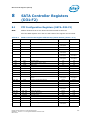
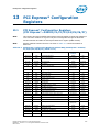
LPC Interface Bridge Registers (D31:F0)
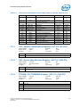
7.2.1
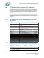
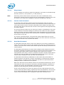
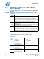
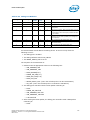
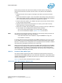
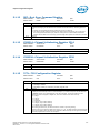
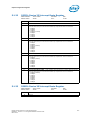
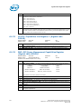
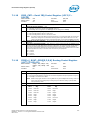
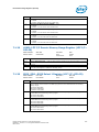
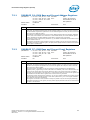
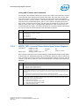
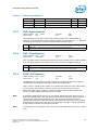
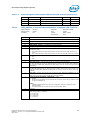
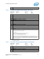
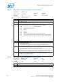
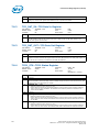
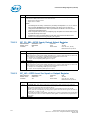
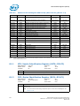
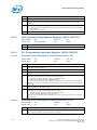
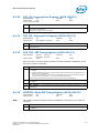
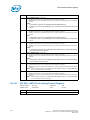
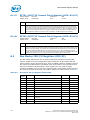
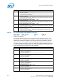
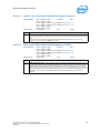
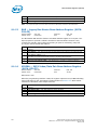
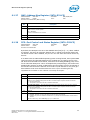
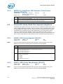
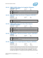
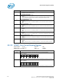
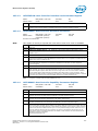
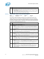
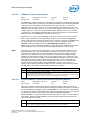
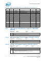
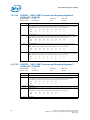
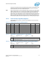
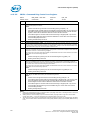
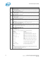
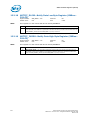
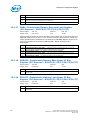
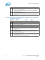
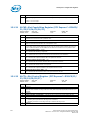
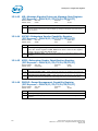
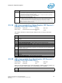
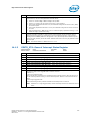
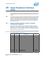
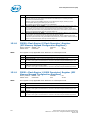
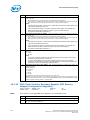
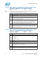
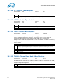
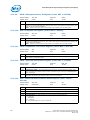
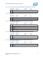
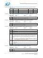
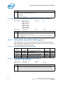
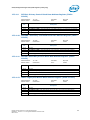
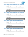
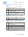
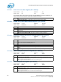
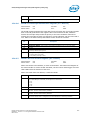
DMABASE_CA—DMA Base and Current Address Registers
I/O Address:
Default Value:
Lockable:
7.2.2
Ch. #0 = 00h; Ch. #1 = 02h
Ch. #2 = 04h; Ch. #3 = 06h
Ch. #5 = C4h Ch. #6 = C8h
Ch. #7 = CCh;
Undefined
No
Attribute:
Size:
R/W
16 bits (per channel),
but accessed in two 8
bits quantities
Power Well:
Core
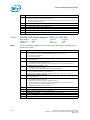
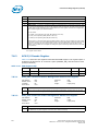
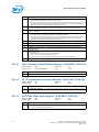
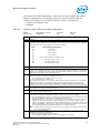
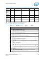
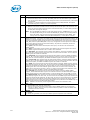
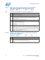
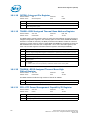
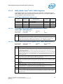
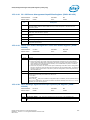
Bit
Description
15:0
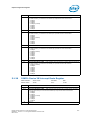
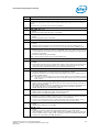
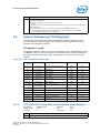
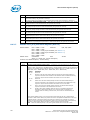
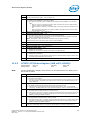
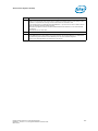
Base and Current Address — R/W. This register determines the address for the transfers to be
performed. The address specified points to two separate registers. On writes, the value is stored in
the Base Address register and copied to the Current Address register. On reads, the value is returned
from the Current Address register.
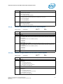
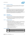
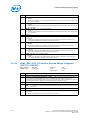
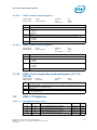
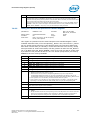
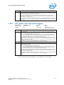
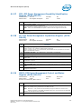
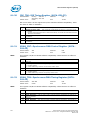
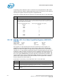
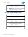
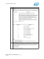
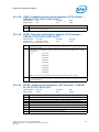
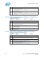
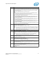
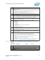
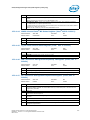
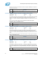
The address increments/decrements in the Current Address register after each transfer, depending
on the mode of the transfer. If the channel is in auto-initialize mode, the Current Address register
will be reloaded from the Base Address register after a terminal count is generated.
For transfers to/from a 16-bit slave (channels 5–7), the address is shifted left one bit location. Bit 15
will be shifted into Bit 16.
The register is accessed in 8 bit quantities. The byte is pointed to by the current byte pointer flip/
flop. Before accessing an address register, the byte pointer flip/flop should be cleared to ensure that
the low byte is accessed first.
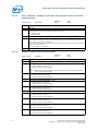
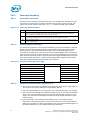
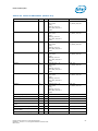
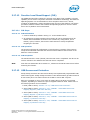
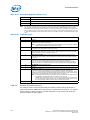
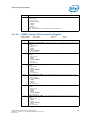
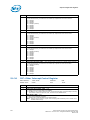
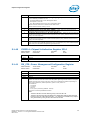
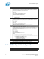
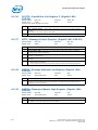
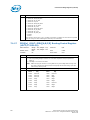
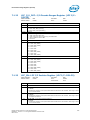
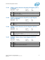
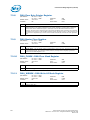
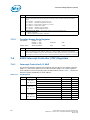
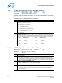
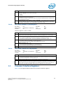
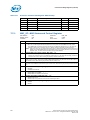
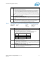
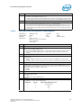
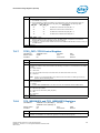
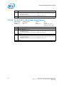
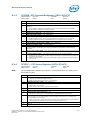
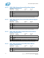
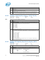
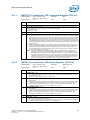
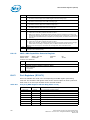
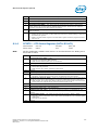
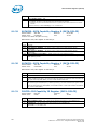
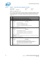
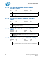
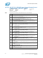
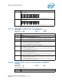
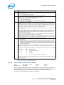
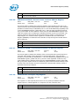
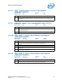
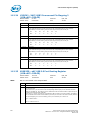
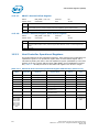
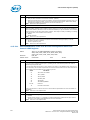
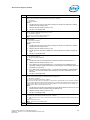
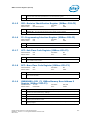
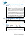
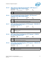
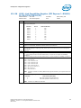
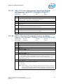
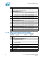
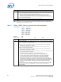
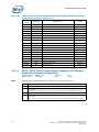
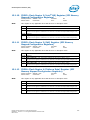
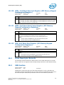
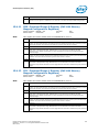
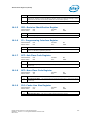
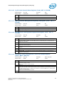
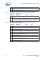
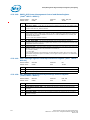
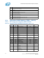
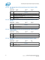
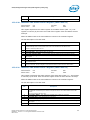
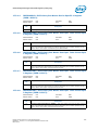
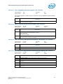
DMABASE_CC—DMA Base and Current Count Registers
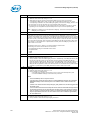
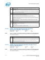
I/O Address:
Default Value:
Lockable:
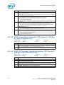
Ch. #0 = 01h; Ch. #1 = 03h Attribute:
Ch. #2 = 05h; Ch. #3 = 07h Size:
Ch. #5 = C6h; Ch. #6 = CAh
Ch. #7 = CEh;
Undefined
No
Power Well:
R/W
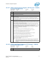
16 bits (per channel),
but accessed in two 8
bits quantities
Core
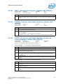
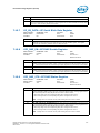
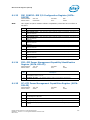
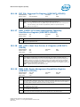
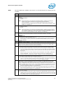
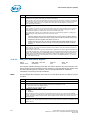
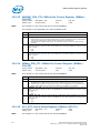
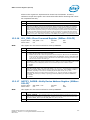
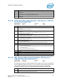
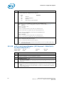
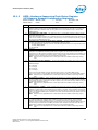
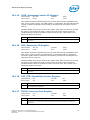
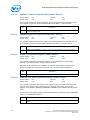
Bit
Description
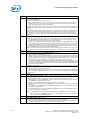
15:0
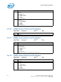
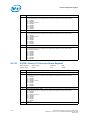
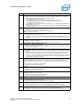
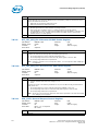
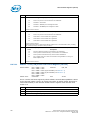
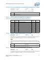
Base and Current Count — R/W. This register determines the number of transfers to be
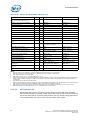
performed. The address specified points to two separate registers. On writes, the value is stored in
the Base Count register and copied to the Current Count register. On reads, the value is returned
from the Current Count register.
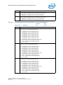
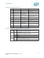
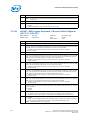
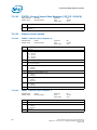
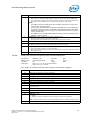
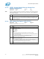
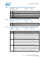
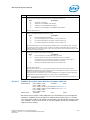
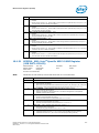
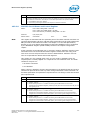
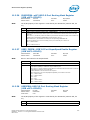
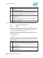
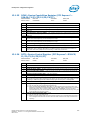
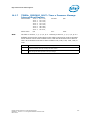
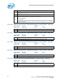
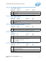
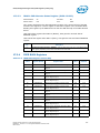
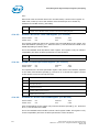
The actual number of transfers is one more than the number programmed in the Base Count
Register (that is, programming a count of 4h results in 5 transfers). The count is decrements in the
Current Count register after each transfer. When the value in the register rolls from 0 to FFFFh, a
terminal count is generated. If the channel is in auto-initialize mode, the Current Count register will
be reloaded from the Base Count register after a terminal count is generated.
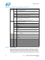
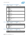
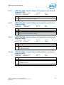
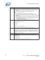
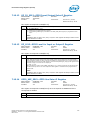
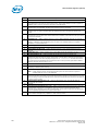
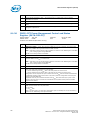
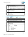
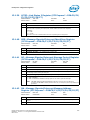
For transfers to/from an 8-bit slave (channels 0–3), the count register indicates the number of bytes
to be transferred. For transfers to/from a 16-bit slave (channels 5–7), the count register indicates
the number of words to be transferred.
The register is accessed in 8 bit quantities. The byte is pointed to by the current byte pointer flip/
flop. Before accessing a count register, the byte pointer flip/flop should be cleared to ensure that the
low byte is accessed first.
Intel® Xeon® Processor D-1500 Product Family
Datasheet - Volume 1 of 4: Integrated Platform Controller Hub
March 2015
261