1
Orion ISS
S2000/S2000M Console Programming Tool
PPROG
User’s Manual
This Manual describes the setup, interface, and operation of PProg software of version 3.00 which is
intended for security managers to program S2000/S2000M fire and alarm consoles.
Please read all the instructions completely before programming the S2000/S2000M console
and save this Manual for further references
The terms below are used throughout this manual:
Alarm Loop (or Loop, or LP): The “alarm loop” is the same as the “initiating device circuit”, that is,
an electrical circuit connected to a monitored input of an Orion system device, this circuit some
conventional fire or intrusion detectors being brought in. A response of any single detector
brought into the alarm loop causes the entire loop to response, so, the accurate location of the
detector within the loop can not be known
Arm / Disarm: This means starting/cancelling monitoring for zone conditions and sending alarms
when the condition are changed
Authenticator: A means for users to be authenticated by the system to gain access to various system functions such as configuring, arming, disarming, releasing extinguishing agent, and so
on. The console supports operating with such authenticators as PIN-codes entered from the
console or keypads and various access devices presented to the system readers including
iButtons and Proximity cards
Centralized Relay Control: The control method when the console gathers the device status data,
analyses them, and gives commands to activate system executive devices depending on the
logic programmed in the console database. In such a case the zones monitored by the console and the executive outputs controlled by this one can be parts of different devices
Local Relay Control: The control method when a device monitors statuses of its own input zones,
analyses these data, and activates its own relay outputs depending on the local logic programmed in its configuration
Network Address: A unique number ranged from 1 to 127 of the device within the Orion ISS local
RS-485 network
Partition: A set of zones that are controlled as a whole. As a rule, zones fall into partitions depending
on their location (e.g., a partition can involves all zones on an individual area)
Zone: A minimal physical part or behavior aspect of a device in a security and safety installation that
can be monitored and controlled independently. Depending on the context, the term “zone”
can mean an alarm loop, an addressable detector in an S2000-KDL polling loop, a device circuit of an addressable input module, a reader input, a device input, status of the device itself,
and so on
PProg
Table of Contents
GENERAL ............................................................................................................................... 7
PPROG INTERFACE .............................................................................................................. 9
PProg Menu................................................................................................................................ 11
File..................................................................................................................................... 11
Edit .................................................................................................................................... 11
S2000 ................................................................................................................................ 12
Options .............................................................................................................................. 12
Language .......................................................................................................................... 13
Service .............................................................................................................................. 13
Pages ................................................................................................................................ 13
Help ................................................................................................................................... 14
Quick Access Toolbar................................................................................................................. 14
Page Icon Toolbar ...................................................................................................................... 15
Information Panel........................................................................................................................ 16
Recycle Bin ....................................................................................................................... 16
Console Status Indicator ................................................................................................... 17
Console Version Indicator ................................................................................................. 17
Scenario Memory Indicator ............................................................................................... 17
Program Settings ........................................................................................................................ 18
Program Window View Settings ........................................................................................ 18
Program Operation Settings .............................................................................................. 20
Setting Writing Parameters ............................................................................................... 22
Setting Port Parameters .................................................................................................... 24
PPROG OPERATING............................................................................................................ 25
Connecting and Preparing the Console...................................................................................... 26
Opening Console Configuration.................................................................................................. 28
Creating a New Configuration ........................................................................................... 28
Loading Configuration from a File ..................................................................................... 29
Loading a Configuration from the Console Memory .......................................................... 30
Completing the Work .................................................................................................................. 31
Writing the Configuration to the Console Memory............................................................. 31
Writing the Configuration to a File ..................................................................................... 33
DEVICE TYPES..................................................................................................................... 35
Reviewing Parameters of Programmed Custom Device Types.................................................. 37
Programming a New Custom Device Type................................................................................. 38
Defining Device Types Based on the Standard Template................................................. 40
Defining Device Types Based on the S2000-KDL Template............................................. 41
Defining Device Types Based on the S2000-ASPT Template .......................................... 43
Editing Parameters of Custom Device Types ............................................................................. 44
Deleting a Custom Device Type ................................................................................................. 45
3
www.bolid.com
Orion ISS
DEVICES ............................................................................................................................... 47
Adding a Device Descriptor to the Console Database ................................................................49
Finding and Polling Connected Devices ............................................................................49
Manual Adding Device Descriptors to the Console Database ...........................................50
Changing Device Descriptors......................................................................................................51
Deleting Device Descriptors ........................................................................................................52
PARTITIONS ......................................................................................................................... 55
Creating a Partition Descriptor ....................................................................................................58
Defining / Editing Zone Parameters ............................................................................................58
Including Zones into Partitions ....................................................................................................60
Editing a Partition ........................................................................................................................61
Deleting a Partition ......................................................................................................................61
Redefine an Addressable Input of an S2000-KDL as an Output.................................................62
Sorting Partitions .........................................................................................................................63
GROUPS OF PARTITIONS................................................................................................... 65
Creating a New Partition Group ..................................................................................................67
Editing / Deleting a Descriptor of a Partition Group.....................................................................68
RELAYS ................................................................................................................................ 69
The Page for Relays Grouped by Devices ..................................................................................71
The Page for Relays Grouped by Partitions................................................................................72
Creating an Algorithm for Centralized Control for the Relay .......................................................73
Assigning System Partitions to the Controlled Relay .........................................................73
Setting the Relay Control Parameters................................................................................74
Editing / Deleting a Centralized Control Algorithm ......................................................................75
Redefine an Addressable Output of an S2000-KDL as the Input................................................76
ACCESS GROUPS ............................................................................................................... 77
The Page for Partitions Grouped by Access Groups ..................................................................79
The Page for Access Groups Grouped by Partitions ..................................................................81
Creating a New Access Group to Control Partitions ...................................................................82
Adding the Descriptor of an Access Group to Control Partitions .......................................82
Assigning the Access Group Descriptor with System Partitions ........................................83
Selecting User Authorities to Control Partitions .................................................................83
Editing Access Group Parameters ..............................................................................................84
Deleting an Access Group...........................................................................................................85
AUTHENTICATORS.............................................................................................................. 87
Creating / Enrolling an Authenticator...........................................................................................90
Adding an Authenticator Code Manually............................................................................90
Enrolling a Password or Key by One of the Orion System Devices...................................90
Importing Key Descriptors from a File................................................................................91
Defining / Changing Parameters of Authenticators ............................................................92
Editing / Deleting an Authenticator ..............................................................................................93
www.bolid.com
4
PProg
EVENT TRANSLATION ........................................................................................................ 95
Defining an Event Translation Rule ............................................................................................ 98
Selecting the Device Events Will Be Translated To .......................................................... 99
Defining the List of Partitions Which Statuses Will Be Translated................................... 100
Defining the Event Category ........................................................................................... 100
Editing an Event Translation Rule ............................................................................................ 102
Deleting an Event Translation Rule .......................................................................................... 103
ENTRANCE ZONES ........................................................................................................... 105
Creating Entrance Zones.......................................................................................................... 108
Changing Parameters of Entrance Zones ................................................................................ 109
Delete an Entrance Zone.......................................................................................................... 110
DEVICE RIGHTS................................................................................................................. 111
Defining Rules for Devices to Control Partitions....................................................................... 114
Permitting Controlling Partitions from the Console, a Keypad, or a Reader.................... 114
The Combined Association to Control Partitions Remotely............................................. 114
Editing / Deleting Device Rights ............................................................................................... 115
CUSTOM EVENTS .............................................................................................................. 117
Creating an Event Processing Scenario ................................................................................... 120
Defining the List of Custom Events ................................................................................. 120
Assigning the Event Processing Scenario to a Zone / Zones.......................................... 122
Editing a Scenario or a Scenario-to-Zone Link ......................................................................... 123
Deleting a Scenario / Event ...................................................................................................... 123
MANAGEMENT SCENARIOS ............................................................................................ 125
Creating Management Scenarios ............................................................................................. 130
Creating a Voice Notification Scenario ............................................................................ 131
Creating a Relay Control Scenario .................................................................................. 133
Creating an Access Control Scenario.............................................................................. 137
Creating Management Scenarios to Control a Zone / Loop ............................................ 139
Defining Conditions to Manage Partitions for Scenario Components.............................. 142
Editing Parameters of Management Scenarios ........................................................................ 144
Deleting a Management Scenario or a Scenario-to-Zone Link................................................. 144
Storing Management Scenarios in the Console Memory ......................................................... 144
5
www.bolid.com
PProg
General
GENERAL
The PProg Programming Tool is designed to program following fire and alarm consoles of the Orion
system:
S2000 of versions 1.10 to 1.24 and
S2000М of versions 2.01 to 2.05.
The PProg is installed on a computer which is connected to the console via its RS-232 or USB port
and operates under Windows 2000, Windows XP, Windows 2003 Server, and Windows Vista.
The PProg is designed to program a database for the console used to control centrally all the cooperating Orion system devices. The database is to contain the descriptors of devices and their input and
output zones as well as define the logical algorithms of device cooperating. The console monitors
status of enrolled devices, activates outputs of enrolled devices, indicates system conditions on indicator modules, receives user commands given from keypads or readers connected to devices, translate system messages out of the Orion system, etc. To give detailed information about console operating, please refer to the Manual of the console being in use.
The PProg provides:
9
Reading the current configuration from the memory of the console or from a special file or creating a new configuration
9
Loading the configuration to the console memory or saving it as a text file, encrypted file or memory dump
9
Editing the configuration loaded to the PProg in order to:
–
Enroll in the console database the descriptor of the devices cooperating in the system under console controlling; the devices can be of one of standard or some custom user types
–
Combine input zones of various system devices into so called partitions to control them as
a whole
–
Establish logical links for centralized controlling system executive devices automatically
depending on statuses of monitored partitions
–
Enroll user authenticators such as PIN codes, iButtons, and Proximity cards and define
rules for their holders to gain access to system operations including configuring all the
system, arming and disarming system partitions and individual zones, releasing/aborting
extinguishing agent, enabling/disabling automatic release mode, etc.
7
www.bolid.com
Orion ISS
–
Adjust translating system events to remote indication devices and sending them out of the
system via various communication channels
–
Define entrance zones
–
Give custom responses for system events
–
Create complex flexible management scenarios to activate system executive devices
You can download the last version of the PProg from the web-site of the Bolid Company at the address of www.bolid.com
www.bolid.com
8
PProg
PProg Interface
PPROG INTERFACE
This chapter discusses the process of installing the PProg on the computer and user interface with
the PProg, namely:
¾
Program window
¾
Menu commands
¾
Program settings
¾
PProg toolbars
¾
PProg Information Panel
The PProg is to be installed on a personal computer (PC) operating under the following operating
systems:
9 Windows 2000
9 Windows XP
9
Windows 2003 Server
9
Windows Vista
To install the program, copy the program distributive to the required computer directory. If the distributive is a setup file, run it and follow Setup Master’s instructions; if, otherwise, you have an archive file,
unpack it and run the PProg.exe executive file.
9
www.bolid.com
Orion ISS
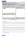
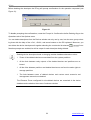
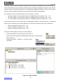
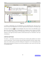
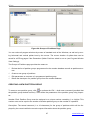
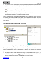
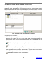
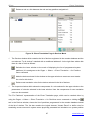
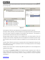
Following is the layout of the main PProg window (see Figure 1):
1
2
3
4
5
6
8
7
Figure 1. The PProg Layout
1. The PProg Menu
2. The Quick Access Toolbar; its tools can be signed or unsigned depending on the current setting of
the Show Menu Icon Names switch – see the Program Window View Settings section of this Manual
3. The Bolid Logo Button providing running the current web-browser and opening the site of the Bolid Company
4. The Page Icon Toolbar; this toolbar can be hided or shown depending on the current setting of the
Show Page Icons options –– see the Program Window View Settings section of this Manual
5. The current page of the PProg which can contain one or two windows depending on the page
content. The PProg having just been opened, always the Devices page (see the Devices section
is current
6. The Inspector which displays values of the parameters of an item selected in the current window
on the current PProg page
www.bolid.com
10
PProg
PProg Interface
7. The Status Bar to show current date and time, information about a current connected console,
and hints about purpose of the selected tools / actions / pages
8. The PProg Information Panel which displays the status of the connected console, the current version of the console / configuration, and availability of the console memory to be occupied by new
management scenarios. Also in the Information Panel there is the Recycle Bin, the graphic control
element to facilitate deleting database elements and links between them
View and size of the PProg window as well as size of pages window can be adjusted as suitable. The
PProg window can be resized by means of standard Windows tools. Internal layout and size of page
windows can be changed by dragging the vertical and horizontal splitter bars.
PPROG MENU
The PProg menu provides users with the access to program operations and settings, including the
following command units:
File
The File submenu involves the commands to operate with the console configuration and exit the
PProg:
New
To create new console configuration;
the newly created configuration can then be loaded to the console memory, or written
to a file, or used as a template to facilitate programming other consoles and so on
Open
To read a file with a console configuration and load the configuration to the PProg.
The configuration can be read from a file which was previously created by this or similar PProg program. The file can be either text file with the txt extension, or encrypted
file with the gpc or cpc extension, or memory dump with the dmp extension
Save
To write the configuration to a file
Save as
To write the configuration to the specified file
Exit
To exit the program
Edit
The submenu of this command involves the commands to edit selected program objects. The result of
edit commands depends on the current page and the selected object of the PProg. At each page of
the PProg edit commands are duplicated by some tools of the local page/window toolbars.
Add
The command to add a new object
Change
The command to change the parameters of the selected object
11
www.bolid.com
Orion ISS
Delete
The command to delete the selected object
Import Keys
The command to import authenticator codes from a file with ki extension (only for Authenticators page of the PProg).
S2000
The command submenu contains the commands to operate with the console memory:
Read Configuration
This command reads configuration of the connected and polled console from the console memory
and loads the read configuration to the PProg (see the Loading a Configuration from the Console
Memory section of this Manual)
Write Configuration
This command writes the programmed configuration from the PProg to the memory of the console
which is connected to a PC serial port and polled by the PProg (see the Writing the Configuration to
the Console Memory section of this Manual).
Options
The submenu of this command contains the titles of the tabs to adjust various options of the PProg as
well as two commands to adjust a view of the working window. Each command will be described in
details further in Section Program Settings of this Manual
Operations
Here are commands that define options for implementing some program operations of dialogue between a user and the program (see Program Operation Settings)
View
Here are commands to adjust the PProg window (see Program Window View Settings)
Console
Here are commands to adjust options for writing a configuration created by the PProg to the console
memory (see Setting Writing Parameters)
Serial Port
Here are commands to set parameters of a PC serial port of the computer the S2000/S2000M console is connected to (see Setting Port Parameters)
Show Menu Icon Names
This command displays/hides the descriptions of the graphic tools in the Quick Access Toolbar (see
Quick Access Toolbar)
Show Page Icons
This command displays/hides the Page Icon Toolbar (see Page Icon Toolbar)
www.bolid.com
12
PProg
PProg Interface
Language
This command enables choosing a language of the PProg interface. This version of the PProg supports two interface languages, namely Russian and English. To change the current language select
the new language in the Language menu and after confirming the operation the PProg will be rebooted with the selected interface language.
Service
Sort Partitions
This command enables reordering the list of system partitions (see the Partitions chapter of this Manual) in the internal representation of the console. If the sort operation has been implemented before
writing a configuration to the console memory, then a user while scrolling the list of the partitions forward will see on the console display the partitions in increasing order of indices.
Pages
This submenu involves a list of the commands to open PProg pages, where various console database
components can be programmed:
Device Types
The command opens the Device Types page of the PProg (see Device Types) similarly to the
Devices
tool on the Page Icon Toolbar
The command opens the Device page of the PProg which is by default opened
when the PProg has just been started (see Devices), similarly to the
tool on the
Page Icon Toolbar
Partitions
The command has two options and opens either the Partitions (see Partitions) or
Groups of Partitions (see Groups of Partitions) page of the PProg similarly to
or
tool on the Page Icon Toolbar respectively
Relays
The command opens the Relays page of the PProg (see Relays) similarly to the
tool on the Page Icon Toolbar. The command has two options representing links between relays and partitions grouped either by devices or partitions
Access Groups The command opens the Access Groups page of the PProg (see Access Groups)
similarly to the
tool on the Page Icon Toolbar. This command has two options
representing links between access groups and relevant partitions enabled to monitor
and control grouped either by partitions of access groups
Authenticators
The command opens the Authenticators page of the PProg (see Authenticators)
similarly to the
tool on the Page Icon Toolbar
13
www.bolid.com
Orion ISS
Others
Event Translation
The command opens the Event Translation page of the PProg (see Event Trans-
lation) similarly to the
tool on the Page Icon Toolbar. The command has two op-
tions representing translation rules either for devices or for partitions
Entrance Zones The command opens the Entrance Zones page of the PProg (see Entrance Zones)
similarly to the
Device Rights
The command opens the Device Rights page of the PProg (see Device Rights) similarly to the
Custom Events
tool on the Page Icon Toolbar
tool on the Page Icon Toolbar
The command opens the Custom Events page of the PProg (see Custom
Events) similarly to the
Management Scenarios
tool on the Page Icon Toolbar
The command opens the Management Scenarios page of the PProg (see
Management Scenarios) similarly to the
tool on the Page Icon Toolbar
Help
This command calls the PProg.hlp help file and gives brief information about the PProg program being in use:
Content
About PProg
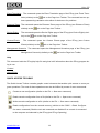
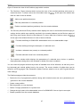
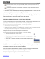
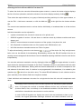
QUICK ACCESS TOOLBAR
The Quick Access Toolbar contains graphic control elements that enable quick access to some program operations. The most of these operations can also be fulfilled by means of menu commands:
Creates a new configuration (similar to the File → New menu command)
Reads console configuration from a file (similar to the File → Open menu command)
Writes console configuration to a file (similar to the File → Save menu command)
Reads configuration from the console memory (similar to the S2000 → Read Configuration menu command). Both the tool and command are disabled if no console is connected
to the computer and selected by the PProg (see PProg Operating)
www.bolid.com
14
PProg
PProg Interface
Writes configuration to the console memory (similar to the S2000 → Write Configuration
menu command). Both the tool and command are disabled if no console is connected to
the computer and selected by the PProg (see PProg Operating)
Opens the program page which precedes the current page
Opens the program page which follows the current page
The tools of this Toolbar can be signed depending on the current setting of the Show Menu Icon
Names switch in the Options menu (see Figure 5). If the switch is set on, the text under each icon
specifies the destination of this tool (see Figure 2).
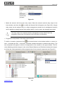
Figure 2. Quick Access Toolbar
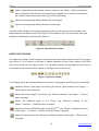
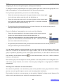
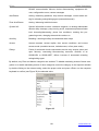
PAGE ICON TOOLBAR
The Page Icon Toolbar contains graphic control elements that enable opening various PProg pages
(see Figure 3). This Toolbar can be seen or hidden depending on the current setting of the Show
Page Icons switch from the Options menu. You can switch between PProg pages also by means of
arrow buttons on the Quick Access Toolbar or via Pages menu of the PProg.
Figure 3. Page Icon Toolbar
The following shows the matching between icon actions, PProg pages, and PProg menu commands.
Opens the Device Types page of the PProg (see Device Types) similarly to the Pages →
Device Types menu command
Opens the Devices page of the PProg (see Devices) similarly to the Pages → Devices
menu command
Opens
the
Partitions
page
of
the
PProg
(see
Partitions)
similarly
to
the
Pages → Partitions → Partitions menu command
Opens the Groups of Partitions page of the PProg(2.01+) (see Groups of Partitions) similarly
to the Pages → Partitions → Groups of Partitions menu command
Opens the Relays page of the PProg (see Relays) similarly to the Pages → Relays menu
command
15
www.bolid.com
Orion ISS
Opens the Access Groups page of the PProg (see Access Groups) similarly to the
Pages → Access Groups menu command
Opens the Authenticators page of the PProg (see Authenticators) similarly to the Pages
→ Authenticators menu command
Opens the Event Translation page of the PProg (see Event Translation) similarly to the
Pages → Others → Event Translation menu command
Opens the Entrance Zones page of the PProg (see Entrance Zones) similarly to the
Pages → Others → Entrance Zones menu command
Opens the Devices Rights page of the PProg(1.20+) (see Device Rights) similarly to the
Pages → Others → Device Rights menu command
Opens the Custom Events page of the PProg (2.01+) (see Custom Events) similarly to the
Pages → Others → Custom Events menu command
Opens the Management Scenarios page of the PProg (2.03+) (see Management Scenarios)
similarly to the Pages → Others → Management Scenarios menu command
NOTES:
(1.20+)
– This page is supported only for programming S2000 consoles of versions 1.20 and above,
(2.01+)
- This page is supported only for programming S2000M consoles of versions 2.01 and above,
(2.03+)
- This page is supported only for programming S2000M consoles of versions 2.03 and above.
All the PProg pages are discussed in details in the next chapters of this Manual.
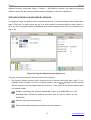
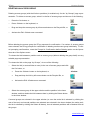
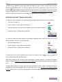
INFORMATION PANEL
The Information Panel of the PProg displays the Recycle Bin pictogram and a set of system indicators
namely Console Status Indicator, Console Version Indicator, and Scenario Memory Indicator (see
Figure 4).
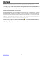
Figure 4. The Information Panel
Recycle Bin
The Recycle Bin is a graphic element which facilitates delete operations for users. To delete a database element or link between two elements just drag and drop it on the Recycle Bin pictogram. This
will be explained more thoroughly in further sections of this Manual.
www.bolid.com
16
PProg
PProg Interface
Console Status Indicator
The Console Status Indicator shows a current status of communications between the programmed
console and the PProg. It can be viewed as:
No console is connected to the PC or selected by the PProg
The console is selected, with no data being communicated between the console and the
PProg
The PProg is reading configuration from the memory of the selected console
The PProg is writing configuration into the memory of the selected console
Communications between the selected console and the PC has been lost
The Console Status Indicator will be discussed relative to PProg operations in the PProg Operating
section of this Manual.
Console Version Indicator
This indicator can display either the version of a console connected to the PC and selected by the
PProg or the version of a configuration created in the PProg and can be viewed as:
No configuration is loaded to the PProg (neither read from the console memory, nor loaded from a file, nor created in the current PProg session)
A new configuration is created by the PProg, with no console being connected to the PC
A console is connected to the PC and selected by the PProg, with the version of the console matching the version of the configuration created by the PProg
A console is connected to the PC and selected by the PProg, but the version of the console doesn't match the version of the configuration created by the PProg
The view of the pictogram depends on the sort of ongoing operation and its results and will be discussed further in this Manual.
Scenario Memory Indicator
Management scenarios (see Management Scenarios) are used to describe complex automatic management tactics for a system which is operated by the S2000/S2000M console depending on the
statuses of the system partitions (see Partitions). Management scenarios occupy some dedicated
console memory area, and the size of this memory cannot be exceeded.
17
www.bolid.com
Orion ISS
The Scenario Memory Indicator on the Information Panel indicates how much memory has
already been occupied by programmed scenarios in the current console configuration.
The currently occupied memory can be displayed either in bytes or as the percentage of
the maximum available value depending on the status of the Show the Memory Size of
Management Scenarios in Bytes switch on the View tab in Options menu (see Figure 5).
As soon as the current memory size of programmed management scenarios begins to
exceed the threshold value provided that the Check the Memory Size Occupied by Management Scenarios flag on the Operations tab of the Options menu is set off, the value of
the occupied memory size will be indicated with red. The configuration being written to the
console memory, a part of the configuration will be lost.
If the Check the Memory Size Occupied by Management Scenarios is on, the PProg monitors the
memory size of scenarios, while being programmed, and when this size is close to the maximum
value, programming of new scenarios or new components of scenarios becomes unavailable.
PROGRAM SETTINGS
Program Window View Settings
The PProg provides user with a number of means to adjust its work window in accordance with user's
wishes. By means of standard Window tools and special PProg tools you can expand the program
window to a comfortable size, move the window on the screen, resize the window, or change the window layout. You can also change the view of the Quick Access Toolbar showing or hiding textual descriptions for its tools. Moreover, you can show/hide the Page Icon Toolbar.
If you wish, you can change the color, type and size of fonts for titles and window content, change the
view of the Scenario Memory Indicator, and instruct the program to change the internal size for all the
page windows synchronously.
Adjusting the view of the PProg window is to be carried out by means of the View tab of the Options
menu (see Figure 5) and the two commands of the same menu (see Figure 6).
To change the font of window titles or text inside internal windows, set the proper values for the font
size in the Title Font Size or Text Font Size fields on the View tab. The font size can be varied in the
range of 8 to 12. Font of window titles or text can be made bold: for doing this set the relevant flag on.
www.bolid.com
18
PProg
PProg Interface
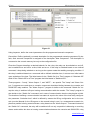
Figure 5. Options Window: View Tab
To change the color of window titles, window text, or selected text, open the dropdown list within the
Color Settings field and select the relevant string. Then open the Color Palette by left clicking on its
pictogram at the right border of the box. Select the proper color or define any other color as you wish.
The Remember Splitter Positions option provides remembering the internal configuration of the internal program windows for all program pages after single page window having been resized. It the option is set off, you can change the internal configuration of each page window independently.
The Show the Memory Size of Management Scenarios in Bytes option defines the view of the Scenario Memory Indicator (see Scenario Memory Indicator) in the Information Panel of the PProg. If this
flag is set on, the memory area occupied by programmed management scenarios is displayed in
bytes. Otherwise, if this flag is set off the occupied memory size is displayed as percentage of the
maximum value.
Figure 6. Options Menu
The Show Menu Icon Names switch defines the view of the tools of the Quick Access Toolbar (see
Figure 2). If this flag is set on, the tools are signed with its functional descriptions and arrow buttons
19
www.bolid.com
Orion ISS
are signed by titles of the previous and the next pages which can be open by means of button pressing.
The Show Page Icons switch controls the mode of displaying the Page Icon Toolbar in the main
PProg window (see Page Icon Toolbar). The Page Icon Toolbar to be seen, set this switch on, or,
otherwise, unset it if you want to hide this toolbar.
Program Operation Settings
The PProg provides adjusting some options of its dialog with user, namely:
9
The PProg can prompt user confirmation to delete some objects
9
The PProg can check the number of typed symbols when descriptions of some objects are entered by user
9
The PProg can check the memory size occupied by already programmed management scenarios
(see Management Scenarios)
9
The PProg can instruct the console to build the logic of automatic system control based on the
way partitions are combined to groups
These options are collected on the Operations tab of the Options menu (see Figure 7).
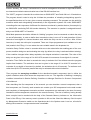
Figure 7. Options Window: Operations Tab
Prompt for Confirmation before Deleting
If this option is set on, then before deleting database components or logical links between the components, the PProg will prompt user to confirm the requested operation. You are advised to keep this
option turned on to avoid loss of data due to accidental delete. You can turn this option off for a time,
when necessary.
www.bolid.com
20
PProg
PProg Interface
Check the Length of Descriptions
The length of the descriptions of programmed database components which are to be stored in the
console memory and displayed by the console during operating (such as descriptions of partitions,
groups of partitions, relays, access groups, and authenticators) SHOULD NOT exceed 16 symbols. If
the descriptions are given with more than 16 symbols in the PProg, they can be stored in a configuration file but, when tried to be written to a console memory, the last symbols will be truncated.
If this switch is set on, the PProg will track the number of characters which are being entered for descriptions and block typing when 16 characters have been already entered.
Check the Memory Size Occupied by Management Scenarios
Management Scenarios (see Management Scenarios) describe a sophisticated logic of automatic
management of a system which operates under control of the console depending on the conditions of
system partitions (see Partitions). A special area in the console memory is designed to store programmed management scenarios.
The Scenario Memory Indicator on the Information Panel indicates how much memory has
already been occupied by programmed scenarios in the current console configuration. The
currently occupied memory can be displayed either in bytes or as the percentage of the
maximum available value depending on the status of the Show the Memory Size of Management Scenarios in Bytes switch on the View tab in Options menu (see Figure 5).
As soon as the current memory size of programmed management scenarios begins to
exceed the threshold value provided that the Check the Memory Size Occupied by Management Scenarios flag on the Operations tab of the Options menu is set off, the value of
the occupied memory size will be indicated with red. The configuration being written to the
console memory, a part of the configuration will be lost.
If the Check the Memory Size Occupied by Management Scenarios is on, the PProg monitors the
memory size of scenarios, while being programmed, and when this size is close to the maximum
value, programming of new scenarios or new components of scenarios becomes unavailable.
Take into Account the Groups of Partitions for Management Scenarios
Management Scenarios (see Management Scenarios) describe a sophisticated logic of automatic
management of a system which operates under control of the console depending on the conditions of
system partitions (see Partitions). If the list of the partitions which are involved to describe a system
condition is the same that the list of the partitions which are included to a partition group in the console database (see Groups of Partitions) then this list in the management scenario's memory can be
replaced by the descriptor of the partition group (if the option in question is set on). In such a case a
user will see program windows as before; however, the size of memory occupied by management
scenarios will be decreased
21
www.bolid.com
Orion ISS
Setting Writing Parameters
The PProg is equipped with a number of options for writing a created configuration to the console
memory. The most of these options regulates the memory size the console configuration will occupy
in the console non-volatile memory (if there is no enough free space in the console memory then
some options can be disabled).
These options are collected on the Console tab of the Options menu (see Figure 8).
Figure 8. Options Window: Console Tab
Write a Configuration to the Consoles with Compatible Versions
The PProg is intended to create configurations for all possible versions of S2000/S2000M consoles.
However, when the PProg are writing a created configuration to the console memory, the program
checks the version of the console which is connected to the PC at the moment. If the option in question is set off, only the configuration can be written to the console memory which version is strictly
equal to the version of the connected console. Otherwise, setting this option makes it possible to write
to the console the configuration of a compatible version.
The compatible configurations are these ones of versions 1.1x, 1.2x, and 2.0x. For each group of versions, younger versions of configuration are compatible with higher versions of consoles. For example, if the option is set on, the configuration of version 2.03 which is created or loaded to the PProg
operative memory can be written to the console of version 2.04 but cannot be written to the console of
version 2.02.
Data Block Length for Reading / Writing
This option provides defining the size of blocks of data returned by the console as a result of reading
or writing requests. Varying the block size can be necessary when there are some problems with
www.bolid.com
22
PProg
PProg Interface
reading data from or writing them to the console memory or when the communications between the
console and the PProg/PC are unstable.
Write the Descriptions of Vacant Zones
Zones of devices are considered to be vacant if they are not included to the logic partitions (see
Partitions) of the console database. By default the descriptors of such zones are not written to the
console database. However, if the option in question is set on the descriptions given for vacant zones
can be written to the console memory.
Write the Custom Events for Vacant Zones
Zones of devices are considered to be vacant if they are not included to the logic partitions (see
Partitions) of the console database. By default the descriptors of such zones are not written to the
console database. However, if the option in question is set on the custom scenarios of processing
events given for vacant zones can be written to the console memory.
Write the Numbers of ID-Contact Vacant Zones
Zones of devices are considered to be vacant if they are not included to the logic partitions (see
Partitions) of the console database. By default the descriptors of such zones are not written to the
console database. However, if the option in question is set on the ID Contact numbers given for vacant zones can be written to the console memory.
Write the Parameters of Vacant Relays
Relay outputs of devices are considered to be vacant if they are not used in the logic of centralized
system control, that are such relay outputs which are assigned neither to any partition condition (see
Relays) nor any management scenario (see Management Scenarios). Nevertheless, the parameters
of a vacant relay can be given on the Relays page of the PProg.
If this option is set off, the descriptors of vacant relays are not written into the console memory. If,
otherwise, the option is set on (and there is enough space in the console memory) the relay remote
control parameters (see Setting the Relay Control Parameters) are written to the console memory. If,
in addition, the Write the Descriptions of Device Types, Devices and Relays option (see below) is set
on, the description of vacant relays are written to the console memory too.
Write the Descriptions of Device Types, Devices and Relays
By default descriptions of device types, devices and relays are not written to the console memory
(however, they are still written to a configuration file if it is done). Setting this option on instructs the
PProg to write into the console memory the programmed descriptions of the device types, devices
and relays if there is enough console memory.
Relay descriptions (see Section Setting the Relay Control Parameters) will be written to the console
memory if only the relay is assigned to a partition/management scenario or the Write the Parameters
of Vacant Relays switch (see above) is set on.
23
www.bolid.com
Orion ISS
Setting Port Parameters
The Port tab of the Options menu (see Figure 9) involves options which regulate parameters of the
serial port through which the console communicates data with the PC in cases of finding devices as
well as reading console configuration from or writing it to the console memory.
Figure 9. Options Window: Port Tab
These options are to be varied when some problems with the communication line or communicating
data have been occurred. (For example, the PProg cannot find the console or the Console Status
Indicator shows failures, see PProg Operating).
The Number of Stop Bits parameter is advisable to be set to 2.
The Receive / Transmit Switching parameter defines the way of receiving/transmitting data at the port
(automatically or software supported) depending on the way the console is connected to the computer. If the console is connected:
9
To a RS232 port of the computer via the console's RS232 port, or
9
To a RS232 port of the computer via the console's RS485 port and an S2000-PI interface converter, or
9
To a USB port of the computer via the console's RS485 port and a relevant interface converter,
the "S2000/S2000-PI" value is recommended to be selected.
If, otherwise, the console is connected to a RS232 port of the computer via the console's RS485 port
and a PI-GR interface converter, the "PI/PI-GR" value should be set.
If the console is not recognized by the PProg during program operating, you can try to fix the problem
by selecting another value of the Receive / Transmit Switching parameter.
www.bolid.com
24
PProg
PProg Operating
PPROG OPERATING
This chapter discusses the general aspects of configuring an S2000/S2000M console by means of
the PProg such as:
¾
Preparing the console for configuring
¾
Creating a new configuration
¾
Loading a configuration from the console memory or from a special file
¾
Writing a configuration to the console memory or to a file
The issues dealing with editing a console configuration and creating a console database will be discussed in further chapters of this Manual.
To configure (or to program) an S2000/S2000 console, do the following (as will be discussed below):
)
Connect the RS-485 interface line, the console and other devices are connected to, to the computer and switch the console to the Programming Mode
)
Read the configuration from the console memory or, if the console is being programmed for the
first time or its current configuration can be ignored, load the configuration from a configuration
file or create a new configuration
)
Form the console database by setting or editing all the necessary parameters
)
Write the defined configuration to the console memory and, if necessary, save it to a file in order
to backup data, or to load the configuration to another console, or to be used as a template to
program another console etc.
25
www.bolid.com
Orion ISS
CONNECTING AND PREPARING THE CONSOLE
To prepare the console for reading configuration or writing configuration to it, the following is to be
done:
9 Connecting the console to any free serial port of the computer (either RS232 or USB) the PProg is
installed to
9 Turning the power of the console and the interface converter on
9 Assigning the console to a network address within the RS-485 interface line the console along
with other devices are connected to
9 Switching the console to the Programming Mode (the console LCD shall display "PROGRAMMING")
9 Finding and selecting the console by the PProg on the Devices page of the PProg
The console can be connected to the computer either via the console's RS-232 port (printer output)
by means of the special cord or via the console's RS-485 port using Bolid manufactured interface
converters S2000-PI, PI-GR, S2000-USB, USB-RS485. All the questions dealt with connecting the
console to the computer are detailed in the Manual for the console being in use. Be sure the serial
port of the computer the console is connected to is not busy by communicating data with another programs (such as the Bolid manufactured UProg, Orion KD Database Administrator, Orion KD Operative Task, Orion Pro Polling Kernel, Orion Control Module, S2000 System Software and so on).
To assign a network address and to switch the console to the Programming Mode, please refer to the
Manual for the console being in use.
To search the console by the PProg, open the Devices page. This page is opened once the PProg
has just be run, or, otherwise, can be reached by selecting the
by listing PProg pages with the help of the arrow buttons
and
icon on the Page Icon Toolbar, or
on the Quick Access Toolbar,
or by using the Pages → Devices menu command.
When the Devices page has been opened, specify in the Port field
of the Search window
the serial number of the computer’s port the console is connected to. Then press the Start Searching
button
. The PProg will poll all the devices which are currently connected to the specified port. As
the devices are being found they are added along with their types and version numbers to the list of
the found devices in the Search window.
Once the PProg has found a console connected to the serial port, the Console Status Indicator in the
Information Panel changes its view from
to
. Moving your mouse over the Console Status
Indicator causes the status bar to show the number of the COM-port the console is connected to, the
console address within the RS-485 interface line, and the version number of the console configurawww.bolid.com
26
PProg
PProg Operating
tion. All those mean that the console has been binded to the PProg and now is selected by the PProg.
Further, the PProg will operate this console even if another console has been found.
If you need to program another console (for example, a console connected to another COM port),
release the bind between the current console and the PProg by dragging and dropping the Console
Status Indicator
as
on the Recycle Bin
. Once the Console Status Indicator has been seen
, repeat finding connected devices from the beginning. If you need to select a console which
is shown in the Search window, just drag and drop the new console descriptor from the Search window on the Console Status Indicator.
If after completing a finding routine a console connected to the computer has not been found, do the
following:
9
Be sure the console is properly connected to the computer and turned on along with the interface
converter if used as well as the console is assigned to a unique RS-485 address and switched to
the Programming Mode
9
Be sure the parameters of the serial port (see the Setting Port Parameters section of this Manual)
are set properly: the Number of Stop Bits is equal to 2 while the "S2000/S2000-PI" value is selected (or the "PI/PI-GR" value, if the console is connected via a PI-GR interface converter) in the
Receive/Transmit Switching box , and finally
9
Search the console again
As far as a console has been found and selected by the PProg, the S2000 → Read Configuration
menu command and the
pictogram on the Quick Access Toolbar become available.
If a configuration is opened in the PProg when the console has been selected, also the S2000 →
Write Configuration menu command and the
pictogram on the Quick Access Toolbar become
available.
If the version of the configuration opened in the PProg doesn't comply with the
version of the console connected to the computer and selected as the current one,
then the Console Version Indicator on the Information Panel displays the
version number in red.
If the Write a Configuration to the Consoles with Compatible Versions switch is set
on, then a compatible (see Setting Writing Parameters) version of the configuration can be written to the connected and selected console. If, otherwise, this
switch is set off, the configuration CANNOT be written to the memory of a console
which version doesn't comply with the version of the current configuration
27
www.bolid.com
Orion ISS
OPENING CONSOLE CONFIGURATION
The PProg provides three ways to begin working with the console database:
9 To create a new configuration in the PProg
9 To load the configuration from a file where it was previously written by this or another PProg
9 To load to the PProg the current configuration of the console connected to the computer and
found by the PProg (if the console has ever been programmed and the current configuration is to
be saved)
Before the configuration opened in the PProg will be written to the console memory all data having already stored in the console memory are cleared
Creating a New Configuration
To create a new configuration (that is, a new console database), use the File → New menu command
or click the
pictogram on the Quick Access Toolbar. The PProg will prompt for the version number
of the console the configuration is to be created for (see Figure 10). Select the proper number and
click OK.
Figure 10
You are strongly advised to select the version which complies with the version of the programmed
console, or, otherwise, the configuration of a diverse version cannot be written to the console memory. You can also write the configuration of a compatible version (see Setting Writing Parameters) to
the console if the Write a Configuration to the Consoles with Compatible Versions parameter on the
Console tab from the Options menu (see Setting Writing Parameters) is set on.
As soon as the number of the configuration has been selected the PProg opens a new configuration
and all PProg pages available for the current version become enabled. The File → Save and
File → Save As menu commands and the
pictogram on the Quick Access Toolbar become active.
The Console Version Indicator on the Information Panel displays the number of the created configuration by one of the following ways:
www.bolid.com
28
PProg
PProg Operating
- in grey text if no console is connected to the computer, or
- in green text if the configuration version and the version of the connected console match
each other, or
- in red text if the configuration version and the version of the connected console are not equal
to each other.
To close loaded configuration, drag and drop the Console Version Indicator on
the Recycle Bin.
If no configuration is opened in the PProg, menu commands as well as writing tools
and page icons become unavailable and the Console Version Indicator is empty.
Loading Configuration from a File
To load a configuration to the PProg from a file, select the File → Open menu command or click the
pictogram on the Quick Access Toolbar. Then find and select the configuration file which you are
going to open in the appeared dialog window. The configuration file must be created by this or a similar PProg program and can be of one of the following types:
9 Text file with the txt extension in which a configuration is represented as a text containing parameters and their values
9 Encrypted file with the gpc or cpc extension where a console configuration is stored in encrypted
form
9 Console memory dump with the dmp extension where the memory dump of the console is written
If the valid file is selected, the PProg will open the configuration read from the file, and all the PProg
pages supported for the current configuration version will be available. Also the File → Save and
File → Save As menu commands and the
pictogram on the Quick Access Toolbar become active.
The Console Version Indicator on the Information Panel displays the number of the created configuration:
- in grey text if no console is connected to the computer,
- in green text if the configuration version and the version of the connected console match
each other,
- in red text if the configuration version and the version of the connected console are not equal
to each other.
To close loaded configuration, drag and drop the Console Version Indicator on
the Recycle Bin.
29
www.bolid.com
Orion ISS
If no configuration is opened in the PProg, menu commands as well as writing tools
and page icons become unavailable and the Console Version Indicator is empty.
Loading a Configuration from the Console Memory
To load the current console configuration from the console memory, be sure:
9 The console is properly connected to the computer
9 The console and the interface converter if used are turned on
9 The console is switched to the Programming Mode that is indicated by the "PROGRAMMING" text
string on the console LCD
9 The console is ready to communicate data with the PProg: the Console status Indicator on the
Information Panel is seen as
and moving the mouse over the Console Status Indicator
causes the status bar to show the number of the COM-port the console is connected to, the console address within the RS-485 interface line, and the version number of the console configuration
Otherwise, prepare the console as discussed in the Connecting and Preparing the Console chapter of
this Manual.
To load the console configuration from the console memory to the PProg, use the S2000 → Read
Configuration menu command or the
pictogram on the Quick Access Toolbar. While the configu-
ration is being read from the console memory, the PProg is displaying the process by the Progress
Indicator, the Console Status Indicator being looking as
.
Some failures can happen during reading configuration from the console memory, among them:
9 Loss of communications between the console and the PProg (for example, the console is
switched off from the Programming Mode while its configuration is still being read). In such case
pictogram. Check whether the console is
the Console Status Indicator is shown by the
properly connected to the computer, whether it is turned on (and the interface converter, if used, is
turned on too), and whether the console is switched to the Programming Mode.
9 Unstable communications between the console and the PProg. In such a case the Console Status
Indicator changes the view from
to
and back. Check and adjust if necessary the set-
tings of the port parameters (see the Setting Port Parameters section of this Manual)
If reading the configuration has been completed successfully, the configuration will be opened in the
PProg, with all page icons available for the current version of the console becoming enabled. Moreover, a number of writing commands of the program menu as well as the
www.bolid.com
30
and
pictograms on
PProg
PProg Operating
the Quick Access Toolbar are activated. The Information Panel displays the current version of the
read configuration (for example,
).
To close loaded configuration, drag and drop the Console Version Indicator on
the Recycle Bin.
If no configuration is opened in the PProg, menu commands as well as writing tools
and page icons become unavailable and the Console Version Indicator is empty.
All these actions will be implemented if the Cancel button is activated while the process of reading
console configuration has not been completed.
COMPLETING THE WORK
When programming the console has been completed, the configuration should be written to the console memory and (optionally) to a file for further usage.
Writing the Configuration to the Console Memory
Before the configuration opened in the PProg will be written to the console memory all data having already stored in the console memory are cleared
Before writing a configuration to the console memory, you are advised to reorder the list of system
partitions in the internal representation by using the Service → Sort Partitions menu command. In
such a case, a user while scrolling the list of the partitions forward will see the partitions on the console display in increasing order of indices.
Before writing the configuration, ensure that the S2000/S2000M console has been:
9 Connected to the computer and turned on (along with the interface converter, if applicable), and
9 Switched to the Programming Mode (you must see the text "PROGRAMMING" on the console
display), and
9 Selected as the configured device and ready to communicate data with the computer (which shall
be indicated by the Console Status Indicator in the Information Panel seen as
). Moving
your mouse over the Console Status Indicator should cause the status bar to show the COM-port
number the console is connected to, the console address within the RS-485 interface line, and the
version number of the console configuration.
Otherwise, prepare the console as discussed in the Connecting and Preparing the Console chapter of
this Manual.
31
www.bolid.com
Orion ISS
Moreover, you can write the configuration to the console memory if only the configuration has been
opened in the PProg, that is either has been preliminary loaded from the memory of this or another
console, or read from a file, or newly created by means of PProg tools. If so, the S2000 → Write Configuration menu command and the
pictogram on the Quick Access Toolbar are available to use.
The Console Version Indicator on the Information Panel shows whether or not the version of the
opened configuration complies with the version of the connected console. The configuration opened
in the PProg can be written to the console memory if the version of the opened (either newly created
or loaded by any way) configuration is identical to the version of the connected console. In such a
case the Console Version Indicator displays the version number in green:
.
If the version of the configuration opened in the PProg doesn't comply with the
version of the console connected to the computer and selected as the current one,
then the Console Version Indicator on the Information Panel displays the version
in red:
.
If the Write a Configuration to the Consoles with Compatible Versions switch is set
on, then a compatible version of the configuration (see Setting Writing Parameters) can be written to the connected and selected console. If, otherwise, this
switch is set off, the configuration CANNOT be written to the memory of a console
which version doesn't comply with the version of the current configuration
To write the current configuration from the PProg to the console memory, use the S2000 → Write
Configuration menu command or click the
pictogram on the Quick Access Toolbar. While the con-
figuration is being written the ongoing process is being indicated by the Progress Bar in the appeared
PProg window, the Console Status Indicator being seen as
. To cancel writing the configuration,
click Cancel in the Writing the Configuration to the Console window.
When the configuration is being written to the memory of an S2000 console, all those zone and output descriptors are saved which are defined in the database explicitly
When the configuration is being written to the memory of an S2000M console, by default only those device zones (alarm loops, addressable detectors,
monitored circuits, or monitored outputs) are saved which are assigned to console
partitions (see the Device Types section) as well as only those relay outputs are
www.bolid.com
32
PProg
PProg Operating
saved which are assigned to console partitions (see the Relays section of this
Manual)
PProg can also save the descriptors of the zones which are not assigned to any
partitions but are assigned with a textual description, or with an ID-Contact number, or with a defined custom event provided that the Write the Descriptions of
Vacant Zones, Write the Numbers of ID-Contact Vacant Zones, and Write the
Custom Events for Vacant Zones switches on the Console tab of the Options
menu are set on respectively
Failure to write a configuration to the console memory can be caused by one of the following:
9 Loss of the communication between the PProg and the console, for example, due to the console
being turned off or exiting the Programming Mode during writing. In such a case the Console
Status Indicator looks as
. If so, inspect whether the console is being connected to the com-
puter, and whether this one is being turned on (along with the interface converter, if used), and
whether it is keeping the Programming Mode.
9
Lack of the communication between the PProg and the console. In such a case the Console
Status Indicator looks as
and
alternately. If so, check and adjust, if necessary, set-
tings of the Port parameters see the Setting Port Parameters section of this Manual).
If Cancel is clicked or the console exits the Programming mode while the configuration is being written
to the console memory, the configuration saved in the console memory will be invalid and inoperable.
In such a case DO WRITE the configuration to the console memory REPEATEDLY.
Writing the Configuration to a File
You can write the console configuration to a file in order to:
9 Backup data
9 Load this configuration to another console connected to another computer
9 Use this configuration as a template to program other consoles
9 Send the vendor the configuration file in case of a program failure
All data typed on PProg pages are written to configuration files (on the contrary to data written to the
console memory, a part of which can be truncated - see the Program Settings section of this Manual).
The console configuration can be written in a number of formats:
9 To a text file with the txt extension, the configuration being written as a text including the names of
parameters and their values
33
www.bolid.com
Orion ISS
9 To an encrypted file with the gpc or cpc extension, the configuration being written in encrypted,
unreadable form
9 As a console memory dump with the dmp extension
The console configuration can be written to a file only if the configuration has been opened: either
loaded from the console memory, or loaded from a file, or created by the PProg in a current session.
In such a case the menu commands File → Save, File → Save As and the
pictogram on the
Quick Access Toolbar become enabled.
To save configuration to a file, select the File → Save menu command or use the
tool on the
Quick Access Toolbar. If the configuration is being written for the first time in the current PProg session, the PProg will prompt the path, name, and the type of the file the PProg must write configuration
to. For the next times, configuration is written to the file the name of which is displayed in the title of
the main PProg window. If you need to save the configuration under any other name, use the
File → Save As menu command.
www.bolid.com
34
PProg
Device Types
DEVICE TYPES
This chapter discusses the following questions:
¾
Standard and custom device types that can be used to describe devices in the console database
¾
When should you need to program a new custom device type in the console database
¾
Which pre-programmed templates are provided in the PProg to create custom device types
¾
How the program a new custom device type based on one of the pre-programmed templates
¾
How to edit / delete a custom device type
To work with device types the Device Types page of the PProg is designed.
The Device Type is the component of the console database which defines the handling logic of the
console with respect to a device as the system object. A device type, for example, describes how
many inputs and outputs the device has, if this one has monitored circuits or monitored outputs, which
monitored zones the device is equipped with, and so on.
The S2000/S2000M console database has a number of standard built-in device types to describe
various Orion system devices such as S2000-4, S2000-KDL, Signal-10, Signal-20P, etc.
Moreover, based on some various templates the PProg provides creating a number of new custom
device types. Programming custom device types is required in cases as follows:
1) To enroll the device that can not be described by any standard type of the current version of
the console
2) To decrease the number of input zones of a device which is to be enrolled in the console database (the total number of monitored zones in a console database cannot exceed a specified
35
www.bolid.com
Orion ISS
number, for example, 2048 for a console of versions 2.01 – 2.05). If a device can monitor a
large number of alarm loops, but actually only a part of them is in use, then it makes sense to
describe this device with the new custom type having less input zones. For example, if you enroll an S2000-KDL controller with its standard type, 127 zones will be reserved for this device
in the console database. If actually only 10 - 20 addressable devices are connected to the
controller, other reserved zones cannot be available and stand idle. If, otherwise, a new device
type is created for the controller (based on the S2000-KDL template, see below) which is designed for 20 input zones, only 20 zones will be occupied in the console database.
3) To describe an S2000-KDL some addressable zones of which are treated to be inputs, while
the others zones are treated as addressable executive outputs (to operate connected S2000SP2 relay modules)1.
4) To describe an S2000-ASPT panel which numbers of monitored circuits and executive outputs
depend on the number of connected S2000-KPB modules.
In all cases mentioned above a custom device type must be created and added to the console database to be assigned to specific devices.
The maximum number of custom device types which can be described for the console database is 16
for consoles of versions 1.1x and 30 for consoles of versions 1.2x and 2.0x.
Open the Device Types page by doing one of the following:
o
Click the Device Type icon on the Page Icon Toolbar, or
o
Find the page by browsing pages with the help of the arrow buttons on the
Quick access Toolbar, or
o
Activate the Pages → Device Types menu command
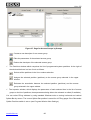
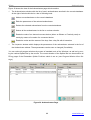
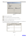
Figure 11 shows the view of the Device Types page which contains:
9 The Device Types window with the list of device types per-programmed (standard types) and already programmed (if presented) in the console database
9 A bar of tools which includes the New button
, the Edit button
, and the Cut button
9 The Inspector window which displays parameters of a selected device type
1
The consoles of late versions are equipped with more useful mechanism of subdividing S2000-KDL addressable zones when each addressable zone can be redefined either as an input or as an output – see Sections
Partitions and Relays.
www.bolid.com
36
PProg
Device Types
Figure 11
You can resize the window using standard Windows tools as well as by removing the vertical Splitter
Bar with the mouse. The current position of the Splitter bar can be saved for all PProg pages if the
Remember Splitter Positions switch is set on (see Program Window View Settings).
The Devices Types page provides the means to:
9
Review the list of standard and custom (if already programmed) device types in the console database
9
Program a new custom device type (if the total number of custom device types in the console
database doesn’t exceed the specified limitation – see above)
9
Edit parameters of a custom device type
9
Delete a custom device type from the console database
REVIEWING PARAMETERS OF PROGRAMMED CUSTOM DEVICE TYPES
To review parameters of a pre-programmed standard device type available for the console of the current version or parameters a custom device types programmed in the console database, select the
device type in the Device Types window. The parameters of the selected device type will be shown by
Inspector.
37
www.bolid.com
Orion ISS
PROGRAMMING A NEW CUSTOM DEVICE TYPE
A custom device type can be stored in the console database if there is at least a
device assigned to the custom device type (device types are assigned to devices
on the Devices page of the PProg, see Section Devices of this Manual)
To add a new custom device type to the console database, do one of the following:
o
Click the New button in the Device Types window, or
o
Press <Insert> on the keyboard (provided that a type or the root
element
are selected in the window), or
o
Activate the Edit → Add menu command
<Ins>
The maximum total number of custom device types in the console database is:
16 for S2000 consoles of versions 1.1x
30 for S2000 consoles of versions 1.2x and S2000-М consoles
If the number of custom types enrolled in the console database has already equal to the maximum
value (for current version of the console), the said tools to add custom types are unavailable.
After the new custom device type appearing in the list of types define its parameters in the Inspector
window.
You can give the new device type with a textual description. By default, all the added custom device
types are assigned to a name "New_#", where "#" is the sequential number of the device type for the
current session of the PProg. The type's description will be written to the console configuration and to
the console memory if a) there is at least a device in the console database which is assigned to this
type, and b) the Write the Descriptions of Device Types, Devices and Relays flag on the Console tab
of the Options menu is set on, and c) there is enough console memory.
The fundamental parameter of a custom device type is the Base Template. Each custom device type
can be described based on one of the three pre-programmed base templates which are the Standard
template, the S2000-KDL template, and S2000-ASPT template (only for consoles of versions 2.0x).
1.
Standard: Usually, this template is used for S2000 consoles of versions 1.10 - 1.24 to reduce the
total number of zones and outputs in the console database 2.
2
This mechanism is not up to date for S2000M consoles of versions 2.01 - 2.05. For an S2000M console, only
those zones and outputs are by default stored in the console database which are included to partitions (on the
www.bolid.com
38
PProg
Device Types
For example, let there are 30 Signal-20P devices which are connected to a S2000 console of version 1.24, with only 15 first alarm loops being actually used for each device (and five last alarm
loop being unused). However, 20 input zones will be occupied in the console database for each
device resulting in occupying 600 zones totally for these devices. But only 512 input zones can
be stored in the database of the console of version 1.24.
On the contrary, you can create a new device type based on the Standard template, the number
of alarm loops for this device type being 15. If such a new custom type will be assigned to all the
Signal-20P then the total number of input zones will be 30 × 15 = 450, so such a configuration
can be stored in the database of the S2000 console of version 1.24.
2.
S2000-KDL: This template is typically used for S2000 consoles of versions 1.10 - 1.24 in order to
reduce the number of S2000-KDL addressable zones in the console database as well as to describe an S2000-KDL which S2000-SP2 executive modules (operated by the console) are connected to3.
For example, let an S2000-KDL has a 20 actual zones and five addressable relay modules
(S2000-SP2s) are connected to this one (10 addressable relay outputs total). For consoles of
versions 2.01 - 2.05 you can just specify the addresses the relay modules are connected to. But
for the consoles of versions 1.10 - 1.24 you MUST CREATE a custom device type based on the
S2000-KDL template, the new type having 20 addressable zones and 10 addressable outputs.
3.
S2000-ASPT: This template is available only for consoles of versions 2.01 - 2.05 to describe
S2000-ASPT devices of versions 2.00 and above which some S2000-KPB executive modules
can be connected to, the modules being operated by the console. For example, let a system uses
one S2000-KPB module which is connected to an S2000-ASPT. If the console is supposed to
monitor S2000-KPB output conditions for open and short failures, it is necessary to create a new
device type based on the S2000-ASPT template with a slave module connected followed by including S2000-KPB’s outputs to a console monitored partition.
To define the base template for the created device type, select the type in the list and double click the
relevant entry in the Inspector window. Then select the proper template in the dropdown list confirming entering by pressing <Enter> on the PC keyboard (see Figure 12.
Partitions page - see Section Partitions) and assigned to partition statuses (on the Relays page – see Section
Relays) correspondently
3
Consoles S2000M of versions 2.01 – 2.05 provide a mechanism to define an addressable zone of an S2000KDL either as an input or an output (see Section Redefine an Addressable Input of an S2000-KDL as an Output). So, for these consoles, it is no needs to program a custom device type in using addressable relay modules
of S2000-KDL controllers.
39
www.bolid.com
Orion ISS
Figure 12
Then, depending on the specified device type template, define other specific parameters for the created device type.
Defining Device Types Based on the Standard Template
The Standard template provides defining a device with required numbers of zones and outputs (except for S2000-KDL and S2000-ASPT devices which custom types are to be described based on the
relevant templates - see below.)
Figure 13
Custom types based on the Standard template are given with two parameters (see Figure 13):
¾
The Number of Loops ranged from 0 to 127 and
¾
The Number of Relays ranged from 0 to 127
Use the Standard template to create custom types which are to be assigned to such devices as Signal-20, Signal-20 ser.02, Signal-20P, Signal-20M, S2000-2, S2000-4, S2000-SP1, and S2000-KPB.
These devices feature independent numerations for loops and relays, the numbers of both zones and
outputs starting with one.
For example, if a custom type based on the Standard template is enrolled with ten alarm loops and
three relay outputs, then the device of such type will have ten alarm loops with the numbers 1 to 10
and three relay outputs with the numbers 1 to 3.
www.bolid.com
40
PProg
Device Types
If you are going to use, for example, the loops from third to fifteenth for a device
of created type, DO NOT define for this type the Number of Loops as 13, otherwise the device will have the loops with numbers 1 to 13 and the working logic of
the device will mismatch description of this logic in the console database.
In such a case you must create a device type with 15 alarm loops. That is, give
device types with those Numbers of Loops which are equal to the last numbers of
the alarm loops that are actually used in the device.
This rule is true also for relay outputs
For example, let a system uses 30 devices Signal-20P connected to the console. Each device really
uses only the first 15 alarm loops, the last five alarm loops being unused. And each device really uses
only the first relay output to transmit fire alarms out of the system, last four outputs being unused or
controlled locally by the device itself. In such a case create a custom device type based on the Standard template and set its Number of Loops and Number of Relays parameters to the values of 15 and
1 respectively.
Defining Device Types Based on the S2000-KDL Template
Defining a custom device type based on the S2000-KDL template can be necessary in two cases:
9
You need to reduce the number of alarm loops intended in the database for each added S2000KDL (127 loops for each standard S2000-KDL) to match this number with the number of really
used alarm loops, or
9
You need to define a number of S2000-KDL addressable zones as inputs, the other zones being
treated as addressable outputs which S2000-SP2 addressable executive modules are to be connected to
In the last case, you can use (if available for the console of current version) more convenient mechanism for dividing addressable S2000-KDL zones onto inputs and outputs. S2000-KDL devices are
recommended to be added to the console database with their standard type, and then a part of
S2000-KDL zones can be redefined as outputs for that zones which the relay modules are really connected to (see Section Redefine an Addressable Input of an S2000-KDL as an Output).
You can redefine S2000-KDL inputs as addressable outputs only for those devices
which are assigned to a standard S2000-KDL type. For the devices assigned to a
custom S2000-KDL type redefining is disabled
Custom types based on the S2000-KDL template are given with two parameters (see Figure 14):
¾
The Number of Loops ranged from 1 to 127 and
¾
The Number of Relays ranged from 1 to 127
41
www.bolid.com
Orion ISS
Figure 14
The total number of loops and relays given for a custom S2000-KDL device type
MUST NOT exceed 127
If the limitation mentioned above is exceeded, the PProg outputs a warning (see Figure 15).
Figure 15
Note that the S2000-KDL template can be used ONLY to describe S2000-KDL devices. These devices use a single numeration both for addressable inputs and addressable outputs (if configured).
So, if you are going to use a custom S2000-KDL type, locate addressable inputs (designed for addressable detectors) at first polling loop addresses and addressable outputs (designed for addressable relay modules) at last polling loop addresses. If there is a custom S2000-KDL device type with
ten loops and six relays, a device of this type will have ten alarm loops with numbers 1 to 10 and six
relay outputs with numbers 11 to 16.
If a device really uses addressable zones with the addresses, for example, 3 to
10, you CANNOT specify for its custom type the Number of Loops equal to eight,
otherwise the addressable zones will be numbered from 1 to 8 and the real device
operating logic will mismatch the logic described for the device in the console. In
such case the device type MUST BE GIVEN with ten alarm loops.
That is, to describe a custom device type based on the S2000-KDL template, give
it with that Number of Loops which is equal to the address of the last zone really
used by the device (provided that all addresses of zones are less than addresses
of all addressable outputs). Subject to this provision, define the Number of Relays
equal to the address of the last used output minus the specified Number of Loops.
www.bolid.com
42
PProg
Device Types
For example, let we have an S2000-KDL which the addressable devices with the addresses of 3 - 10
and the relay modules with the addresses of 15 - 18 are connected to. In such case you should describe a custom device type based on the S2000-KDL template, having set 10 as the Number of
Loops and 8 as the Number of Relays respectively. A device of the described type will have ten alarm
loops with the numbers 1 to 10 and eight relay outputs with the numbers 11 to 18.
Defining Device Types Based on the S2000-ASPT Template
This template is used to describe S2000-ASPT devices of versions 2.00 and above, being available
only for S2000M consoles (of versions 2.01 - 2.05). It provides defining S2000-ASPT devices with
some connected S2000-KPB executive modules (up to 16 these executive modules can be connected
to each S2000-ASPT).
For a custom device type based on the S2000-ASPT template only a single parameter is to be defined. It is the number of slave S2000-KPBs ranged from 1 to 16 (see Figure 16).
Figure 16
Each S2000-KPB adds to the standard S2000-ASPT type three additional zones (two alarm loops of
the S2000-KPB and its tamper switch) and six monitored outputs (S2000-KPB circuits monitored by
the device itself for short/open failures).
The devices based on the S2000-ASPT template have a strictly defined numeration of alarm loops
and monitored outputs in the console database:
Zones 1…12:
Zones 20, 21, 22:
Zones 30, 31, 32:
monitoring alarm loops of the S2000-ASPT itself
("LP1", …, "Automatic Extinguishing System Trouble Monitoring")
monitoring the tamper switch and two alarm loops ("Pressure" and
"Mass") of the first S2000-KPB
monitoring the tamper switch and two alarm loops of the second S2000KPB
…
Zones 170, 171, 172: monitoring the tamper switch and two alarm loops of the 16th S2000KPB
&
Outputs 1…5:
monitoring the outputs of the S2000-ASPT itself
("EXIT", …, "Release Circuit")
Outputs 21…26:
monitoring the outputs of the first S2000-KPB
("Output 1", …, "Output 6")
Outputs 31…36:
monitoring the outputs of the second S2000-KPB
…
Outputs 171…176:
monitoring the outputs of the 16th S2000-KPB
43
www.bolid.com
Orion ISS
For example, if you have created the custom type based on the S2000-ASPT template with two connected S2000-KPBs, each device of this custom type will have 18 alarm loops and 17 monitored outputs:
Loops (Zones)
Monitored Outputs
1: Detection Loop 1 of the S2000-ASPT
1: VA1 (EXIT) of the S2000-ASPT
…
…
11: Remote Release Commands of the S2000-ASPT
5: Releasing Circuit of the S2000-ASPT
12: Fire Protection Equipment Fault of the S2000-ASPT
21: Output 1 of the 1st S2000-KPB
20: Tamper Switch of the 1st S2000-KPB
…
21: Pressure input of the 1st S2000-KPB
26: Output 6 of the 1st S2000-KPB
22: Mass input of the 1st S2000-KPB
31: Output 1 of the 2nd S2000-KPB
30: Tamper Switch of the 2nd S2000-KPB
…
31: Pressure input of the 2nd S2000-KPB
36: Output 6 of the 2nd S2000-KPB
32: Mass input of the 2nd S2000-KPB
EDITING PARAMETERS OF CUSTOM DEVICE TYPES
To change parameters of a custom device type, select this one in the list of types and start the edit
mode by doing one of the following:
o
Activate the Edit → Change menu command, or
o
Click the Edit button, or
o
Press <Enter> on the keypad, or
o
Select a proper parameter in the Inspector window by double clicking it with left mouse
button
<Enter>
Then set the proper value for the parameter in the Inspector window and press <Enter> on the keyboard.
If no device type is selected in the Device Types window or several types are selected, then the menu
command Edit → Change and the Edit pictogram
are unavailable while pressing <Enter> results
in nothing.
You CANNOT change the parameters of standard device types.
www.bolid.com
44
PProg
Device Types
Changing parameters of a device type can lead to changing other elements of the
console database such as:
9 Partitions: If changing the device type results in deleting some zones which were
previously included to partitions, these zones are excluded from the partitions
(see Section Partitions)
9 Links between relays and partitions: If changing the device type results in deleting some relay outputs which were assigned to partitions, these links are deleted
(see Section Relays)
9 Device Rights: If changing the device type results in deleting some readers
which were permitted to control a part of system, these permissions are deleted
(see Section Device Rights)
9 Custom Events and Management Scenarios: If changing the device type results
in deleting some zones which were previously assigned to some scenarios, the
links between zones and scenarios are deleted (see Sections Custom Events
and Management Scenarios)
NOTE: An Entrance Zone deleted in case of changing a device type is still shown in the
list of Entrance Zones marked by a quotation mark as a zone of unknown device
If changing a device type results in changing its template from the Standard to the S2000-KDL, then
in case of total loops and relays number exceeding 127 the PProg outputs a wrong operation message (see Figure 17).
Figure 17
DELETING A CUSTOM DEVICE TYPE
To delete a custom device type from the console database:
9
Select the custom type in the list of the Device Types window. You can select several custom
types at once by means of <Ctrl>, <Shift>, and arrow buttons on the PC keyboard. To select all
of the list of device types.
the custom types, use the root element
9
Delete selected custom device type (types) by doing one of the following:
45
www.bolid.com
Orion ISS
o Drag and drop the selected type (types) on the Recycle Bin,
o Click the Cut button, or
o Press <Delete> on the keyboard, or
<Del>
o Activate the Edit → Delete menu command
9
When the PProg prompts confirmation for the requested operation, say "Yes". If several types
were selected, the PProg prompts confirmation for each deleted type. To disable prompts, unset
the Prompt for Confirmation before Deleting flag on the Operations tab of the Options menu.
Standard device types CANNOT be deleted. On trying to delete a standard device type the PProg
outputs a warning (see Figure 18):
Figure 18
If no custom device type is selected in the list of device types or there are only standard device types
in the list, the Edit → Delete menu command and the Cut button
unavailable and pressing <De-
lete> on the keyboard results in nothing.
Deleting a device type causes deleting all devices assigned to this device type which can
lead to changing other elements of the console database such as:
9 Zones of deleted devices are deleted from partitions (see Section Partitions)
9 Links between relay outputs of deleted devices and partitions are deleted (see Section
Relays)
9 Links between deleted devices and partitions as well as deleted devices' readers rights
are deleted (see Section Device Rights)
9 Links between zones of deleted devices and event processing scenarios as well as
management scenarios are deleted (see Sections Custom Events and Management
Scenarios)
NOTE: An Entrance Zone deleted in case of changing a device type is still shown in the list
of Entrance Zones marked by a quotation mark as a zone of unknown device
www.bolid.com
46
PProg
Devices
DEVICES
This chapter discusses the following questions:
¾
How the devices of the Orion system which are to be monitored and controlled remotely are
enrolled in the database of the console
¾
How to change device descriptors
¾
How to delete device descriptors from the console database
To work with device descriptors in the console database the Devices page of the PProg is designed.
The Devices page of the PProg is always available and opens by default on running the program.
Otherwise, the Devices page can be reached by doing one of the following:
o
Clicking the Devices icon on the Page Icon Toolbar, or
o
Browsing pages by means of the arrow buttons on the Quick Access
Toolbar, or
o
Activating the Pages → Devices menu command
Figure 19 shows the Devices page which comprises:
9 The Devices window with a list of devices enrolled in the console database. At the right of the
window title there is a bar of tools as follows:
Adds a new device descriptor
Edit parameters of a selected device
Deletes a selected device from the console database
47
www.bolid.com
Orion ISS
9
The Search window where, after finding devices connected to the PC (see below), the PProg
shows the list of found devices being online. At the right of the window title there is a bar of tools
as follows:
The field to select the serial port of the personal computer which the Orion system devices are connected to
Starts searching the devices which are connected to the selected serial port at
the moment
Selects all devices in the list of the window or undoes selection
Adds a selected device to the console database
9
The Inspector window which displays the parameters of the selected device which can be reviewed or edited (if the last is enabled)
Figure 19. Devices Page
You can resize all program windows by means of standard tools of the Windows, as well as by moving horizontal and vertical splitter bars by the mouse. The current location of splitter bars can be
saved for all PProg pages if the Remember Splitter Positions switch is set on (see Program Window
View Settings).
The Devices page provides the means to:
9
Review the list and parameters of devices registered in the console database
9
Find and poll all the devices physically connected via the RS-485 bus to the specified serial port
of the computer
www.bolid.com
48
PProg
Devices
9
Add a device or a device group to the console database
9
Change parameters of a selected device
9
Delete a selected device from the console database
ADDING A DEVICE DESCRIPTOR TO THE CONSOLE DATABASE
The console database can contain up to 127 descriptors of various Orion system devices. This is the
number of devices that can be physically connected to the console via the RS-485 interface.
The devices can be added to the console database by two different ways:
9
Automatically: The PProg finds and polls all the devices which are physically connected to a
pointed PC serial port, automatically reading the parameters of found devices, and then outputs
these data into the Search window (see Section Finding and Polling Connected Devices below)
9
Manually: The device descriptor is created by user with the help of PProg tools (see Section
Manual Adding Device Descriptors to the Console Database below)
Finding and Polling Connected Devices
To find the devices connected to the S2000/S2000M console via RS-485 interface automatically, select in the Port field
of the Search window the number of the PC serial port the devices are
connected to. Then press the Start button
. The PProg shall poll all the devices connected via this
serial port and output the list of found devices to the Search window specifying their addresses, types
and version numbers.
Copy a proper device descriptor to the Devices window by selecting the descriptor and doing one of
the following:
o
Clicking the Add button, or
o
Pressing <Insert> on the keyboard, or
o
Dragging and dropping the selected device descriptor from the Search button to the Devices window
<Ins>
If the number of the devices in the console database is already equal to 127 all the said adding tools
will be disabled.
You can copy the descriptors from the Search window not only one by one but also as a group selecting them with the help of <Ctrl> and <Shift> buttons on the PC keyboard. Moreover, you can move
the device descriptors all together selecting the list of descriptors by means of the
button from the
Search window.
49
www.bolid.com
Orion ISS
If the console database (as shown in the Devices window) already involves some device descriptors
and you try to move a device descriptor with the same network address as one of the devices in the
list has, the descriptor WILL NOT be added to the console database, the PProg giving a warning.
If the device descriptor has been successfully enrolled into the console database, it will be showed in
the Devices window, the Inspector window presenting its parameters. For easy managing, you can
give a name (or short text comment) to this device via the Description parameter. The Description is
not displayed by the console during console operating and is not by default written to the console
memory (however it is written to the configuration file). Nevertheless, if the Write the Descriptions of
Device Types, Devices and Relays flag on the Console tab of the Options menu is set on, the device
descriptions are written also in the console database provided that there is free space in the console
memory.
Manual Adding Device Descriptors to the Console Database
To enroll a device in the console database manually, activate the Devices window and do one of the
following:
o
Click the New button,
o
Press <Insert> on the keyboard, or
o
Activate the Edit → Add menu command
<Ins>
If the number of the devices in the console database is already equal to 127 all the said adding tools
will be disabled.
Once the device descriptor has been added to the console database and seen in the device list, define in the Inspector window the parameters of this device confirming input values by pressing <Enter> on the PC keyboard (see Figure 23).
Device Address: Give the device an address ranged from 1 to 127 which is the actual address of this
device within the RS-485 interface line connected to the console. If a device with the specified address has already existed in the Devices window, the PProg gives a warning offering to enter a new
device address value.
Type: Select the type of the device from the list of device types defined for the console. If the defined
device cannot be classified to belong to one of the device types presented in the dropdown list, switch
to the Device Types page and define the proper type as topic discusses in Section Device Types.
www.bolid.com
50
PProg
Devices
Figure 20
Version: Define the version of the described device. The accurate specifying of the device version is
crucial because various device versions differ by numbers of input zones. For example, the console
monitors six input circuits of an S2000-ASPT of the 1.03 version, while for an S2000-ASPT of version
2.00+ the console can monitors eleven inputs and five outputs (without regard to outputs of S2000KPBs connected to the S2000-ASPT).
Description: Give (optionally) a name or a short textual comment for the described device. The device
description is needed only for easy configuring and is not displayed by the console during console
operating. This parameter is not by default stored in the console memory (but it is written to a configuration file). Nevertheless, if the Write the Descriptions of Device Types, Devices and Relays flag on
the Console tab of the Options menu is set on, device descriptions are written also in the console database provided that there is free space in the console memory.
CHANGING DEVICE DESCRIPTORS
To change parameters of a device descriptor, select it in the Devices window and do one of the following:
o
Activate the Edit → Change menu command, or
o
Click the Edit button, or
o
Press <Enter> on the keyboard, or
o
Double click the relevant parameter with left mouse button in the Inspector window
<Enter>
Then set the proper value of the parameter and press <Enter> on the PC keyboard.
If the device is not selected in the device list or several devices are selected, the edit tools mentioned
above are disabled.
51
www.bolid.com
Orion ISS
If the type or the version of a device is revised followed by changing the number of the
device zones or relay outputs, this can cause changing another elements of the console
database, namely:
9 Partitions: If changing the device descriptor causes deleting zones which were previously involved to some partitions (see Section Partitions of this Manual) these zones
will be deleted also from the partitions
9 Partition-to-relays links: If changing the device descriptor causes deleting relay outputs which were previously linked to some partitions (see Section Relays of this Manual) these links will also be deleted from the console database
9 Device Rights: If changing the device descriptor causes deleting some readers which
were previously adjusted to manage system functions (see Section Device Rights of
this Manual) all links between the readers and partitions will also be deleted
9 Custom Events and Management Scenarios: If changing the device descriptor causes
deleting zones which were previously involved in custom event processing scenarios
(see Section Custom Events of this Manual) or management scenarios (see Section
Management Scenarios of this Manual) the links between zones and scenarios are
also deleted
If changing the device descriptor causes deleting zones which were previously programmed as Entrance Zones (see Section Entrance Zones of this Manual), these entrance zones remains in the console database and are marked in the list as zones on
unknown devices
DELETING DEVICE DESCRIPTORS
To delete a device descriptor from the console database, select the descriptor in the Devices window
and do one of the following:
o
Drag and drop the descriptor on the Recycle Bin, or
o
Click the Cut button, or
o
Press <Delete> on the keyboard, or
o
Activate the Edit → Delete menu command
www.bolid.com
<Del>
52
PProg
Devices
Before deleting the descriptor the PProg will prompt confirmation for the operation requested (see
Figure 21).
Figure 21
To disable prompting the confirmations, unset the Prompt for Confirmation before Deleting flag on the
Operations tab of the Options menu.
You can delete descriptors from the Devices window not only one by one, but also as a group selecting them with the help of the <Ctrl>, <Shift>, and arrow buttons on the PC keyboard. Moreover, you
. If con-
can delete the device descriptors all together selecting the root device list element
firmation prompts are enabled, its will be output for each descriptor being deleted.
Deleting device descriptors leads to changing another database elements such as:
9 Zones of the deleted devices are excluded from the system partitions
9 All the links between relay outputs of the deleted devices and partitions are released
9 All the links between partitions and deleted devices as well as the reader rights to
manage partitions
9 The links between zones of deleted devices and custom event scenarios and
management scenarios are deleted
The Entrance Zones configured for the deleted devices are remained in the device
database and marked as the zones of unknown devices
53
www.bolid.com
Orion ISS
www.bolid.com
54
PProg
Partitions
PARTITIONS
This chapter discusses the following questions:
¾
What does the “partition” mean in terms of an Orion system
¾
How does the console handle system partitions
¾
How to create a new system partition
¾
How to edit / delete a system partition
¾
How to redefine an addressable input zone of an S2000-KDL to be treated as an addressable output
¾
How to reorder partitions before writing configuration to the console memory
To work with partitions the Partitions page of the PProg is designed.
The term Partition in the context of an Orion system means a set of zones of various devices connected to the console (and enrolled into its database) which are considered together to be a logical
system input. For these zones:
9
Based on messages accepted from the devices the zones physically belong to, the console monitors conditions of each zone generating a generalized status of the partition
9
Based on the generalized status of the zones, the console can implement centralized system
control in accordance with a pre-programmed algorithm (see Sections Relays and Management
Scenarios of this Manual)
9
Statuses of partitions can also be displayed on various indicator devices, or printed by a printer
connected to the console, or transmitted over the phone line with the help of a system S2000-IT
telephone alarm communicator
55
www.bolid.com
Orion ISS
Combining various zones to partitions provides easy and useful mechanisms for controlling user access to the system such as arming, disarming, and controlling fire-fighting equipment (see Section
Access Groups of this Manual) as well as for delegating management rights to various Orion system
devices such as readers and keypads (see Section Device Rights of this Manual).
The maximum number of partitions that can be created for a console:
o
o
o
128 if the system is running under control of a S2000 console of versions 1.10 – 1.15
255 if the system is running under control of a S2000 console of versions 1.20 – 1.24
511 if the system is running under control of a S2000M console of versions 2.01 – 2.05
Each device zone such as an alarm loop, an addressable detector, monitored circuit, or monitored
output can be included only in a single partition. The maximum number of zones per a partition is:
o
o
o
255 for consoles of versions 1.10 – 1.15
512 for consoles of versions 1.20 – 1.24
2048 for consoles of versions 2.01 – 2.05
Open the Partitions page by doing one of the following:
o
Click the Partitions icon on the Page Icon Toolbar, or
o
Select the required page by browsing the arrow buttons on the Quick Access Toolbar, or
Activate the Pages → Partitions → Partitions menu
command
o
Figure 22. Partitions Page
www.bolid.com
56
PProg
Partitions
Figure 22 shows the view of the Partitions page which contains:
9
The Partitions (Zones) window which involves the tree of the enrolled partitions with zones included into them. To show / hide a list of included zones use
/
. At the right of the window title
there is a bar of tools as follows:
Adds a new partition descriptor
Edits the parameters of a selected partition
Deletes a selected partition (partitions) from the console database
9
The Devices (Monitored Zones) window which displays the tree of monitored zones belonging to
various devices which were explicitly enrolled in the console database on the Devices pages of
the PProg (see Section Devices of this Manual). To show / hide lists of device zones use
/
.
At the right of the window title there is a bar of tools as follows:
Provides redefining an S2000-KDL addressable zone as an addressable output
Provides defining/revising the descriptor of a selected zone
Includes a selected zone (zones) to a selected partition
Excludes selected zones from a selected partition
9
The Inspector window which displays the parameters of a selected zone, device, or partition;
these parameters being able to be reviewed or edited (if the last is enabled).
You can resize all program windows by means of standard tools of the Windows, as well as by moving horizontal and vertical splitter bars by the mouse. The current location of splitter bars can be
saved for all PProg pages if the Remember Splitter Positions switch is set on (see Program Window
View Settings).
The Partitions page provides the means to:
9 Review the list of programmed partitions along with included zones and zone parameters programmed in the console database
9 Create a new partition
9 Edit the partition or zone descriptor
9 Define / Change parameters of a system zone
9 Change the logic status of an addressable zone of an S2000-KDL from an input to an output
9 Delete a partition from the console database
57
www.bolid.com
Orion ISS
CREATING A PARTITION DESCRIPTOR
To add a new partition descriptor to the console database, do one of the following:
o
Click the New button, or
o
Press <Insert> on the keyboard (the window with the list of partitions must
be active, that is a partition or the root element
must be selected, or
Activate the Edit → Add menu command
o
<Ins>
The maximum number of partitions that can be created for a console is:
o
128 for an S2000 console of versions 1.10 – 1.15
o
255 for an S2000 console of versions 1.20 – 1.24
o
511 for an S2000M console of versions 2.01 – 2.05
If the number of partitions enrolled in the console database has already reached its maximum value
(for the current version of the console), all the tools said above will be disabled.
After adding a new partition descriptor, select it and switch to the Inspector window by clicking
from the Partitions (Zones) window or double clicking with right mouse button on the Inspector window. Define the parameters for the new partition confirming entering by pressing <Enter> on the PC
keyboard:
Number: The unique number ranged from 1 to 9999 which identifies the partition being created into
the console configuration. If you try to assign the partition to a number which has already been used
in the console database, the PProg will output a wrong operation message.
Description: A textual comment for the partition consisting of no more than 16 characters which will be
showed on the console LCD while partition status information is output. The description can contain
more than 16 characters; in such a case the description will be written to a file but only the first 16
symbols will be written to the console memory. If the Check the Length of Descriptions flag on the
Operations tab is set on, the PProg will check the number of the entered symbols blocking typing after
16 symbols having been entered.
DEFINING / EDITING ZONE PARAMETERS
A console of version 2.05 can monitor such logical and physical zones of devices as:
9
Status of the console and Statuses of the devices connected to and polled by the console
9
Readers of the devices connected to and polled by the console
www.bolid.com
58
PProg
9
Partitions
Alarm loops and monitored input circuits (or just “Zones”) of the devices connected to and polled
by the console
9
Monitored Outputs of the devices connected to and polled by the console, that is the device relay
outputs which are monitored by the device itself for short and/or open circuit failures
Depending on a particular zone sort (see above), the zone can be described by the following parameters:
Device Address: The RS-485 address of the device the zone belongs to. This parameter is not available for changing on the Partitions page. The Console Status zone doesn't have this parameter.
Reader Number (only for Readers): The physical number of the reader of a device; this number cannot be changed.
Zone Number (only for Zones): The physical number of the zone (alarm loop or monitored circuit) of a
device; this number cannot be changed.
Output Number (only for Monitored Outputs): The physical number of the device relay output being
monitored by the device for short and open circuit failures. This number cannot be changed.
Contact ID Number: The zone number which will be transmitted by the console to the S2000-IT telephone alarm communicators of versions 2.00 and above for further transmitting over a phone line in
voice messages or digital messages in the format of the ADEMCO Contact ID protocol. This number
must range between 1 and 999.
Partition Number: The number of the partition the zone is included to. The value “Unspecified” means
that the zone is assigned to no partitions.
Description: The optional parameter for textual description of Reader zones, device zones, and Monitored Outputs. The length of the description must not exceed 16 characters. The description will be
displayed by the console while the console outputs information about the zone. The description can
contain more than 16 symbols; in such a case the description will be written to a file but only the first
its 16 characters will be written to the console memory. If the Check the Length of Descriptions flag on
the Operations tab is set on, the PProg will check the number of the entered symbols blocking typing
after 16 symbols having been entered.
Zone Type (only for Zones): The Zone Type parameter is described in configurations of consoles of
versions 2.03 and above. This parameter was introduced for unique identification some devices such
as a S2000-KPB. Zone Type defines how the console requests zone conditions and which control
commands the console sends while controlling the partition the zone is assigned to.
The types “By default”, “Intrusion”, “Fire”, “Panic”, “Entrance”, “Smoke Analog Addressable”, and
“Heat Analog Addressable” are identical for the console. These types define conventional fire or intrusion alarm loops which can be armed or disarmed. Such commands as Automatics On/Off, Release
Extinguishing Agent, and Cancel Releasing are not sent to such zones.
59
www.bolid.com
Orion ISS
The type “Automatics Condition” is automatically assigned to an S2000-ASPT zone which is responsible for the current status of the releasing mode (automatic or manual) - the zone #9. The console
sends Automatics On/Off commands to these zones when implementing these commands for the
whole partition. Other commands such as Arm Loop and Disarm Loop are not sent to these zones.
The zone of the type “Remote Release” is assigned by the PProg to an S2000-ASPT zone to which
the console will send Release Extinguishing Agent and Cancel Releasing commands.
With some minor exceptions, the Zone Type parameter is set by the PProg automatically during adding the device to the console database and need not be changed.
Zone Type parameter is to be set manually in two cases:
o
”Manual Call Points” zone type: This type affects on the logic of managing relay outputs: a fire
signal in this zone is treated as two fire signals in a zone of an automatic fire detector. This type
of zone is to be assigned to a zone of a manual call point. (Usually, to avoid a wrong releasing of
an automated fire fighting system, the system is activated only after two fire signals have been
received. However, the system must be activated also by a single fire signal from a manual call
point.)
o
”Auxiliary” zone type: The specificity of this type is that the console doesn't send arming/disarming commands to a zone of this type. So, if the partition includes some auxiliary alarm
loops which are explicitly programmed with the Auxiliary zone type (not “By default” value), the
whole time of arming/disarming the partition can be slightly decreased
INCLUDING ZONES INTO PARTITIONS
Each device zone can be included only into a single partition of the console database
Once a partition descriptor has been created, link the partition with the descriptors of the zones which
are to be included to the partition.
Zones can be included to partitions individually or by group. To select the relevant zones, use the
<Ctrl>, <Shift>, or arrow buttons on the PC keyboard. To select all zones of a device, select the device descriptor in the list of devices. To select all the device zones, select the root element of the device tree.
To include zones to the partition, select the zones and drag and drop them on the partition descriptor.
Alternately, you can select the relevant partition in the partition list and the relevant zones in the device tree, and then click
www.bolid.com
. The added zones will be shown in the tree of partitions.
60
PProg
Partitions
The zones not included to any partition will not be written to the console configuration,
their status being not monitored by the console during system operating.
Such zones called “vacant zones” can be written to the console configuration if they
are assigned to textual descriptions and / or Contact ID zone numbers, and these
zones are involved into custom event processing scenarios (see Section Custom
Events of this Manual). These zones are added to the console configuration if the flags
“Write the Descriptions of Vacant Zones”, “Write the Numbers of ID-Contact Vacant
Zones”, “Write the Custom Events for Vacant Zones” are, respectively, set on the
Console tab of the Options menu
The maximum number of zones per a partition is:
o
255 for consoles of versions 1.10 – 1.15
o
512 for consoles of versions 1.20 – 1.24
o
2048 for consoles of versions 2.01 – 2.05
EDITING A PARTITION
If necessary, you can change partition parameters or lists of zones included to the partition.
To revise a partition descriptor, select the partition in the Partitions window and click
, or activate
the Edit → Change menu command, or press <Enter> on the keyboard, or just select the relevant
parameter in the Inspector window by double clicking on it by left mouse button. Then correct the parameter value and press <Enter>.
To change the parameters of some zone, select the zone in the lower (device) window and use any
tool said above.
To delete a zone from a partition (without deleting the partition itself), select the zone descriptor in the
device window and click
, or press <Delete> on the keyboard, or use the Edit → Delete menu
command, or set the parameter “Partition Number” for this zone to the value “Unspecified” in the Inspector window.
To add some zone to the partition use the tools discussed above.
DELETING A PARTITION
To delete a partition from the console database, select its descriptor in the Partitions window and click
, or activate the Edit → Delete menu command, or press <Delete>, or just drag and drop the descriptor on the Recycle Bin
.
61
www.bolid.com
Orion ISS
You can delete partitions not only one-by-one but also by groups selecting them by <Ctrl>, <Shift>,
and arrow buttons on the keyboard. Deleting the root element
of the partition list results
in deleting all partition descriptors from the console database.
Before deleting the descriptor of a partition (or each descriptor in case of a group operation), the
PProg prompts the confirmation for the requested operation. To disable prompts, unset the Prompt for
Confirmation before Deleting flag on the Operations tab of the Options menu.
Deleting a partition will lead to:
9 Deleting the partition from all partition groups the partition can be involved to
(see Section Groups of Partitions)
9 Excluding the partition from a list of partitions which are available for being controlled by users of access groups assigned to this partition (see Section Access
Groups of this Manual)
9 Excluding the partition from a list of partitions of all the management scenarios
the partition is involved to (see Section Management Scenarios of this Manual)
9 Deleting all the associations of the partition with relays (see Section Relays of
this Manual)
9 Releasing the links of this partition with the devices translating events from the
Orion system (see Section Event Translation of this Manual)
9 Deleting all the associations of the partition with the devices which are permitted
to control the partition (see Section Device Rights of this Manual)
REDEFINE AN ADDRESSABLE INPUT OF AN S2000-KDL AS AN OUTPUT
Unlike most of the Orion system devices for which input zones and relay outputs are physically different components, the polling loop of an S2000-KDL controller has 127 versatile addressable zones
each being able to operate both as an addressable monitored input and as an addressable executive
output.
By default, all addressable zones of an S2000-KDL are considered to be monitored inputs. If you
need an addressable zone of the S2000-KDL to be treated as an executive output (when an S2000SP2 relay module is connected to the polling loop of the S2000-KDL), you can logically redefine this
addressable zone on the Partitions page of the PProg.
www.bolid.com
62
PProg
Partitions
Figure 23
To redefine an addressable zone of an S2000-KDL to be an addressable output, select the zone in
the list of zones of the S2000-KDL in the Devices (Monitored Zones) window on the Partition page
(see Figure 23) and click
. The zone will disappear from the list of zones of the S2000-KDL. At the
same time a relay with the number of disappeared zone will appear in the list of relays of the S2000KDL in the Devices (Relays) window on the Relays page of the PProg. The redefined zone can be
defined as a zone again (see Section Redefine an Addressable Output of an S2000-KDL as the Input
of this Manual).
SORTING PARTITIONS
The Service → Sort Partitions command of the PProg menu reorders system partitions in the internal
console representation. If the sort operation has been implemented before writing the created configuration to the console memory (see Section Writing the Configuration to the Console Memory) then
while browsing the partition list forward a user will see the partitions on the console LCD in the order
of increasing numbers.
63
www.bolid.com
Orion ISS
www.bolid.com
64
PProg
Groups of Partitions
GROUPS OF PARTITIONS
This chapter discusses the following questions:
¾
How the PProg provides combining partitions in groups
¾
When is it worth to combine partitions into groups
¾
How to create a new partition group in the console database
¾
How to edit / delete a partitions group descriptor
To work with the descriptors of partition groups the Groups of Partitions page of the PProg is designed.
Consoles of versions 2.01 and above provide facilitating managing partitions through combining partitions into Partition Groups. Grouping partitions in some cases helps reducing size of management
scenarios (see Section Storing Management Scenarios in the Console Memory).
Up to 128 partition groups can be programmed in databases of consoles of versions 2.01 and above.
As opposite to zones each of which can be included into a single partition, a partition can be included
into different groups.
To control a partition which is included into a group requires more time than that for
the partition which is not assigned to any group. The more is the number of groups a
partition is included to, the longer the partition is being armed or disarmed.
So, unless necessary, do not include a partition into a large number of groups
65
www.bolid.com
Orion ISS
Open the Groups of Partitions page by doing one of the following:
o
Select the Group of Partitions icon on the Page Icon Toolbar, or
o
Find the page by browsing pages using the arrow buttons on the Quick
Access Toolbar, or
o
Activate the Pages → Partitions → Groups of Partitions
menu command
The Groups of Partitions page (see Figure 24) contains:
9 The Groups of Partitions window which includes the list of already programmed partition groups (if
existed). To show / hide a list of partitions included to a group, use
/
. Clicking on the root ele-
ment doubly hides / shows the whole list of partition groups. At the right of the window title there
is a bar of tools as follows:
Adds a new descriptor to the list of partition groups
Edits parameters of a selected partition group
Deletes a selected partition group's descriptor from the console database
9
The Partitions window which displays the list of the partitions programmed for the console (see
Section Partitions). Double click on the root element hides / shows the whole list of partitions. At
the right of the window title there is a bar of tools as follows:
Includes a selected partition (partitions) to the group (groups) selected in the upper
window
Excludes a selected partition (partitions) from the group (groups) selected in the upper
window
9 The Inspector window which displays the parameters of a selected partition or partition group,
these parameters being able to be reviewed or edited (if the last is enabled)
www.bolid.com
66
PProg
Groups of Partitions
Figure 24. Groups of Partitions Page
You can resize all program windows by means of standard tools of the Windows, as well as by moving horizontal and vertical splitter bars by the mouse. The current location of splitter bars can be
saved for all PProg pages if the Remember Splitter Positions switch is set on (see Program Window
View Settings).
The Groups of Partitions page provides the means to:
9
Review the list of partition groups programmed in the console database as well as partition structure
9
Create a new group of partitions
9
Edit parameters or structure of a programmed partition group
9
Delete the descriptor of a partition group from the console database
CREATING A NEW PARTITION GROUP
To create a new partition group, click
or activate the Edit → Add menu command (provided that
the partition group window is active). Then define the parameters of the partition group using Inspector:
Number: Each Partition Group must be assigned to a unique number containing 1 to 4 digits. This
number must not be equal to the number of another partition group or the number of a partition.
Description: The textual comment (1 to 16 characters) for the group of partitions which will be displayed by the console while the console outputs information about the partition group.
67
www.bolid.com
Orion ISS
The description can contain more than 16 characters; in such a case the description will be written to
a configuration file but only the first 16 characters will be written to the console memory. If the Check
the Length of Descriptions flag on the Operations tab is set on, the PProg checks the number of the
entered symbols blocking typing after 16 symbols having been entered.
Once the descriptor of the new partition group has been created, assign it to the partitions which are
to be included to the group. To do this, select a relevant partition group descriptor in the upper window, then select a relevant partition, and activate the Edit → Add menu command (the lower window
must be active) or drag and drop the selected partition descriptor from the lower window on the relevant partition group's descriptor. In the case of success the partition will be shown in the list of partitions belonging to the relevant partition group.
To add some partitions to a group simultaneously or to add a partition to some groups at once, use
group select operations by pressing <Ctrl>, <Shift>, and arrow buttons on the PC keyboard. While the
root element of the partition list is dragged and dropped on the descriptor of a partition group, all system partitions are assigned to this partition group.
Up to 128 partition groups can be created in the database of a console of versions 2.01 and above.
EDITING / DELETING A DESCRIPTOR OF A PARTITION GROUP
To edit a number of a partition group or its description, select the partition group in the list and click
, and then edit the data as necessary using Inspector.
To delete a partition group from the console database, select it in the list and click
, or activate the
Edit → Delete menu command, or just drag and drop the descriptor of the partition group on the Recycle Bin
.
To exclude a partition from a partition group, select the partition in the list of partition groups and use
deleting tools mentioned above. You can also select the partition in the list of partitions and select the
group in the list of groups followed by clicking
, or activating the Edit → Delete menu command.
When some groups of partitions or the root element are selected in the upper window, the selected
partition (partitions) will be removed from all the selected groups or all groups respectively.
www.bolid.com
68
PProg
Relays
RELAYS
This chapter discusses the following questions:
¾
What does the “centralized control” mean and how the console manages relays of various
system devices
¾
How to define/edit/delete an algorithm of centralized automatic controlling the executive device which is connected to the relay output of an Orion system operated by the console
¾
How many relay outputs of various devices can be operated centrally by a single console
¾
Which system settings are to be made by means of the PProg and the UProg (device configuration tool) for a relay to be managed centrally by the console
¾
How the PProg represents links between relays and assigned partitions
¾
How to change the logical status of an addressable zone of an S2000-KDL controller from
“Output” to “Input”
To work with the descriptors of relay outputs the Relays page of the PProg is designed.
As opposed to local automatic managing a relay output of a device, which is realized by the device
itself depending on the statuses of connected alarm loops, the S2000/S2000M console provides
some centralized algorithms for managing the relay. In the last case, the decision to activate the relay
is made not by the device the relay is built-in but by the console which gives activation commands
depending on generalized statuses of specified system partitions, that is, the groups of alarm loops
connected to various devices.
Centralized control can be implemented in accordance with one of the 45 available executive programs (see the Manual for the console being in use) and supports time delays.
69
www.bolid.com
Orion ISS
The statuses of partitions which activate the relay assigned with the partitions are defined by given
executive program.
The console also supports more complicated algorithms of automatic relay managing which support
some executive programs for a single relay depending on various statuses of assigned partitions.
These algorithms can be realized by means of the mechanism of management scenarios which will
be discussed in the Management Scenarios Chapter of this Manual.
A relay output of any system device can be controlled centrally by the console if only
no local control algorithms is defined for the relay in local configuration of this device
(local device parameters are given by means of the UProg Configuration Tool. This
means that in the local device configuration the relay MUST NOT be assigned to any
device loop. For addressable outputs of an S2000-KDL, the executive program #0
(“No Control” or “Remote Control”) MUST be defined for the output which is supposed to be managed centrally
Open the Relays page by doing one of the following:
o
Click the Relays icon on the Page Icon Toolbar, or
o
Find the relevant page by means of arrow buttons on the Quick Access Toolbar, or
o
Select the Pages → Relays menu command
The Relays page provides:
9
Reviewing given parameters of centralized relay control as well as links between relays and system partitions which statuses cause the relays to be actuated
9
Defining a new algorithm for centralized relay control
9
Editing the parameters of centralized relay control or its links to partitions
9
Deleting the selected algorithm of centralized relay control
9
Changing statuses of addressable zones of S2000-KDL controllers from “outputs” (if they were
previously set as “outputs”) back to “inputs”
The PProg provides two representations of links between device relay outputs and the assigned system partitions. By default, on the Relays page system partitions are grouped relative to their attachment to devices the list of which is displayed as a tree. For another representation which can be
www.bolid.com
70
PProg
Relays
reached via menu commands Pages → Relays → By Partitions, however, the relays are grouped
relative to their links with various partitions and are displayed on the tree of partitions.
THE PAGE FOR RELAYS GROUPED BY DEVICES
The page for relays grouped by devices represents the tree of devices enrolled in the console database. In this tree, for each device the list of its relay outputs is displayed while for each output, in
turns, the list of assigned partition is displayed which status changes cause the relay to activate (see
Figure 25).
Figure 25. Page for Relays Grouped by Devices
The page for relays grouped by devices (Figure 25) comprises:
9 The Devices (Relays) window which contains the list of devices along with their relays. To unfold/hide the list of relays or the list of assigned partition, use the
/
pictogram. Double clicking
the root element of the tree folds/unfolds the entire list. To the right from the window header there
is a window toolbar:
Enables considering the selected addressable output of an S2000-KDL as an addressable input followed by deleting this zone from the list of outputs for this
S2000-KDL
Edits the relay control parameters
Deletes the binding between the selected relay and partitions
71
www.bolid.com
Orion ISS
9
The Partitions window which contains the list of programmed system partitions. Double clicking
on the tree root folds/unfolds the list of partitions. To the right from the window header a number
of window tools are located:
Links the selected relay to the current partition
Breaks the link between the relay and the partition
9 The Inspector window which displays the parameters of each item selected in the other windows,
these parameters being able to be reviewed or edited, if available
You can resize all program windows by means of standard tools of the Windows, as well as by moving horizontal and vertical Splitter Bar by the mouse. The current location of the Splitter Bar can be
saved for all PProg pages if the Remember Splitter Positions switch is set on (see Program Window
View Settings).
THE PAGE FOR RELAYS GROUPED BY PARTITIONS
Figure 26. Page for Relays Grouped by Partitions
The page for relays grouped by partitions represents the tree of partitions enrolled in the console database. For each partition the list of assigned relays is displayed (see Figure 26). The page comprises:
9 The Partitions (Relays) window which contains the list of partitions assigned with relays. To unfold/hide lists of relays click on the
/
pictogram. Double clicking on the tree root folds/unfolds
the list of partitions. At the right from the window title the Cut tool is located:
www.bolid.com
72
PProg
Relays
Deletes the selected link between relays and partitions, or all links for the selected
partition, or all the links from the database
9
The Devices (Relays) window which contains the list of system devices programmed in the console database along with their relays. To unfold / hide the relay list, click on the
/
pictogram.
Double clicking on the tree root folds / unfolds the entire device list. At the right from the window
header some tools are located:
Enables considering the selected addressable output of an S2000-KDL as an addressable input followed by deleting this zone from the list of outputs for this S2000-KDL
Edits control parameters for the selected relay
Links the selected relay (relays) to the selected partition (partitions)
Releases the links for the selected relays and partitions
9 The Inspector window which displays the parameters of each item selected in other windows,
these parameters being able to be reviewed or edited, if available
You can resize all program windows by means of standard tools of the Windows, as well as by moving horizontal and vertical Splitter Bar by the mouse. The current location of the Splitter Bar can be
saved for all PProg pages if the Remember Splitter Positions switch is set on (see Program Window
View Settings).
CREATING AN ALGORITHM FOR CENTRALIZED CONTROL FOR THE RELAY
To define an algorithm of centralized control for the relay output of a device enrolled in the console
database,
9
Assign the relay with the partition (partitions) changing the status of which must cause the relay
to be actuated
9
Define the relay control parameters: specify the executive program, the activation time (if the program implies the limited activation time) and the activation delay. The last delay is the time interval between the moment the console has received the information about changing the partition
status and the moment of activation the relay.
Assigning System Partitions to the Controlled Relay
To assign the relay output of any device to a given partition which status change will activate the relay, drag and drop by left mouse button the relevant descriptor from the lower window on the required
element in the upper window (true for both representations). A new bind “relay-to-partition” will appear
in the upper window.
73
www.bolid.com
Orion ISS
You can also select the required relay in the device window, then select the relevant partition in the
partition window, and then click the Add button
.
A single relay output can be assigned to any number of partitions (up to 511 partitions). Similarly, any
numbers of relays can be assigned to a single partition (up to 256 relays).
To facilitate programming, you can use group operations for assigning relay outputs to system partitions.
To add several relays to a partition as a whole, press and hold <Shift> on the computer keyboard (to
select a range) or <Ctrl> (to select one-by-one), then select the relevant relay entries, and drag and
drop them on the partition or click the Add button. Respectively, if several relays must be assigned
with several partitions, select some partitions by the same way. Dragging and dropping some relays
on the tree root assign the relays with all system partition at once. Dragging and dropping a device
descriptor on a partition links all device relays with this partition.
Setting the Relay Control Parameters
To set the control parameters for a relay, select this relay in the Devices window and give relevant
values in the Inspector window:
Description (optional): The name assigned to the relay or short textual comment to facilitate relay
identification by humans. This description will be displayed by the console while outputting relay information and cannot exceed 16 characters. If longer descriptions are defined for the components in
the PProg, its can be saved only in configuration files and are truncated while being written to the
console memory.
If the Check the Length of Descriptions is set on at the Operations tab in the Options menu, the PProg
tracks the number of typed symbols and disables input when 16 characters have already been entered.
Executive Program: The number of the executive program which is to control the behavior of the relay
when statuses of the partitions assigned to the relay are changed. By default, no program is defined,
and the relevant relay output is not involved to the console control logic. The list and descriptions of
all available commands can be found in the Manual for the console being in use.
NOTE: The selected executive program can be activated by console commands for the relay if only
this relay is not controlled locally by the device the relay is the part of. That is, in the local configuration of the device (created by means of UProg) the relay MUST NOT be assigned to any
alarm loops of this device. For the addressable outputs of an S2000-KDL the executive program #0 (“No Control” or “Remote Control”) MUST be defined in the local controller configuration.
www.bolid.com
74
PProg
Relays
Activation Delay: The period of time in seconds which must last between related partition having been
changed and the relay activation. Activation delay is 0 by default and can be increased up to
8191.875 seconds with increment of 0.125 second. Some executive programs are executed without a
delay (see the Manual for used S2000/S2000M console).
You can select the required value by means of arrow buttons within the box or tape it manually. In last
case a value taped will be truncated to a nearest whole multiple of 0.125. Use the decimal separator
which is defined for your Windows OS.
Activation Time: This parameter defines the time in seconds for which the control action is being applied. The parameter makes a sense if only the assigned executive program implies the limited activation time and is ignored for other commands. The value of this parameter can be defined from 0 to
8191.875 seconds in increments of one-eighth of a second. You can select the required value by
means of arrow buttons within the box or tape it manually. In last case a value taped will be truncated
to a nearest whole multiple of 0.125. Use the decimal separator which is defined for your Windows
OS.
By default, the Activation Time is equal to 30 seconds. For the S2000M console the value 8191.875
has a special meaning “infinite” which implies “without time limitation”. This enables applying some
executive programs which was previously time limited (such as the “Siren” or “ASPT”) without time
limitations.
EDITING / DELETING A CENTRALIZED CONTROL ALGORITHM
Programmed algorithms of centralized relay control can be corrected or deleted.
To change control parameters given for a relay output, click the Edit button
and then edit the rele-
vant parameters in the Inspector window (the parameters shown with black are enabled for changing
while parameters shown with grey are not).
To release a link between the relay and partitions (that is, to reject centralized control for the relay),
select relevant link (links) in the upper window and click the Cut button
or Delete button
. In-
stead of clicking the buttons you can activate the Edit → Delete menu command or just drag and drop
the unnecessary link to the Recycle Bin
on the Information Panel of the PProg.
Before deleting the link the PProg will prompt for confirmation. For group operations, confirmations
will be prompted for each individual link between the relay and partitions. To refuse confirmation
prompts, unset the Prompt for Confirmation before Deleting switch on the Operations tab of the Options menu.
75
www.bolid.com
Orion ISS
REDEFINE AN ADDRESSABLE OUTPUT OF AN S2000-KDL AS THE INPUT
A great part of Orion system devices have some physically diverse inputs and outputs. As opposed to
this, an S2000-KDL controller is designed to control 127 addressable zones of its multiplex polling
loop. Depending on connected device, each of these zones can operate either an addressable monitored input or as an addressable executive output.
By default, all S2000-KDL zones are treated as monitored inputs. But, if necessary, these zones can
be programmatically redefined to be considered as outputs by means of PProg tools from the Partitions page (see Section Redefine an Addressable Input of an S2000-KDL as an Output). A zone, defined as the addressable output and shown in the list of relay outputs of the relevant S2000-KDL on
the Relays page of the PProg, can be redefined back as an input zone.
To do this, select the relay in the device window and click
. The relay will disappear from the list of
relays of the S2000-KDL and will be displayed on the Partitions page as the monitored zone of the
S2000-KDL (see Figure 22).
www.bolid.com
76
PProg
Access Groups
ACCESS GROUPS
This chapter discusses the following questions:
¾
What is the “access group” in terms of an Orion system and how the console controls user
access to various system functions
¾
The two ways the PProg represents links between access groups and assigned partitions
¾
How to add a new access group to control partitions in the console database
¾
How to edit an access group
¾
How to delete an access group
To work with descriptors of Orion Access Groups and to assign users rights to control partitions, the
Access Groups page of the PProg is intended. To assign access groups to user enrolled in the console database, please go to the Authenticators page of the PProg (see the next chapter).
This and the next chapters describe PProg capabilities of authorizing users and controlling their access to various system functions. The access control mechanism used in Orion systems is based on
creating Access Groups.
Each Orion Access Group involves:
¾
A number of system partitions which are to be controlled by a user / users assigned to the access group as well as
¾
Specific rights of the user / users to control each partition in the access group
Each access group is assigned to a sequential number. The same number is to be assigned to the
relevant authenticators of users which will be authorized to control partitions of the access group in
accordance with the specified rights.
77
www.bolid.com
Orion ISS
Access groups MUST be programmed in the console database BEFORE their numbers
can be assigned to users (that is, to their authenticators)
Up to 255 different access groups can be programmed in the database of the console of version 2.05.
Three of them are reserved and pre-programmed to manage system devices directly:
253 Device Control:
Arming and Disarming
254 Device Control:
Arming
255 Device Control:
Max Authority
Individual or group arming alarm loops
Resetting alarms
Requesting for loop statuses
Individual or group disarming alarm loops
Individual or group arming alarm loops
Resetting alarms
Requesting for loop statuses
Individual or group arming alarm loops
Resetting alarms
Requesting for loop statuses
Individual or group disarming alarm loops
General arming and disarming
Manual remote managing individual device outputs
Printing events
Adjusting time and date
Requesting for ADC-values
Refer to the Manual for the console being in use to get more information due to operations said
above.
Access groups #253, #254, and #255 DO NOT PROVIDE users included into them
with any rights to control system partitions
Access groups #1 to #252 can be programmed by a system administrator to control system partitions.
Users of each group can be authorized to control several partitions; however, the right to control a
single partition can be given to users of no more than eight different access groups.
User rights for each access group are given individually for each partition assigned with the access
group and can include arming / disarming (for fire and intrusion partitions) and/or controlling automatic
fire extinguishing systems (for partitions dealt with fire protection). Also the only action users of an
access group can be authorized for is reviewing statuses of assigned partitions.
Open the Access Group page by doing one of the following:
o
Click the Access Groups pictogram on the Page Icon Toolbar, or
www.bolid.com
78
PProg
Access Groups
o
Find the relevant page by browsing arrow buttons on the Quick Access
Toolbar, or
o
Use the Pages → Access Groups menu command
The Access Groups page provides:
9
Reviewing the list of access groups defined to control system partitions as well as the parameters
of defined access groups, namely the assigned partitions and specific rights to control each partition by users of the access groups
9
Creating a new access group to control partitions
9
Editing parameters of an existed access group (intended to control partitions)
9
Deleting an access group intended to control partitions from the console database
The Access Groups page is represented by the PProg by one of two possible ways to display links
between access groups and partitions assigned to them. By default, on the Access Groups page system partitions are grouped due to their linking to access groups the list of which is shown as a tree.
Another representation which can be reached through using the Pages → Access Groups → by Partitions menu command, on the contrary, combines the access groups due to their links with system
partitions and shows them on the tree of partitions.
THE PAGE FOR PARTITIONS GROUPED BY ACCESS GROUPS
The Access Groups page displaying links between access groups and partitions on the tree of access
groups (Figure 27) includes:
9
The Access Groups window which contains the tree of access groups programmed in the console
database to control partitions. Each access group is displayed with a list of partitions which can
be controlled by users included into the access group. Reserved access groups #253 − #255 are
not shown in the list of access groups. To show / hide the list of partitions assigned to an access
group, click
/
. Double clicking on the root element provides folding / unfolding the entire list.
To the right at the window title there is a bar of tools as follows:
79
www.bolid.com
Orion ISS
Figure 27. Page for Access Groups by Groups
Creates a new descriptor for an access group
Edits the parameters of the selected access group
Deletes the descriptor of the selected access group
9
The Partitions window which comprises the list of programmed system partitions. At the right of
the window title there is a bar of tool as follows:
Selects all the partitions in the list or undoes selection
Assigns the selected partition (partitions) to the access group selected in the upper
window
Releases the association between the selected partition (partitions) and the access
group selected in the upper window
9 The Inspector window, which displays the parameters of each selected item in the list of access
groups or the list of partitions, these parameters being able to be reviewed or edited (if available)
You can resize PProg windows by using standard Windows tools or moving horizontal and vertical
Splitter Bar by mouse. The current Splitter Bar position is saved for all PProg pages if the Remember
Splitter Positions switch is set on (see Program Window View Settings).
www.bolid.com
80
PProg
Access Groups
THE PAGE FOR ACCESS GROUPS GROUPED BY PARTITIONS
Another representation of access groups programmed in the console database can be reached by
activating the Pages → Access Groups → by Partitions menu command. This representation presents
partitions-to-access groups links on the tree of system partitions. Such a representation involves no
tools for creating / deleting access groups and is used only for reviewing and editing links.
Figure 28. Page for Access Groups Grouped by Partitions
The page (see Figure 28) contains:
9 The Partitions (Access Groups) window which comprises the list of partitions with access groups
assigned to them. To show / hide a list of access groups, click
/
. Double clicking on the root
element provides folding / unfolding the list of partitions. At the right of the window title there are
following tools:
Edits for a selected partition-to-access group link the rights of users of this access
group to control this partition
Deletes a selected partition-to-access group link
9
The Access Groups window showing the list of access groups programmed in the console database. The reserved access groups #253 − #255 intended for controlling devices are not shown in
this list. To the right at the window title there is a bar of tools as follows:
Selects all the descriptors in the list / Undoes selection
81
www.bolid.com
Orion ISS
Links the selected access group (groups) to the partition (partitions) selected in the upper window
Releases the selected link (links) between the selected groups and partitions selected
in the upper window
9 The Inspector window which displays the parameters of a selected partition or access group, this
parameters being able to be reviewed or changed (if available)
You can resize PProg windows by using standard Windows tools or moving horizontal and vertical
Splitter Bar by mouse. The current Splitter Bar position is saved for all PProg pages if the Remember
Splitter Positions switch is set on (see Program Window View Settings).
CREATING A NEW ACCESS GROUP TO CONTROL PARTITIONS
To define a new access group to control partitions, go to the “By Groups” page representation by using the Pages → Access Groups → by Groups menu command (see Figure 27).
To create a new access group to control partitions, make two steps as follows:
9
Add a descriptor for an access group
9
Assign to this access group the list of partitions to be controlled by user of the access group defining the specific rights to manage each of the partition included in the list
Adding the Descriptor of an Access Group to Control Partitions
To add a new access group to the console database, do one of the following:
o
Select the New tool on the window toolbar, or
o
Press <Insert> on the computer keyboard (ensure the access groups win-
<Ins>
dow is active), or
o
Use the Edit → Add menu command (ensure the access groups window is
active)
Up to 252 various access groups for controlling partitions can be defined in a system operating under
an S2000М console of version 2.05. If 252 access groups have already been programmed in the console database, all the adding tools said above are unavailable.
Once having created a new access group descriptor, define the parameters of the access group:
Number: Assign the access group to a unique number ranged from 1 to 252.
Description: Assign an access group to a textual description or comment.
www.bolid.com
82
PProg
Access Groups
Assigning the Access Group Descriptor with System Partitions
To assign an access group descriptor to a system partition the users of the access group will be capable of managing to, use any representation of the Access Groups page.
For “by Groups” representation, you can do one of the following:
o
Select the relevant access group in the upper window and the relevant partition in the lower window, and then click the Add button, or
o
Select the relevant access group in the upper window and the relevant partition in the lower window, and then activate the Edit → Add menu command
(the partition window should be active), or
o
Drag and drop the relevant partition from the lower window on the relevant access group in
the upper window by the left mouse button
For the “by Partitions” representation, you can do one of the following:
o
Select the relevant partition in the upper window and the relevant access
group in the lower window, and then click the Add button, or
o
Select the relevant partition in the upper window and the relevant access
group in the lower window, and then activate the Edit → Add menu command
(the lower window should be active), or
o
Drag and drop the relevant access group from the lower window on the relevant partition in
the upper window by the left mouse button
You can assign partitions to access groups not only one-by-one but also by groups or even by the
entire list. To select all the elements in the upper window, click on the root of the tree of access
groups or partitions (depending on the current page representation). To select all the elements of the
lower window, click the Select All button
. To select several entries, use <Ctrl>, <Shift>, and arrow
buttons on the keyboard.
Each access group can be assigned to several partitions. Also each partition can be assigned to several access groups. However, the number of access groups assigned to a single partition CANNOT
exceed eight.
Selecting User Authorities to Control Partitions
Once the list of partitions to be controlled by users of the specified access groups has been defined,
give the users with specific rights to control each included partition individually.
Each partition included to an access group can be enabled / disabled for being armed / disarmed. By
default, arming and disarming are enabled for managing all partitions.
83
www.bolid.com
Orion ISS
For fire suppression partitions, the following rights (disabled by default) can be enabled
9 Switching the automatic mode of releasing extinguishing agent ON
9 Switching the automatic mode of releasing extinguishing agent OFF
9 Releasing extinguishing agent
9 Cancelling fire suppression
If all operations listed by the Inspector for the partition are disabled for the users of the access group,
these users can only review the statuses of the partition.
To define the rights of users of an access group to control a partition, select the link between the access group and the partition in the upper window and switch to the Inspector window by clicking the
Edit button
, or using the Edit → Change menu command, or just by double clicking on the rele-
vant entry of the Inspector. Then select the proper value for each authority (see Figure 29).
Figure 29
EDITING ACCESS GROUP PARAMETERS
Editing parameters of an access group is enabled only for the “by Groups” page representation.
To change the number of the access group (in the range of 1 to 252) or its description, select the de, or use the Edit → Change menu command, or
scriptor of the access group and click the Edit tool
just double click on the proper entry in the Inspector window.
You can edit the link between a selected access group and partition by deleting unnecessary partitions (as described below) or adding new partitions (as described above).
To edit user rights to control a partition, select the link between the access group and the partition in
the tree in the upper window and switch to the Inspector by clicking the Edit tool
, or using the
Edit → Change menu command, or just double clicking on the relevant Inspector entry. Then correct
settings as necessary (see Figure 29).
www.bolid.com
84
PProg
Access Groups
DELETING AN ACCESS GROUP
Deleting access groups (with their links to partitions) is enabled only for the “by Groups” page representation. To delete an access group, select it in the list of access groups and do one of the following:
o
Press the Cut button, or
o
Press <Delete> on the keyboard, or
o
Drag and drop the access group by left mouse button on the Recycle Bin, or
o
Activate the Edit→Delete menu command
<Delete>
Before deleting the access group the PProg requests for confirmation. If a number of access groups
were selected, the PProg prompts for confirmation in deleting each access group individually. To cancel prompting confirmations, unset the Prompt for Confirmation before Deleting option on the Operations tab of the Options menu.
To release the link between a partition and an access group (without deleting the group itself) use any
suitable page representation.
To release the link on the page “by Groups”, do one of the following:
o
Select the link (or several links at once) in the tree of access groups and click
the Cut button, or
o
•
Press the <Delete> button on the keyboard, or
•
Drag and drop the link by left mouse button on the Recycle Bin, or
•
Activate the Edit→Delete menu command
<Delete>
Select the access group in the upper window and the partition in the lower
window, and then delete the link between them by clicking the Delete button
in the lower window
If several groups are selected in the upper window (or even the entire list is selected by clicking the
root of the tree) and several partitions are selected are selected in the lower window (the entire partition list is selected by clicking the Select All button), then all selected partitions will be deleted from all
the groups.
85
www.bolid.com
Orion ISS
To release the link on the page “by Partitions”, do one of the following:
o
Select the link in the partition tree (or a set of links, or partition entry to delete
all links of the partition, or tree root to delete all the associations from the
console database) and click the Cut button, or
o
•
Press <Delete> on the keyboard, or
•
Drag and drop the link by left mouse button on the Recycle Bin, or
•
Activate the Edit→Delete menu command
<Delete>
On selecting the partition in the upper window and the access group in the
lower window release the link between them by clicking the Delete button in
the lower window.
If several partitions (or the root element) are selected in the upper window and several access groups
(all groups) are selected in the lower window, all selected partitions will be deleted from all selected
groups.
Before deleting a link the PProg requests for confirmation to perform the operation. If a number of
links were selected, the PProg prompts for confirmation in deleting each link individually. To reject
confirmation prompts, unset the Prompt for Confirmation before Deleting option on the Operations tab
of the Options menu.
www.bolid.com
86
PProg
Authenticators
AUTHENTICATORS
This chapter discusses the following questions:
¾
How the console authenticates users to gain them an access to such system operations as
programming the system, arming / disarming zones and partitions, manual zone control, releasing extinguishing agent etc.
¾
What can be used as a user authenticator
¾
How many authenticators can be registered in the console database
¾
How to enroll an authenticator in the console database
¾
How to assign an authenticator to the access group (see Access Groups) which defines the
rights of the authenticator holder to manage the system
¾
How to edit the parameters of a user authenticator
¾
How to delete an authenticator descriptor from the console database
To work with authenticators, the Authenticators page of the PProg is intended.
The console provides two ways to authenticate users which request access to various system operations such as console programming, device control (arming/disarming of some alarm loops, activating
device outputs and so on), and partition control (arming/disarming partitions). These two authentication ways are:
9
By means of PIN codes (or "passwords") which can be typed on the specified keypads such as
the keypad of the console, or an S2000-K, or an S2000-KS, or
9
By means of electronic access devices such as iButtons or Proximity cards (or "keys") which can
be presented to the specified readers of Orion system devices connected to and polled by the
S2000/S2000M console (such as an S2000-4, S2000-2, S2000-KDL, or Signal-20P)
87
www.bolid.com
Orion ISS
A system operating under a console of version 2.01 and above provides programming up to 2047
user authenticators (otherwise, 510 authenticators for consoles of versions 1.2x or 254 authenticators
for consoles of versions 1.1x).
There are two pre-programmed authenticators in the console database.
The first pre-programmed authenticator with the number 1, the Main Password, is the installer password which is reserved only to program the console and system devices. Only the holder of the installer password can set addresses for the devices and addressable zones of S2000-KDL controllers,
program/edit/delete user authenticators, change the code of the Main Password itself from the console and program console operations in the PProg. The factory value 123456 is advisable to be redefined to a new value (from 1 to 8 digits) before starting console operations.
For the consoles of versions 1.20 and above there is the second pre-programmed authenticator (the
password) with the number of 2, the code of 1234, and with the default assigned access group #255
which enables owner of this password to arm and disarm alarm loops of the system devices and to
implement some system operations (see below). This password can be redefined if necessary.
For any other authenticator its rights can be defined by describing an assigned access group (see
Access Groups which involves the rules for each group member to control a part of the system. There
are three reserved access groups (with the numbers 253, 254, and 255) which describe rules to control zones of various devices of the system. These groups cannot be redefined. Other access groups
(from #1 to #252) are user programmable to control system partitions.
Any rights to control partitions can be assigned to an authenticator only after the
relevant access group is defined in the console database (see Creating a New Access Group to Control Partitions
To open the Authenticators page of the PProg, use one of the following:
o
Click the Authenticators icon on the Page Icon Toolbar, or
o
Select it by browsing pages with the help of arrow buttons on the
Quick Access Toolbar, or
o
Activate the Pages → Authenticators menu command
www.bolid.com
88
PProg
Authenticators
Figure 30 shows the view of the Authenticators page which contains:
9
The Authenticators window with the list of user’s authenticators enrolled in the console database.
At the right of window title the is a bar of following tools:
Adds a new authenticator to the console database
Edits the parameters of the selected authenticator
Deletes the selected authenticator from the console database
Selects all the authenticators in the list or undoes selection
Reads the code of an electronic access device (either an iButton or Proximity card) remotely by means of a reader of a connected device
Reads the codes and the names of the keys from a key file with ki extension
9
The Inspector window which displays the parameters of the authenticator selected in the list of
the Authenticator window. These parameters can be seen or changed (if available)
You can resize all program windows by means of standard tools of the Windows, as well as by moving the vertical Splitter Bar by the mouse. The current location of the Splitter Bar can be saved for all
PProg pages if the Remember Splitter Positions switch is set on (see Program Window View Settings).
Figure 30. Authenticators Page
89
www.bolid.com
Orion ISS
The Authenticators page provides:
9
Reviewing and inspecting the list of the programmed authenticators and their parameters
9
Changing the code of the Main Password and redefining the user password #2
9
Creating or enrolling a user authenticator
9
Reading and enrolling authenticator codes remotely via online interface
9
Loading key descriptors to the PProg from a ki-file (if available)
9
Editing the parameters of the selected authenticator
9
Deleting an authenticator or a set of authenticators from the console database
CREATING / ENROLLING AN AUTHENTICATOR
There are three ways to add an authenticator descriptor to the console database:
o
To add a descriptor manually, or
o
To read codes of passwords or keys directly by a device which is connected to the
S2000/S2000M console via RS-485 interface and polled by it, or
o
To import codes from a file with the ki extension
You can have no more than 2047 authenticators in your database of the console of version 2.01 and
above (511 authenticators and 255 authenticators for the console of versions 1.2х and 1.1 respectively). If this number is reached all adding tools discussed above are unavailable.
Adding an Authenticator Code Manually
To create a new authenticator manually, press the New button
on the Page Icon Toolbar or select
the Edit → Add menu command. When a new entry for the authenticator has occurred in the list of the
Authenticators window, enter a code of the authenticator to the Code field.
For passwords which are to be typed from system keypads S2000-K or S2000-KS, the code must
consist of 4 digits. Otherwise, a code of a password that is to be typed from the S2000/S2000M console must consist of 1 to 8 digits depending on the Code Length console parameter (see the Manual
for the console being in use).
You can also type manually a code of an electronic access device.
When the descriptor has been created and the code has been entered define the parameters of the
authenticator as discussed below (see Defining / Changing Parameters of Authenticators).
Enrolling a Password or Key by One of the Orion System Devices
Codes of authenticators (both passwords and keys) can be read directly from one of the Orion system
devices connected to and polled by the console via the RS-485 interface bus. Such devices can be
www.bolid.com
90
PProg
Authenticators
S2000-К or S2000-КS keypads as well as S2000-4, S2000-2, Signal-20P SMD ver.2.01+, and S2000-KDL
ver.1.15+. Direct registering is especially true for Proximity cards which code is not signed on its.
You can read an authenticator code directly from the device only if the device is currently connected,
turned on, and polled by the PProg. Otherwise, you should firstly find this device in the Search window on the Devices page of the PProg (see Connecting and Preparing the Console).
To read the code directly from the device, press the Read Key button
and type the password from
the keypad or present the electronic access device (iButton or Proximity card) to the reader of the
connected device.
When the code has been read define the parameters of the authenticator as discussed below (see
Defining / Changing Parameters of Authenticators).
Importing Key Descriptors from a File
You can load to the console database codes and user names of electronic access devices (such as
iButtons and Proximity cards) which were read by one of the Orion system devices and written to a kifile by means of the UProg utility.
To import keys from a ki-file, click the
button and specify in the upper field of the appeared win-
dow (see Figure 31) the file which the keys will be loaded from. A list of keys stored in the file will appear in the lower part of the window.
Figure 31
Then specify the number of the line starting from which the keys will be imported and the total number
of keys. The selected keys will be highlighted by another text color. Please note that the key numbers
91
www.bolid.com
Orion ISS
showed in the window are the numbers of the keys relative to a device for which they were registered
and written. These numbers have no relation to numbers of authenticators in the PProg which are
displayed in the Number column of the Authenticators window.
When the keys have been selected, click Add. Codes and user names (if applicable) of the keys will
be places at the end of the list in the Authenticator window. The loaded keys cannot be redownloaded and are highlighted in red text in the Import Keys from File window.
When the keys have been loaded define their parameters as discussed below.
Defining / Changing Parameters of Authenticators
Once an entry for the authenticator is created by any way, define the authenticator parameters using
the Inspector.
Type: The type is assigned automatically to an authenticator which code has been just entered to the
database by any way. The type cannot be revised. The type can be either the Main Password, or the
Key for Touch Memory devices and Proximity cards, or the Password for keypad readable authenticators. The Key type is the default authenticator type.
Code: A sequence of digits for a Password or an alpha-numerical sequence for a Key. The code can
be typed from the PC keypad, or read remotely via RS-485 interface, or read from a file (as mentioned before).
To define or edit other authenticator parameters, open the Inspector by clicking the Edit button
, or
activating the Edit → Change menu command, or just double clicking by left mouse button on the field
which you are going to change (see Figure 32). Confirm entering or changing parameter values by
pressing <Enter> on the computer keyboard.
Figure 32
Number: The sequential number of the authenticator in the list in the Authenticator window. This
number represents a user authenticator in messages which are transmitted to S2000-IT telephone
alarm communicators and UO-Orion devices. Also, this number along with a relevant textual description identifies the holder of the authenticator in the system. A number from 3 to 2047 is assigned to an
www.bolid.com
92
PProg
Authenticators
authenticator automatically while the relevant entry is created, but it can be redefined in the Inspector
window (except for the number 1 which is reserved for the Main Password).
User: Enter the name of a user or a text string which consists of no more than 16 characters. This text
description will identify the holder of this authenticator in all messages which are displayed or printed
(along with the authenticator number). Longer user names can be defined if the Check the Length of
Descriptions switch on the Operations tab in Options menu is set off, but these names can be written
only in a configuration file and will be truncated while being written to the console memory.
If the Check the Length of Descriptions switch on the Operations tab in Options menu is set on, the
PProg will track the number of entered characters and disable typing when the length of the user
name has had 16 characters.
Access Group: Select in the drop-down list the number and the name of the access group which rules
will be applied for the holder of the authenticator. To control various physical zones of the system use
one of the reserved access groups #253, or #254, or #255. To control a logical system partition, use
the relevant access group which MUST be defined BEFORE programming the assigned authenticator
(see Creating a New Access Group to Control Partitions).
EDITING / DELETING AN AUTHENTICATOR
The parameters of authenticators can be edited excluding the Type (a Password or a Key) which is
defined automatically by the PProg as well as the number and the type of the Main Password which is
reserved. You can also remove one or more (even all) authenticators from the database with except
of the Main Password.
To change parameters of an authenticator, select it and go to Inspector by clicking
, or activating
the Edit → Change menu command, or just double clicking on the field which you are going to
change. Once a value is changed, confirm it by pressing <Enter> button on the PC keyboard.
To delete an authenticator, select it and press the Cut button
Bin
or drag and drop it on the Recycle
. The PProg will prompt the confirmation to delete the authenticator if the Prompt for Confir-
mation before Deleting option on the Operations tab in the Options menu is set on.
To delete a group of authenticators, select them with the help of <Ctrl>, <Shift> and/or arrow buttons
on the PC keyboard and delete them as said above. Confirmation prompts (if defined) are issued for
each authenticator being been deleted.
To clear the list of authenticators (that is, to delete all authenticators except the Main Password),
press the Select All button
and use one of the deleting tools mentioned above. Confirmation
prompts (if defined) are issued for each authenticator being been deleted.
93
www.bolid.com
Orion ISS
www.bolid.com
94
PProg
Event Translation
EVENT TRANSLATION
This chapter discusses the following questions:
¾
How an Orion system can indicate its events and transmit them out of the system via different communication channels
¾
Which devices can the console translate events to
¾
How the console classifies all system events into nine categories
¾
How to adjust an Orion system for remote indicating
¾
How to define / edit / delete an event translation rule
To adjust translating system events, the Event Translation page of the PProg is designed.
The Orion system being operating, each control device in the system polls the devices connected to
its inputs and forwards device condition responses to the console. All these events are collected in
the console event log. Also these events can be printed, displayed on the console LCD or LCD of
system keypads, remotely indicated by keypads and indicator modules, and transmitted out of the
system via different communication channels, for example, to a central monitoring station, to a fire
brigade, to a system owner and so on.
The PProg provides programming a set of event translation rules. Each event translation rule defines
the sort of events the console will translate, the partitions there events are occurred, and the devices
connected to the console which events will be translated to.
The console can translate system events to the following devices:
9
To the printer connected to the console for making a listing of system events
9
To S2000-К keypads of versions 1.04 and above which displays events on its LCDs, stores the
events in their local buffers, and issue light and sound alarms (if programmed locally)
95
www.bolid.com
Orion ISS
9
To S2000-IT alarm communicators which transmits system events via telephone lines
9
To UO-4S GSM alarm panels which transmits system events out of the system via GSM channels
9
To UO-Orion devices which transmits system events to a Fobos-3 system
9
To all devices at once by sending broadcasts
If for a single device both individual and broadcast event translation rules are defined, the event filters
adjusted for individual translation and broadcasting will complement each other.
Translating events seriously loads RS-485 interface and decreases system performance. So, please program the console to translate individually only uncommon
events (such as alarms, fires, or troubles) or use broadcast translation to all the devices if it is admissible to translate the same events to various devices
Open the Event Translation page by doing one of the following:
o
Click the Event Translation icon on the Page Icon Toolbar, or
o
Find this page by browsing the arrow buttons on the Quick Access Toolbar,
or
o
Activate the Pages → Others →
Event Translation menu command
selecting one of the page representations: either “for Devices” or “for
Partitions” (see below)
Figure 33 shows the view of Event Translation page representing event translation rules relatively to
their association with system devices, this representation containing:
9
The Event Translation window which comprises the event translation rules programmed in the
console database as a list of devices which the console translates events to. In this list each device is displayed with the list of assigned partitions whose events can be translated to the device.
To show / hide a list of assigned partitions, use the
dow title there is a bar of window tools as follows:
Adds an event translation rule
Edits a selected event translation rule
www.bolid.com
96
/
pictograms. At the right from the win-
PProg
Event Translation
Deletes a rule or a link between the rule and any partition assigned to it
Figure 33. Event Translation Page in Devices Mode
9
The Devices window which contains the list of devices registered in the console database and the
root element “To all devices” matched with a conditional address 0. At the right from window title
there is a bar of tools as follows:
Switches the lower window to the mode of displaying the list of programmed system
partitions (it is analogues to the Pages → Others → Event Translation → for Partitions
menu command
Adds the device selected in the window to the upper window to create an event translation rule for this device
Delete event translation rules for the device selected in the list of devices
9
The Inspector window which shows the components of a rule selected in the upper window or the
parameters of a device selected in the lower window. Here the components of even translation
rules can be corrected.
The “For Partitions” representation of the Event Translation page, which can be reached either by
using the Pages → Others → Event Translation → for Partitions menu command or clicking the
tool in the Devices window, shows the list of partitions programmed in the console database instead
of the list of devices. The list also contains the logical element “Vacant Zones” to define rules for
translating events occurred in system zones physically presented but included to no system partition
97
www.bolid.com
Orion ISS
(see Figure 34). The Inspector for this representation shows the number and the name (if defined) of
the selected partition.
Figure 34
The Partitions window is equipped with a bar of following tools:
Switches the lower window to the mode of displaying system devices (it is similar to the
Pages → Others → Event Translation → for Devices menu command
Adds the partition selected in the lower window to the rule selected in the upper window
Deletes the partition selected in the lower window from the rule selected in the upper window
You can resize all program windows by means of standard tools of the Windows, as well as by moving the horizontal and vertical Splitter Bar by the mouse. The current location of the Splitter Bars can
be saved for all PProg pages if the Remember Splitter Positions switch is set on (see Program Window View Settings).
The Event Translation page provides:
9
Reviewing the list of event translation rules programmed in the console database
9
Creating / editing / deleting rules for translation partition events to one or all Orion system devices
DEFINING AN EVENT TRANSLATION RULE
To define a new event translation rule:
9
Specify the device the console will translate events to (or choose broadcasting), and then adjust
the event translation filter for this rule by doing the following:
9
Assign to this rule a partition (set of partitions) which events will be translated to the specified
device, and
9
Select categories of events (see below) for assigned partitions which will be translated to the
specified device
www.bolid.com
98
PProg
Event Translation
Selecting the Device Events Will Be Translated To
To select the device the console will translate system events to, ensure the bottom window displays
the list of devices (otherwise, switch the window to the device display mode by clicking
).
Then select the required device (or a group of devices) and drag and drop it on the upper window, or
use the Edit → Add menu command, or click the Add tool
at the right from the bottom window
title.
The console can translate events to various devices individually or broadcast them to all the devices
at once.
Individual translation can be adjusted for:
9
a printer connected to the console if events are to be printed, and
9
S2000-К keypads of version 1.04 and above to indicate events by indicator modules and issue
alarms, and
9
S2000-IT communicators to transmit events out of the system via a phone line, and
9
UO-4S panels to translate events out of the system via a GSM channel, and
9
UO-Orion devices to translate events to a Fobos-3 system
To adjust broadcasting, select the root element
of the device list. Only a single trans-
lation rule can be defined for broadcasting. Broadcasting unloads the RS-485 interface line due to
sending same messages all the devices at once but disables adjusting individual rules for each device
independently.
You can also add event translation rules by clicking the New tool
in the upper window. In such a
case the device descriptors will appear in the Event Translation window in accordance with the order
of increasing device addresses, starting with the element addressed as 0 which corresponds to the
root element of the device tree. If a device is not programmed in the database, it is marked by the
question sign
at the left on the device entry. The actual RS-485 address of such a device must be
given manually in the Address field in the Inspector window.
If both individual and broadcast rules exist for a single device then this rules will complement each
other.
Translating events seriously loads RS-485 interface and decreases system performance. So program the console to translate different devices only uncommon events
(such as alarms, fires, or troubles) or use broadcast translation to all the devices if it is
admissible to translate the same events to various devices
In order S2000-K keypads can display the events that are translated to them by the
console, the keypad parameters Message Indication and Alarm Indication must be
99
www.bolid.com
Orion ISS
defined in their local configurations by means of the UProg device configuration tool in
accordance with the S2000-K Manual.
The S2000-K keypads can unsupport displaying some messages sent by the console
Defining the List of Partitions Which Statuses Will Be Translated
When a translation rule descriptor has been created for a device of the Orion system, assign this device with a source of the events that is a set of system partitions which events will be translated by the
console to this device in order to display them or transmit via another communication channel.
To do this, switch the bottom window of the page to the partition display mode by clicking
or us-
ing the relevant menu command. Then mark the proper rule in the Event Translation window, select
the proper partition/partitions in the bottom window, and use the Edit → Add menu command, or click
the Add button
at the right from the bottom window title, or just drag and drop the selected parti-
tions on the selected rule.
Printing events of assigned partitions by the printer connected to the console is supported only by
consoles of versions 2.01 and above. Consoles of lower versions doesn’t support translating events
for individual partitions and translate events of categories specified for the printer occurred in all the
partitions registered in their databases.
To translate events occurred in zones which are NOT INCLUDED to system partitions, assign the list
to a device the events are to be translated to.
element
Translating events seriously loads RS-485 interface and reduces system performance.
So, program the console to translate events only if it is really important
Defining the Event Category
After assigning partitions to devices which will indicate or transmit further the events from these partitions specify the category (categories) of events to be transmitted.
A console of version 2.05 can translate events of nine categories (the full list of events and how they
fall into categories can be found in the Manual for the console being in use):
Fires
Fires and fire pre-alarms in partitions, releasing extinguishing agent, predischarge delay, release failure, release blocking, abort releasing, and so
on
Alarms
Alarms in partitions such as intrusion alarms, panic alarms, entrance
alarms
Faults
www.bolid.com
Short and open failures, tamper alarms, power failures, power shutoff,
100
PProg
Event Translation
RS-485 communication failures, device disconnecting, equipment failures, configuration errors, restore messages
Arm/Disarm
Arming / disarming partitions, loop restore messages, current mode setting for releasing extinguishing agent (automatic/manual)
Zone Arm/Disarm
Arming / disarming individual zones
System Info
System information such as a detector response, an analog addressable
detector dirty message, pump turning on/off, temperature/pressure/water
level increasing/decreasing, phone line conditions, entering the programming mode, changing date and time and so on
Auxiliary
Breaking / restoring auxiliary and disarmed alarm loops
Access
Access requests, access replies, door sensor conditions, and current
access mode (controlled access, locked access, or free pass mode)
Relays
Faults of monitored circuits connected to device relay outputs (short and
open failures), connecting / disconnecting executive modules of an
S2000-KDL or S2000-ASPT, failure / success of automated releasing
extinguishing agent
By default, only Fires and Alarms categories are enabled. To disable translating events of these categories or to enable translating events of other categories, select the category in the Inspector window
by double clicking on the relevant string, select the proper value and press <Enter> on the computer
keyboard to confirm (see Figure 35) the selected value.
Figure 35
101
www.bolid.com
Orion ISS
Translating events seriously loads RS-485 interface and reduces system performance. So, program console to translate only RARE events such as intrusion alarms,
fire alarms, and faults.
This is especially true for S2000-IT alarm communicators due to its low rate of
transmitting data to a phone line. To avoid S2000-IT buffer overflow, adjust translating this device only the most important and rare events and disable for it all other
event categories
EDITING AN EVENT TRANSLATION RULE
To edit an event translation rule, select it in the upper window and activate the Inspector by the
Edit → Change menu command, or clicking the Edit button
, or double clicking on the relevant
field of Inspector by left mouse button.
To reassign event translation to another device of the Orion system, replace the network address of
the device in the Address field by the proper value.
To edit the list of partitions assigned with this rule, add new partitions as described above or remove
unnecessary partitions by doing one of the following:
o
Select the partition (the group of partitions) in the Event Translation window
and click the Cut button, or
• Press <Delete> on the keyboard, or
<Delete>
• Drag and drop the partition / group of partitions by left mouse button on
the Recycle Bin, or
• Activate the Edit → Delete menu command
o
Select the translation rule in the upper window, then switch the lower window
to the partition displaying mode and select the proper partition / partitions.
Press the Delete button on the lower window toolbar, or
• Press <Delete> on the computer keyboard, or
<Delete>
• Activate the Edit → Delete menu command
While being deleting a rule, the PProg asks confirmation for delete operation. To disable confirmation
prompt, unset the Prompt for Confirmation before Deleting flag on the Operations tab in the Options
menu.
www.bolid.com
102
PProg
Event Translation
To delete a set of partition at once, select them by means of <Ctrl>, <Shift> or arrow buttons and delete them as described below. To delete a partition from all the programmed rules, select the root
element
in the upper window and the descriptor of the partition in the lower window
follower by deleting them as described below. If the Prompt for Confirmation before Deleting option is
enabled, the PProg will prompt for confirmation for deleting each rule individually.
DELETING AN EVENT TRANSLATION RULE
To delete an event translation rule, select them in the upper window and do one of the following:
o
Click the Cut button, or
o
Press <Delete> on the computer keyboard, or
o
Drag and drop the rule by left mouse button on the Recycle Bin pictogram, or
o
Activate the Edit → Delete menu command
<Delete>
You can also switch the lower window to the device displaying mode, select the device the rule for
which is deleted, and use one of the following:
o
Click the Delete button, or
o
Press <Delete> on the computer keyboard, or
o
Activate the Edit → Delete menu command
<Delete>
To clear all the list of event translation rules, select root element of the list
and use
one of the deleting tools described above.
While being deleting a rule, the PProg asks confirmation for delete operation. To disable confirmation
prompt, unset the Prompt for Confirmation before Deleting flag on the Operations tab in the Options
menu.
To delete several rules as a group, select the rules by means of <Ctrl>, <Shift>, and arrow buttons on
the computer keyboard and delete them as described above. If the Prompt for Confirmation before
Deleting option is set on, the PProg will prompt for confirmation delete operation for each deleted rule.
103
www.bolid.com
Orion ISS
www.bolid.com
104
PProg
Entrance Zones
ENTRANCE ZONES
This chapter discusses the following questions:
¾
What does the term “entrance zone” mean and how the console operates entrance zones
¾
Alarm loops of which devices in the Orion system can be declared as Entrance Zones
¾
How many entrance zones can be created in the console database
¾
How to define/edit/delete an entrance zone in the console database
To work with the descriptors of entrance zones the Entrance Zones page of the PProg is designed.
Entrance Zones are the zones of an Orion system which provide a given time delay between an intrusion detector response and issuing an alarm (so called “entry delay”). Entry delay gives users time to
disarm system without an alarm being occurred or starting any executive program when opening a
door into premises. Such zones are programmed based on alarm loops with intrusion detectors
brought in.
When an intrusion detector has responded in an alarm loop which is defined in the console configuration as an Entrance Zone, the console considers this zone to be in the Entrance Alarm status. This
status is stored in the console event log, displayed on the console LCD, translated (if programmed) to
S2000-K keypads, S2000-IT communicators, and UO-4S alarm panels and so on. Also this status is
transmitted to S2000-BI and S2000-BKI indicator module (if defined), and all programmed executive
algorithms depended on being the zone in this status are run.
Then, if this loop is armed or disarmed before expiring of its programmed entry delay, the entrance
alarm is considered to have been reset. If the delay has expired but the entrance alarm has not been
reset, the console generates an Intrusion Alarm for this zone which will also be handled as discussed
above.
105
www.bolid.com
Orion ISS
Entrance Zones should be programmed in the console database by means of the
PProg only for alarm loops of such Orion system devices which HAVE NOT its own
tools to program entrance zones in its local configuration (which cannot be programmed in its local configuration with the type 7, “Entrance”), for example, for Signal-20 ser.02 devices.
Otherwise, in order to avoid adjusting conflicts and incorrect system operating, configure entrance zones for each device individually by means of the UProg device
configuration tool.
The S2000/S2000М console supports up to 32 system entrance zones.
Open the Entrance Zones page by doing one of the following:
o
Click the Entrance Zones icon on the Page Icon Toolbar, or
o
Find the relevant page by means of arrow buttons on the Quick Access
Toolbar, or
o
Select the Pages → Others → Entrance Zones
menu command
Figure 36 displays the view of the Entrance Zones page which contains:
9 The Entrance Zones window with a list of Entrance Zones enrolled in the console database. At the
right from the window title there are some tools:
Adds a new Entrance Zone
Edits parameters of the selected Entrance Zone
Deletes selected Entrance Zones
www.bolid.com
106
PProg
Entrance Zones
Figure 36. Entrance Zones Window
9 The Devices (Zones) window with the list of devices enrolled in the console database, each device being displayed with the list of its alarm loops. To show/hide lists of alarm loops, click the
pictograms. At the right from the window title there is the Add tool
/
which provides declaring
a selected alarm loop as an Entrance Zone.
9 The Inspector window which displays the parameters of each item selected in the list of Entrance
Zones or the list of devices, these parameters being able to be reviewed or edited, if available.
You can resize all program windows by means of standard tools of the Windows, as well as by moving horizontal and vertical Splitter Bar by the mouse. The current location of the Splitter Bar can be
saved for all PProg pages if the Remember Splitter Positions switch is set on (see Program Window
View Settings).
The Entrance Zones page provides:
9
Reviewing the list of Entrance Zones programmed in the console database along with their parameters
9
Creating new Entrance Zones (up to 32)
9
Editing parameters of programmed Entrance Zones
9
Deleting programmed Entrance Zones
107
www.bolid.com
Orion ISS
CREATING ENTRANCE ZONES
If the Entrance Zones window is active, do one of the following to create a new Entrance Zone:
o
Click the New tool, or
o
Press <Insert> on the computer keyboard, or
o
Use the Edit → Add menu command
<Ins>
Then in the Inspector window enter the network address of the device and a number of the alarm loop
which is declared as an Entrance Zone. Also select the entry delay in the range of 0 to 254 seconds
(see Figure 37). By default the entry delay value is 30 s.
Figure 37
If the device window in the lower part of the PProg window is active, to define a new Entrance Zone
select the proper alarm loop in the device list and use one of the following:
o
Click the Add button, or
o
Press <Insert> on the computer keyboard, or
o
Use the Edit → Add menu command, or
o
Just drag and drop the selected loop by the left mouse button to the Entrance Zones window
<Ins>
Alarm loops can be added to the list of Entrance Zones not only one-by-one but also by groups if they
are selected as a group by means of standard Windows tools. If a device descriptor is selected, adding this device to the list of Entrance Zones will cause all the loops of this device to be treated as Entrance Zones (provided that the total number of Entrance Zones doesn’t exceed 32).
After the Entrance Zones have been created, give a proper entry delay for each Entrance Zone in the
range of 0 to 254 seconds (see Figure 37). By default the entry delay value is 30 s.
www.bolid.com
108
PProg
Entrance Zones
An Entrance Zone can be created based on an alarm loop physically existed in the system but not
registered in the console database (not listed in the device window). It can be useful when the total
number of enrolled alarm loops has reached the maximum value for the current console.
To create the Entrance Zone based on unregistered alarm loop, activate the Entrance Zones window
and use tools said above to create the descriptor of a new Entrance Zone. Then define the network
address of the device, the number of the loop, and the entry delay in seconds. This Entrance Zone
will be marked in the list with a question mark (see Figure 38).
Figure 38
An Entrance Zone can be added to the console database only in such case when the total number of
programmed Entrance Zones doesn’t exceed the maximum number of zones which can be programmed (32). Otherwise, trying to add a new Entrance Zone causes outputting a wrong operation
warning (see Figure 39):
Figure 39
CHANGING PARAMETERS OF ENTRANCE ZONES
To edit parameters of an Entrance Zone, select the zone in the list and do one of the following:
o
Click the Edit tool, or
o
Select the Edit → Change menu command, or
o
Select the relevant parameter in the Inspector window and double click on it
109
www.bolid.com
Orion ISS
Then correct the parameters of the selected Entrance Zones followed by confirming entered values by
pressing <Enter>.
Appearing a question mark near a device (loop) descriptor means that this device (loop) is absent in
the console database (see Figure 38). Be sure this device (loop) is physically presented and connected to the console (device).
DELETE AN ENTRANCE ZONE
To delete an Entrance Zone of the system, select it in the list of Entrance Zones and do one of the
following:
o
Drag and drop it on the Recycle Bin, or
o
Click on the Cut button, or
o
Push <Delete> on the computer keyboard, or
o
Select the Edit → Delete menu command
<Del>
Trying to delete an Entrance Zone, you will be asked to confirm the requested operation. To disable
confirmation prompts, unset the Prompt for Confirmation before Deleting flag on the Operations tab in
the Options menu.
You can delete Entrance Zones not only one-by-one but also by groups. To select several Zones to
be deleted, use keyboard keys <Ctrl>, <Shift>, <↑> and <↓>. To select all Entrance Zones at once,
select the root fold
.
If the Prompt for Confirmation before Deleting option is enabled, while deleting several Entrance
Zones at once PProg will prompt for confirmation for each deleted Zone individually.
www.bolid.com
110
PProg
Device Rights
DEVICE RIGHTS
This chapter discusses the following questions:
¾
How can a user of an Orion system monitor and control system partitions remotely at a single location
¾
Which Orion system devices can be used to authenticate users and to give user control
commands due to system partitions
¾
How to enable controlling partitions remotely from an Orion system device being able to
read codes of user authenticators
¾
How to edit / delete device authorities to control partitions remotely
To establish associations between system partitions and system devices users can control the partitions remotely from, the Device Rights page of the PProg is designed.
Consoles of versions 1.20 and above provide controlling system partitions remotely not only from the
console itself but remotely, from readers of various devices and keypads S2000-K and S2000-KS
connected via RS-485 bus. In such a case a console configuration must explicitly describe the partitions which can be controlled by the relevant remote devices (including the console itself).
Rights to manage system partitions can be given only to those users whose authenticators are assigned to access groups with numbers from #1 to #252.
Controlling physical loops and some system functions (which is available for users
assigned to the access groups #253 - #255) can be implemented only via the console itself and need not to be adjusted specially.
111
www.bolid.com
Orion ISS
Users of the Orion system run under the console can be authorized and control partitions remotely by
three different ways:
1.
Locally from the console or remotely from an S2000K or S2000-КS keypad connected to the console via the RS-485 bus. In such a case a user enters a numerical password on the device keypad and then uses the menu provided by the devices to manage partitions individually. Note that
the user can manage from the device only those partitions which are assigned to his access
group and are permitted to be managed from the device. A set of operations (reviewing partition
statuses only, arming / disarming, turning automatics on/off, releasing / cancelling fire suppression) which is enabled for the user is also defined by the access group the user is included to.
2.
Remotely through presenting an iButton or Proximity card to the reader of such a device as an
S2000-4, S2000-2, Signal-20P ver.2.01 +, S2000-KDL ver.1.15+, and S2000-BKI. In such a case
user’s presenting iButton or card to a reader inverts current statuses of the partitions (assigned to
the reader and the access group the user belongs to): if the partitions were disarmed − they will
be armed, and if releasing extinguishing agent has started, it will be cancelled and so on.
3.
Locally from the console or remotely from keypads S2000-K or S2000-КS provided that electronic
access devices (iButtons or Proximity cards) were preliminary presented to readers of such devices as S2000-4 or S2000-2. This combined mechanism provides both enhanced security due
to using electronic access devices and flexible and versatile control enabling users to select partitions and actions individually via a menu and to track system responses on an LCD.
In the last case the console checks the rights to control partitions programmed for a keypad (the console) but not for the device reader electronic device was presented to.
The console supports controlling partitions remotely from keypads S2000-К ver.1.02 and
above and devices S2000-4 ver. 1.03 and above.
Open the Device Rights page by doing one of the following:
o
Click the Device Rights icon on the Page Icon Toolbar, or
o
Select the page by arrow buttons on the Quick Access Toolbar, or
www.bolid.com
112
PProg
o
Device Rights
Activate the Pages → Others → Device Rights
menu command
Figure 40 shows a view of the Device Rights page. The page contains:
9
The Device Rights window with a list of devices enrolled in the console database, each device
being assigned to a list of system partitions that can be managed by the device. To show / hide a
list of partitions assigned to a device, click
ton
/
. At the right of the window title there is a Cut but-
.
Figure 40
9 The Partitions window with a list of partitions programmed in the console database. At the right of
the window title there is a bar of tools as follows:
Links the selected partition (partitions) with the selected device (devices)
Releases the link between the selected partition (partitions) and the selected device
113
www.bolid.com
Orion ISS
(devices)
9 The Inspector window which displays the parameters of elements in the Device Rights window or
Partition window (the parameters seen as grey text can not be changed in this page)
You can resize all program windows by means of standard tools of the Windows, as well as by moving horizontal and vertical Splitter Bar by the mouse. The current location of the Splitter Bar can be
saved for all PProg pages if the Remember Splitter Positions switch is set on (see Program Window
View Settings).
The Device Rights page provides:
9
Reviewing programmed associations between system partitions and the devices the partitions
can be controlled from
9
Establishing a new association between a device and a partition, that is enabling the device’s
controlling the partition
9
Editing a combined association (mechanism) for a device’s controlling partitions
9
Deleting control associations
DEFINING RULES FOR DEVICES TO CONTROL PARTITIONS
Permitting Controlling Partitions from the Console, a Keypad, or a Reader
To assign controlling a partition to the console, to an S2000-К or S2000-КS keypad, or to a reader of
a device polled by the console via the RS-485 bus, select the proper partition (or some partitions, or
all the partitions by selecting the root of the partition list) and drop and drag the selection on the descriptor of the device.
You can also select the device descriptor in the upper window and the partition descriptor (or some
descriptors) in the lower window, and then click the Add button
or activate the Edit → Add menu
command.
If partitions are assigned to the reader of an S2000-4 device (or one or two readers of an S2000-2
device) to be controlled in accordance with the method #2 (see above), set the “Unspecified” value in
the relevant “Link a Reader…” field (fields) in the Inspector window for this device.
The Combined Association to Control Partitions Remotely
To control partitions by the combined way (the way #3, see above), firstly assign the controlled partition (partitions) with the device S2000-4 or S2000-2 whose reader (readers) will be used for user authentication. Then select the device in the Device Rights window.
www.bolid.com
114
PProg
Device Rights
Figure 41
Inspector will display the list of the device parameters. The only parameter enabled for change is the
“Link a Reader to” parameter (or two parameters “Link a Reader 1 to” and “Link a Reader 2 to” for an
S2000-2). Select the relevant parameter by double mouse clicking opening the dropdown list of controlling devices with their network addresses. Specify that device (the console or the relevant keypad
S2000-К/S2000-КS) which is supposed to control partitions after user authentication by means of presented access device (see Figure 41). The “Unspecified” value means that partition statuses will be
inverted by presenting the access device to the reader (the association of type #2).
The console checks the rights to control partitions programmed for a keypad (the
console) but not for the device reader electronic device was presented to.
The console supports controlling partitions remotely from keypads S2000-К ver.1.02
and above and devices S2000-4 ver. 1.03 and above.
EDITING / DELETING DEVICE RIGHTS
Associations between devices and partition of the Orion system can be released by various ways to
disable rights of the devices to give control commands for partitions.
The following tools provide deleting associations for selected partitions relative to devices (the window
with the tree of the device rights must be active):
o
Drag and drop the selected partition (or the group of partitions) on the Recycle Bin, or
o
Press the Cut button, or
o
Press <Delete> on the keyboard, or
<Del>
115
www.bolid.com
Orion ISS
o
Activate the Edit → Delete menu command
In such a case:
−
If the root folder of the tree
was selected, then all the associations between de-
vices and partitions will be deleted
−
If a device was selected in the tree, the associations of this device and relevant partitions will be
deleted
−
If a partition or a number of partitions assigned to a device or a number of devices were selected,
all the selected associations will be deleted. To select associations by group, use <Ctrl>, <Shift>,
<↑>, and <↓> on the computer.
If it is more preferable to delete associations relative to partitions, select the relevant device in the
upper window (or several devices, or all the devices) and the partition (partitions) in the lower window,
and then release associations between the devices and the partitions by one of the following ways:
o
Press the Delete button in the Partitions window, or
o
Press <Delete> on the keyboard, or
o
Activate the Edit → Delete menu command
<Del>
As a result, all the associations between selected partitions and devices will be deleted.
Before deleting associations between selected partitions and devices, the PProg outputs prompts for
confirmation of requested operation (for group operations the prompts are output for deleting each
element individually). To refuse prompting confirmations unset the Prompt for Confirmation before
Deleting option on the Operations tab of the Options menu.
To edit a combined association, select this one in the Device Rights tree, then go to Inspector and
correct the association as necessary.
www.bolid.com
116
PProg
Custom Events
CUSTOM EVENTS
This chapter discusses the following questions:
¾
How can a user redefine a standard algorithm of processing an event received by the console from one of its programmed zone
¾
How many custom scenarios to process zone events can be programmed for a console
¾
How to define a new event processing scenario or add a zone event to a current scenario
¾
How to edit a custom scenario or a scenario-to-zone link
¾
How to delete an event processing scenario from the console database or delete a zone
event from a current scenario
To work with event processing scenarios the Custom Events page of the PProg is designed.
On receiving a zone event from a device the zone is built in, an S2000/S2000M console implements
one of standard pre-programmed algorithms to process the event, displaying a text message on its
LCD, issuing a sound, translating the event to other devices and so on. Consoles of versions 2.0 and
above provide users with a tool to redefine a number of standard event processing algorithms by creating custom scenarios. Such a scenario involves a set of events occurred in specified zones, defining
the view and format of displayed text messages, selecting the sound signals indicating a receiving of
the events, defining the priority to display the events on the console LCD and so on.
Consoles of versions 2.0+ support creating up to 32 custom scenarios to process events received
from one or several physical or logical zones such as console or device statuses, readers, alarm
loops, monitored inputs, and monitored outputs. Each scenario can describe up to four different
events received from the zones, these events being processed not by a standard way but in accordance with the rules programmed by user.
117
www.bolid.com
Orion ISS
Custom event processing scenarios can be programmed only to process events received from physical and logical ZONES of individual devices involved in the Orion
system
Redefining standard processing algorithms is actually for auxiliary alarm loops used to control conditions of technological equipment. In such a case, for example, instead of standard messages AUX
ZONE ALARM and AUX ZONE RESTORED, more informative wordings DAMPER OPEN and
DAMPER CLOSED can be displayed on the console LCD.
Open the Custom Events page by doing one of the following:
o
Click the Custom Events pictogram on the Page Icon Toolbar, or
o
Find the relevant page by means of arrow buttons on the Quick Access
Toolbar, or
o
Activate the Pages → Others → Custom Events
menu command
Figure 42 demonstrates the Custom Events page which involves:
9
The Custom Events (Scenarios) window containing the tree of already programmed custom scenarios of event processing. To show / hide the list of redefined events of each scenario, click
/
. At the right of the window title there is a bar of tools as follows:
Adds a new custom scenario for processing events to the console database
Includes a new event to the current scenario
Edits the current event
Deletes the current element in the list of custom scenarios, namely an event, several
selected events, a processing scenario, several scenarios at once, or the entire list of
programmed custom scenarios
www.bolid.com
118
PProg
Custom Events
Figure 42. Custom Events Page
9
The Devices (Zones) window which contains the list of devices programmed in the console database along with their zones. To show / hide the list of zones of each device, click
/
. At the
right of the window tools there is a bar of tools as follows:
Edits the current zone-to-scenario link
Links the scenario of redefining events selected in the upper window to the selected
zone (zones)
9
The Inspector window where for each current entry in the scenario tree or device list the relevant
parameters are displayed and can be edited if available.
You can resize all program windows by means of standard tools of the Windows, as well as by moving horizontal and vertical Splitter Bar by the mouse. The current location of the Splitter Bar can be
saved for all PProg pages if the Remember Splitter Positions switch is set on (see Program Window
View Settings).
The Custom Events page provides:
9
Reviewing custom event processing scenarios programmed in the console database
9
Programming a new event processing scenario for a zone or a number of zones of the Orion system (unless the number of already programmed scenarios exceeds 32)
9
Editing a selected scenario or its scenario-to-zone links
9
Deleting a selected scenario
119
www.bolid.com
Orion ISS
CREATING AN EVENT PROCESSING SCENARIO
To program a new event processing scenario for a zone or a number of zones of the Orion system,
activate the Custom Events window and do one of the following:
o
Click the New Scenario button at the right of the window title, or
o
Press <Insert> on the computer keyboard, or
o
Activate the Edit → Add menu command
<Ins>
A number of custom event processing scenarios supported by consoles of versions 2.01 − 2.05,
CANNOT exceed 32. If the 32 scenarios have already been programmed in the console database, all
tools said above are unavailable.
After appearing the newly added descriptor in the list of event processing scenarios describe custom
events involved to the scenario and assign this one to a relevant zone (zones).
Defining the List of Custom Events
For each event processing scenario assigned to a zone or a number of zones up to four standard
events can be redefined.
To attach an event to an active scenario in the list, do one of the following:
o
Click the Add Event button (the second button in the upper window), or
o
Press <Insert> on the computer keyboard, or
o
Activate the Edit → Add menu command
<Ins>
Then describe the new processing algorithm for the event in the Inspector window.
To activate Inspector, select the event descriptor and
o
Press the Edit button, or
o
Activate the Edit → Change menu command, or
o
Double click the relevant entry in the Inspector window with left mouse button
www.bolid.com
120
PProg
Custom Events
Description: Enter a textual description which will be displayed for the event by the console or another
device (if programmed). By default, each custom event is assigned to the name “New Event”. The
event description is stored in the console memory and cannot contain more than 16 characters. Optionally, the PProg supports entering longer descriptions but they can be saved only to a configuration
file (if created) and are truncated down to 16 characters while being written to the console memory.
If the Check the Length of Descriptions option on the Operations tab is set on, the PProg tracks the
number of received characters and blocks entering after typing 16 characters.
Source Event: Select the original event received from assigned zones and intended to be processed
using the specified rules
Category: Define the category which the redefined event will be comprised in. The category defines
whether or not the event is saved in the console event log, displayed on the console LCD, printed on
a paper, and translated to S2000-K, keypads, S2000-IT communicators, and UO-4S alarm panels.
The console supports 9 different categories of events which are described in the Manual for the console being in use.
Format: Select the format for outputting the event on the console LCD. Selecting the “Partition, Device, Zone” value provides displaying the number of partition (in the console database), the network
address of the device, and the zone of the device the event has happened in. The values “Partition
Name” or “Zone Name” having been selected, the console LCD displays the textual description of a
partition or textual description of a zone respectively.
Sound: Define the sound signal the console to issue upon receiving the event. The console supports
various sounds as follows:
0 : No sound
1 : A beep
2 : Two beeps
3 : Three beeps
4 : A long sound
5 : Two long sound
6 : Three long sounds
7 : As for an Intrusion Alarm
8 : As for a Tamper Alarm or Device Reset
9 : As for a Fire Pre-alarm
10 : As for a Fire Alarm
11 : As for an Open Circuit Failure or Short Circuit Failure
121
www.bolid.com
Orion ISS
Priority: The Priority defines the order to display events on the console LCD upon receiving several
events at once. The events having higher priorities are displayed first of all.
Following are the priorities of standard events:
0 : Non-alarm message
5 : Arming Failed
6 : Local fault (Loop Short Failure, Loop Open Failure, Power Fault)
7 : Fault or obstruction (Device Restart, Communication Loss, Tamper Alarm)
8 : Entrance Alarm
9 : Intrusion Alarm
10 : Panic Alarm (Attack)
11 : Fire Pre-alarm
12 : Fire Alarm
13 : Pre-discharge Delay
14 : Releasing Extinguishing Agent
15 : Extinguishing
Assigning the Event Processing Scenario to a Zone / Zones
After creating the descriptor of the new processing event and defining a set of standard events which
are to be redefined for the scenario, assign the scenario to a proper zone or a number of zones the
scenario will be applied to.
Figure 43
For doing this select the scenario in the upper window and the relevant zone (zones) in the lower window, and then use one of the following:
www.bolid.com
122
PProg
Custom Events
o
Click the Add button, or
o
Press <Insert> on the computer keyboard, or
o
Double click the Scenario field in the Inspector and select the proper value in the dropdown
list (see Figure 43)
<Ins>
EDITING A SCENARIO OR A SCENARIO-TO-ZONE LINK
To edit the custom algorithm of processing an event received by the console from a zone, select the
event in the scenario assigned to the zone and go to Inspector as said above. Then correct the parameters as necessary.
To edit a scenario-to-zone link, select the zone in the lower window and go to Inspector. Then select
the proper value in the Scenario field (see Figure 43).
DELETING A SCENARIO / EVENT
To delete a custom scenario of event processing, select this one in the list of the upper window and
do one of the following:
o
Drag and drop the scenario on the Recycle Bin, or
o
Click the Cut button at the right of the window title, or
o
Press <Delete> on the computer keyboard, or
o
Activate the Edit → Delete menu command
<Del>
To delete several scenarios at once, use group selection tools such as <Ctrl>, <Shift>, <↓>, and <↑>
buttons on the computer keyboard. To select the entire list of scenarios, select the root element of the
list,
.
Custom events can be deleted from an event processing scenario by the same ways as scenarios.
Before deleting scenarios or their custom events, the PProg outputs prompts for confirmation of requested operation (for group operations the prompts are output for deleting each element individually). To refuse prompting confirmations unset the Prompt for Confirmation before Deleting option on
the Operations tab of the Options menu.
To delete a scenario-to-zone link, select the link in the device window, go the Inspector and click the
“Unspecified” value in the Scenario field (see Figure 43).
123
www.bolid.com
Orion ISS
www.bolid.com
124
PProg
Management Scenarios
MANAGEMENT SCENARIOS
This chapter discusses the following questions:
¾
How can a user define a custom scenario of automatic management for one of system
zones
¾
Which physical or logical zones of the Orion system can be managed automatically based
on complex management scenarios
¾
How many management scenarios can be programmed in the Orion system
¾
How to program a Voice Notification Scenario
¾
How to program a Relay Control Scenario
¾
How to program an Access Control Scenario
¾
How to program a Zone Control Scenario
¾
How to edit a management scenario or a scenario-to-zone link
¾
How to delete a management scenario or a scenario-to-zone link
¾
How management scenarios are stored in the console memory
To work with custom management scenarios the Management Scenarios page of the PProg is designed.
Creating automatic management scenarios by users is supported only for consoles of versions 2.03
and above. A set of available management functions also depends on the version of the console being in use. The description as follows concerns the consoles of versions 2.05 and above, a part of
their functionalities being not supported by consoles of versions 2.03 and 2.04.
125
www.bolid.com
Orion ISS
If you need more complex tactics to manage system zones automatically than those relay automatic
programs provide (see Section Relays of this Manual), you can define your own scenario of automatic
managing. Such scenarios can be created in order to:
9
Control relay outputs of various system devices flexibly using several different programs
9
Automatically switch the modes of access control for system readers (settings of free pass or
controlled access modes)
9
Control alarm loops arming / disarming them or resetting alarms automatically
9
Program automatic handling such system function as releasing extinguishing agent, stopping
releasing, turning the mode of automatic releasing on / off, starting / stopping testing fire detectors, and powering outputs of RIP-12 RS power supplies on / off
9 Provide extended flexible managing of audio channels of Rupor voice announcement control units
Programming management scenarios requires users to understand principles of system operating and links between system components deeply. To avoid creating wrong
scenarios, before starting exploiting the system DO TEST all system operations under
programmed management scenarios in various operation conditions.
Before testing system functioning, BE SURE fire fighting equipment and other executive devices are DISCONNECTED from relay outputs to avoid their undesired running.
In some cases when the circuit controlling the executive device is monitored for open
circuit failures setting of some load equivalents can be necessary for testing
A management scenario is a complex of system conditions each matched with a specified behavior
applied to a specified controlled zone (such as a relay output, alarm loop, monitored input, reader, or
audio channels of a Rupor).
Each condition (a component) of a scenario describes some system condition and comprises an enabling part and (optionally) a disabling part, which runs the scenario component and stops running relatively. Both enabling and disabling parts of the condition are assigned individually to some system
partitions being in specified statuses which define the system condition and start / stop running the
scenario component.
If a condition has been met for a scenario, all the zones assigned to the scenario are managed based
on control parameters defined for the condition. The condition is considered to be true if at least a
single zone assigned to partitions specified in enabling part has one of the specified statuses, the
disabling part being not true. The disabling part can be absent; in such a case the condition of a scenario is true if only its enabling part is true. If no condition for a scenario is true, the controlled element
returns back to its initial condition.
Management scenarios are run automatically (if the relevant conditions have been met) on console’s
receiving messages that change statuses of the partition. For example, if the partition was armed,
then on receiving a message about an alarm in a zone the partition enters the Alarm status followed
www.bolid.com
126
PProg
Management Scenarios
by running the scenario. If however a second zone of the partition has responded with an alarm, the
partition keeps the alarm status without changing and the scenario will not be run repeatedly.
Fire partitions can have an extra status “Two Fires” which means that two or more zones in a single
partition have a Fire status. That is, a scenario can be run on a zone’s entering the Fire status (Fire
status of the partition) as well as on a second zone’s entering the Fire status (Two Fires status of the
partition). When the scenario is being run the scenario conditions are checked sequentially starting
with the first condition (the first condition is of the highest priority). Checking is completed after finding
a true condition. The true condition is active, and those control parameters is in force which are specified for the true condition (for example, control parameters for a relay are an executive command, an
activation delay, and an activation time.
There can be three situations when different variants of management are applied:
1) A partition caused running the scenario has entered a status which is specified in the enabling part
of the condition. For example, one of the partition zones, being armed before, enters an alarm status,
with this status being specified in the enabling part of the condition. In such a case the console gives
all zones assigned to this scenario a control command with specified parameters. If a zone of another
partition also assigned to the enabling part of the scenario condition (component) enters the alarm
status, zone management will be activated repeatedly.
2) Changing the partition status doesn’t impact on the active condition of the scenario. This means
that the managed zone has already been in the relevant status.
3) The active condition of the scenario has been changed due to recovering after running by a more
priority scenario condition (for example, a relay was preliminary activated due to another condition,
and then the assigned partition was disarmed) or due to disappearing the disabling part of the condition. In such a case the controlled element is switched to initial status assigned to the command of
this condition. It is the condition the relay has after powering on when activation time and activation
delay have been expired. For example, for the “Switch On” command the initial status is "Switched
On", for the "Turn On for a Time" command the initial status is "Switched Off", for the “Switch Off”
command the initial status is "Switched Off", for the "Turn Off for a Time" command the initial status is
"Switched On", for the "Blink from Off Condition" the initial status is "Blink", and for the "Blink for a
Time from Off Condition" the initial status is "Switched off". Note that if for timed commands the maximum activation time is defined (8191.875 s) these commands works as untimed programs, that is, in
such a case the initial status for the "Turn On for a Time" command will be "Switched On".
If no condition is true for a scenario all the relays assigned to the scenario will be switched to an initial
status programmed in the Initial Program parameter for the scenario.
Formally, up to 255 management scenarios can be programmed for the console, each scenario having up to 255 components (conditions). But actually, the maximum number of scenarios and components depends on their complexity and are restricted by the limit of the memory size intended to store
management scenarios. The current size of memory occupied by programmed management scenar127
www.bolid.com
Orion ISS
ios is indicated by the Scenario Memory Indicator
on the Information Panel. The memory size
can be displayed either in bytes or as a percentage of the maximum value depending on the current
setting of the Show the Memory Size of Management Scenarios in Bytes switch (see Section Program
Window View Settings).
Open the Management Scenarios page by doing one of the following:
o
Click the Management Scenarios icon on the Page Icon Toolbar, or
o
Find the page by browsing pages with the help of arrow buttons on the
Quick Access Toolbar, or
o
Activate the Pages → Others → Management
Scenarios menu command
Figure 44 displays the Management Scenarios page which has variable configuration including:
9
The Management Scenarios window which contains the list of programmed management scenarios along with their components. To show / hide the list of components belonged to a scenario,
click
/
. At the right of the window title there is a bar of tools as follows:
Adds a new management scenario
Adds a new component to a current scenario
Edits parameters of a current scenario / component
Deletes a current scenario / component
9
The Devices (Matching) window when a management scenario or root element is selected in the
upper window. The window comprises the list of devices enrolled in the console database along
with their zones that can be managed such as readers, relays, alarm loops, etc. To show / hide a
list of zones of a device, click
/
. At the right of the window title there are tools as follows:
Edits the association between a selected zone and the management scenario matched
to the zone
Assigns a selected managed zone to the management scenario selected in the scenario list
www.bolid.com
128
PProg
Management Scenarios
Figure 44
9
The Related Statuses and Partitions window when a scenario component is selected in the upper
window. The window is divided on for parts: the left half of the window is intended for enabling
part of the condition while the right one is intended for disabling part of the condition. For each
part of the condition the partition statuses which are supposed to start / stop running of the described scenario component are shown in the upper half of the window while the partitions assigned to each part of the condition are shown in the lower half. At the right of the window title the
following tools are located:
Edits the enabling part of the management condition, and
Edits the disabling part of the management condition
9 The Inspector window which shows the parameters of entries selected in the window of management scenarios or devices, these parameters being able to be reviewed or edited (if available)
9 The Scenario Memory Indicator on the Information Panel
which displays the current size of
memory occupied by management scenarios in the console database. The size can be either in
bytes or as percentage of maximum depending on the current setting of the Show the Memory
Size of Management Scenarios in Bytes option (see Section Program Window View Settings).
You can resize program windows by standard Window tools, as well as by moving horizontal and vertical Splitter Bar by the mouse. The current location of the Splitter Bar can be saved for all PProg
pages if the Remember Splitter Positions switch is set on (see Section Program Window View Settings).
129
www.bolid.com
Orion ISS
The Management Scenarios page provides:
9 Reviewing the parameters of management scenarios programmed in the console database and
the matching of these scenarios to managed system zones
9 Forming a new management scenario for a managed system zone
9 Editing control parameters of management scenarios or scenario-to-zone links
9 Deleting management scenarios from the console database or releasing scenario-to-zone links
CREATING MANAGEMENT SCENARIOS
To form a management scenario, do one of the following:
o
Click the New Scenario button, or
o
Press <Insert> on the keyboard
(the Management Scenarios window must be active), or
o
Activate the Edit → Delete menu command
(the Management Scenarios window must be active)
<Ins>
The window to select a type of the management scenario will be appeared (see Figure 45):
Figure 45
Consoles of versions 2.05 and above support four types of management scenarios, namely:
9 Voice Notification: Such scenarios define algorithms for managing audio channels of Rupor voice
announcements control units
9 Relay Control: Such scenarios are intended for controlling relay output of various devices depending on varying system conditions based on different automatic executive programs.
9 Access Control: Such scenarios provide managing access control modes of the system
9 Zone Control: Such scenarios are intended to manage automatically such system functions as
arming / disarming alarm loops, resetting alarms, releasing / stopping releasing extinguishing
agent, turning on and off the automatic mode of releasing extinguishing agent, testing fire detectors, and powering on and off RIP-12 RS power supplies.
www.bolid.com
130
PProg
Management Scenarios
To create the descriptor for a required scenario, specify the proper scenario type in the appeared window (see Figure 45) and click ОК. Your further actions depend on the type of the management scenario having been selected (see below).
Formally, the PProg provides creating up to 255 management scenarios. However, if the memory
intended to store management scenarios is full (see the Section Scenario Memory Indicator of this
Manual), programming new scenarios is unavailable.
Creating a Voice Notification Scenario
A voice notification scenario is marked by a
pictogram in the scenario list. To add a new voice
notification scenario, do the following:
9 Define (optionally) a textual description for the created voice notification scenario with the help of
Inspector (see Figure 46). The description can contain up to 255 characters and is to be saved in
the memory of management scenarios.
Figure 46
9 Match the created scenario with the proper Rupor or Rupor-1. For doing this select the relevant
scenario in the upper window and the proper device in the lower window, followed either by clicking
the Add button
or selecting the proper value of the Scenario field in the Inspector window (see
Figure 47). A single Rupor can be matched only with a single voice notification scenario, while the
same scenario can be matched to several Rupor units which in such a case will be managed synchronously, as a whole.
To be managed centrally, sound channels of a Rupor MUST NOT be assigned to
local alarm loops in the local configuration of the Rupor
9 Define the components of the voice notification scenario for the Rupor
To define a component of the voice notification scenario, click the New Component button
(the
second tool in the upper window), or press <Insert>, or activate the Edit → Add menu command (provided that the descriptor of the created scenario is selected and active). The new component will appear in the list of components for the created scenario. The lower window will display the Related
131
www.bolid.com
Orion ISS
Statuses and Partitions window while Inspector will show the control parameters for the assigned Rupor (see Figure 48).
Figure 47
Using Inspector, define the control parameters for the programmed scenario component:
Description: Define (optionally) a textual description for the programmed scenario component. By default, each scenario component is assigned to the description “New Component”. The description is
not saved to the console memory but only to the configuration file.
Message Number: Specify the number of voice message (that is, the internal number of the voice
message in the local Rupor configuration) which will be replayed for the described scenario component. By default, each new scenario component is assigned to the voice message with local number
one.
Activation Delay: Define the time interval (in seconds) which must be elapsed after coming the enabling condition in force and before replaying the relevant voice message (by default, voice messages
are issued without a delay).
Activation Time: Give the time in seconds during which the specified voice / sound message will be
replayed (60 s by default).
Then program the managing condition for the described scenario component, that is, define the
system condition which must cause the component to be run. The algorithm of defining a managing
condition is described in Section Defining Conditions to Manage Partitions for Scenario Components
of this Manual.
www.bolid.com
132
PProg
Management Scenarios
Figure 48
After describing the first component of the scenario you can describe a next component. For example,
a voice notification scenario run for the same Rupor voice announcement control unit can involve
automatic notification about fire alarms and evacuation in case of fire detector responses, and automatic warning in case of people intrusion into hazardous areas, and issuing scaring sounds such as
siren sound or dog barking imitation upon responding intruder detectors and so on.
Formally, each scenario can contain up to 255 components but the total number and complexity of
management scenarios and their components are restricted by the size of memory intended to store
management scenarios in the console memory. The size of memory having already been occupied
can be tracked with the help of the Scenario Memory Indicator on the Information Panel of the PProg.
If the memory area in question is full and the Check the Memory Size Occupied by Management Scenarios switch on the Operations tab in the Options menu is set on, all tools for adding new scenarios / components become unavailable.
Creating a Relay Control Scenario
A management scenario for executive outputs of various devices is marked by a
pictogram in the
scenario list. Create a relay control scenario by doing the following:
9 Define a relay initial condition which is common for the entire scenario and (optionally) a textual
description for the scenario in the Inspector (see Figure 49). The initial condition for the relay describes the behavior of the relay output for each system conditions that are not included in scenario
conditions. The initial condition features by two parameters namely an Initial Program (usually "2
(Switch Off)" but sometimes "1 (Switch On)") and Initial Blink Mask (it is worthwhile only for initial
programs #5 - #8).
133
www.bolid.com
Orion ISS
Figure 49
9 Match the scenario with the proper relay output. Select the scenario and the relay output in the
lower window, and then click
or modify the Scenario field of Inspector (see Figure 50). A single
relay output can be assigned only to a single management scenario but a management scenario
can be applied to manage several relay outputs which, in such a case, are managed as a whole.
The relay output to be matched with the management scenario MUST NOT be
assigned to alarm loop of the device in the local device configuration
9 Program the components of the relay control scenario
To define a scenario component click
(the second button in the window toolbar), or press <In-
sert>, or activate the Edit → Add menu command (scenario descriptor is selected and active). The
new component will appear in the list of components of the scenario in the upper window. The Devices (Matching) window changes it view to the Related Statuses and Partitions window while Inspector shows the control parameters of the assigned relay for the scenario component (see Figure 51).
Figure 50
www.bolid.com
134
PProg
Management Scenarios
Figure 51
Using Inspector, define the control parameters for the programmed scenario component:
Description: Define (optionally) a textual description for the programmed scenario component. By default, each scenario component is assigned to the description “New Component”. The description is
not saved to the console memory but only to the configuration file.
Executive Program describes a desired behavior for the relay: the relay can be switched on and off,
can be switched on and off for a time, blink and so on. If the relay is switched based on an untimed
command, it keep being switched on as long as the system meets the enabling managing condition. If
the relay is switched based on a command with a defined activation time, it returns to an initial status
upon expiration of the time. The initial status for the "Switch On for a Time" program is "Switched Off"
while for the "Switch Off for a Time" program the initial status is "Switched On".
Three programs - "Lamp", "Alarm Output 1", and "ASPT" – are special. The "Lamp" and "Alarm Output 1" programs are used when a scenario component describes binding between the console and
S2000-SP1 relay modules. The "Alarm Output 1" program is similar to the command "Switch On" except the relay is switched off upon loosing communications with the console. The "Lamp" program is
also similar to the "Switch On" command, but in case of communication loss the relay begins to blink.
The duration of defining a communication loss status is equal to the value of the local relay configuration parameter "Activation time" which is defined by means the UProg configuration tool or the console (see the Manual for the UProg.exe or the console being in use). In a management scenario implies that partition’s being armed activate a relay based on the “Alarm Output 1” command instead of
the “Switch On” command, the relay will be switched off not only on partition’s disarming or receiving
alarms and troubles but also on loosing communications between the console and S2000-SP1 relay
135
www.bolid.com
Orion ISS
module. Similarly, the “Lamp” command can be used in management scenarios for light alarms which
are intended to indicate communication loss of the RS-485 interface bus.
The "ASPT" program is intended for such devices as S2000-ASPT and Potok-3N ver.1.02 and above.
The program doesn’t control a relay but it initiate the procedure of releasing extinguishing agent for
the specified devices as if a user gives a remote releasing command. The program can be useful for
scenarios which start extinguishing automatically in fire suppression systems run under S2000-ASPT
controlling after two responses of different fire detectors monitored by another device (for example, by
an S2000-KDL monitoring DIP-34А smoke detectors). The scenario in question is assigned immediately to an S2000-ASPT or Potok-3N.
Blink Mask parameter should be defined for “blinking” programs, that is commands to switch the relay
on and off alternately, in order to define time intervals the relay is on or off. A mask describes 32 time
intervals of one-eighth of a second duration each which the relay can be on or off for. After 32 time
intervals (4 s total) the said cycle is repeated. There are 64 pre-programmed (not available to be edited) masks in the PProg. You can select the more suitable mask in the dropdown list.
Activation Delay: Define a time in seconds which are to be waited after the enabling part of the component condition being true and activating the relay (by default, the relay is activated without a delay).
If the condition changes before delay expiration, the delayed activation is cancelled. The value of the
delay can be given in the range of 0 to 8191.875 seconds in increments of one-eighth of a second.
Activation Time: Define the time in seconds the relay is activated for if the defined executive program
implies time limitation. The activation time can be given in the range of 0 to 8191.75 seconds in increments of one-eighth of a second (by default, the activation time is 30 seconds). Te maximum activation time (8191.875 seconds) means that relay is activated without time limitations.
Then program the managing condition for the described scenario component, that is, define the
system condition which must cause the component to be run. The algorithm of defining a managing
condition is described in Section Defining Conditions to Manage Partitions for Scenario Components
of this Manual.
After describing the first component of the scenario you can describe a second component, then a
third component, etc. Formally, each scenario can contain up to 255 components but the total number
and complexity of management scenarios and their components are restricted by the size of memory
intended to store management scenarios in the console memory. The size of memory having already
been occupied can be tracked with the help of the Scenario Memory Indicator on the Information
Panel of the PProg. If the memory area in question is full and the Check the Memory Size Occupied
by Management Scenarios switch on the Operations tab in the Options menu is set on, all tools for
adding new scenarios / components become unavailable.
www.bolid.com
136
PProg
Management Scenarios
Creating an Access Control Scenario
An access control scenario is marked by a
pictogram in the scenario list. Such scenarios are
suitable for automatic managing the access mode of access controllers S2000-2 and S2000-4. In
such a case the controllers switch connected readers to the modes of free pass (doors / turnstiles are
open and presenting electronic devices is not needed) or back to the controlled access mode when
presenting user authenticators is obligatory and access is denied for users which authenticators are
unknown.
A common example of necessity for programming an access control scenario is in case of controlling
access to evacuation paths. When a fire alarm has been occurred the Free Access command is given
to access control readers while upon resetting the fire alarm all the readers are automatically returned
to the Controlled Access mode.
To program an access control scenario, do the following:
9 Define an initial status for the access mode for readers and (optionally) a textual description for the
scenario in the Inspector window (see Figure 59). Initial Status can have one of the two values
“Unspecified” and “Controlled Access”. The Initial Status describes the condition of readers they
have when no scenario condition is true. The “Unspecified” value means that a reader receives no
centralized commands from the console.
Figure 52
9 Assign the programmed scenario to the reader (readers) the console will give centralized commands in scope of the scenario. For doing so select the management scenario in the upper window and the proper reader / readers in the lower window, and then click the Add button
or se-
lect the proper value in the dropdown list in the Scenario field of the Inspector (see Figure 53).
137
www.bolid.com
Orion ISS
Figure 53
9 Define the component of the scenario of managing assigned readers
To program a scenario component click the
button (the second button in the bar of window tools),
or press <Insert>, or activate the Edit → Add menu command (provided that the descriptor of the scenario is selected and active). The descriptor of new scenario component will appear in the list of management scenarios, the Devices (Matching) window will be replaced by the Related Statuses and Partitions window, and Inspector will show the control parameters for assigned readers (see Figure 54 ).
Figure 54
www.bolid.com
138
PProg
Management Scenarios
Then define control parameters as follows:
Description: Define (optionally) a textual description for the programmed scenario component. By default, each scenario component is assigned to the description “New Component”. The description is
not saved to the console memory but only to the configuration file.
Command: Define the command the console will send to readers assigned to the scenario when the
managing condition for the component is true. By default, each scenario component is defined to the
Free Pass command, but you can select the Controlled Access command or the “Unspecified” value.
Then program the managing condition for the described scenario component, that is, define the
system condition which must cause the component to be run. The algorithm of defining a managing
condition is described in Section Defining Conditions to Manage Partitions for Scenario Components
of this Manual.
After describing the first component of the scenario you can describe a second component, then a
third component, etc. Formally, each scenario can contain up to 255 components but the total number
and complexity of management scenarios and their components are restricted by the size of memory
intended to store management scenarios in the console memory. The size of memory having already
been occupied can be tracked with the help of the Scenario Memory Indicator on the Information
Panel of the PProg. If the memory area in question is full and the Check the Memory Size Occupied
by Management Scenarios switch on the Operations tab in the Options menu is set on, all tools for
adding new scenarios / components become unavailable.
Creating Management Scenarios to Control a Zone / Loop
pictogram in the list of management scenarios.
A zone / loop control scenario is marked with the
Such scenarios are programmed to provide a number of automatic control tactics such as arming / disarming alarm loops, resetting alarms, releasing / cancelling releasing extinguishing agent in a
fire suppression system, turning on / off the automatic mode of releasing extinguishing agent, turning
on / off the mode of testing fire detectors, and turning on / off the outputs of RIP-12 RS power supplies remotely and automatically.
To program a scenario to manage an alarm loop or other monitored zone of a device, do the following:
9 Define (optionally) a textual description for the scenario in the Inspector window (see Figure 55).
The length of the description shouldn’t exceed 255 characters. Scenario descriptor is stored in the
scenario memory area.
139
www.bolid.com
Orion ISS
Figure 55
9 Assign the programmed scenario to the managed zone (zones) the console will give commands to
as defined by the scenario. To do this, select the scenario in the upper window and the zone
(zones) to be managed in the lower window, and then click the Add button
or select the proper
value in the dropdown list in the Scenario field of the Inspector (see Figure 56).
Figure 56
9 Define the components of the scenario of managing the assigned zones
To define a scenario component click the
button (the second button from the left in the scenario
window), or press <Insert> on the keyboard, or activate the Edit → Add menu command (provided
that the scenario descriptor is selected and active). The new component will appear in the scenario
window, the Devices (Matching) window will be replaced by the Related Statuses and Partitions window, and Inspector will show the parameters of managing the assigned zones for the scenario component (see Figure 57).
Define the parameters as follows:
Description: Define (optionally) a textual description for the scenario component. By default, each new
component is assigned to the description “New Component”. The description is not saved to the console memory but only to the configuration file.
www.bolid.com
140
PProg
Management Scenarios
Figure 57
Command: Specify the command the console will send to the related zones when the managing condition for the scenario component is true. The command to be defined depends on the type of the
monitored zone the scenario is matched to as shown before.
Command
Zones Matched with the Management Scenario
Disarm Loop
Alarm loops of various devices
Arm Loop
Reset Alarm
Automatics Off
Zone #9 for an S2000-ASPT, or
Automatics On
Zone #26 for a Potok-3N ver.1.03
Cancel Releasing
Zones #11 and #10 of an S2000-АSPT ver.3.хх, or
Release Extinguishing Agent
Zone #11 of an S2000-АSPT ver.2.хх, or
Zone #32 of a Potok-3N ver.1.03
Start Test Mode
Addressable zones of an S2000-KDL
Stop Test Mode
Power On
Zone #1 of a RIP-12RS
Power Off
NOTE:
The Start Test Mode command switches an addressable zone of an S2000-KDL to a
special mode which provides testing operability of a connected addressable detector. In
141
www.bolid.com
Orion ISS
such a mode DIP-34А and S2000-IP respond with a FIRE ALARM message instead of
TEST, while intrusion detectors (for example, S2000-IK) indicates the action even if they
are disarmed which is suitable for checking their operability while commissioning. For
field condition such an indication can be disabled to prevent intruder from detecting detector covering.
Then program the managing condition for the described scenario component, that is, define the
system condition which must cause the component to be run. The algorithm of defining a managing
condition is described below.
After describing the first component of the scenario you can describe a second component, then a
third component, etc. Formally, each scenario can contain up to 255 components but the total number
and complexity of management scenarios and their components are restricted by the size of memory
intended to store management scenarios in the console memory. The size of memory having already
been occupied can be tracked with the help of the Scenario Memory Indicator on the Information
Panel of the PProg. If the memory area in question is full and the Check the Memory Size Occupied
by Management Scenarios switch on the Operations tab in the Options menu is set on, all tools for
adding new scenarios / components become unavailable.
Defining Conditions to Manage Partitions for Scenario Components
Following is the description of management conditions for each of the component for scenarios of any
type.
A management condition, or in other words, system condition that causes running a scenario component is composed of two parts, namely an enabling part and disabling part. Each part of the condition
involves specified system partitions and statuses the partitions can have.
The enabling part of the condition is treated to be true if at least a zone related to the part has entered
a specified status. The disabling part describes system conditions which stop running the scenario
component. The disabling part can be omitted. The scenario component is run when the enabling part
of the condition is true and the disabling part is false.
Both parts of the management condition are programmed similarly, by clicking
and
buttons in
the Related Statuses and Partitions window respectively. For simplicity we describe here only the
algorithm of programming the enabling part of the condition. The upper half of the Edit Enabling Condition window (see Figure 58) contains the list of statuses while in the left lower corner there is a list of
partitions programmed in the console database.
Tick the partition status (a number of statuses) which will define system parameters for this part of the
condition. Then select partitions in the left lower pane by using proper tools as follows (the selected
partitions will be displayed in the right lower pane):
www.bolid.com
142
PProg
Management Scenarios
Figure 58
Highlights all the partitions in the list
Selects the highlighted partitions and removes them to the right pane
Undoes selection of a highlighted partition and removes it on the left pane
Undoes selection of all the partitions in the list
After specifying the partitions and their statuses click OK. The defined part of the condition will be
displayed in the Related Statuses and Partitions window (see Figure 59).
Figure 59
143
www.bolid.com
Orion ISS
EDITING PARAMETERS OF MANAGEMENT SCENARIOS
To edit parameters of a management scenario or its component, select the scenario / component and
press the Edit button
or activate the Edit → Change menu command. Then change parameters
as necessary in the Inspector.
To edit the relation between a managed zone and the management scenario programmed for it, select the zone and click the Edit button
from the lower window or activate the Edit → Change menu
command. Then go to Inspector and select the proper value in the Scenario field.
DELETING A MANAGEMENT SCENARIO OR A SCENARIO-TO-ZONE LINK
To delete a management scenario or a scenario component from the console database, select the
scenario / component in the upper window and do one of the following:
o
Drag and drop the selected entry on Recycle Bin, or
o Click the Cut button, or
o Press <Delete> on the keyboard, or
<Del>
o Activate the Edit → Delete menu command
Before deleting the scenario / component the PProg prompts for confirmation of the requested operation. To cancel prompting confirmations unset the Prompt for Confirmation before Deleting switch on
the Operations tab of the Options menu. Management scenarios being deleted, all links between
these scenarios and managed zones are deleted too.
To release a scenario-to-zone link without deleting the scenario from the console database, select the
zone, then go to Inspector and set the “Unspecified” value in the Scenario field.
STORING MANAGEMENT SCENARIOS IN THE CONSOLE MEMORY
Programmed management scenarios are saved and stored in a special area of the console memory
the size of which limits the total number of management scenarios / components that can be defined
for the console.
The current size of memory occupied by programmed management scenarios is displayed by the
Scenario Memory Indicator on the Information Panel of the PProg (see Section Scenario Memory
Indicator of this Manual. The size can be either in bytes or as a percentage of the maximum value
www.bolid.com
144
PProg
Management Scenarios
depending on the current setting of the Show the Memory Size of Management Scenarios in Bytes
switch on the View tab in the Options menu.
Moreover, depending on the value of the Check the Memory Size Occupied by Management Scenarios switch on the Operations tab in the Options menu the PProg can track the size of management
scenarios that have already been defined. If the switch is on, the PProg track the memory size and
disables programming new scenarios and their components on the size exceeding the maximum
value.
If the switch is off, the PProg enables programming scenarios of any size but the Scenario Memory
Indicator displays the current size of scenario memory in red -
. In writing configuration to the
console memory a part of data will be lost.
A size of memory occupied by a management scenario can be slightly decreased if the partitions assigned to the scenario are combined into a Group (see Section Groups of Partitions of this Manual)
and the Take into Account the Groups of Partitions for Management Scenarios switch is set on the
Operations tab of the Options menu. In such a case the list of partitions in the scenario memory will
be replaced by a single descriptor of the partition group. However, the list of partitions will keep being
displayed by the PProg as before.
145
www.bolid.com
BOLID ONE YEAR LIMITED WARRANTY
Bolid Company and its divisions and subsidiaries («Seller»), 4 Pionerskaya Str., Korolev 141070, Moscow Region, Russia warrants its security equipment (the «product») to be free from defects in materials and workmanship for one year from date of original purchase, under normal use and service. Seller’s obligation is limited to
repairing or replacing, at its option, free of charge for parts or labor, any product proven to be defective in materials or workmanship under normal use and service. Seller is not responsible for results where the product is
used improperly, where it is used for any application it is not intended for, used under unacceptable environmental conditions and mishandled or stored under improperly. Seller shall have no obligation under this warranty or otherwise if the product is altered or improperly repaired or serviced by anyone other than the Seller. In
case of defect, contact the security professional who installed and maintains your security equipment or the
Seller for product repair.
This one year Limited Warranty is in lieu of all other express warranties, obligations or liabilities. THERE ARE
NO EXPRESS WARRANTIES, WHICH EXTEND BEYOND THE FACE HEREOF. ANY IMPLIED WARRANTIES, OBLIGATIONS OR LIABILITIES MADE BY SELLER IN CONNECTION WITH THIS PRODUCT, INCLUDING ANY IMPLIED WARRANTY OF MERCHANTABILITY, OR FITNESS FOR A PARTICULAR PURPOSE OR
OTHERWISE, ARE LIMITED IN DURATION TO A PERIOD OF ONE YEAR FROM THE DATE OF ORIGINAL
PURCHASE. ANY ACTION FOR BREACH OF ANY WARRANTY, INCLUDING BUT NOT LIMITED TO ANY
IMPLIED WARRANTY OF MERCHANTABILITY, MUST BE BROUGHT WITHIN 12 MONTHS FROM DATE OF
ORIGINAL PURCHASE. IN NO CASE SHALL SELLER BE LIABLE TO ANYONE FOR ANY CONSEQUENTIAL
OR INCIDENTAL DAMAGES FOR BREACH OF THIS OR ANY OTHER WARRANTY, EXPRESS OR IMPLIED,
OR UPON ANY OTHER BASIS OF LIABILITY WHATSOEVER, EVEN IF THE LOSS OR DAMAGE IS
CAUSED BY THE SELLER’S OWN NEGLIGENCE OR FAULT. Some countries do not allow limitation on how
long an implied warranty lasts or the exclusion or limitation of incidental or consequential damages, so the
above limitation or exclusion may not apply to you.
Seller does not represent that the product may not be compromised or circumvented; that the product will prevent any personal injury or property loss by burglary, robbery, fire or otherwise; or that the product will in all
cases provide adequate warning or protection. Buyer understands that a properly installed and maintained
alarm may only reduce the risk of a burglary, robbery, fire or other events occurring without providing an alarm,
but it is not insurance or guarantee that such will not occur or that there will be no personal injury or property
loss as a result. CONSEQUENTLY, SELLER SHALL HAVE NO LIABILITY FOR ANY PERSONAL INJURY,
PROPERTY DAMAGE OR OTHER LOSS BASED ON A CLAIM THE PRODUCT FAILED TO GIVE WARNING.
HOWEVER, IF SELLER IS HELD LIABLE, WHETHER DIRECTLY OR INDIRECTLY, FOR ANY LOSS OR
DAMAGE ARISING UNDER THIS LIMITED WARRANTY OR OTHERWISE, REGARDLESS OF CAUSE OR
ORIGIN, SELLER’S MAXIMUM LIABILITY SHALL NOT IN ANY CASE EXCEED THE PURCHASE PRICE OF
THE PRODUCT, WHICH SHALL BE THE COMPLETE AND EXCLUSIVE REMEDY AGAINST SELLER. This
warranty gives you specific legal rights, and you may also have other rights which vary from country to country.
No increase or alteration, written or verbal, to this warranty is authorized.
4 Pionerskaya Str., Korolev 141070,
Moscow Region, Russia
Phone/fax: +7 495 513-32-35
Email: [email protected], [email protected]
www.bolid.com