1
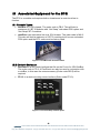
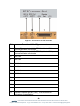
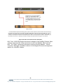
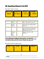
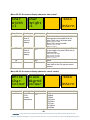
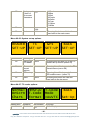
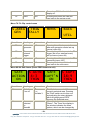
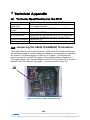
eyeheight BT-2 SDI LTC/VITC time code reader user manual Table of Contents 1 System Overview ...............................................................................................4 1.1 Drop-Frame indicator ..............................................................................5 1.2 Applications for the BT-2.........................................................................5 1.3 Associated Equipment for the BT-2 ........................................................6 1.3.1 Chassis Types .....................................................................................6 1.3.2 Control Surfaces ..................................................................................6 2 Installation ..........................................................................................................8 2.1 Installation of the BT-2 product ...............................................................8 2.2 Installing the BT-2 into a flexiBox............................................................8 2.3 Connecting Video to an BT-2 ..................................................................8 2.4 Connecting Panels to the BT-2 .............................................................10 3 Operation .........................................................................................................12 3.1 Manual control of the BT-2....................................................................12 3.2 Automation Control of the BT-2.............................................................12 3.3 Operational Menus for the BT-2............................................................13 4 Technical Appendix ..........................................................................................28 4.1 Technical Specification for the BT-2 .....................................................28 4.2 Jumpering the I-BUS (CAN-BUS) Termination .....................................28 -2eyeheight Unit 34 Park House Watford Business Park Greenhill Crescent Watford Herts GB WD18 8PH Reg. No. 2855535 Telephone: +44 (0) 1923 256 000 Fax: +44 (0) 1923 256 100 email: [email protected] Table of Figures Figure 1-1 The BT-2 colour correction PCB. .........................................................4 Figure 1-2 Block diagram of the BT-2 timecode reader.........................................5 Figure 1-3 flexiBox with flexiPanel fitted................................................................6 Figure 1-4 FP-10 desktop modular panel ..............................................................6 Figure 1-5 FP-9 1RU modular panel .....................................................................7 Figure 2-1 Connections for a BT-2 module. .........................................................9 Figure 2-2 I-Bus Connections and Termination...................................................11 Figure 4-1 Location Of I-Bus Termination Link....................................................28 -3eyeheight Unit 34 Park House Watford Business Park Greenhill Crescent Watford Herts GB WD18 8PH Reg. No. 2855535 Telephone: +44 (0) 1923 256 000 Fax: +44 (0) 1923 256 100 email: [email protected] 1 System Overview The BT-2 Burnt-in Timecode unit extracts the Vertical Interval Timecode (VITC) or the Longitudinal Timecode (LTC) and displays this as ASCII Characters on the screen. The main features of the BT-2 are as follows: Reads Longitudinal and Vertical interval Timecode (from an SDI Input). Displays timecode on-screen with a viewing option on the Flexipanel LCD displays. LTC, VITC, Auto LTC and Auto VITC modes of operation. Displays HH:MM:SS:FF and user bits with field mark. Re-Inserts VITC driven by the LTC input. (LTC to VITC conversion) 4 different display modes with user selectable screen position/size and user selectable character colour and background colour. Integral "Safe area generator" with cursors for 4:3 14:9 and 16:9 formats. Remote Character display on/off using GPI. Timecode Trigger feature enables timed remote control of a user device. Reads 25/30 frame timecode with drop frame indication for 525 operation 8 User Memories Figure 1-1 The BT-2 colour correction PCB. -4eyeheight Unit 34 Park House Watford Business Park Greenhill Crescent Watford Herts GB WD18 8PH Reg. No. 2855535 Telephone: +44 (0) 1923 256 000 Fax: +44 (0) 1923 256 100 email: [email protected] Box Gen. #1 (Safe areas) SDI Input VITC READER 24 CHR ON-SCREEN DISPLAY & VITC INSERT SDI Output#1 Box Gen. #2 (Safe areas) LTC Input GPI INPUT LTC READER AND GPI INTERFACE. REMOTE START Figure 1-2 Block diagram of the BT-2 timecode reader This unit consists of 2 generic Box generators, which perform the onscreen Safe Area and safe caption generation. This leads into a VITC Reader with programmable line selection. The VITC reader does full hardware CRCC checking for validity. If EITHER of the selected lines is valid the unit will assume that the VITC is valid. Alternatively the LTC can be read. The LTC reader is software based using a microcontroller and will read up to at least +/-8x normal speed and down to 1/5 speed. The Timecode information from the VITC or the LTC can be displayed on the 24 chr on-screen display. The LTC is deemed to be invalid when the LTC reader cannot find a valid LTC header (24 short consecutive transitions). The GPI input is used to remotely control the on-screen display. The remote start output can go on/off at programmable timecode points. 1.1 Drop-Frame indicator The Output on-screen timecode reader will indicate drop-frame timecode (This is only applicable for 30 frame timecode) The flag is indicated by a “dot” between the frames and the seconds instead of a “colon” 1.2 Applications for the BT-2 Applications for the BT-2 include the following: Offline editing in-vision time code stamping. General time code reading. Timecode activation of devices. -5eyeheight Unit 34 Park House Watford Business Park Greenhill Crescent Watford Herts GB WD18 8PH Reg. No. 2855535 Telephone: +44 (0) 1923 256 000 Fax: +44 (0) 1923 256 100 email: [email protected] 1.3 Associated Equipment for the BT-2 The BT-2 is a module and requires both a chassis and a control surface to function. 1.3.1 Chassis Types flexiBox is a 1RU chassis. The order code is FB-9. This will hold a maximum of 6 BT-2 Modules with “Hot Swap” redundant PSU option and “Hot Swap” BT-2 modules. maxiBox is an alternative low cost 1RU chassis. The order code is MX-9. This also will hold a maximum of 6 BT-2 modules but it has no redundant PSU option and the BT-2 units must be factory fitted. Figure 1-3 flexiBox with flexiPanel fitted 1.3.2 Control Surfaces flexiPanel is a IRU control surface that fits on the Front of a 1RU flexiBox. The order code is FP-9. A FlexiPanel can also be used in conjunction with a miniBox, in this case the extra accessory (Order code RR-9) will be required FP-10 is a desk mounting control surface (Order code FP-10). Figure 1-4 FP-10 desktop modular panel -6eyeheight Unit 34 Park House Watford Business Park Greenhill Crescent Watford Herts GB WD18 8PH Reg. No. 2855535 Telephone: +44 (0) 1923 256 000 Fax: +44 (0) 1923 256 100 email: [email protected] Figure 1-5 FP-9 1RU modular panel -7eyeheight Unit 34 Park House Watford Business Park Greenhill Crescent Watford Herts GB WD18 8PH Reg. No. 2855535 Telephone: +44 (0) 1923 256 000 Fax: +44 (0) 1923 256 100 email: [email protected] 2 Installation 2.1 Installation of the BT-2 product If this unit is already pre-installed in a flexiBox (FB-9), or a maxiBox, with either a local or a remote panel from the factory then refer to the "Hardware Installation Guide" which will be enclosed with the system. If this unit is pre-installed in a miniBox (MB-9), then also refer to the "Hardware Installation Guide" which will be enclosed with the system If this unit has been ordered separately, we assume here that you already have a flexiBox system with a Flexipanel and that the flexiBox has at least one spare slot for the BT-2 card. 2.2 Installing the BT-2 into a flexiBox To install the BT-2 into a flexiBox it is desirable (but not necessary) to power down the flexiBox. Follow these instructions. On the rear of the flexiBox are 6 slots for Products. Remove any spare blanking plate. There are 2 off M2.5 Screws, which require unfastening for each blanking plate. Slide the Product PCB into the spare slot and firmly push it "home". Use the two thumbscrews to fasten the unit in place. Now refer to the "GeNETics User Guide". If your system consists of a single flexiBox with a single flexiPanel then refer to the section titled "flexiPanel Auto Set-up". If your system is part of a network with more than one flexiPanel then refer to the section titled "flexiPanel Manual Set-up". This will guide you through acquiring your product as a device on the flexiPanel. 2.3 Connecting Video to an BT-2 The BT-2 connections are shown below. -8eyeheight Unit 34 Park House Watford Business Park Greenhill Crescent Watford Herts GB WD18 8PH Reg. No. 2855535 Telephone: +44 (0) 1923 256 000 Fax: +44 (0) 1923 256 100 email: [email protected] Figure 2-1 Connections for a BT-2 module. Function of 25w D-Type connector. Pin# 1. 3. General Purpose Output #1a (GPO1a). Isolated Relay closure. Activates remote start General Purpose Output #1b (GPO1b). Isolated Relay closure. Activates remote start Not Used 4. Not Used 5. Not Used 6. Not Used 7. Not Used 8. Not Used 2. 9. 10. 11. 12. 13. General Purpose Input #1 (GPI1). Pull to Ground to activate on screen display. -9- eyeheight Unit 34 Park House Watford Business Park Greenhill Crescent Watford Herts GB WD18 8PH Reg. No. 2855535 Telephone: +44 (0) 1923 256 000 Fax: +44 (0) 1923 256 100 email: [email protected] 14. Not Used 15. Not Used 16. Not Used 17. Not Used 18. Not Used 19. Not Used 20. Not Used 21. Time Code Input (LTC) Balanced (+) 22. Time Code Input (LTC) Balanced (-) 23. Not Used 24. Not Used 25. GND 2.4 Connecting Panels to the BT-2 The BT-2 may be operated using a FP-9 Flexipanel locally mounted. For a more operational environment the BT-2 may be supplied with a desk mounting FP-10 unit. For detailed information on connecting remote panels refer to the section “Connection of Remote Panels to a flexiBox” in the geNETics Hardware Installation Guide. Below is shown a typical system consisting of an BT-2 in a flexiBox controlled by a remote FP-9. - 10 eyeheight Unit 34 Park House Watford Business Park Greenhill Crescent Watford Herts GB WD18 8PH Reg. No. 2855535 Telephone: +44 (0) 1923 256 000 Fax: +44 (0) 1923 256 100 email: [email protected] ** Connect Pins 1,2,4,7,9 from chassis to panels (1:1). Use twisted pair AES Digital Audio cable for pins 2 and 7. Pins 1,4,9 carry power 0.5 Amp, 13V. Use cable with a least a 1 amp rating for pins 1,4,9. Cable llength should not exceed 250m. ** I-Bus pins 2 & 7 ** The I-BUS Network requires terminating with 100 Ohms at each extreme end of the network. Ensure that this is done either by an external 100 ohm resistor OR ONE Panel/Product at each end has the termination set. See the "Genetics User Guide" Under the sections "Flexipanel Power/I-BUS Jumpers".For the 4RU Panels see “4RU Panel (FP-10) Jumpers for I-BUS” and “4RU Panel (VP-10, SW-10, AP-10) Jumpers for I-BUS” . Alternatively The termination can be set on a Product (ie the MW-2 module). Information about this is given in this manual. Figure 2-2 I-Bus Connections and Termination N.B. From 1/10/02 Eyeheight introduced a change in the flexiBox Chassis. Most versions now have two 9 way connectors on the rear labelled “I-Bus” and “DBus”. The “I-Bus” connector is the same as the previously labelled “Can-B” connector. Although a maxiBox is shown in this diagram the same arrangement applies for a flexiBox chassis. - 11 eyeheight Unit 34 Park House Watford Business Park Greenhill Crescent Watford Herts GB WD18 8PH Reg. No. 2855535 Telephone: +44 (0) 1923 256 000 Fax: +44 (0) 1923 256 100 email: [email protected] 3 Operation 3.1 Manual control of the BT-2 Manual Control of the BT-2 is done using one or more of the following control surfaces: The 1RU FP-9 Flexipanel. The FP10 Desk mounting Panel The FP-9 and the FP-10 have identical manual control systems. (The FP-10 is simply a desktop version of the FP-9). The BT-2 is, as are all genetics modules, controlled using a set of MENUS. Each of these menus contains up to 3 parameters that are adjusted using the rotary digipots. The Menus define all of the adjustable operational parameters in the BT-2. Pressing the rotary digipots brings the parameter to its default value, if it has one. Device selection is done using the device select switches which, when pressed, will offer the name of the device in the LCD Window. Modules can be acquired and then de-acquired using the set-up switch. For a full description of the operation philosophy of the geNETics system refer to the “geNETics User Guide” (section “Operation of the flexiPanel”) A full list of the Menus and their functions are given in section 3 of this chapter. 3.2 Automation Control of the BT-2 Automation of the geNETics products is achieved via an RS422 port.** This port is marked RS422 on the rear of a flexiBox. For the port to work a flexiPanel MUST be connected locally on the front of the flexiBox. Automation control of the BT-2 can be done using two protocol methods: geNETics Automation Protocol. PresTX Automation Protocol. Genetics protocol is described in detail in the “GeNETics User Guide” section titled “Automation Protocol on the geNETics Platform”. The menu list in section 3 of this chapter contains the data information for the protocol. PresTX Automation Protocol is used only for the PresTX Presentation Mixer and channel branding system. In this case an AU-2 Automation card is also required. Refer to the PresTX Product manual **On most flexiBoxes later than 1/10/02 the RS422 port has been replaced by a “D-Bus” Port. The D-Bus port is for High Speed data transfer and is not used for serial control. In order to achieve serial control of any products on an I-Bus network Eyeheight Ltd have developed a RS232I-bus converter “dongle”, (DG9) which enables greater flexibility of products on the I-Bus network whilst using the same protocols as the RS422 port. Please refer to the “User guide for the DG-9 eyeheight dongle and set-up software. - 12 eyeheight Unit 34 Park House Watford Business Park Greenhill Crescent Watford Herts GB WD18 8PH Reg. No. 2855535 Telephone: +44 (0) 1923 256 000 Fax: +44 (0) 1923 256 100 email: [email protected] 3.3 Operational Menus for the BT-2 Menu 00-03: Top level controls SET-UP OnScrn UTIL VIEW MODE Format (-625) T.CODE Menu Num. 0 Heading Set-Up System On Screen Display Format Automation N/A 2 Utilities N/A 3 View the Timecode on the LCD display N/A 1 N/A Function Pressing this will take you to further set-up mode options (menu 60). Pressing this button will take you to further on-screen display options (menu 44). Pressing this button will take you to system “extras” such as the safe area generator and the timecode trigger facility. (menu 76) Pressing this button will cause the display to show the current timecode. NOTE: MENUS FROM 0543 ARE NOW “HIDDEN”. THIS HAS BEEN DONE FOR AUTOMATION TO REMAIN COMATIBLE WITH VERSIONS OF SOFTWARE FROM 2.5 AND BELOW. THE MENUS WILL STILL EXIST FOR AUTOMATION PURPOSES BUT ARE NO LONGER DOCUMENTED. Menu 44-47: On-Screen display control POSI’N SIZE COLOUR BACK - 13 eyeheight Unit 34 Park House Watford Business Park Greenhill Crescent Watford Herts GB WD18 8PH Reg. No. 2855535 Telephone: +44 (0) 1923 256 000 Fax: +44 (0) 1923 256 100 email: [email protected] Menu Num. 44 Heading On Screen display position Automation N/A Function Pressing this button will Take you to the on-screen display positioning menus (menu 48) 45 On Screen display size N/A Pressing this button will Take you to the on-screen display character size menus (menu 52) 46 On Screen display colour N/A Pressing this button will Take you to the on-screen display character colour menus. (menu 56). 47 BACK N/A Pressing this button will take the user back to the main (top) menu. Menu 48-51: On-screen display position control Horizl Vertcl Positn Positn =268 =240 Menu Num. 48 49 50 51 Heading Horizontal Position of burnt-in display. Vertical Position of burnt-in display. Back BACK OnScrn Automation 0719 28272[*] 28232 in 525 N/A N/A Function In Horizontal Luma Pixels 0=Start at LHS 719=Line at RHS In vertical lines 28=Start at Line Top 232/272=Line at Bottom none Pressing this button will take the user back to the On screen menu options. - 14 eyeheight Unit 34 Park House Watford Business Park Greenhill Crescent Watford Herts GB WD18 8PH Reg. No. 2855535 Telephone: +44 (0) 1923 256 000 Fax: +44 (0) 1923 256 100 email: [email protected] Menu 52-55: On-screen display character size control Char Width =1 Menu Num. 52 Char Height =1 Heading Horizontal Size of burnt-in display. BACK OnScrn Automation 031 Function Each unit adds an extra pair of luma pixels to the width of a chr pixel. Each chr is 8 pixels wide. Size0=16 luma chr width Size1=32 luma chr width Size2=48 luma chr width And so on up to 31. 53 54 55 Vertical Size of burnt-in display Back Each unit adds an extra pair of lines to the height of a pixel. Each chr is 8 pixels high. 031 Size0=16 line chr height Size1=32 line chr height Size2=48 line chr height And so on up to 31. N/A N/A None Pressing this button will take the user back to the On screen menu options. Menu 56-59: On-screen display character colour control White Black Char Bkgrnd Colour Colour Menu Num. 56 Heading Text Colour of On screen characters BACK OnScrn Automation 07 Function 0=Black 1=Blue 2=Red 3=Purple 4=Green 5=Cyan 6=Yellow 7=White - 15 eyeheight Unit 34 Park House Watford Business Park Greenhill Crescent Watford Herts GB WD18 8PH Reg. No. 2855535 Telephone: +44 (0) 1923 256 000 Fax: +44 (0) 1923 256 100 email: [email protected] 57 Background Colour of On screen characters 58 None 59 Back 0=Black 1=Blue 2=Red 3=Purple 4=Green 5=Cyan 6=Yellow 7=White 07 N/A N/A Pressing this button will take the user back to the main menu Menu 60-63: System set-up options READER TC GPI BACK SET-UP SET-UP SET-UP SET-UP Menu Num. 60 Heading Set-up the TC reader Automation None Function Pressing this will take you to the TC reader set-up menus (menu 64) 61 None Pressing this will take you to the TC format menus (menu 68) 62 Timecode format options GPI set-up None 63 Back None Pressing this will take you to the GPI enable menu. (menu 72) Pressing this button will take the user back to the top menu Menu 64-67: TC reader options. Normal HMSF+U T.Code BACK OnScrn T.Code Mode Chars Format =AuVTC Set-Up Menu Num. 64 Heading Enable the Automation 02 Function 0=No Display - 16 eyeheight Unit 34 Park House Watford Business Park Greenhill Crescent Watford Herts GB WD18 8PH Reg. No. 2855535 Telephone: +44 (0) 1923 256 000 Fax: +44 (0) 1923 256 100 email: [email protected] 65 burnt-in display Display mode of burnt-in Timecode display 66 Timecode Reading Mode 67 Back 1=Chrs Displayed 2=Chrs+Box Display 0=HH:MM:SS 1=HH:MM:SS:FF* 2=HH:MM:SS:FF* UU-UU-UU-UU Notes: *=Field Mark UU=User Bits 0=VITC, Read from VITC Only. 1=LTC, Read from LTC Only. 2=Auto VITC, Read from VITC unless the VITC is not valid, then read from LTC. 3=Auto LTC, Read from LTC unless the LTC is not valid, then read from VITC. 02 03 N/A Pressing this button will take the user back to the set-up mode options. Menu 68-71: Timecode set-up options. VITC L1=19 L2=21 Menu Num. 68 LTC VITC BACK Offset Insert Is OFF =AUTO Set-up Heading Select VITC Line numbers Automation Function When this button is pressed to "Green". The Three-line display in the window indicates the two options, which can be changed by adjusting the two rotary digipots A and B. Digipot A Select VITC Line number 1 623 Digipot B Select VITC Line number 2 623 - 17 eyeheight Unit 34 Park House Watford Business Park Greenhill Crescent Watford Herts GB WD18 8PH Reg. No. 2855535 Telephone: +44 (0) 1923 256 000 Fax: +44 (0) 1923 256 100 email: [email protected] 69 LTC reader Offset This will offset the reader by the amount below. This is for LTC only 04 70 VITC Insert 0= +2 Fld 1= +1 Fld 2= IS OFF 3= -1 Fld 4= -2 Fld This allows new VITC to be inserted which are “driven” by the LTC input code. This effectively is an LTC to VITC converter. 02 0=off 1=on 2=Auto OFF = No new VITC is inserted ON = New VITC are permanently inserted AUTO = New VITC are inserted while valid LTC is present. If no valid LTC is present and Valid VITC is present, then the New inserted VITC are switched OFF allowing the good input VITC to pass. For this to occur the Reader MUST be set to AutoLTC (See menu 66) 71 Back N/A Pressing this button will take the user back to the set-up mode options. Menu 72-75: GPI enable Extern On GPI BACK Switch Screen Cntrol For Disply =ON Set-up Menu Num. 32 33 34 Heading Info Info GPI Enable Automation N/A N/A Function This enables the character onscreen display to be switched on and off remotely using GPI#1. A 0=off 1=on [01] - 18 eyeheight Unit 34 Park House Watford Business Park Greenhill Crescent Watford Herts GB WD18 8PH Reg. No. 2855535 Telephone: +44 (0) 1923 256 000 Fax: +44 (0) 1923 256 100 email: [email protected] 35 Back Ground on GPI#1 will switch the display off. Pressing this button will take the user back to the set-up mode. N/A Menu 76-79: Clip control menu MEMS S.AREA TRIG GEN TALLY BACK UTIL Menu Num. 76 Heading Safe area generator Automation N/A Function Pressing this will take you to the safe area generator control set-up menus (menu 80) 77 Time code N/A Pressing this will take you to the TC external trigger (set off an external event) trigger. set-up menus (menu 84) 78 Memories N/A Pressing this will take you to the TC memories (menu 100) 79 Back N/A Pressing this button will take the user back to the utils menu. Menu 80-84: Safe Areas (Press PREV button to exit) SAFE S ACTN SAFE S CAPT ACTION 4:3 CAPT’N 16:9 ON THIN ON THIN Menu Num. 80 Heading Safe Area 1 on-off Automation On Off [01] Variable 3 81 Area selected by menu#4 Function This Switches on and off the currently selected area. Pressing the "Red" switch next to this one and adjusting the rotary digipots with the lighted green LED's chooses the Selected area. When this button is pressed to "Green". The Three-line display in the window indicates the three options, which can be changed by - 19 eyeheight Unit 34 Park House Watford Business Park Greenhill Crescent Watford Herts GB WD18 8PH Reg. No. 2855535 Telephone: +44 (0) 1923 256 000 Fax: +44 (0) 1923 256 100 email: [email protected] adjusting the three rotary digipots A, B and C. Digipot A S.Action S.Capt. Dig Edge An Edge [03 (Variable 1) Digipot B 4:3 16:9 16p4:3 16p149 43p16:9 [04] (Variable 2) ”A” Determines the basic Function Selects "Safe Action" option Selects "Safe Caption" option Selects "Digital Edge" option Selects the "An. Edge" option ”B” Determines the Screen Format Standard 4:3 Screen Standard 16:9 Screen 16:9 Shoot to protect 4:3 16:9 Shoot to protect 14:9 (*) 4:3 Shoot to protect 16:9 (*) (*) -- Not available in 525 Digipot C Thin Thick Shade Black [03] (Variable 3) 82 Safe Area 2 on-off On Off [01] (Variable 3) 83 Area selected by menu#6 Digipot A S.Action S.Capt. Dig Edge An Edge [03] (Variable 1) ”C” Determines the Style of Indicate Thin White lines are used Thick White lines are used Shade is used for "danger area" Black is used for "danger area" This Switches on and off the currently selected area. Pressing the "Red" switch next to this one and adjusting the rotary digipots with the lighted green LED's chooses the Selected area. When this button is pressed to "Green". The Three-line display in the window indicates the three options, which can be changed by adjusting the three rotary digipots A, B and C. “A” determines the basic Function Selects "Safe Action" option Selects "Safe Caption" option Selects "Digital Edge" option Selects the "An. Edge" option - 20 eyeheight Unit 34 Park House Watford Business Park Greenhill Crescent Watford Herts GB WD18 8PH Reg. No. 2855535 Telephone: +44 (0) 1923 256 000 Fax: +44 (0) 1923 256 100 email: [email protected] Digipot B 4:3 16:9 16p4:3 16p149 43p16:9 [04] (Variable 2) “B” Determines the Screen Format. Standard 4:3 Screen Standard 16:9 Screen 16:9 Shoot to protect 4:3 16:9 Shoot to protect 14:9 (*) 4:3 Shoot to protect 16:9 (*) (*) -- Not available in 525 Digipot C Thin Thick Shade Black [03] (Variable 3) “C” Determines the Style of Indicate Thin White lines are used Thick White lines are used Shade is used for "danger area" Black is used for "danger area" Menu 84-87: Time code external trigger. (Press NEXT button for TRIG 2) T.Code Trig 1 Trig 1 Triggr Hrs=10 Hrs=10 =GO Min=34 Min=34 Menu Num. 84 Heading Time code trigger activation Automation 02 BACK util Function This will activate the Time code trigger. The trigger will activate at “Trig 1” timecode and de-activate at “Trig 2” timecode. 0=OFF, No trigger can occur. 1=GO, Triggers are enabled. 2=Done 1, Trigger 1 is assumed past and so Trig 2 will de-activate only. This may be read by automation to ensure trigger 1 has occurred. 85 When this button is pressed to "Green". The Three-line display in the window indicates the two Trigger 1 (Activate) Hours and - 21 - eyeheight Unit 34 Park House Watford Business Park Greenhill Crescent Watford Herts GB WD18 8PH Reg. No. 2855535 Telephone: +44 (0) 1923 256 000 Fax: +44 (0) 1923 256 100 email: [email protected] minutes. options, which can be changed by adjusting the two rotary digipots A and B. “A” determines the Hours at which the trigger will activate. Level “A” 023 “B” determines the Minutes at which the trigger will activate. Level “B” 059 86 Trigger 1 (Activate) Seconds and frames. When this button is pressed to "Green". The Three-line display in the window indicates the two options, which can be changed by adjusting the two rotary digipots A and B. “A” determines the Seconds at which the trigger will activate. Level “A” 059 Level “B” 024 (or 29 for 525). 87 Back N/A “B” determines the Frames at which the trigger will activate. Pressing this button will take the user back to the utils menu. Menu 88-91: Time code external trigger. (Press PREV button for TRIG 1) Trig 2 Trig 2 Hrs=10 Hrs=10 Min=34 Min=34 Menu Num. 88 89 Heading none Automation N/A Trigger 2 (Deactivate) Hours and minutes. BACK util Function When this button is pressed to "Green". The Three-line display in the window indicates the two options, which can be changed by adjusting the two rotary digipots A and B. “A” determines the Hours at which the trigger will de-activate. Level “A” 023 - 22 - eyeheight Unit 34 Park House Watford Business Park Greenhill Crescent Watford Herts GB WD18 8PH Reg. No. 2855535 Telephone: +44 (0) 1923 256 000 Fax: +44 (0) 1923 256 100 email: [email protected] Level “B” “B” determines the Minutes at which the trigger will de-activate. 059 90 Trigger 1 (Deactivate) Seconds and frames. When this button is pressed to "Green". The Three-line display in the window indicates the two options, which can be changed by adjusting the two rotary digipots A and B. “A” determines the Seconds at which the trigger will de-activate. Level “A” 059 Level “B” 024 (or 29 for 525). 91 Back N/A “B” determines the Frames at which the trigger will de-activate. Pressing this button will take the user back to the utils menu. Menu 92-95: Time code view. 15 Hrs 12 Min 15 Sec VITC CODE DISPLY BACK Menu Num. 92 Heading Current TC hours and VITC/LTC indication Automation 023 read only Function This is the current Hours display of the input timecode. 93 Current TC hours and VITC/LTC indication 059 read only This is the current Minutes display of the input timecode. 94 Current TC hours and VITC/LTC indication 059 read only This is the current Seconds display of the input timecode. - 23 eyeheight Unit 34 Park House Watford Business Park Greenhill Crescent Watford Herts GB WD18 8PH Reg. No. 2855535 Telephone: +44 (0) 1923 256 000 Fax: +44 (0) 1923 256 100 email: [email protected] 95 Back N/A Pressing this button will take the user back to the top menu. Automation Function Not used Menu 96-99: NOT USED. Menu Num. 96 Heading 97 Not used 98 Not used 99 Not used Menus 100-103 Memory 13 menus (NEXT to navigate) MEM1 ----------Menu Num. 100 MEM2 ----------- Heading MEM1 Automation 1=Recall 101 MEM2 1=Recall 102 MEM3 1=Recall 103 BACK none MEM3 ----------- BACK Function Pressing this will recall Memory number 1.User Names can be programmed in to the memories using a keyboard. See “geNETics User guide”, section “Giving product Memories names” Pressing this will recall Memory number 2. Pressing this will recall Memory number 3. Go To the Util Menus - 24 eyeheight Unit 34 Park House Watford Business Park Greenhill Crescent Watford Herts GB WD18 8PH Reg. No. 2855535 Telephone: +44 (0) 1923 256 000 Fax: +44 (0) 1923 256 100 email: [email protected] Menus 104-107 Memory 46 menus (NEXT/PREV to navigate) MEM4 ----------Menu Num. 104 MEM5 ----------- Heading MEM4 Automation 1=Recall 105 MEM5 1=Recall 106 MEM6 1=Recall 107 BACK none MEM6 ----------- BACK Function Pressing this will recall Memory number 4. Pressing this will recall Memory number 5. Pressing this will recall Memory number 6. Go To the Util Menus Menus 108-111 Save memory 13 menus (NEXT/PREV to navigate) SAVE MEM1 -----Menu Num. 108 109 110 111 SAVE MEM2 ------ Heading SAVE MEM1 SAVE MEM2 SAVE MEM3 BACK Automation 1=Save 1= Save 1= Save none SAVE MEM3 ------ BACK Function Pressing this will Save Memory number 1. Pressing this will Save Memory number 2. Pressing this will Save Memory number 3. Go To the Util Menus Menus 112-115 Save memory 46 menus (NEXT/PREV to navigate) SAVE MEM4 SAVE MEM5 SAVE MEM6 BACK - 25 eyeheight Unit 34 Park House Watford Business Park Greenhill Crescent Watford Herts GB WD18 8PH Reg. No. 2855535 Telephone: +44 (0) 1923 256 000 Fax: +44 (0) 1923 256 100 email: [email protected] Menu Num. 112 113 114 115 Heading SAVE MEM4 SAVE MEM5 SAVE MEM6 BACK Automation 1= Save 1= Save 1= Save none Function Pressing this will Save Memory number 4. Pressing this will Save Memory number 5. Pressing this will Save Memory number 6. Go To the Util Menus Menus 116-119 Software version menu (PREV to navigate) SOFTWA RE Ver ------ ---- Menu Num. 116 117 118 119 Heading Info Info none BACK Automation none none none none BT-2 250702 Ver2.6 BACK Function Information Information Software Version Information Go To the Util Menus Menus 120-123 Power on memory menus. (PREV to navigate) Set As Pow On Memory Menu Num. 120 121 122 123 Recall Pow On Memory Heading Set As Pow On Memory Recall Pow On Memory Total Reset Automation 1=Set BACK none 1=Recall 1=Reset Total! Reset! !!!!!! BACK Function Pressing this will set the current system set-up as the Power on memory default. Pressing this will recall The Power-on memory set up in the last menu. Pressing this will cause a first Birthday of the unit. All current memories and settings will be lost. Go To the Util Menus - 26 eyeheight Unit 34 Park House Watford Business Park Greenhill Crescent Watford Herts GB WD18 8PH Reg. No. 2855535 Telephone: +44 (0) 1923 256 000 Fax: +44 (0) 1923 256 100 email: [email protected] - 27 eyeheight Unit 34 Park House Watford Business Park Greenhill Crescent Watford Herts GB WD18 8PH Reg. No. 2855535 Telephone: +44 (0) 1923 256 000 Fax: +44 (0) 1923 256 100 email: [email protected] 4 Technical Appendix 4.1 Technical Specification for the BT-2 SDI Input Longitudinal Time Code Input SDI Input Line Length Number of Outputs SDI Output Jitter 1 270Mbit Serial Digital Video Inputs 75 Ohm Differential 600ohm +6dB-12dB. Reads from +0.2 +8 speed timecode. At least 200 Meters of PSF1/3 (Typically 275 Meters) 1 Output SDI 270 MHz. The system will add less than 0.2UI to the input Jitter. (This is only guaranteed on issue 2 or later cards) Current Consumption <800mA at +5V Size 215mm by 100mm 4.2 Jumpering the I-BUS (CAN-BUS) Termination The I-BUS Network is the "control system" under which all Products and Panels are networked together. Under certain circumstances it is necessary to terminate the network. This can be done on a Panel or a "Product". To terminate this product, locate J6 on the BT-2 Processor Card supplied which is between U1 (The large square "chip") and the Edge connector. (This is on the half of the card labelled "CHP-100 Spartan2 Processor"). Jumper this with a 2mm link. J6 Figure 4-1 Location Of I-Bus Termination Link - 28 eyeheight Unit 34 Park House Watford Business Park Greenhill Crescent Watford Herts GB WD18 8PH Reg. No. 2855535 Telephone: +44 (0) 1923 256 000 Fax: +44 (0) 1923 256 100 email: [email protected]